WO2012169428A1 - 無線中継装置、無線送信装置、無線受信装置、無線通信システム、制御プログラムおよび集積回路 - Google Patents
無線中継装置、無線送信装置、無線受信装置、無線通信システム、制御プログラムおよび集積回路 Download PDFInfo
- Publication number
- WO2012169428A1 WO2012169428A1 PCT/JP2012/064141 JP2012064141W WO2012169428A1 WO 2012169428 A1 WO2012169428 A1 WO 2012169428A1 JP 2012064141 W JP2012064141 W JP 2012064141W WO 2012169428 A1 WO2012169428 A1 WO 2012169428A1
- Authority
- WO
- WIPO (PCT)
- Prior art keywords
- relay
- csi
- wireless
- precoding
- transmission
- Prior art date
- Legal status (The legal status is an assumption and is not a legal conclusion. Google has not performed a legal analysis and makes no representation as to the accuracy of the status listed.)
- Ceased
Links
Images





Classifications
-
- H—ELECTRICITY
- H04—ELECTRIC COMMUNICATION TECHNIQUE
- H04B—TRANSMISSION
- H04B7/00—Radio transmission systems, i.e. using radiation field
- H04B7/02—Diversity systems; Multi-antenna system, i.e. transmission or reception using multiple antennas
- H04B7/04—Diversity systems; Multi-antenna system, i.e. transmission or reception using multiple antennas using two or more spaced independent antennas
- H04B7/0413—MIMO systems
- H04B7/0417—Feedback systems
-
- H—ELECTRICITY
- H04—ELECTRIC COMMUNICATION TECHNIQUE
- H04B—TRANSMISSION
- H04B7/00—Radio transmission systems, i.e. using radiation field
- H04B7/02—Diversity systems; Multi-antenna system, i.e. transmission or reception using multiple antennas
- H04B7/04—Diversity systems; Multi-antenna system, i.e. transmission or reception using multiple antennas using two or more spaced independent antennas
- H04B7/06—Diversity systems; Multi-antenna system, i.e. transmission or reception using multiple antennas using two or more spaced independent antennas at the transmitting station
- H04B7/0613—Diversity systems; Multi-antenna system, i.e. transmission or reception using multiple antennas using two or more spaced independent antennas at the transmitting station using simultaneous transmission
- H04B7/0615—Diversity systems; Multi-antenna system, i.e. transmission or reception using multiple antennas using two or more spaced independent antennas at the transmitting station using simultaneous transmission of weighted versions of same signal
- H04B7/0619—Diversity systems; Multi-antenna system, i.e. transmission or reception using multiple antennas using two or more spaced independent antennas at the transmitting station using simultaneous transmission of weighted versions of same signal using feedback from receiving side
- H04B7/0621—Feedback content
- H04B7/0626—Channel coefficients, e.g. channel state information [CSI]
-
- H—ELECTRICITY
- H04—ELECTRIC COMMUNICATION TECHNIQUE
- H04B—TRANSMISSION
- H04B7/00—Radio transmission systems, i.e. using radiation field
- H04B7/14—Relay systems
- H04B7/15—Active relay systems
- H04B7/155—Ground-based stations
Definitions
- the present invention relates to a radio relay device, a radio transmission device, a radio reception device, a radio communication system, a control program, and an integrated circuit that transmit and receive signals while suppressing interference in advance by signal processing.
- MIMO Multiple-Input Multiple-Output
- Single-user MIMO Single User MIMO
- Single User MIMO Single User MIMO
- a system has been proposed in which the number of transmission antennas included in a base station device (wireless transmission device) is significantly larger than the number of reception antennas included in a terminal station device (wireless reception device).
- a multi-user MIMO Multi-User MIMO
- MIMO multiplexes data sequences addressed to a plurality of terminal station devices (users) in order to further improve the system throughput by effectively using the transmission antenna of the base station device.
- Non-Patent Document 1 proposes several methods for generating a transmission signal for suppressing MUI at the time of reception in a terminal station apparatus.
- CSI Channel State Information
- the terminal does not apply a large load to the terminal station device.
- a transmission signal that can suppress MUI at the time of reception in the station apparatus can be generated.
- a weight matrix (linear filter) W H H (HH H + ⁇ I) ⁇ 1 (I is a unit matrix, ⁇ is a normalization coefficient) obtained by a minimum mean square error (MMSE) standard.
- linear precoding beamforming for precoding a transmission signal by linear processing, such as MMSE precoding for weighting the transmission signal.
- Nonlinear precoding Another example is nonlinear precoding.
- non-linear precoding an interference signal component obtained from CSI is subtracted from a transmission signal in advance, and a transmission signal is transmitted by non-linear processing that encodes the signal after interference subtraction to a signal point where transmission power is reduced in the signal space. Is precoded. As a result, transmission power that increases after interference subtraction can be suppressed.
- Tomlinson-Harashima precoding Tomlinson-Harashima precoding
- Non-Patent Document 2 Non-Patent Document 3, Non-Patent Document 4
- the terminal station apparatus on the receiving side also performs modulo operation similar to transmission on the received signal.
- modulo operation Mod tau modulo width tau, when a complex vector representing the received signal in the signal or receiver after interference subtraction on the transmission side [nu, represented by the formula (1).
- J is an imaginary unit
- floor (a) is the maximum integer not exceeding a
- Re ( ⁇ ) and Im ( ⁇ ) are the real part of the complex number ⁇ (corresponding to the in-phase component of the signal) and the imaginary part ( Corresponding to the orthogonal component of the signal).
- the non-linear processing here mainly means processing using processing in which discontinuities exist in output such as modulo arithmetic.
- a relay technique for relaying and transmitting a radio signal between a base station apparatus and a terminal station apparatus has been studied for the purpose of improving the throughput of users in the cell periphery.
- a relay technology for relaying radio signals an AF (Amplify and Forward) type relay technology that amplifies the received signal from the base station device and retransmits it to the terminal station device in the relay station device (wireless relay device), and relay DF (Decode and Forward) type relay technology that performs demodulation and error correction decoding on the received signal from the base station device once in the station device, performs error correction coding and modulation again, and retransmits to the terminal station device, etc.
- AF Anamplify and Forward
- relay DF Decode and Forward
- the AF type interference characteristics and noise from other cells received by the relay station apparatus are also amplified in power, so that transmission characteristics deteriorate.
- the amount of operation and the processing delay increase with the modulation / demodulation and error correction encoding / decoding processing in the relay station apparatus.
- Non-Patent Document 5 A method of performing user MIMO transmission has been proposed (Non-Patent Document 5).
- An object of the present invention is to provide a wireless relay device, a wireless transmission device, a wireless reception device, a wireless communication system, a control program, and an integrated circuit.
- the wireless relay device of the present invention is a wireless relay device that relays a plurality of data sequences by multiuser MIMO transmission, and shows a first propagation path state between the estimated own wireless relay device and a relay source.
- a first CSI generation unit that generates the CSI of the first wireless communication unit, a wireless transmission unit that transmits the first CSI to the relay source, and a propagation path between the estimated own wireless relay device and each of the plurality of relay destinations
- a second CSI acquisition unit for acquiring a second CSI indicating a state, and precoding based on the first CSI, and among data sequences transmitted from the relay source to a plurality of wireless relay devices at the same time,
- a precoding unit that performs precoding on the received data sequence based on the acquired second CSI after channel compensation. And transmitting simultaneously data sequence to the plurality of relay destinations.
- first CSI corresponds to “relay station CSI”
- second CSI corresponds to “terminal station CSI”.
- the “first CSI generation unit” corresponds to a “relay station CSI generation unit”.
- the “relay source” corresponds to a “wireless transmission device”
- the “relay destination” corresponds to a “wireless reception device”.
- at least one of “relay source” and “relay destination” corresponds to a “wireless relay device”.
- the wireless relay device of the present invention is characterized in that the precoding unit performs nonlinear precoding on a data sequence transmitted from the relay source.
- THP which is nonlinear precoding
- the wireless relay device of the present invention is characterized in that the precoding unit performs precoding on a data sequence transmitted from the relay source after making a temporary determination of received signal points. To do.
- error correction decoding is not performed on the received symbol addressed to each radio reception apparatus that is the object of relay transmission, and a provisional determination of a received signal point with a smaller calculation amount is performed.
- precoding for multi-user MIMO can be performed on provisional determination, and the amount of computation and processing time of the wireless relay device can be reduced.
- the wireless transmission device of the present invention is a wireless transmission device that transmits a plurality of data sequences by multi-user MIMO transmission, and is between the estimated own wireless transmission device and each of the plurality of wireless relay devices.
- a relay station CSI acquisition unit that acquires a relay station CSI indicating a propagation path state of the relay station, and a precoding unit that performs precoding on a plurality of data sequences based on the acquired relay station CSI, The data sequence on which precoding is performed is transmitted to the plurality of radio relay apparatuses simultaneously.
- each radio relay apparatus receives the precoding symbol
- interference due to a signal to other than the own radio relay apparatus is canceled, and only the signal to be relayed by the own radio relay apparatus is received.
- the transmission data modulation symbols addressed to each wireless reception device to be relayed and transmitted by each wireless relay device are also received separately without interference.
- signal separation processing in the wireless relay device is not necessary, and the amount of computation of the wireless relay device can be reduced and the processing delay can be shortened.
- each wireless reception device that is a final reception subject of transmission data exists more than the wireless relay device.
- the wireless transmission device it is not necessary to know the propagation path state between each wireless reception device, it is sufficient to know the propagation path state between each wireless relay device, and the CSI notified to the wireless transmission device The amount of information can be reduced.
- the radio relay apparatus since the radio relay apparatus is generally in a quasi-stationary state and the time variation of the propagation path is moderate, the notification frequency of the relay station CSI notified from each radio relay apparatus is set to the notification of the terminal station CSI. It can be greatly reduced compared to the frequency.
- the wireless transmission device of the present invention is characterized in that the precoding unit performs nonlinear precoding on the plurality of data series.
- THP which is nonlinear precoding
- the radio reception apparatus of the present invention is a radio reception apparatus that receives a data sequence subjected to multiuser MIMO transmission via the radio relay apparatus described in (1) above, and the second CSI A second CSI generation unit for generating the second CSI and a wireless transmission unit for transmitting the second CSI to the wireless relay device, wherein the wireless relay device performs precoding based on the second CSI. And receiving data sequences transmitted to a plurality of wireless reception devices at the same time.
- the wireless communication system of the present invention is a wireless communication system that performs multi-user MIMO transmission by relay, and the propagation path state between each of the estimated wireless transmitter and the plurality of wireless relay devices Based on a relay station CSI indicating a wireless transmission device that precodes a plurality of data sequences and simultaneously transmits the precoded data sequences to the plurality of wireless relay devices; A first CSI indicating a propagation path state between the wireless relay device and the relay source is generated and transmitted to the relay source, derived from the data sequence transmitted from the wireless transmission device, and the first CSI Precoding is performed on the basis of the received data sequence among the data sequences transmitted from the relay source to a plurality of wireless relay devices at the same time.
- Precoding is performed based on the second CSI indicating the propagation path state between the own radio relay apparatus and each of the plurality of relay destinations, and the received and precoded data sequence is A wireless relay device that simultaneously transmits to the plurality of relay destinations, the second CSI is generated and transmitted to the transmission source of the received data sequence, and is derived from the data sequence relayed by the wireless relay device, A radio receiving device that receives pre-coding at the transmission source of the received data sequence based on the second CSI and receives data sequences transmitted to a plurality of radio receiving devices at the same time. To do.
- the wireless communication system of the present invention is characterized in that multi-user MIMO transmission is performed from the wireless transmission device to the wireless reception device via a wireless relay device having a plurality of layers.
- a transmission signal from a wireless transmission device can be simultaneously transmitted to a plurality of wireless reception devices that are relayed and transmitted multiple times (multiple layers) by different wireless relay devices using spatial multiplexing in each layer.
- transmission efficiency can be improved.
- control program of the present invention is a control program for controlling the relay of a plurality of data sequences by multi-user MIMO transmission, and the propagation between the estimated wireless relay device to be controlled and the relay source
- a process of obtaining a second CSI indicating a propagation path state, precoding is performed based on the first CSI, and received from among the data series simultaneously transmitted from the relay source to a plurality of radio relay apparatuses.
- a process of performing precoding on the data sequence after propagation path compensation based on the acquired second CSI, and the data sequence on which the precoding has been performed are combined with the data sequence.
- a process of transmitting simultaneously to the relay destination a series of processes including, characterized in that to be executed by the wireless relay apparatus which is the control.
- the integrated circuit of the present invention is an integrated circuit that controls the relay of a plurality of data sequences by multiuser MIMO transmission, and is the propagation between the estimated wireless relay device to be controlled and the relay source.
- a function of generating a first CSI indicating a road state, a function of transmitting the first CSI to the relay source, and between the estimated wireless relay device to be controlled and each of a plurality of relay destinations A function of obtaining a second CSI indicating a propagation path state and precoding based on the first CSI, and received from among the data series transmitted from the relay source to a plurality of radio relay apparatuses at the same time.
- a function of performing precoding on the data sequence after propagation path compensation based on the acquired second CSI, and the data sequence on which the precoding has been performed are transmitted to the plurality of relay destinations.
- a function for simultaneously transmitting a series of functions including, characterized in that to exhibit to the wireless relay apparatus which is the control.
- the present invention when a transmission signal from a base station apparatus is relayed to a plurality of terminal station apparatuses via different relay station apparatuses, it becomes possible to transmit simultaneously using spatial multiplexing, and transmission efficiency Can be improved.
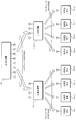
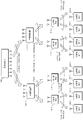
- FIG. 1 is a diagram illustrating a schematic configuration example of a wireless communication system according to each embodiment.
- base station apparatus 100 communicates with a plurality of terminal station apparatuses (for example, first to eighth terminal station apparatuses 120-1 to 120-8).
- terminal station apparatuses for example, first to eighth terminal station apparatuses 120-1 to 120-8.
- transmission data addressed to each terminal station device via a plurality of relay station devices (for example, the first relay station device 110-1 and the second relay station device 110-2).
- Multi-user MIMO transmission for spatially multiplexing and simultaneously communicating.
- transmission data addressed from the first terminal station device 120-1 to the fourth terminal station device 120-4 passes through the first relay station device 110-1 and passes through the fifth terminal station device 120-1.
- Transmission data addressed from ⁇ 5 to the eighth terminal station device 120-8 is transmitted via the second relay station device 110-2.
- base station apparatus 100 determines the state of the propagation path between each antenna of base station apparatus 100 and each antenna of each of relay station apparatuses 110-1 and 110-2 (the complex propagation path gain between each antenna, Based on propagation path state information (Channel State Information: CSI) indicating a desired precoding matrix index (Precoding / Matrix / Index: PMI) obtained from the propagation path state and the like.
- CSI Channel State Information
- PMI Precoding / Matrix / Index
- the first relay station device 110-1 includes the antennas of the first relay station device 110-1 and the first terminal station device 120-1 to the fourth terminal station device 120-4 as relay transmission destinations. Based on the CSI between each antenna, pre-coding is performed so that the transmission signals from the first relay station apparatus 110-1 to each terminal station apparatus do not become MUI, and multi-user MIMO transmission is performed.
- the second relay station device 110-2 includes the antennas of the second relay station device 110-2 and the fifth terminal station device 120-5 to the eighth terminal station device 120-8 as relay transmission destinations. Based on the CSI with each of the antennas, precoding is performed so that the transmission signals from the second relay station apparatus 110-2 to the terminal station apparatuses do not become MUIs, and multi-user MIMO transmission is performed.
- the base station apparatus selects N terminal station apparatuses from the first terminal station apparatus to the Nth terminal station apparatus from among the plurality of terminal station apparatuses, and K relay stations
- N terminal station apparatuses from the first terminal station apparatus to the Nth terminal station apparatus from among the plurality of terminal station apparatuses
- K relay stations A wireless communication system that transmits data via a device will be described as an example.
- N M ⁇ K.
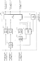
- FIG. 2 is a functional block diagram showing a configuration example of the base station apparatus 100 according to the first embodiment.
- Radio receiving section 210 receives a signal transmitted from each relay station apparatus using at least one of the N antennas of antenna sections 209-1 to 209-N.
- the relay station CSI acquisition unit 211 acquires the CSI transmitted by each relay station device from the received signal.
- this CSI is referred to as a relay station CSI
- the CSI transmitted by each terminal station device is referred to as a terminal station CSI.
- Encoding sections 201-1 to 201-N perform error correction encoding on transmission data sequences addressed to first to N-th terminal station devices, respectively. Further, when the coding rate of transmission data is selected, rate matching (puncture) is performed according to the coding rate.
- Modulators 202-1 to 202-N perform modulation on the transmission data sequences addressed to the first to Nth terminal station apparatuses, which have been error correction coded, respectively, and the first to Nth terminal station apparatuses, respectively. Output the modulation symbol for the destination. When a modulation method for transmission data addressed to each terminal station apparatus is selected, modulation is performed using the modulation method.
- DMRS multiplexing sections 203-1 to 203-N receive demodulation reference signals (Demodulation Reference Signal: DMRS), which are known symbols to be referred to in order to perform propagation channel compensation and demodulation of received signals in each relay station apparatus. Each is multiplexed on a modulation symbol addressed to the station apparatus.
- the multiplexed DMRS is precoded in the precoding unit 204 in the same manner as the modulation symbol. Further, multiplexing with DMRS may be performed by time division, for example, or may be performed by frequency division such as division by subcarriers.
- the precoding unit 204 receives each modulation symbol addressed to each of the first to N-th terminal station devices multiplexed with DMRS, and inputs based on the CSI of each relay station device acquired by the relay station CSI acquisition unit 211 Precoding is performed on each modulation symbol thus generated, and precoding symbols for each antenna of antenna units 209-1 to 209-N used for transmission are generated. Details of the precoding unit 204 will be described later.
- CRS multiplexing sections 205-1 to 205-N indicate the propagation path state between each antenna of antenna sections 209-1 to 209-N of base station apparatus 100 and each antenna of each relay station apparatus in each relay station apparatus.
- a common reference signal (Common Reference Signal: CRS), which is a known symbol to be referred to for estimation, is multiplexed on the precoding symbol of each antenna. Note that the multiplexed CRS is not precoded.
- the CRS multiplexing is preferably performed so that the CRS transmitted from each antenna of the base station apparatus 100 is received in a form that can be identified by each antenna of each relay station apparatus. Alternatively, it may be multiplexed by frequency division such as division by subcarriers.
- the IFFT units 206-1 to 206-N perform frequency time conversion such as Inverse ⁇ ⁇ ⁇ ⁇ Fast (Fourier Transform (IFFT) on the precoding symbols for each antenna on which CRS is multiplexed, Convert to signal.
- IFFT Inverse ⁇ ⁇ ⁇ ⁇ Fast
- IFFT Frier Transform
- GI insertion units 207-1 to 207-N insert a guard interval (GI) into the time domain signal for each antenna.
- Radio transmitting sections 208-1 to 208-N transmit signals with the GI inserted thereto through spatial multiplexing transmission through the antennas of antenna sections 209-1 to 209-N.
- the control unit 212 controls each of the above units and causes each process to be executed.
- FIG. 3 is a functional block diagram showing a configuration example of the precoding unit 204 according to the first embodiment.
- the precoding unit in this configuration example is represented as a precoding unit 204a.
- the complex channel gain between each antenna of the base station apparatus 100 and each antenna of each relay station apparatus is notified as CSI from the relay station, and Zero-Forcing precoding that is linear precoding is performed. A case where a precoding symbol is generated by coding will be described.
- the precoding unit 204 a includes a filter calculation unit 301 and a linear filter unit 302.
- the filter calculation unit 301 obtains, for each subcarrier, a channel matrix H that is acquired by the relay station CSI acquisition unit 211 and has a complex channel gain between each antenna of the base station apparatus 100 and each antenna of each relay station apparatus.
- channel matrix H and weight matrix W are N rows and N columns.
- the linear filter unit 302 multiplies the linear filter W calculated by the filter calculation unit 301 for each subcarrier, with the modulation symbols addressed to the first to N-th terminal station devices multiplexed with DMRS as inputs. Then, a precoding symbol to be transmitted is output from each antenna of each antenna unit 209-1 to 209-N. Assuming that s 1 to s N are modulation symbols addressed to the first to N-th terminal station devices multiplexed with DMRS and x 1 to x N are precoding symbols, this precoding is expressed by Equation (2).
- each relay station apparatus receives the precoding symbol, interference (MUI) due to a signal other than the own relay station apparatus is canceled by precoding, and only the signal to be relayed by the own relay station apparatus is received.
- interference due to a signal other than the own relay station apparatus
- transmission data modulation symbols destined for each terminal station apparatus to be relayed by each relay station apparatus are also individually separated without interference. Received in the state. This eliminates the need for signal separation processing in the relay station device, reduces the amount of computation of the relay station device, and shortens the processing delay.
- the base station apparatus it is not necessary to know the propagation path state between each terminal station apparatus (more than the relay station apparatus) that is the final receiver of the transmission data, and It is only necessary to know the state of the propagation path. Therefore, the information amount of CSI notified to the base station apparatus can be reduced. Further, in general, the relay station apparatus is often in a quasi-stationary state, and the time variation of the propagation path is moderate. Therefore, the notification frequency of the relay station CSI notified from each relay station apparatus is compared with the terminal station CSI. Can be greatly reduced.
- the precoding unit 204a calculates and uses an inverse matrix as a linear filter in the filter calculation unit 301.
- the MUI is not completely canceled at the time of reception, but the reception characteristics are improved because the received signal-to-interference plus noise power ratio (SINR) can be maximized.
- SINR received signal-to-interference plus noise power ratio
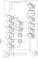
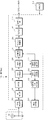
- FIG. 4 is a functional block diagram showing a configuration example of the relay station device 110a according to the first embodiment.
- This configuration example corresponds to the configuration example of relay station apparatuses 110-1 and 110-2 in the example of the wireless communication system of FIG.
- a case will be described as an example in which transmission data addressed to the first to M-th terminal station apparatuses is subjected to relay transmission.
- Radio receiving sections 402-1 to 402-M receive signals from the base station apparatus through M antennas 401-1 to 401-M.
- at least one of the wireless reception units 402-1 to 402-M is connected to each of the first to Mth terminals through at least one of the M antennas of the antenna units 401-1 to 401-M.
- a control signal including the terminal station CSI transmitted by each station apparatus is received.
- the terminal station CSI acquisition unit 419 acquires the terminal station CSI transmitted from each of the first to Mth terminal station apparatuses from the signals received from the first to Mth terminal station apparatuses.
- GI removal sections 403-1 to 403-M remove GI from the signals transmitted from the base station apparatuses received by the respective antennas.
- the FFT units 404-1 to 404 -M perform time-frequency conversion on the received signal from which the GI for each antenna is removed by fast Fourier transform (FFT) or the like, and convert the received signal to a received symbol for each subcarrier. .
- FFT fast Fourier transform
- CRS separators 405-1 to 405-M separate CRSs from received symbols for each antenna, input the separated CRSs to CRS propagation path estimators 417-1 to 417-M, and the remaining received symbols Are input to DMRS separators 406-1 to 406-M, respectively.
- the CRS propagation path estimation units 417-1 to 417-M based on the separated CRS for each antenna, each antenna of the base station apparatus and each of the antenna units 401-1 to 401-M of the relay station apparatus 110a. The state of the propagation path between the two is estimated.
- Relay station CSI generation section 418 generates CSI for notifying them to the base station apparatus based on the propagation path states estimated by CRS propagation path estimation sections 417-1 to 417-M, respectively.
- the generated CSI is transmitted to the base station apparatus by at least one of the radio transmission units 415-1 to 415-M through at least one antenna of the antenna units 401-1 to 401-M.
- DMRS demultiplexing sections 406-1 to 406-M demultiplex DMRS from the received symbols for each antenna, input the separated DMRSs to DMRS propagation path estimating sections 416-1 to 416-M, respectively, and the remaining received symbols Are input to the propagation path compensation units 407-1 to 407-M, respectively.
- the received symbols input to the propagation path compensators 407-1 to 407-M are symbols addressed to the first to M-th terminal station apparatuses as relay transmission destinations, respectively.
- DMRS propagation path estimation sections 416-1 to 416-M perform post-coding by the base station apparatus at each antenna of antenna sections 401-1 to 401-M of relay station apparatus 110a based on the DMRS for each separated antenna.
- Channel states (virtual channel states in which precoding is regarded as a part of the channel) are estimated.
- the propagation path compensators 407-1 to 407-M respectively receive the received symbols (addressed to each terminal station apparatus) based on the estimation results of the propagation path states after precoding in the DMRS propagation path estimation sections 416-1 to 416-M. (Symbol) is subjected to propagation path compensation (equalization).
- DMRS multiplexers 410-1 to 410-M transmit DMRSs, which are known symbols to be referred to in order to perform propagation channel compensation and demodulation of received signals in each terminal station device, to each terminal station device subjected to propagation channel compensation. Each symbol is multiplexed.
- the multiplexed DMRS is precoded in the precoding unit 411 in the same manner as symbols destined for each terminal station apparatus. Further, multiplexing with DMRS may be performed by time division, for example, or may be performed by frequency division such as division by subcarriers.
- the precoding unit 411 receives DMRS-multiplexed symbols addressed to the first to M-th terminal station devices, and inputs the symbols based on the CSI of each terminal station device acquired by the terminal station CSI acquisition unit 419. Precoding is performed for each symbol, and precoding symbols are generated for each antenna of the antenna units 401-1 to 401 -M used for transmission.
- the configuration of the precoding unit 411 is the same as that of the precoding unit 204 (precoding unit 204a in FIG. 3) in the base station apparatus 100.
- the difference is that the terminal station CSI is used instead of the relay station CSI as the propagation path state information, and symbols addressed to the first to Mth terminal station apparatuses are input as inputs.
- the CRS multiplexing units 412-1 to 412-M indicate the propagation path states between the antennas of the antenna units 401-1 to 401-M of the relay station device 110a and the antennas of the terminal station devices in each terminal station device.
- CRS which is a known symbol to be referred to for estimation, is multiplexed on the precoding symbol of each antenna.
- the multiplexed CRS is not precoded.
- the CRS is multiplexed so that the CRS transmitted from each antenna of the relay station device 110a is received by each antenna of each terminal station device in an identifiable form.
- it may be multiplexed by time division or may be multiplexed by frequency division such as division by subcarriers.
- IFFT units 413-1 to 413-M perform frequency time conversion such as IFFT on precoding symbols for each antenna on which CRS is multiplexed, and convert the signals into time domain signals.
- the GI insertion units 414-1 to 414-M insert GIs in the time domain signals for each antenna.
- Radio transmission sections 415-1 to 415-M transmit signals with the GI inserted by spatial multiplexing transmission through the antennas of antenna sections 401-1 to 401-M.
- the control unit 420 controls each of the above units and executes each process.
- the relay station apparatus can perform precoding for multi-user MIMO without performing demodulation and error correction decoding on the received symbol addressed to each terminal station apparatus to be subjected to relay transmission. Calculation amount and processing time can be reduced.
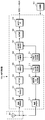
- FIG. 5 is a functional block diagram showing a configuration example of the terminal station apparatus 120a according to the first embodiment. Note that the example of the radio communication system in FIG. 1 corresponds to a configuration example of the terminal station apparatuses 120-1 to 120-8.
- the wireless reception unit 502 receives a signal from the relay station device through the antenna of the antenna unit 501.
- the GI removal unit 503 removes the GI from the received signal.
- the FFT unit 504 performs time-frequency conversion on the received signal from which the GI has been removed, using FFT or the like, and converts the received signal into received symbols for each subcarrier.
- the CRS separator 505 separates the CRS from the received symbol, inputs the separated CRS to the CRS propagation path estimator 512, and inputs the remaining received symbols to the DMRS separator 506.
- the CRS propagation path estimation unit 512 estimates the propagation path state between each antenna of the relay station apparatus and the antenna of the antenna unit 501 of the terminal station apparatus 120a based on the separated CRS.
- the terminal station CSI generating unit 513 generates CSI for notifying the relay station device of the CSI based on the channel state estimated by the CRS channel estimating unit 512.
- the radio transmission unit 514 transmits the CSI generated by the terminal station CSI generation unit 513 to the relay station apparatus through the antenna of the antenna unit 501.
- DMRS separation section 506 separates DMRS from the received symbol, inputs the separated DMRS to DMRS propagation path estimation section 511, and inputs the remaining reception symbols to propagation path compensation section 507.
- DMRS propagation path estimation section 511 estimates the propagation path state after precoding by the relay station apparatus based on the separated DMRS.
- the propagation path compensation unit 507 performs propagation path compensation (equalization) on the received symbols (symbols addressed to each terminal station apparatus) based on the estimation result of the propagation path state after precoding in the DMRS propagation path estimation unit 511. Do. Demodulation section 509 demodulates the received symbol whose propagation path has been compensated. If a modulation method is designated, demodulation is performed based on the modulation method.
- Decoding section 510 performs error correction decoding processing on the demodulated sequence, and generates and outputs a received data sequence.
- error correction decoding processing is performed after rate matching (depuncturing) is performed according to the coding rate.
- the control unit 515 controls each of the above units and causes each process to be executed.
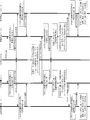
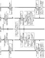
- FIG. 6 is a sequence diagram illustrating an example of a processing procedure between the base station device, the relay station device, and the terminal station device in the wireless communication system according to the present embodiment.
- base station apparatus 100 transmits CRS by multiplexing it with a broadcast signal (broadcast signal) or transmission data.
- each relay station apparatus estimates the propagation path state between each antenna of the base station apparatus 100 and each antenna of the own relay station apparatus based on the reception state of the CRS signal. Then, the relay station CSI representing the estimated propagation path state is generated and notified to the base station apparatus 100.
- each relay station device transmits the CRS to each terminal station device that is a relay transmission destination, for example, by multiplexing the transmission data.
- each terminal station apparatus receives the CRS signal from the relay station apparatus 110-1 or 110-2 as the relay transmission source
- each terminal station apparatus receives each antenna of the relay station apparatus as the relay transmission source based on the reception state of the CRS signal.
- the terminal station CSI representing the estimated channel state is generated and notified to the relay station device of each relay transmission source.
- Base station apparatus 100 performs error correction coding and modulation on each transmission data addressed to terminal station apparatuses 120-1 to 120-8, multiplexes DMRS, and performs linear precoding based on the latest relay station CSI. Do. Further, a transmission signal in which CRS is multiplexed is generated and simultaneously transmitted to each relay station apparatus by multiuser MIMO transmission.
- Each relay station apparatus separates and extracts the CRS in the received signal, estimates the propagation path state between each antenna of the base station apparatus 100 and each antenna of the own relay station apparatus based on the reception state of the CRS, and estimates The relay station CSI representing the transmitted channel state is generated and notified to the base station apparatus 100. Note that this relay station CSI notification may be performed after or before the subsequent multi-user MIMO transmission addressed to each terminal station apparatus.
- each relay station apparatus separates and extracts DMRS in the received signal, and performs channel compensation (equalization) on the data symbols in the received signal based on the extracted reception state of the DMRS. Further, each relay station device multiplexes DMRS on the propagation path compensation result, and performs linear precoding based on the latest terminal station CSI. Further, a transmission signal in which CRS is multiplexed is generated and simultaneously transmitted to each terminal station apparatus by multiuser MIMO transmission.
- Each terminal station apparatus separates and extracts the CRS from the received signal, and based on the reception status of the CRS, each antenna of the relay station apparatus 110-1 or 110-2 of each relay transmission source and each antenna of the own terminal station apparatus
- the terminal station CSI representing the estimated channel state is generated and notified to the relay station device of each relay transmission source.
- the notification of the terminal station CSI may be performed after or after the subsequent detection of data addressed to the own station.
- each terminal station apparatus separates and extracts DMRS in the received signal, performs propagation path compensation (equalization) on the data symbols in the received signal based on the extracted reception state of DMRS, and performs demodulation and error correction decoding. To detect the data addressed to your station.
- Multi-user MIMO transmission is performed using precoding that suppresses.
- transmission efficiency can be improved.
- the configuration of the base station apparatus in the second embodiment is the same as that of the base station apparatus 100 of FIG. 2 in the first embodiment, and the processing in the precoding unit 204 is different.
- description of the same parts as those in the first embodiment will be omitted, and the precoding unit 204 will be described.
- FIG. 7 is a functional block diagram showing a configuration example of the precoding unit 204 according to the first embodiment.
- the precoding unit of this configuration example is represented as a precoding unit 204b.
- the complex channel gain between each antenna of the base station apparatus 100 and each antenna of each relay station apparatus is notified as CSI from the relay station apparatus, and THP that is nonlinear precoding is used. A case where a precoding symbol is generated will be described.
- the QR decomposition unit 604 determines each antenna of the base station device 100 and each antenna of each relay station device from the relay station CSI notified from each relay station device acquired by the relay station CSI acquisition unit 211. Is generated for each subcarrier, and QR decomposition is performed on Hermitian conjugate H H of the channel matrix H. And it decomposes
- an interference matrix B (diagR H ) ⁇ 1 R H ⁇ I representing the gain of the MUI between the antennas of all relay station apparatuses is obtained and output to the interference component calculation unit 603, and the unitary matrix Q is converted to the linear filter unit 605. Output to.
- diagX is a matrix having only the diagonal component of the matrix X, and I represents a unit matrix.
- the interference matrix B takes the form of equation (3).
- the first modulo arithmetic unit 602-1 uses the modulo width predetermined by the modulation scheme for the modulation symbol addressed to the first terminal station device on which the DMRS is multiplexed by the DMRS multiplexing unit 203-1. To do. In addition, since there is no MUI for the modulation symbol addressed to the first terminal station apparatus, the interference component subtraction unit is omitted. Further, the modulo arithmetic unit 602-1 can be omitted.
- the interference component calculation unit 603 Based on the interference matrix B obtained by the QR decomposition unit 604, the interference component calculation unit 603 obtains the modulo operation result of the modulation symbol of each subcarrier addressed to the first terminal station device for each sub address addressed to the second terminal station device.
- the interference component given to the modulation symbol of the carrier is calculated.
- the element b 2,1 in the second row and first column of the interference matrix B represents the complex gain of interference that the modulation symbol addressed to the first terminal station apparatus has on the modulation symbol addressed to the second terminal station apparatus.
- the interference component can be calculated by multiplying this element by the modulo calculation result of the modulation symbol addressed to the first terminal station apparatus.
- the second interference component subtraction unit 601-2 calculates the second terminal station device calculated by the interference component calculation unit 603 from the modulation symbol addressed to the second terminal station device on which DMRS is multiplexed by the DMRS multiplexing unit 203-2.
- the interference component for the destination modulation symbol is subtracted for each subcarrier.
- the second modulo operation unit 602-2 performs a modulo operation on the modulation symbol addressed to the second terminal station apparatus from which the interference component has been subtracted, using a modulo width predetermined by the modulation method.
- the interference component calculation unit 603 determines that the modulo calculation result of the modulation symbol of each subcarrier addressed to the first terminal station apparatus and the modulo calculation result of the modulation symbol of each subcarrier addressed to the second terminal station apparatus are the third terminal
- the interference component given to the modulation symbol of each subcarrier addressed to the station apparatus is calculated.
- the element b 3,1 in the third row and first column of the interference matrix B represents the complex gain of interference that the modulation symbol addressed to the first terminal station apparatus has on the modulation symbol addressed to the third terminal station apparatus.
- the elements b 3, 2 in the third row and the second column of the interference matrix B represent the complex gain of interference exerted by the modulation symbol addressed to the second terminal station device on the modulation symbol addressed to the third terminal station device.
- the interference component can be calculated by multiplying these elements by the modulo operation result of the modulation symbol addressed to the first terminal station apparatus and the modulo operation result of the modulation symbol addressed to the second terminal station apparatus, respectively.
- the N-th interference component subtraction unit 601-N is configured to calculate the N-th terminal station device calculated by the interference component calculation unit 603 from the modulation symbol addressed to the N-th terminal station device on which DMRS is multiplexed by the DMRS multiplexing unit 203-2.
- the interference component for the destination modulation symbol is subtracted for each subcarrier.
- the Nth modulo arithmetic unit 602 -N performs modulo arithmetic on the modulation symbol addressed to the Nth terminal station apparatus from which the interference component has been subtracted, using a modulo width predetermined by the modulation scheme.
- the linear filter unit 605 receives the modulo operation results of the modulation symbols destined for the first to Nth terminal station apparatuses output from the first modulo operation unit 602-1 to the Nth modulo operation unit 602-N, respectively. Then, the unitary matrix Q calculated by the QR decomposition unit 604 is multiplied for each subcarrier as a linear filter. Then, precoding symbols to be transmitted are output from the antennas 209-1 to 209-N.
- each relay station apparatus when each relay station apparatus receives the precoding symbol, interference (MUI) due to a signal other than the own relay station apparatus is canceled by THP, and only the signal to be relayed by the own relay station apparatus is received. . Furthermore, according to the present embodiment, when each relay station apparatus receives the precoding symbol, transmission data modulation symbols destined for each terminal station apparatus to be relayed by each relay station apparatus are also individually separated without interference. Received in the state. As a result, the signal separation processing in the relay station device is not necessary, and the amount of computation of the relay station device can be reduced and the processing delay can be shortened. Furthermore, by using THP which is nonlinear precoding as precoding, MUI can be suppressed with high power efficiency, and transmission characteristics are improved.
- THP which is nonlinear precoding as precoding
- a method using QR decomposition of a channel matrix is exemplified as a method for realizing THP.
- the present invention is not limited to this, and V-BLAST (Vertical Bell Laboratories Layered Space Time)
- V-BLAST Very Bell Laboratories Layered Space Time
- a method described in Non-Patent Document 4 or the like that sub-optimizes the rearrangement of terminal station apparatuses in THP using a technique may be used.
- the configuration of the relay station device 110b in the second embodiment is such that modulo arithmetic units 408-1 to 408-M are added to the relay station device 110a of FIG. 3 of the first embodiment, and the precoding unit 411
- the processing is different and the other configurations are the same.
- description of the same parts as those of the first embodiment will be omitted, and different parts will be described.
- FIG. 8 is a functional block diagram showing a configuration example of the relay station apparatus 110b according to the second embodiment.
- the modulo arithmetic units 408-1 to 408-M are predetermined by the modulation scheme for the symbols for the respective channel-compensated terminals that are output from the channel compensation units 407-1 to 407-M. Modulo operation is performed using the modulo width.
- DMRS multiplexing sections 410-1 to 410-M multiplex DMRS to symbols addressed to each terminal station apparatus on which modulo operation has been performed.
- the DMRS is a known symbol that is referred to in order to perform propagation channel compensation and demodulation of the received signal in each terminal station apparatus.
- the multiplexed DMRS is precoded in the precoding unit 411 in the same manner as symbols destined for each terminal station apparatus. Further, multiplexing with DMRS may be performed by time division, for example, or may be performed by frequency division such as division by subcarriers.
- the configuration of the precoding unit 411 is the same as the precoding unit 204b (precoding unit 204b in FIG. 7) in the base station apparatus 100. However, the difference is that the terminal station CSI is used instead of the relay station CSI as the propagation path state information, and symbols addressed to the first to Mth terminal station apparatuses are input as inputs.
- the relay station apparatus can perform precoding for multi-user MIMO without performing demodulation and error correction decoding on the received symbol addressed to each terminal station apparatus to be subjected to relay transmission. Calculation amount and processing time can be reduced. Furthermore, by using THP which is nonlinear precoding as precoding, MUI can be suppressed with high power efficiency, and transmission characteristics are improved.
- the configuration of the terminal station device 120b in the second embodiment is different from the terminal station device 120a of FIG. 5 of the first embodiment in that a modulo arithmetic unit 508 is added, but the other configurations are the same as in the first embodiment. Is the same.
- description of the same parts as those of the first embodiment will be omitted, and different parts will be described.
- FIG. 9 is a functional block diagram showing a configuration example of the terminal station apparatus 120b according to the second embodiment.
- the modulo operation unit 508 performs modulo operation on the received channel-compensated reception symbol output from the propagation channel compensation unit 507 using a modulo width predetermined by the modulation scheme.
- the demodulator 509 demodulates the symbol on which the modulo operation has been performed.
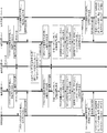
- FIG. 10 is a sequence diagram illustrating an example of a processing procedure between the base station apparatus, the relay station apparatus, and the terminal station apparatus in the wireless communication system according to the present embodiment.
- base station apparatus 100 transmits CRS by multiplexing it with a broadcast signal (broadcast signal) or transmission data.
- each relay station apparatus When each relay station apparatus receives CRS from base station apparatus 100, each relay station apparatus estimates a propagation path state between each antenna of base station apparatus 100 and each antenna of its own relay station apparatus based on the reception state of the CRS signal. . Then, relay station CSI representing the estimated propagation path state is generated and notified to base station apparatus 100.
- each relay station device transmits the CRS to each terminal station device that is a relay transmission destination, for example, by multiplexing the transmission data.
- each terminal station apparatus receives the CRS signal from the relay station apparatus 110-1 or 110-2 as the relay transmission source
- each terminal station apparatus receives each antenna of the relay station apparatus as the relay transmission source based on the reception state of the CRS signal. And the state of the propagation path between each antenna of the terminal apparatus and the terminal apparatus. And the terminal station CSI showing the estimated propagation path state is produced
- the base station apparatus 100 performs error correction coding and modulation on each transmission data addressed to the terminal station apparatuses 120-1 to 120-8, multiplexes DMRS, and performs nonlinear precoding by THP based on the latest relay station CSI. Do coding. Further, a transmission signal in which CRS is multiplexed is generated and simultaneously transmitted to each relay station apparatus by multiuser MIMO transmission.
- Each relay station apparatus separates and extracts the CRS in the received signal, estimates the propagation path state between each antenna of the base station apparatus 100 and each antenna of the own relay station apparatus based on the reception state of the CRS, and estimates The relay station CSI representing the transmitted channel state is generated and notified to the base station apparatus 100. Note that this relay station CSI notification may be performed after or before the subsequent multi-user MIMO transmission addressed to each terminal station apparatus.
- each relay station apparatus separates and extracts DMRS in the received signal, and performs channel compensation (equalization) on the data symbols in the received signal based on the extracted reception state of the DMRS. Furthermore, each relay station apparatus performs a modulo operation on the propagation path compensation result.
- each relay station device multiplexes DMRS to the received symbol of the modulo calculation result, and performs nonlinear precoding by THP based on the latest terminal station CSI. Further, a transmission signal in which CRS is multiplexed is generated and simultaneously transmitted to each terminal station apparatus by multiuser MIMO transmission.
- Each terminal station apparatus separates and extracts the CRS from the received signal, and based on the reception status of the CRS, each antenna of the relay station apparatus 110-1 or 110-2 of each relay transmission source and each antenna of the own terminal station apparatus Is estimated. And the terminal station CSI showing the estimated propagation path state is produced
- the notification of the terminal station CSI may be performed after or after the subsequent detection of data addressed to the own station.
- each terminal station apparatus separates and extracts the DMRS in the received signal, and performs channel compensation (equalization) on the data symbols in the received signal based on the reception state of the extracted DMRS. Then, after further modulo operation, demodulation and error correction decoding are performed to detect data addressed to the own station.
- the MUI between the relay station apparatuses and the MUI between the signals addressed to the terminal station apparatuses received by the respective antennas from the base station apparatus to the plurality of relay station apparatuses Multi-user MIMO transmission is performed using precoding that suppresses. Then, precoding for suppressing the MUI between the terminal station apparatuses is performed on the received symbol that has been subjected only to propagation path compensation in the relay station apparatus, and multi-user MIMO transmission is performed to each terminal station apparatus. As a result, transmission efficiency can be improved. Furthermore, by using THP which is nonlinear precoding as the precoding, MUI can be suppressed with high power efficiency, and transmission characteristics are further improved.
- the configuration of the relay station device 110c in the third embodiment is the same as the relay station device 110b in FIG. 8 in the second embodiment except that temporary determination units 409-1 to 409-M are added. It is.
- description of the same parts as those of the second embodiment will be omitted, and different parts will be described.
- FIG. 11 is a functional block diagram illustrating a configuration example of the relay station device 110c according to the third embodiment.
- Temporary determination sections 409-1 to 409-M each receive a signal point (reception signal point) and a signal point (modulation signal point) determined by the modulation method for each symbol addressed to each terminal station apparatus on which modulo operation has been performed. ) To estimate the transmission signal point. Then, a new symbol addressed to each terminal station apparatus is generated at the estimated signal point (provisional determination signal point).
- FIG. 12 is a conceptual diagram showing an example of temporary determination in the temporary determination units 409-1 to 409-M.
- the horizontal axis indicates the I-axis of the in-phase component of the signal
- the vertical axis indicates the Q-axis of the quadrature component
- 16-value quadrature amplitude modulation (16 Quadrature Amplitude Modulation: 16QAM) is used as the modulation method.
- 16QAM 16 Quadrature Amplitude Modulation
- DMRS multiplexing sections 410-1 to 410-M receive DMRSs, which are known symbols to be referred to in order to perform propagation channel compensation and demodulation of received signals in each terminal station apparatus, in temporary determination sections 409-1 to 409-M. Multiplexing is performed on the generated symbols addressed to each terminal station device.
- the multiplexed DMRS is precoded in the precoding unit 411 in the same manner as symbols destined for each terminal station apparatus. Further, multiplexing with DMRS may be performed by time division, for example, or may be performed by frequency division such as division by subcarriers.
- the relay station apparatus does not perform error correction decoding on the received symbol addressed to each terminal station apparatus to be subjected to relay transmission, and performs a provisional determination of a received signal point with a smaller amount of computation. Precoding for multi-user MIMO can be performed, and the amount of computation and processing time of the relay station apparatus can be reduced.
- FIG. 13 is a sequence diagram illustrating an example of a processing procedure between the base station device, the relay station device, and the terminal station device in the wireless communication system according to the present embodiment.
- base station apparatus 100 transmits CRS by multiplexing it with a broadcast signal (broadcast signal) or transmission data.
- each relay station apparatus When each relay station apparatus receives the CRS from the base station apparatus 100, each relay station apparatus estimates the propagation path state between each antenna of the base station apparatus 100 and each antenna of the own relay station apparatus based on the reception state of the CRS signal. Then, the relay station CSI representing the estimated propagation path state is generated and notified to the base station apparatus 100. Also, each relay station device transmits the CRS to each terminal station device that is a relay transmission destination, for example, by multiplexing the transmission data.
- each terminal station apparatus When each terminal station apparatus receives the CRS signal from the relay station apparatus 110-1 or 110-2 as the relay transmission source, each terminal station apparatus receives each antenna of the relay station apparatus as the relay transmission source based on the reception state of the CRS signal. And the terminal station CSI representing the estimated channel state is generated and notified to the relay station device of each relay transmission source.
- the base station apparatus 100 performs error correction coding and modulation on each transmission data addressed to the terminal station apparatuses 120-1 to 120-8, multiplexes DMRS, and performs nonlinear precoding by THP based on the latest relay station CSI. Do coding. Further, a transmission signal in which CRS is multiplexed is generated and simultaneously transmitted to each relay station apparatus by multiuser MIMO transmission.
- Each relay station apparatus separates and extracts the CRS in the received signal, estimates the propagation path state between each antenna of the base station apparatus 100 and each antenna of the own relay station apparatus based on the reception state of the CRS, and estimates The relay station CSI representing the transmitted channel state is generated and notified to the base station apparatus 100. Note that this relay station CSI notification may be performed after or before the subsequent multi-user MIMO transmission addressed to each terminal station apparatus.
- each relay station apparatus separates and extracts DMRS in the received signal, and performs channel compensation (equalization) on the data symbols in the received signal based on the extracted reception state of the DMRS. Furthermore, each relay station apparatus performs a modulo operation on the propagation path compensation result. Furthermore, each relay station apparatus performs provisional determination on the received symbol of the modulo calculation result, and regenerates the data symbol.
- Each relay station device multiplexes DMRS with the symbol of the provisional determination result, and performs nonlinear precoding by THP based on the latest terminal station CSI. Further, a transmission signal in which CRS is multiplexed is generated and simultaneously transmitted to each terminal station apparatus by multiuser MIMO transmission.
- Each terminal station apparatus separates and extracts the CRS from the received signal, and based on the reception status of the CRS, each antenna of the relay station apparatus 110-1 or 110-2 of each relay transmission source and each antenna of the own terminal station apparatus
- the terminal station CSI representing the estimated channel state is generated and notified to the relay station device of each relay transmission source.
- the notification of the terminal station CSI may be performed after or after the subsequent detection of data addressed to the own station.
- each terminal station apparatus separates and extracts the DMRS in the received signal, performs channel compensation (equalization) on the data symbol in the received signal based on the extracted reception state of the DMRS, and further performs a modulo operation. Then, demodulation and error correction decoding are performed to detect data addressed to the own station.
- the MUI between the relay station apparatuses and the MUI between the signals addressed to the terminal station apparatuses received by the respective antennas from the base station apparatus to the plurality of relay station apparatuses Precoding that suppresses MUI between each terminal station apparatus is performed on the received symbol that has been subjected to multi-user MIMO transmission using precoding that suppresses, and that has only undergone propagation path compensation and provisional determination of received signal points in the relay station apparatus.
- multi-user MIMO transmission can be performed for each terminal station apparatus, and transmission efficiency can be improved.
- THP that is nonlinear precoding
- the relay station apparatus performs provisional determination, the reception error rate in each terminal station apparatus can be reduced.
- the base station apparatus 100 communicates with a plurality of terminal station apparatuses (for example, first to eighth terminal station apparatuses 120-1 to 120-8).
- a plurality of relay station devices for example, the first relay station device 110-1 and the second relay station device 110-2 are passed once to spatially transmit data addressed to each terminal station device.
- a radio communication system that performs multi-user MIMO transmission that performs multiplexing and simultaneous communication is described.
- a radio communication system that performs multi-user MIMO transmission in which transmission data addressed to each terminal station apparatus is spatially multiplexed and simultaneously communicated via a relay station apparatus at least twice in a hierarchical manner explain.
- FIG. 14 is a diagram illustrating a schematic configuration example of a wireless communication system according to the fourth embodiment.
- transmission data addressed to the first terminal station apparatus 120-1 and the second terminal station apparatus 120-2 passes through the fifth relay station apparatus 110-5.
- the transmission data addressed to the third terminal station device 120-3 and the fourth terminal station device 120-4 passes through the sixth relay station device 110-6.
- Transmission data addressed to the fifth terminal station device 120-5 and the sixth terminal station device 120-6 passes through the seventh relay station device 110-7.
- Transmission data addressed to the seventh terminal station device 120-7 and the eighth terminal station device 120-8 passes through the eighth relay station device 110-8. In this way, transmission data is transmitted.
- transmission data that passes through the fifth relay station device 110-5 and the sixth relay station device 110-6 are transmitted via the third relay station device 110-3. Further, transmission data that passes through the seventh relay station device 110-7 and the eighth relay station device 110-8 are transmitted via the fourth relay station device 110-4.
- the base station device 100 and the terminal station devices 120-1 to 120-8 in the fourth embodiment can be realized by any configuration in the above embodiments.
- the configurations of relay station apparatuses 110-3 and 110-4 are the same as those of the relay station apparatuses in the above embodiments.
- the relay station CSI indicating the propagation path state between each relay station apparatus at the next stage of the relay transmission destination is notified from each relay station apparatus at the next stage, and precoding is performed based on the relay station CSI. The point to do is different.
- relay station apparatuses 110-5 to 110-8 is the same as that of the relay station apparatus in each of the above embodiments. However, the difference is that the number of antennas is different, and the relay station CSI is notified of the CSI representing the propagation path state with the relay station apparatus at the previous stage of the relay transmission source to the relay station apparatus at the previous stage.
- each branch has the same number of hierarchies and includes the same number of relay station apparatuses and terminal station apparatuses, but the embodiment is limited to this. Instead, the number of layers may be different in each branch, and the number of relay station apparatuses and terminal station apparatuses included may be different.
- a transmission signal from a base station apparatus is simultaneously transmitted to a plurality of terminal station apparatuses that are relay-transmitted a plurality of times (a plurality of layers) by different relay station apparatuses using spatial multiplexing in each layer Transmission efficiency can be improved.
- transmission from the base station apparatus is always relayed to the terminal station apparatus by the relay station apparatus.
- the present invention is not limited to this, and some terminal station apparatuses directly communicate with the base station apparatus.
- a form for performing communication may be used.
- the base station apparatus receives the terminal station CSI of the terminal station apparatus, and simultaneously transmits transmission signals to the relay station apparatus and the terminal station apparatus based on the relay station CSI and the terminal station CSI by multiuser MIMO. To do.
- multi-user MIMO transmission using the same precoding scheme is performed in each transmission from the base station device to the relay station device, from the relay station device to the relay station device, and from the relay station device to the terminal station device.
- nonlinear precoding such as THP is used in multiuser MIMO transmission from a base station apparatus to a relay station apparatus and relay station apparatus to relay station apparatus
- linear precoding is used in multiuser MIMO transmission from a relay station apparatus to a terminal station apparatus. May be.
- linear precoding based on detailed CSI is used for multi-user MIMO transmission from the base station apparatus to the relay station apparatus and from the relay station apparatus to the relay station apparatus
- PMI is used for multi-user MIMO transmission from the relay station apparatus to the terminal station apparatus.
- Different precoding schemes may be used, such as based beamforming.
- the program that operates in the communication device according to the present invention may be a program that controls a CPU (Central Processing Unit) or the like (a program that causes a computer to function) so as to realize the functions of the above-described embodiments related to the present invention.
- Information handled by these devices is temporarily stored in RAM (Random Access Memory) during processing, and then stored in various ROMs such as Flash ROM (Read Only Memory) and HDD (Hard Disk Drive). Reading, correction, and writing are performed by the CPU as necessary.
- the “computer system” includes an OS and hardware such as peripheral devices.
- the “computer-readable recording medium” means a storage device such as a flexible disk, a magneto-optical disk, a portable medium such as a ROM and a CD-ROM, and a hard disk incorporated in a computer system. Furthermore, the “computer-readable recording medium” dynamically holds a program for a short time like a communication line when transmitting a program via a network such as the Internet or a communication line such as a telephone line. In this case, a volatile memory in a computer system serving as a server or a client in that case, and a program that holds a program for a certain period of time are also included.
- the program may be a program for realizing a part of the functions described above, and may be a program capable of realizing the functions described above in combination with a program already recorded in a computer system.
- part or all of the communication devices in the above-described embodiment may be realized as an LSI that is typically an integrated circuit.
- Each functional block of the communication device may be individually chipped, or part or all of them may be integrated into a chip.
- the method of circuit integration is not limited to LSI, and may be realized by a dedicated circuit or a general-purpose processor.
- an integrated circuit based on the technology can also be used.
- Base station device 110, 110-1 to K, 110a to c Relay station device 120, 120-1 to M, 120a to b Terminal station device (wireless receiving device) 201-1 to N Encoding unit 202-1 to N Modulation unit 203-1 to N DMRS multiplexing unit 204, 204a to b Precoding unit 205-1 to N CRS multiplexing unit 206-1 to N IFFT unit 207-1 to N GI insertion unit 208-1 to N Radio transmission unit 209-1 to N Antenna unit 210 Radio reception unit 211 Relay station CSI acquisition unit 212 Control unit 301 Filter calculation unit 302 Linear filter unit 401-1 to M Antenna unit 402-1 M receiver unit 403-1 to M GI removing unit 404-1 to M FFT unit 405-1 to M CRS separating unit 406-1 to M DMRS separating unit 407-1 to M propagation path compensating unit 408-1 to M Modulo arithmetic unit 409-1 to M Temporary determination unit 410-1
Landscapes
- Engineering & Computer Science (AREA)
- Computer Networks & Wireless Communication (AREA)
- Signal Processing (AREA)
- Radio Transmission System (AREA)
- Radio Relay Systems (AREA)
- Mobile Radio Communication Systems (AREA)
Abstract
送信信号を異なる中継局装置を介して中継伝送する場合に、空間多重を用いて同時に伝送することが可能となり、伝送効率を向上させる。中継局装置110-1、110-2は、マルチユーザMIMO伝送により複数のデータ系列を中継する。推定された自中継局装置110-1、110-2と中継元100との間の伝搬路状態を示す第1のCSIを生成し、中継元100へ送信する。第1のCSIに基づいてプリコーディングがなされ、中継元100から同時に複数の中継局装置110-1、110-2に送信されたデータ系列のうち、受信されたデータ系列に対して、伝搬路補償後に、推定された自無線中継装置110-1、110-2と複数の中継先120-1~8のそれぞれとの間の伝搬路状態を示す第2のCSIに基づいてプリコーディングを行ない、複数の中継先120-1~8へ同時にデータ系列を送信する。
Description
本発明は、干渉を信号処理によって予め抑圧して送受信する無線中継装置、無線送信装置、無線受信装置、無線通信システム、制御プログラムおよび集積回路に関する。
送受信に複数のアンテナを使用し、同じ周波数帯域で複数の異なるデータ系列(データストリーム)を空間的に多重して同時通信するMIMO(Multiple-Input Multiple-Output:多入力多出力)伝送技術が、無線LANやセルラシステムなどで実用化されている。複数の異なるデータ系列を空間多重して、ある1つの端末局装置に伝送するシングルユーザMIMO(Single User MIMO)では、端末局装置における複数のデータ系列の分離・検出の性能を向上させるために、基地局装置において送信信号にプリコーディングを行なってから送信する方法がある。
また、次世代のセルラシステム等において、基地局装置(無線送信装置)の備える送信アンテナ数が端末局装置(無線受信装置)の備える受信アンテナ数に比べて大幅に多くなるシステムが提案されている。このようなシステムにおいて、基地局装置の送信アンテナを有効に活用してさらにシステムスループットを向上させるために、複数の端末局装置(ユーザ)宛のデータ系列をMIMO多重するマルチユーザMIMO(Multi-User MIMO)が提案されている。しかしながら、マルチユーザMIMOにおいて多重された信号を受信する複数の端末局装置の間では、他の端末が受信した信号を知ることはできないため、そのままでは各ユーザ宛のストリーム間で生じるユーザ間干渉(Multi-User Interference:MUI)により大幅に特性が劣化してしまう。
これに対して、端末局装置における受信時にMUIを抑圧する送信信号を生成する幾つかの方法が提案されている(非特許文献1)。基地局装置の各送信アンテナから各端末局装置の各受信アンテナまでのチャネル状態情報であるCSI(Channel State Information)を基地局装置が知っていれば、端末局装置に大きな負荷を掛けることなく端末局装置における受信時にMUIを抑圧できる送信信号を生成することができる。このような方法には、例えば、端末局装置における受信時にMUIが抑圧された状態で受信できるように、基地局装置において送信信号にプリコーディングを行なってから送信する方法がある。
その例として、CSIより求めた各送信アンテナと各端末局装置の各受信アンテナとの間の複素伝搬路利得を要素に持つチャネル行列Hから、その逆行列H-1(または擬似逆行列H†=HH(HHH)-1:上付き添え字のHはエルミート共役を表す)を重み行列(線形フィルタ)Wとして用いて送信信号に重み付け(W=H-1を送信信号に乗算)するZero-forcing(ZF)プリコーディングがある。また、最小平均二乗誤差(Minimum Mean Square Error:MMSE)規範で求めた重み行列(線形フィルタ)W=HH(HHH+αI)-1(Iは単位行列、αは正規化係数を表す)で送信信号を重み付けするMMSEプリコーディングなどの、線形処理によって送信信号をプリコーディングする線形プリコーディング(ビームフォーミング)がある。
そして、他の例として、非線形プリコーディングがある。非線形プリコーディングでは、CSIより求めた干渉信号成分を送信信号から予め減算し、信号空間の中で送信電力が低減されるような信号点に干渉減算後の信号を符号化する非線形処理によって送信信号をプリコーディングする。その結果、干渉減算後に増加する送信電力を抑圧できる。この非線形プリコーディングの1つとして、送受信装置双方で信号に対してモジュロ(Modulo、剰余)演算を行なうことによって、送信電力の増加を抑圧することが可能なトムリンソン-ハラシマ・プリコーディング(Tomlinson-Harashima Precoding:THP)が提案されている(非特許文献2、非特許文献3、非特許文献4)。このとき、受信側である端末局装置においても、受信信号に対して送信と同様のモジュロ演算を行なう。ここでモジュロ幅τによるモジュロ演算Modτは、送信側における干渉減算後の信号または受信側における受信信号を表す複素ベクトルをνとしたとき、式(1)で表される。なお、jは虚数単位、floor(a)はaを超えない最大の整数を表し、Re(ν)およびIm(ν)はそれぞれ複素数νの実部(信号の同相成分に相当)と虚部(信号の直交成分に相当)を表す。なおここでの非線形処理とは、主に、モジュロ演算等の出力に不連続点が存在する処理を用いたものを言う。

別の無線通信技術として、基地局装置と端末局装置との間の無線信号を中継伝送する中継技術(リレー技術)が、セルラシステムにおけるセル周辺部ユーザのスループット向上を目的として検討されている。無線信号を中継する中継技術として、中継局装置(無線中継装置)において基地局装置からの受信信号を電力増幅して端末局装置へ再送信するAF(Amplify and Forward)型の中継技術と、中継局装置において基地局装置からの受信信号に対して一度復調および誤り訂正復号まで行ない、再度誤り訂正符号化および変調を行なって端末局装置へ再送信するDF(Decode and Forward)型の中継技術などがある。AF型では、中継局装置で受信された他セルからの干渉信号や雑音も電力増幅されるため伝送特性が劣化してしまう。一方、DF型では、中継局装置における変復調および誤り訂正符号化・復号処理に伴い、演算量と処理遅延が増大してしまう。
このように、マルチユーザMIMO伝送と中継技術を組み合わせて、単一の基地局装置から単一の中継局装置に対してシングルユーザMIMO伝送し、中継局装置から複数の端末局装置に対してマルチユーザMIMO伝送を行なう方法が提案されている(非特許文献5)。
Spencer他、「An Introduction to the Multi-User MIMO Downlink」、IEEE Communication Magazine、Vol.42、Issue10、p.60-67、2004年10月
Harashima他、「Matched-Transmission Technique for Channels With Intersymbol Interference」、IEEE Transaction on Communications、Vol.COM-20、No.4、p.774-780、1972年8月
J.Liu他、「Improved Tomlinson-Harashima Precoding for the Downlink of Multiple Antenna Multi-User Systems」、Proc. IEEE Wireless and Communications and Networking Conference、p.466-472、2005年3月
M.Joham他、「MMSE Approaches to Multiuser Spatio-Temporal Tomlinson-Harashima Precoding」、Proc. 5th Int. ITG Conf. on Source and Channel Coding、p.387-394、2004年1月
C.B.Chae他、「MIMO Relaying With Linear Processing for Multiuser Transmission in Fixed Relay Networks」、IEEE Transaction on Signal Processing、Vol.56、No.2、p.727-738、2008年2月
しかしながら、従来のマルチユーザMIMO伝送と中継技術を組み合わせた伝送方法では、基地局装置からの送信信号を異なる中継局装置を介して複数の端末局装置に対して中継伝送する場合に、空間多重を用いて同時に伝送することはできなかった。
本発明は、このような事情に鑑みてなされたものであり、送信信号を異なる中継局装置を介して中継伝送する場合に、空間多重を用いて同時に伝送することが可能となり、伝送効率を向上させることができる無線中継装置、無線送信装置、無線受信装置、無線通信システム、制御プログラムおよび集積回路を提供することを目的とする。
(1)上記の目的を達成するために、本発明は、以下のような手段を講じた。すなわち、本発明の無線中継装置は、マルチユーザMIMO伝送により複数のデータ系列を中継する無線中継装置であって、推定された自無線中継装置と中継元との間の伝搬路状態を示す第1のCSIを生成する第1のCSI生成部と、前記第1のCSIを前記中継元へ送信する無線送信部と、推定された自無線中継装置と複数の中継先のそれぞれとの間の伝搬路状態を示す第2のCSIを取得する第2のCSI取得部と、前記第1のCSIに基づいてプリコーディングがなされ、前記中継元から同時に複数の無線中継装置に送信されたデータ系列のうち、受信されたデータ系列に対して、伝搬路補償後に、前記取得された第2のCSIに基づいてプリコーディングを行なうプリコーディング部と、を備え、前記プリコーディングが行なわれたデータ系列を前記複数の中継先へ同時に送信することを特徴とする。
これにより、無線送信装置からの送信信号を異なる無線中継装置を介して複数の無線受信装置に対して中継伝送する場合に、空間多重を用いて同時に伝送することが可能となり、伝送効率を向上させることができる。なお、1階層の無線中継装置のみが中継伝送を行なう無線通信システムでは、「第1のCSI」は、「中継局CSI」に相当し、「第2のCSI」は、「端末局CSI」に相当する。また、たとえば「第1のCSI生成部」は、「中継局CSI生成部」に相当する。また、「中継元」は、「無線送信装置」に、「中継先」は、「無線受信装置」に相当する。複数階層の無線中継装置が中継伝送を行なう場合には、「中継元」または「中継先」の少なくとも一方が、「無線中継装置」に相当する。
(2)また、本発明の無線中継装置は、前記プリコーディング部が、前記中継元から送信されたデータ系列に対して、非線形プリコーディングを行なうことを特徴とする。
このように、非線形プリコーディングであるTHPを用いることにより、電力効率良くMUIを抑圧でき、さらに伝送特性が向上する。
(3)また、本発明の無線中継装置は、前記プリコーディング部が、前記中継元から送信されたデータ系列に対して、受信信号点の仮判定を行った後にプリコーディングを行なうことを特徴とする。
このように無線中継装置では、中継伝送の対象である各無線受信装置宛の受信シンボルについて誤り訂正復号は行わず、より演算量の小さい、受信信号点の仮判定を行なう。そして、仮判定上でマルチユーザMIMOのためのプリコーディングを行なうことが可能となり、無線中継装置の演算量と処理時間を縮小できる。
(4)また、本発明の無線送信装置は、マルチユーザMIMO伝送により複数のデータ系列を送信する無線送信装置であって、推定された自無線送信装置と複数の無線中継装置のそれぞれとの間の伝搬路状態を示す中継局CSIを取得する中継局CSI取得部と、前記取得された中継局CSIに基づいて、複数のデータ系列に対してプリコーディングを行なうプリコーディング部と、を備え、前記プリコーディングが行なわれたデータ系列を前記複数の無線中継装置へ同時に送信することを特徴とする。
これにより、プリコーディングシンボルを各無線中継装置が受信した場合、自無線中継装置以外への信号による干渉(MUI)がキャンセルされて自無線中継装置が中継すべき信号のみが受信される。また、プリコーディングシンボルを各無線中継装置が受信した場合、各無線中継装置が中継伝送すべき各無線受信装置宛の送信データ変調シンボル間も干渉無く個々に分離された状態で受信される。その結果、無線中継装置における信号分離処理が不要となり、無線中継装置の演算量を削減し、処理遅延を短縮できる。
また、送信データの最終的な受信主体である各無線受信装置は、無線中継装置よりも多数存在する。無線送信装置では、この各無線受信装置との間の伝搬路状態を知る必要がなく、各無線中継装置との間の伝搬路状態を知っていれば良く、無線送信装置に通知されるCSIの情報量を削減することができる。さらに、一般的に無線中継装置は準静止状態であることが多く、伝搬路の時間変動が緩やかであるため、各無線中継装置から通知される中継局CSIの通知頻度を、端末局CSIの通知頻度と比べて大幅に削減できる。
(5)また、本発明の無線送信装置は、前記プリコーディング部が、前記複数のデータ系列に対して非線形プリコーディングを行なうことを特徴とする。
このように、非線形プリコーディングであるTHPを用いることにより、電力効率良くMUIを抑圧でき、さらに伝送特性が向上する。
(6)また、本発明の無線受信装置は、上記(1)記載の無線中継装置を介して、マルチユーザMIMO伝送がなされたデータ系列を受信する無線受信装置であって、前記第2のCSIを生成する第2のCSI生成部と、前記第2のCSIを前記無線中継装置へ送信する無線送信部と、を備え、前記無線中継装置で前記第2のCSIに基づいてプリコーディングが行なわれ、同時に複数の無線受信装置へ送信されたデータ系列を受信することを特徴とする。
このように、無線送信装置から複数の無線中継装置に対して、無線中継装置間のMUIおよび各アンテナで受信される各無線受信装置宛の信号間のMUIを抑圧するプリコーディングを用いてマルチユーザMIMO伝送を行なうことができる。そして、無線中継装置において伝搬路補償のみを行った受信したシンボルに各無線受信装置間のMUIを抑圧するプリコーディングを行なって各無線受信装置に対してマルチユーザMIMO伝送を行うことが可能となり、伝送効率を向上させることができる。
(7)また、本発明の無線通信システムは、中継によりマルチユーザMIMO伝送を行なう無線通信システムであって、推定された自無線送信装置と複数の無線中継装置のそれぞれとの間の伝搬路状態を示す中継局CSIに基づいて、複数のデータ系列に対してプリコーディングを行ない、前記プリコーディングが行なわれたデータ系列を前記複数の無線中継装置へ同時に送信する無線送信装置と、推定された自無線中継装置と中継元との間の伝搬路状態を示す第1のCSIを生成して前記中継元へ送信し、前記無線送信装置から送信されたデータ系列に由来し、前記第1のCSIに基づいてプリコーディングがなされ、前記中継元から同時に複数の無線中継装置に送信されたデータ系列のうち、受信されたデータ系列に対して、推定された自無線中継装置と複数の中継先のそれぞれとの間の伝搬路状態を示す伝搬路状態を示す第2のCSIに基づいてプリコーディングを行ない、前記受信され、プリコーディングが行なわれたデータ系列を前記複数の中継先へ同時に送信する無線中継装置と、前記第2のCSIを生成して、受信されるデータ系列の送信元へ送信し、前記無線中継装置で中継されたデータ系列に由来し、前記受信されるデータ系列の送信元で前記第2のCSIに基づいてプリコーディングが行なわれ、同時に複数の無線受信装置へ送信されたデータ系列を受信する無線受信装置と、を備えることを特徴とする。
これにより、無線送信装置からの送信信号を異なる無線中継装置を介して複数の無線受信装置に対して中継伝送する場合に、空間多重を用いて同時に伝送することが可能となり、伝送効率を向上させることができる。
(8)また、本発明の無線通信システムは、前記無線送信装置から前記無線受信装置まで複数階層の無線中継装置を経由してマルチユーザMIMO伝送を行なうことを特徴とする。
これにより、無線送信装置からの送信信号を異なる無線中継装置によって複数回(複数階層)にわたって中継伝送される複数の無線受信装置に対して、各階層において空間多重を用いて同時に伝送することが可能となり、伝送効率を向上させることができる。
(9)また、本発明の制御プログラムは、マルチユーザMIMO伝送により複数のデータ系列の中継を制御する制御プログラムであって、推定された、制御される無線中継装置と中継元との間の伝搬路状態を示す第1のCSIを生成する処理と、前記第1のCSIを前記中継元へ送信する処理と、推定された前記制御される無線中継装置と複数の中継先のそれぞれとの間の伝搬路状態を示す第2のCSIを取得する処理と、前記第1のCSIに基づいてプリコーディングがなされ、前記中継元から同時に複数の無線中継装置に送信されたデータ系列のうち、受信されたデータ系列に対して、伝搬路補償後に、前記取得された第2のCSIに基づいてプリコーディングを行なう処理と、前記プリコーディングが行なわれたデータ系列を前記複数の中継先へ同時に送信する処理と、を含む一連の処理を、前記制御される無線中継装置に実行させることを特徴とする。
これにより、無線送信装置からの送信信号を異なる無線中継装置を介して複数の無線受信装置に対して中継伝送する場合に、空間多重を用いて同時に伝送することが可能となり、伝送効率を向上させることができる。
(10)また、本発明の集積回路は、マルチユーザMIMO伝送により複数のデータ系列の中継を制御する集積回路であって、推定された、制御される無線中継装置と中継元との間の伝搬路状態を示す第1のCSIを生成する機能と、前記第1のCSIを前記中継元へ送信する機能と、推定された前記制御される無線中継装置と複数の中継先のそれぞれとの間の伝搬路状態を示す第2のCSIを取得する機能と、前記第1のCSIに基づいてプリコーディングがなされ、前記中継元から同時に複数の無線中継装置に送信されたデータ系列のうち、受信されたデータ系列に対して、伝搬路補償後に、前記取得された第2のCSIに基づいてプリコーディングを行なう機能と、前記プリコーディングが行なわれたデータ系列を前記複数の中継先へ同時に送信する機能と、を含む一連の機能を、前記制御される無線中継装置に発揮させることを特徴とする。
これにより、無線送信装置からの送信信号を異なる無線中継装置を介して複数の無線受信装置に対して中継伝送する場合に、空間多重を用いて同時に伝送することが可能となり、伝送効率を向上させることができる。
本発明によれば、基地局装置からの送信信号を異なる中継局装置を介して複数の端末局装置に対して中継伝送する場合に、空間多重を用いて同時に伝送することが可能となり、伝送効率を向上させることができる。
以下に、本発明の実施形態について図面を参照しながら説明する。
図1は、各実施形態に係る無線通信システムの概略構成例を示す図である。図1に示すように、各実施形態における無線通信システムでは、基地局装置100が複数の端末局装置(例えば、第1から第8までの端末局装置120-1から120-8)と通信する。その場合の下りリンクの伝送において、複数の中継局装置(例えば、第1の中継局装置110-1および第2の中継局装置110-2)を経由して、各端末局装置宛の送信データを空間的に多重して同時通信するマルチユーザMIMO伝送を行なう。
図1の例では、第1の端末局装置120-1から第4の端末局装置120-4宛の送信データは第1の中継局装置110-1を経由し、第5の端末局装置120-5から第8の端末局装置120-8宛の送信データは第2の中継局装置110-2を経由して伝送される。
この場合に、基地局装置100は、基地局装置100の各アンテナと各中継局装置110-1、110-2の各アンテナとの間の伝搬路の状態(各アンテナ間の複素伝搬路利得、伝搬路の共分散行列など)や、その伝搬路状態から求めた所望プリコーディング行列のインデックス(Precoding Matrix Index:PMI)などを表す伝搬路状態情報(Channel State Information:CSI)に基づいて、第1の中継局装置110-1への送信信号と第2の中継局装置110-2への送信信号とが互いにユーザ間干渉(MUI)とならないようにプリコーディングを行ない、マルチユーザMIMO伝送を行なう。
さらに、第1の中継局装置110-1は、第1の中継局装置110-1の各アンテナと中継伝送先の第1の端末局装置120-1から第4の端末局装置120-4の各アンテナとの間のCSIに基づいて、第1の中継局装置110-1から各端末局装置への各送信信号が互いにMUIとならないようにプリコーディングを行ない、マルチユーザMIMO伝送を行なう。
同様に、第2の中継局装置110-2は、第2の中継局装置110-2の各アンテナと中継伝送先の第5の端末局装置120-5から第8の端末局装置120-8の各アンテナとの間のCSIに基づいて、第2の中継局装置110-2から各端末局装置への各送信信号が互いにMUIとならないようにプリコーディングを行ない、マルチユーザMIMO伝送を行なう。
なお、伝送方式として直交周波数分割多重(Orthogonal Frequency Division Multiplexing:OFDM)を用いた無線通信システムを例として説明するが、これに限られるものではない。
(第1の実施形態)
本実施形態では、基地局装置が、複数の端末局装置の中から、第1の端末局装置から第Nの端末局装置までのN個の端末局装置を選択して、K個の中継局装置を経由してデータを伝送する無線通信システムを例として説明する。
本実施形態では、基地局装置が、複数の端末局装置の中から、第1の端末局装置から第Nの端末局装置までのN個の端末局装置を選択して、K個の中継局装置を経由してデータを伝送する無線通信システムを例として説明する。
また、基地局装置はN本のアンテナを備え、K個の各中継局装置はそれぞれM本のアンテナを備え、N個の各端末局装置はそれぞれ1本のアンテナを備える(N=M×K)場合を例として説明するが、これに限られるものではない。なお、この場合、図1の無線通信システムの例では、K=2、M=4、N=8である。
図2は、第1の実施形態に係る基地局装置100の一構成例を示す機能ブロック図である。無線受信部210は、アンテナ部209-1から209-NのN本のアンテナのうちの少なくとも1本以上を用いて、各中継局装置から送信された信号を受信する。
中継局CSI取得部211は、受信した信号から、各中継局装置がそれぞれ送信したCSIを取得する。以降、このCSIを中継局CSIと呼び、各端末局装置がそれぞれ送信するCSIを端末局CSIと呼ぶこととする。符号化部201-1から201-Nは、それぞれ第1から第Nの各端末局装置宛の送信データ系列に対して誤り訂正符号化を行なう。また、送信データの符号化率が選択されている場合は、その符号化率に従ってレートマッチング(パンクチャ)を行なう。
変調部202-1から202-Nは、それぞれ誤り訂正符号化された第1から第Nの端末局装置宛の送信データ系列に対して変調を行ない、それぞれ第1から第Nの各端末局装置宛の変調シンボルを出力する。なお、各端末局装置宛の送信データの変調方式が選択されている場合は、その変調方式を用いて変調を行なう。
DMRS多重部203-1から203-Nは、各中継局装置において受信信号の伝搬路補償および復調を行なうために参照する既知のシンボルである復調参照信号(Demodulation Reference Signal:DMRS)を、各端末局装置宛の変調シンボルにそれぞれ多重する。なお、多重されたDMRSは、プリコーディング部204において変調シンボルと同様にプリコーディングされる。また、DMRSとの多重は、例えば時分割で多重しても良いし、サブキャリアで分割するような周波数分割で多重しても良い。
プリコーディング部204は、DMRSが多重された第1から第Nの各端末局装置宛の各変調シンボルが入力され、中継局CSI取得部211で取得した各中継局装置のCSIに基づいて、入力された各変調シンボルに対してプリコーディングを行ない、送信に使用するアンテナ部209-1から209-Nのアンテナ毎のプリコーディングシンボルを生成する。なお、プリコーディング部204の詳細については後述する。
CRS多重部205-1から205-Nは、各中継局装置において基地局装置100のアンテナ部209-1から209-Nの各アンテナと各中継局装置の各アンテナとの間の伝搬路状態を推定するために参照する既知のシンボルである共通参照信号(Common Reference Signal:CRS)を、各アンテナのプリコーディングシンボルにそれぞれ多重する。なお、多重されたCRSはプリコーディングが行なわれていない。また、CRSの多重は、各中継局装置の各アンテナにおいて基地局装置100の各アンテナから送信されたCRSがそれぞれ識別できる形で受信されるように多重されることが好ましく、例えば時分割で多重しても良いし、サブキャリアで分割するような周波数分割で多重しても良い。
IFFT部206-1から206-Nは、CRSが多重されたアンテナ毎のプリコーディングシンボルに対して、それぞれ逆高速フーリエ変換(Inverse Fast Fourier Transform:IFFT)などの周波数時間変換を行ない、時間領域の信号へ変換する。
GI挿入部207-1から207-Nは、アンテナ毎の時間領域信号にそれぞれガード期間(Guard Interval:GI)を挿入する。無線送信部208-1から208-Nは、GIの挿入された信号をアンテナ部209-1から209-Nのそれぞれのアンテナを通じて空間多重伝送により送信する。制御部212は、上記各部を制御し、それぞれの処理を実行させる。
図3は、第1の実施形態に係るプリコーディング部204の一構成例を示す機能ブロック図である。この一構成例のプリコーディング部は、プリコーディング部204aとして表す。また、図3の例では、中継局からのCSIとして基地局装置100の各アンテナと各中継局装置の各アンテナとの間の複素伝搬路利得が通知され、線形プリコーディングであるZero-Forcingプリコーディングによってプリコーディングシンボルを生成する場合について説明する。
プリコーディング部204aは、フィルタ算出部301、および線形フィルタ部302を有する。フィルタ算出部301は、中継局CSI取得部211で取得した、基地局装置100の各アンテナと各中継局装置の各アンテナとの間の複素伝搬路利得を要素に持つチャネル行列Hをサブキャリア毎に生成し、その逆行列H-1(または擬似逆行列H†=HH(HHH)-1)を線形フィルタである重み行列Wとして算出する。なお、本実施形態では、基地局装置100のアンテナ数がN、各中継局装置のアンテナ数合計がNであるため、チャネル行列Hおよび重み行列WはN行N列の行列となる。
線形フィルタ部302は、DMRSが多重された第1から第Nの各端末局装置宛の変調シンボルを入力として、それぞれのサブキャリア毎にフィルタ算出部301で算出した線形フィルタWを乗算する。そして、各アンテナ部209-1から209-Nの各アンテナからそれぞれ送信すべきプリコーディングシンボルを出力する。DMRSが多重された第1から第Nの各端末局装置宛の変調シンボルをそれぞれs1~sN、プリコーディングシンボルをx1~xNとすると、このプリコーディングは式(2)で表される。
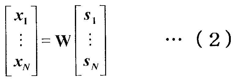
これにより、上記プリコーディングシンボルを各中継局装置が受信した場合、自中継局装置以外への信号による干渉(MUI)はプリコーディングによってキャンセルされて自中継局装置が中継すべき信号のみが受信される。さらに、本実施形態によれば、上記プリコーディングシンボルを各中継局装置が受信した場合、各中継局装置が中継伝送すべき各端末局装置宛の送信データ変調シンボル間も干渉無く個々に分離された状態で受信される。そのため、中継局装置における信号分離処理が不要となり、中継局装置の演算量を削減し、処理遅延を短縮できる。
また、基地局装置では、送信データの最終的な受信者である(中継局装置よりも多数の)各端末局装置との間の伝搬路状態を知る必要がなく、各中継局装置との間の伝搬路状態を知っていれば良い。したがって、基地局装置に通知されるCSIの情報量を削減することができる。さらに、一般的に中継局装置は準静止状態であることが多く、伝搬路の時間変動が緩やかであるため、各中継局装置から通知される中継局CSIの通知頻度を、端末局CSIに比べて大幅に削減できる。
なお、上記プリコーディング部204aは、フィルタ算出部301において線形フィルタとして逆行列を算出して用いているが、これに限られるものではなく、MMSE規範で求めた重み行列W=HH(HHH+αI)-1(Iは単位行列、αは正規化係数を表す)を線形フィルタとして用いても良い。この場合、受信時にMUIは完全にはキャンセルされないが、受信信号対干渉および雑音電力比(Signal to Interference plus Noise power Ratio:SINR)を最大化できるため、受信特性が向上する。
図4は、第1の実施形態に係る中継局装置110aの一構成例を示す機能ブロック図である。なお、この構成例は、図1の無線通信システムの例において、中継局装置110-1および110-2の構成例に当たる。また、以下では、第1から第Mの端末局装置宛の送信データを中継伝送の対象とする場合を例として説明する。
無線受信部402-1から402-Mは、アンテナ部401-1から401-MのM本のアンテナを通じて基地局装置からの信号を受信する。また、無線受信部402-1から402-Mのうちの少なくとも1つは、アンテナ部401-1から401-MのM本のアンテナのうちの少なくとも1本を通じて、第1から第Mの各端末局装置がそれぞれ送信した端末局CSIを含む制御信号を受信する。
端末局CSI取得部419は、第1から第Mの各端末局装置から受信した信号から、第1から第Mの各端末局装置がそれぞれ送信した端末局CSIを取得する。GI除去部403-1から403-Mは、それぞれ各アンテナで受信した基地局装置から送信された信号からGIを取り除く。
FFT部404-1から404-Mは、それぞれのアンテナ毎のGIが除去された受信信号を高速フーリエ変換(Fast Fourier Transform:FFT)などによって時間周波数変換し、サブキャリア毎の受信シンボルに変換する。
CRS分離部405-1から405-Mは、それぞれのアンテナ毎の受信シンボルからCRSを分離し、分離したCRSをそれぞれCRS伝搬路推定部417-1から417-Mに入力し、残りの受信シンボルをそれぞれDMRS分離部406-1から406-Mに入力する。
CRS伝搬路推定部417-1から417-Mは、分離されたアンテナ毎のCRSに基づいて、基地局装置の各アンテナと、中継局装置110aのアンテナ部401-1から401-Mの各アンテナとの間の伝搬路状態をそれぞれ推定する。
中継局CSI生成部418は、CRS伝搬路推定部417-1から417-Mでそれぞれ推定した伝搬路状態に基づいて、それらを基地局装置へ通知するためのCSIを生成する。生成されたCSIは、無線送信部415-1から415-Mのうちの少なくとも1つによって、アンテナ部401-1から401-Mのうちの少なくとも1つのアンテナを通じて基地局装置へ送信される。
DMRS分離部406-1から406-Mは、それぞれのアンテナ毎の受信シンボルからDMRSを分離し、分離したDMRSをそれぞれDMRS伝搬路推定部416-1から416-Mに入力し、残りの受信シンボルをそれぞれ伝搬路補償部407-1から407-Mに入力する。ここで伝搬路補償部407-1から407-Mに入力される受信シンボルは、それぞれ中継伝送先の第1から第Mの各端末局装置宛のシンボルとなる。
DMRS伝搬路推定部416-1から416-Mは、分離されたアンテナ毎のDMRSに基づいて、中継局装置110aのアンテナ部401-1から401-Mの各アンテナにおける基地局装置によるプリコーディング後の伝搬路状態(プリコーディングを伝搬路の一部と見なした仮想的な伝搬路の状態)をそれぞれ推定する。
伝搬路補償部407-1から407-Mは、それぞれDMRS伝搬路推定部416-1から416-Mにおけるプリコーディング後の伝搬路状態の推定結果に基づいて、受信シンボル(各端末局装置宛のシンボル)に対して伝搬路補償(等化)を行なう。
DMRS多重部410-1から410-Mは、各端末局装置において受信信号の伝搬路補償および復調を行なうために参照する既知のシンボルであるDMRSを、伝搬路補償された各端末局装置宛のシンボルにそれぞれ多重する。なお、多重されたDMRSは、プリコーディング部411において各端末局装置宛のシンボルと同様にプリコーディングされる。また、DMRSとの多重は、例えば時分割で多重しても良いし、サブキャリアで分割するような周波数分割で多重しても良い。
プリコーディング部411は、DMRSが多重された第1から第Mの各端末局装置宛のシンボルが入力され、端末局CSI取得部419で取得した各端末局装置のCSIに基づいて、入力された各シンボルに対してプリコーディングを行ない、送信に使用するアンテナ部401-1から401-Mのアンテナ毎のプリコーディングシンボルを生成する。
なお、プリコーディング部411の構成は、基地局装置100におけるプリコーディング部204(図3のプリコーディング部204a)と同様である。ただし、伝搬路状態情報として中継局CSIに代わり端末局CSIを用い、入力として第1から第Mの各端末局装置宛のシンボルが入力される点は異なる。
CRS多重部412-1から412-Mは、各端末局装置において中継局装置110aのアンテナ部401-1から401-Mの各アンテナと各端末局装置の各アンテナとの間の伝搬路状態を推定するために参照する既知のシンボルであるCRSを、各アンテナのプリコーディングシンボルにそれぞれ多重する。
なお、多重されたCRSはプリコーディングが行なわれていない。また、CRSの多重は、各端末局装置の各アンテナにおいて中継局装置110aの各アンテナから送信されたCRSがそれぞれ識別できる形で受信されるように多重されることが好ましい。例えば時分割で多重しても良いし、サブキャリアで分割するような周波数分割で多重しても良い。
IFFT部413-1から413-Mは、CRSが多重されたアンテナ毎のプリコーディングシンボルに対して、それぞれIFFTなどの周波数時間変換を行ない、時間領域の信号へ変換する。GI挿入部414-1から414-Mは、アンテナ毎の時間領域信号にそれぞれGIを挿入する。無線送信部415-1から415-Mは、GIの挿入された信号をアンテナ部401-1から401-Mのそれぞれのアンテナを通じて空間多重伝送により送信する。制御部420は、上記各部を制御し、それぞれの処理を実行させる。
上記の構成によれば、上記のプリコーディングシンボルを各端末局装置が受信した場合、自端末局装置以外への信号による干渉(MUI)はプリコーディングによってキャンセルされて自端末局装置宛の信号のみが受信される。その結果、端末局装置における信号分離処理が不要となり、端末局装置の演算量と処理時間を縮小できる。
また、中継局装置では、中継伝送の対象とする各端末局装置宛の受信シンボルについて復調および誤り訂正復号を行なわずにマルチユーザMIMOのためのプリコーディングを行なうことが可能となり、中継局装置の演算量と処理時間を縮小できる。
図5は、第1の実施形態に係る端末局装置120aの一構成例を示す機能ブロック図である。なお、図1の無線通信システムの例では、端末局装置120-1から120-8の構成例に当たる。
無線受信部502は、アンテナ部501のアンテナを通じて中継局装置からの信号を受信する。GI除去部503は、受信した信号からGIを取り除く。FFT部504は、GIが除去された受信信号をFFTなどによって時間周波数変換し、サブキャリア毎の受信シンボルに変換する。
CRS分離部505は、受信シンボルからCRSを分離し、分離したCRSをCRS伝搬路推定部512に入力し、残りの受信シンボルをDMRS分離部506に入力する。CRS伝搬路推定部512は、分離されたCRSに基づいて、中継局装置の各アンテナと、端末局装置120aのアンテナ部501のアンテナとの間の伝搬路状態を推定する。
端末局CSI生成部513は、CRS伝搬路推定部512で推定した伝搬路状態に基づいて、それを中継局装置へ通知するためのCSIを生成する。無線送信部514は、アンテナ部501のアンテナを通じて、端末局CSI生成部513で生成したCSIを中継局装置へ送信する。
DMRS分離部506は、受信シンボルからDMRSを分離し、分離したDMRSをDMRS伝搬路推定部511に入力し、残りの受信シンボルを伝搬路補償部507に入力する。DMRS伝搬路推定部511は、分離されたDMRSに基づいて、中継局装置によるプリコーディング後の伝搬路状態をそれぞれ推定する。
伝搬路補償部507は、DMRS伝搬路推定部511におけるプリコーディング後の伝搬路状態の推定結果に基づいて、受信シンボル(各端末局装置宛のシンボル)に対して伝搬路補償(等化)を行なう。復調部509は、伝搬路補償された受信シンボルに対して復調を行なう。なお、変調方式が指定されている場合は、その変調方式に基づいて復調を行なう。
復号化部510は、復調された系列に対して誤り訂正復号処理を行ない、受信データ系列を生成し出力する。なお、符号化率が指定されている場合は、その符号化率に従ってレートマッチング(デパンクチャ)を行なってから誤り訂正復号処理を行なう。制御部515は、上記各部を制御し、それぞれの処理を実行させる。
図6は、本実施形態における無線通信システムの基地局装置、中継局装置、端末局装置間の処理手順の一例を示したシーケンス図である。まず、基地局装置100は、CRSを報知信号(ブロードキャスト信号)や送信データに多重するなどして送信する。各中継局装置は、基地局装置100からのCRSを受信すると、CRS信号の受信状態に基づいて基地局装置100の各アンテナと自中継局装置の各アンテナとの間の伝搬路状態を推定し、推定した伝搬路状態を表す中継局CSIを生成して基地局装置100へ通知する。
また、各中継局装置は、CRSを送信データに多重するなどして、中継伝送先の各端末局装置へ送信する。各端末局装置は、それぞれの中継伝送元の中継局装置110-1または110-2からのCRS信号を受信すると、CRS信号の受信状態に基づいてそれぞれの中継伝送元の中継局装置の各アンテナと自端末局装置の各アンテナとの間の伝搬路状態を推定し、推定した伝搬路状態を表す端末局CSIを生成してそれぞれの中継伝送元の中継局装置へ通知する。
基地局装置100は、端末局装置120-1から120-8宛の各送信データに対して誤り訂正符号化および変調を行ない、DMRSを多重し、最新の中継局CSIに基づいて線形プリコーディングを行なう。さらにCRSを多重した送信信号を生成し、各中継局装置に対してマルチユーザMIMO伝送により同時に送信する。
各中継局装置は、受信信号中のCRSを分離抽出し、CRSの受信状態に基づいて基地局装置100の各アンテナと自中継局装置の各アンテナとの間の伝搬路状態を推定し、推定した伝搬路状態を表す中継局CSIを生成して基地局装置100へ通知する。なお、この中継局CSIの通知は、後に続く各端末局装置宛のマルチユーザMIMO伝送の後か、それまでの間に行なっても良い。
次に各中継局装置は、受信信号中のDMRSを分離抽出し、抽出したDMRSの受信状態に基づいて、受信信号中のデータシンボルに伝搬路補償(等化)を行なう。さらに各中継局装置は、伝搬路補償結果にDMRSを多重し、最新の端末局CSIに基づいて線形プリコーディングを行なう。さらにCRSを多重した送信信号を生成し、各端末局装置に対してマルチユーザMIMO伝送により同時に送信する。
各端末局装置は、受信信号中のCRSを分離抽出し、CRSの受信状態に基づいてそれぞれの中継伝送元の中継局装置110-1または110-2の各アンテナと自端末局装置の各アンテナとの間の伝搬路状態を推定し、推定した伝搬路状態を表す端末局CSIを生成してそれぞれの中継伝送元の中継局装置へ通知する。なお、この端末局CSIの通知は、後に続く自局宛データ検出の後か、それまでの間に行なっても良い。
さらに各端末局装置は、受信信号中のDMRSを分離抽出し、抽出したDMRSの受信状態に基づいて受信信号中のデータシンボルに伝搬路補償(等化)を行ない、復調、誤り訂正復号を行なって自局宛のデータを検出する。
以上の説明のように、本実施形態によれば、基地局装置から複数の中継局装置に対して、中継局装置間のMUIおよび各アンテナで受信される各端末局装置宛の信号間のMUIを抑圧するプリコーディングを用いてマルチユーザMIMO伝送を行なう。その結果、中継局装置において伝搬路補償のみを行なった受信したシンボルに各端末局装置間のMUIを抑圧するプリコーディングを行ない、各端末局装置に対してマルチユーザMIMO伝送を行なうことが可能となる。その結果、伝送効率を向上させることができる。
(第2の実施形態)
第2の実施形態では、基地局装置および中継局装置におけるプリコーディングとして、非線形プリコーディングの1つであるTHPを用いる場合の例について説明する。
第2の実施形態では、基地局装置および中継局装置におけるプリコーディングとして、非線形プリコーディングの1つであるTHPを用いる場合の例について説明する。
第2の実施形態における基地局装置の構成は、第1の実施形態における図2の基地局装置100と同様であり、プリコーディング部204における処理が異なる。以下、第1の実施形態と同じ部分についての説明は省略し、プリコーディング部204について説明する。
図7は、第1の実施形態に係るプリコーディング部204の一構成例を示す機能ブロック図である。この一構成例のプリコーディング部をプリコーディング部204bと表す。また、図7の例を用いて、中継局装置からのCSIとして基地局装置100の各アンテナと各中継局装置の各アンテナとの間の複素伝搬路利得が通知され、非線形プリコーディングであるTHPによってプリコーディングシンボルを生成する場合について説明する。
QR分解部(干渉行列算出部)604は、中継局CSI取得部211で取得した各中継局装置から通知された中継局CSIから、基地局装置100の各アンテナと各中継局装置の各アンテナとの間の複素伝搬路利得を要素に持つチャネル行列Hをサブキャリア毎に生成し、そのチャネル行列Hのエルミート共役HHにQR分解を行なう。そして、ユニタリ行列Qと上三角行列Rとに分解し、さらに上三角行列Rのエルミート共役RH(下三角行列となる)を求める。そして、全中継局装置の各アンテナ間のMUIの利得を表す干渉行列B=(diagRH)-1RH-Iを求めて干渉成分算出部603へ出力し、ユニタリ行列Qを線形フィルタ部605へ出力する。なお、diagXは行列Xの対角成分のみの行列であり、Iは単位行列を表す。ここで、干渉行列Bは式(3)の形となる。

第1のモジュロ演算部602-1は、DMRS多重部203-1でDMRSが多重された第1の端末局装置宛の変調シンボルに対して変調方式によって予め定められたモジュロ幅を用いてモジュロ演算を行なう。なお、第1の端末局装置宛の変調シンボルに対してはMUIが存在しないため、干渉成分減算部は省略している。さらにモジュロ演算部602-1も省略可能である。
干渉成分算出部603は、QR分解部604で求めた干渉行列Bに基づいて、第1の端末局装置宛の各サブキャリアの変調シンボルのモジュロ演算結果が第2の端末局装置宛の各サブキャリアの変調シンボルに与える干渉成分を算出する。ここで、干渉行列Bの2行1列目の要素b2,1が、第1の端末局装置宛の変調シンボルが第2の端末局装置宛の変調シンボルへ及ぼす干渉の複素利得を表しており、この要素に第1の端末局装置宛の変調シンボルのモジュロ演算結果を乗じることによって干渉成分を算出できる。
第2の干渉成分減算部601-2は、DMRS多重部203-2でDMRSが多重された第2の端末局装置宛の変調シンボルから、干渉成分算出部603で算出した第2の端末局装置宛の変調シンボルに対する干渉成分をサブキャリア毎に減算する。
第2のモジュロ演算部602-2は、干渉成分が減算された第2の端末局装置宛の変調シンボルに対して、変調方式によって予め定められたモジュロ幅を用いてモジュロ演算を行なう。
干渉成分算出部603は、第1の端末局装置宛の各サブキャリアの変調シンボルのモジュロ演算結果および第2の端末局装置宛の各サブキャリアの変調シンボルのモジュロ演算結果が、第3の端末局装置宛の各サブキャリアの変調シンボルに与える干渉成分を算出する。ここで、干渉行列Bの3行1列目の要素b3,1は第1の端末局装置宛の変調シンボルが第3の端末局装置宛の変調シンボルへ及ぼす干渉の複素利得を表す。また、干渉行列Bの3行2列目の要素b3,2が第2の端末局装置宛の変調シンボルが第3の端末局装置宛の変調シンボルへ及ぼす干渉の複素利得を表す。これらの要素にそれぞれ第1の端末局装置宛の変調シンボルのモジュロ演算結果および第2の端末局装置宛の変調シンボルのモジュロ演算結果を乗じることによって干渉成分を算出できる。
以降、同様にして、第1から第n-1までの端末局装置宛の変調シンボルが第nの端末局装置宛の変調シンボルへ及ぼす干渉の複素利得bn,1、bn,2、・・・、bn,n-1に、それぞれ第1から第n-1までの端末局装置宛の変調シンボルのモジュロ演算結果を乗じることによって第nの端末局装置に対する干渉成分を算出する。
第Nの干渉成分減算部601-Nは、DMRS多重部203-2でDMRSが多重された第Nの端末局装置宛の変調シンボルから、干渉成分算出部603で算出した第Nの端末局装置宛の変調シンボルに対する干渉成分をサブキャリア毎に減算する。
第Nのモジュロ演算部602-Nは、干渉成分が減算された第Nの端末局装置宛の変調シンボルに対して、変調方式によって予め定められたモジュロ幅を用いてモジュロ演算を行なう。
線形フィルタ部605は、第1のモジュロ演算部602-1から第Nのモジュロ演算部602-Nがそれぞれ出力した第1から第Nの端末局装置宛の変調シンボルのモジュロ演算結果が入力されると、これにQR分解部604で算出したユニタリ行列Qを線形フィルタとしてサブキャリア毎に乗算する。そして、アンテナ部209-1から209-Nの各アンテナからそれぞれ送信すべきプリコーディングシンボルを出力する。
これにより、上記プリコーディングシンボルを各中継局装置が受信した場合、自中継局装置以外への信号による干渉(MUI)はTHPによってキャンセルされて自中継局装置が中継すべき信号のみが受信される。さらに、本実施形態によれば、上記プリコーディングシンボルを各中継局装置が受信した場合、各中継局装置が中継伝送すべき各端末局装置宛の送信データ変調シンボル間も干渉無く個々に分離された状態で受信される。その結果、中継局装置における信号分離処理が不要となり、中継局装置の演算量を削減し、処理遅延を短縮できる。さらに、プリコーディングとして非線形プリコーディングであるTHPを用いることで、電力効率良くMUIを抑圧でき、伝送特性が向上する。
なお、本実施の形態では、THPを実現する方法としてチャネル行列のQR分解を用いる方法を例に挙げているが、これに限られるものではなく、V-BLAST(Vertical Bell Laboratories Layered Space Time)の手法を用いてTHPにおける端末局装置の並べ替えを準最適化するような上記非特許文献4に記載されている方法などを用いても良い。
第2の実施形態における中継局装置110bの構成は、第1の実施形態の図3の中継局装置110aに対して、モジュロ演算部408-1から408-Mが追加され、プリコーディング部411の処理が異なり、その他の構成は同じである。以下、第1の実施形態と同じ部分についての説明は省略し、異なる部分について説明する。
図8は、第2の実施形態に係る中継局装置110bの一構成例を示す機能ブロック図である。モジュロ演算部408-1から408-Mは、それぞれ伝搬路補償部407-1から407-Mが出力する伝搬路補償された各端末局装置宛のシンボルに対して、変調方式によって予め定められたモジュロ幅を用いてモジュロ演算を行なう。
DMRS多重部410-1から410-Mは、DMRSを、モジュロ演算が行なわれた各端末局装置宛のシンボルにそれぞれ多重する。なお、DMRSは、各端末局装置において受信信号の伝搬路補償および復調を行なうために参照する既知のシンボルである。多重されたDMRSは、プリコーディング部411において各端末局装置宛のシンボルと同様にプリコーディングされる。また、DMRSとの多重は、例えば時分割で多重しても良いし、サブキャリアで分割するような周波数分割で多重しても良い。
プリコーディング部411の構成は、基地局装置100におけるプリコーディング部204b(図7のプリコーディング部204b)と同様である。ただし、伝搬路状態情報として中継局CSIに代わり端末局CSIを用い、入力として第1から第Mの各端末局装置宛のシンボルが入力される点が異なる。
上記構成によれば、上記プリコーディングシンボルを各端末局装置が受信した場合、自端末局装置以外への信号による干渉(MUI)はプリコーディングによってキャンセルされて自端末局装置宛の信号のみが受信される。その結果、端末局装置における信号分離処理が不要となり、端末局装置の演算量と処理時間を縮小できる。
また、中継局装置では、中継伝送の対象とする各端末局装置宛の受信シンボルについて復調および誤り訂正復号を行なわずにマルチユーザMIMOのためのプリコーディングを行なうことが可能となり、中継局装置の演算量と処理時間を縮小できる。さらにプリコーディングとして非線形プリコーディングであるTHPを用いることで、電力効率良くMUIを抑圧でき、伝送特性が向上する。
第2の実施形態における端末局装置120bの構成は、第1の実施形態の図5の端末局装置120aと、モジュロ演算部508が加わっているところが異なるが、その他の構成は第1の実施形態と同じである。以下、第1の実施形態と同じ部分についての説明は省略し、異なる部分について説明する。
図9は、第2の実施形態に係る端末局装置120bの一構成例を示す機能ブロック図である。モジュロ演算部508は、伝搬路補償部507が出力する伝搬路補償された受信シンボルに対して、変調方式によって予め定められたモジュロ幅を用いてモジュロ演算を行なう。復調部509は、モジュロ演算が行なわれたシンボルに対して復調を行なう。
図10は、本実施形態における無線通信システムの基地局装置、中継局装置、端末局装置間の処理手順の一例を示したシーケンス図である。まず、基地局装置100は、CRSを報知信号(ブロードキャスト信号)や送信データに多重するなどして送信する。
各中継局装置は、基地局装置100からのCRSを受信すると、CRS信号の受信状態に基づいて基地局装置100の各アンテナと自中継局装置の各アンテナとの間の伝搬路状態を推定する。そして、推定した伝搬路状態を表す中継局CSIを生成して基地局装置100へ通知する。
また、各中継局装置は、CRSを送信データに多重するなどして、中継伝送先の各端末局装置へ送信する。各端末局装置は、それぞれの中継伝送元の中継局装置110-1または110-2からのCRS信号を受信すると、CRS信号の受信状態に基づいてそれぞれの中継伝送元の中継局装置の各アンテナと自端末局装置の各アンテナとの間の伝搬路状態を推定する。そして、推定した伝搬路状態を表す端末局CSIを生成してそれぞれの中継伝送元の中継局装置へ通知する。
基地局装置100は、端末局装置120-1から120-8宛の各送信データに対して誤り訂正符号化および変調を行ない、DMRSを多重し、最新の中継局CSIに基づいてTHPによる非線形プリコーディングを行なう。さらにCRSを多重した送信信号を生成し、各中継局装置に対してマルチユーザMIMO伝送により同時に送信する。
各中継局装置は、受信信号中のCRSを分離抽出し、CRSの受信状態に基づいて基地局装置100の各アンテナと自中継局装置の各アンテナとの間の伝搬路状態を推定し、推定した伝搬路状態を表す中継局CSIを生成して基地局装置100へ通知する。なお、この中継局CSIの通知は、後に続く各端末局装置宛のマルチユーザMIMO伝送の後か、それまでの間に行なっても良い。
次に各中継局装置は、受信信号中のDMRSを分離抽出し、抽出したDMRSの受信状態に基づいて、受信信号中のデータシンボルに伝搬路補償(等化)を行なう。さらに各中継局装置は、伝搬路補償結果にモジュロ演算を行なう。
さらに各中継局装置は、モジュロ演算結果の受信シンボルにDMRSを多重し、最新の端末局CSIに基づいてTHPによる非線形プリコーディングを行なう。さらにCRSを多重した送信信号を生成し、各端末局装置に対してマルチユーザMIMO伝送により同時に送信する。
各端末局装置は、受信信号中のCRSを分離抽出し、CRSの受信状態に基づいてそれぞれの中継伝送元の中継局装置110-1または110-2の各アンテナと自端末局装置の各アンテナとの間の伝搬路状態を推定する。そして、推定した伝搬路状態を表す端末局CSIを生成してそれぞれの中継伝送元の中継局装置へ通知する。なお、この端末局CSIの通知は、後に続く自局宛データ検出の後か、それまでの間に行なっても良い。
さらに各端末局装置は、受信信号中のDMRSを分離抽出し、抽出したDMRSの受信状態に基づいて受信信号中のデータシンボルに伝搬路補償(等化)を行なう。そして、さらにモジュロ演算を行なってから、復調、誤り訂正復号を行ない自局宛のデータを検出する。
以上の説明のように、本実施形態によれば、基地局装置から複数の中継局装置に対して、中継局装置間のMUIおよび各アンテナで受信される各端末局装置宛の信号間のMUIを抑圧するプリコーディングを用いてマルチユーザMIMO伝送を行なう。そして、中継局装置において伝搬路補償のみを行なった受信したシンボルに各端末局装置間のMUIを抑圧するプリコーディングを行ない、各端末局装置に対してマルチユーザMIMO伝送を行なう。その結果、伝送効率を向上させることができる。さらに、上記プリコーディングとして非線形プリコーディングであるTHPを用いることにより、電力効率良くMUIを抑圧でき、さらに伝送特性が向上する。
(第3の実施形態)
第3の実施形態では、中継局装置において、各端末局装置宛の伝搬路補償されたシンボルに対して受信信号点の仮判定を行なったのちにプリコーディングを行なう場合の例について説明する。また、第2の実施形態と同様、プリコーディングとして非線形プリコーディングの1つであるTHPを用いる場合の例について説明する。
第3の実施形態では、中継局装置において、各端末局装置宛の伝搬路補償されたシンボルに対して受信信号点の仮判定を行なったのちにプリコーディングを行なう場合の例について説明する。また、第2の実施形態と同様、プリコーディングとして非線形プリコーディングの1つであるTHPを用いる場合の例について説明する。
第3の実施形態における基地局装置および端末局装置の構成は、第2の実施形態と同じであるので説明を省略する。第3の実施形態における中継局装置110cの構成は、第2の実施形態における図8の中継局装置110bに対して、仮判定部409-1から409-Mが追加され、その他の構成は同じである。以下、第2の実施形態と同じ部分についての説明は省略し、異なる部分について説明する。
図11は、第3の実施形態における中継局装置110cの一構成例を示す機能ブロック図である。仮判定部409-1から409-Mは、それぞれモジュロ演算が行なわれた各端末局装置宛のシンボルに対して、その信号点(受信信号点)と、変調方式で定まる信号点(変調信号点)との位置関係に基づいて送信信号点の推定を行なう。そして、推定した信号点(仮判定信号点)で新たに各端末局装置宛のシンボルを生成する。
図12は、仮判定部409-1から409-Mにおける仮判定の一例を示す概念図である。図12では、横軸に信号の同相(In-phase)成分のI軸を、縦軸に直交(Quadrature)成分のQ軸を取り、変調方式として16値直交振幅変調(16 Quadrature Amplitude Modulation:16QAM)を用いた場合の信号点配置(コンスタレーション)の例を示している。白丸および白四角が変調信号点の位置を表しており、雑音が加わっている受信信号点が図中の黒丸の位置であったとすると、仮判定部409-1から409-Mは白四角の変調信号点を仮判定信号点として出力する。
DMRS多重部410-1から410-Mは、各端末局装置において受信信号の伝搬路補償および復調を行なうために参照する既知のシンボルであるDMRSを、仮判定部409-1から409-Mにおいて生成された各端末局装置宛のシンボルにそれぞれ多重する。なお、多重されたDMRSは、プリコーディング部411において各端末局装置宛のシンボルと同様にプリコーディングされる。また、DMRSとの多重は、例えば時分割で多重しても良いし、サブキャリアで分割するような周波数分割で多重しても良い。
上記構成によれば、中継局装置では、中継伝送の対象とする各端末局装置宛の受信シンボルについて誤り訂正復号は行なわず、より演算量の小さい、受信信号点の仮判定を行なった上でマルチユーザMIMOのためのプリコーディングを行なうことが可能となり、中継局装置の演算量と処理時間を縮小できる。
図13は、本実施形態における無線通信システムの基地局装置、中継局装置、端末局装置間の処理手順の一例を示したシーケンス図である。まず、基地局装置100は、CRSを報知信号(ブロードキャスト信号)や送信データに多重するなどして送信する。
各中継局装置は、基地局装置100からのCRSを受信すると、CRS信号の受信状態に基づいて基地局装置100の各アンテナと自中継局装置の各アンテナとの間の伝搬路状態を推定し、推定した伝搬路状態を表す中継局CSIを生成して基地局装置100へ通知する。また、各中継局装置は、CRSを送信データに多重するなどして、中継伝送先の各端末局装置へ送信する。
各端末局装置は、それぞれの中継伝送元の中継局装置110-1または110-2からのCRS信号を受信すると、CRS信号の受信状態に基づいてそれぞれの中継伝送元の中継局装置の各アンテナと自端末局装置の各アンテナとの間の伝搬路状態を推定し、推定した伝搬路状態を表す端末局CSIを生成してそれぞれの中継伝送元の中継局装置へ通知する。
基地局装置100は、端末局装置120-1から120-8宛の各送信データに対して誤り訂正符号化および変調を行ない、DMRSを多重し、最新の中継局CSIに基づいてTHPによる非線形プリコーディングを行なう。さらにCRSを多重した送信信号を生成し、各中継局装置に対してマルチユーザMIMO伝送により同時に送信する。
各中継局装置は、受信信号中のCRSを分離抽出し、CRSの受信状態に基づいて基地局装置100の各アンテナと自中継局装置の各アンテナとの間の伝搬路状態を推定し、推定した伝搬路状態を表す中継局CSIを生成して基地局装置100へ通知する。なお、この中継局CSIの通知は、後に続く各端末局装置宛のマルチユーザMIMO伝送の後か、それまでの間に行なっても良い。
次に各中継局装置は、受信信号中のDMRSを分離抽出し、抽出したDMRSの受信状態に基づいて、受信信号中のデータシンボルに伝搬路補償(等化)を行なう。さらに各中継局装置は、伝搬路補償結果にモジュロ演算を行なう。さらに各中継局装置は、モジュロ演算結果の受信シンボルに対して仮判定を行ない、データシンボルを再生成する。
各中継局装置は、仮判定結果のシンボルにDMRSを多重し、最新の端末局CSIに基づいてTHPによる非線形プリコーディングを行なう。さらにCRSを多重した送信信号を生成し、各端末局装置に対してマルチユーザMIMO伝送により同時に送信する。
各端末局装置は、受信信号中のCRSを分離抽出し、CRSの受信状態に基づいてそれぞれの中継伝送元の中継局装置110-1または110-2の各アンテナと自端末局装置の各アンテナとの間の伝搬路状態を推定し、推定した伝搬路状態を表す端末局CSIを生成してそれぞれの中継伝送元の中継局装置へ通知する。なお、この端末局CSIの通知は、後に続く自局宛データ検出の後か、それまでの間に行なっても良い。
さらに各端末局装置は、受信信号中のDMRSを分離抽出し、抽出したDMRSの受信状態に基づいて受信信号中のデータシンボルに伝搬路補償(等化)を行ない、さらにモジュロ演算を行なってから、復調、誤り訂正復号を行なって自局宛のデータを検出する。
以上の説明のように、本実施形態によれば、基地局装置から複数の中継局装置に対して、中継局装置間のMUIおよび各アンテナで受信される各端末局装置宛の信号間のMUIを抑圧するプリコーディングを用いてマルチユーザMIMO伝送を行ない、中継局装置において伝搬路補償と受信信号点の仮判定のみを行なった受信したシンボルに各端末局装置間のMUIを抑圧するプリコーディングを行なって各端末局装置に対してマルチユーザMIMO伝送を行なうことが可能となり、伝送効率を向上させることができる。
さらに、上記プリコーディングとして非線形プリコーディングであるTHPを用いることにより、MUIの抑圧を電力効率良く行なうことが可能となり、さらに伝送特性が向上する。また、中継局装置において仮判定を行なうため、各端末局装置における受信誤り率を低減できる。
(第4の実施形態)
上記各実施形態では、図1に示すような、基地局装置100が複数の端末局装置(例えば、第1から第8までの端末局装置120-1から120-8)と通信する下りリンクの伝送において、複数の中継局装置(例えば、第1の中継局装置110-1および第2の中継局装置110-2)を1回経由して、各端末局装置宛の送信データを空間的に多重して同時通信するマルチユーザMIMO伝送を行なう無線通信システムについて説明している。
上記各実施形態では、図1に示すような、基地局装置100が複数の端末局装置(例えば、第1から第8までの端末局装置120-1から120-8)と通信する下りリンクの伝送において、複数の中継局装置(例えば、第1の中継局装置110-1および第2の中継局装置110-2)を1回経由して、各端末局装置宛の送信データを空間的に多重して同時通信するマルチユーザMIMO伝送を行なう無線通信システムについて説明している。
第4の実施形態では、2回以上、階層的に中継局装置を経由して、各端末局装置宛の送信データを空間的に多重して同時通信するマルチユーザMIMO伝送を行なう無線通信システムについて説明する。
図14は、第4の実施形態に係る無線通信システムの概略構成例を示す図である。図14の例では、第1の端末局装置120-1および第2の端末局装置120-2宛の送信データは、第5の中継局装置110-5を経由する。第3の端末局装置120-3および第4の端末局装置120-4宛の送信データは第6の中継局装置110-6を経由する。第5の端末局装置120-5および第6の端末局装置120-6宛の送信データは第7の中継局装置110-7を経由する。第7の端末局装置120-7および第8の端末局装置120-8宛の送信データは第8の中継局装置110-8を経由する。このようにして、送信データが伝送される。
さらに、第5の中継局装置110-5および第6の中継局装置110-6を経由する送信データは、第3の中継局装置110-3を経由して伝送される。また、第7の中継局装置110-7および第8の中継局装置110-8を経由する送信データは、第4の中継局装置110-4を経由して伝送される。
第4の実施形態における基地局装置100、および端末局装置120-1から120-8は、上記各実施形態におけるいずれかの構成によって実現できる。また、中継局装置110-3と110-4の構成は、上記各実施形態における中継局装置と同様である。ただし、端末局CSIに代わって中継伝送先の次段の各中継局装置との間の伝搬路状態を表した中継局CSIが次段の各中継局装置から通知され、それに基づいてプリコーディングを行なう点は異なる。
さらに、中継局装置110-5から110-8の構成も、上記各実施形態における中継局装置と同様である。ただし、アンテナ数が異なり、中継局CSIとして中継伝送元の前段の中継局装置との間の伝搬路状態を表すCSIを前段の中継局装置に通知する点は異なる。
なお、図14の例では、中継伝送の階層を表したツリー構造において、各ブランチが同じ階層数であり、同数の中継局装置および端末局装置が含まれるが、実施形態はこれに限られるものではなく、各ブランチで階層数が異なっていても良いし、含まれる中継局装置や端末局装置の数が異なっていても良い。
本実施形態によれば、基地局装置からの送信信号を異なる中継局装置によって複数回(複数階層)にわたって中継伝送される複数の端末局装置に対して、各階層において空間多重を用いて同時に伝送することが可能となり、伝送効率を向上させることができる。
なお、上記各実施形態では、必ず中継局装置によって基地局装置からの伝送が端末局装置に中継されているが、これに限られるものではなく、一部の端末局装置は基地局装置と直接通信を行なう形態であっても良い。この場合、基地局装置が当該端末局装置の端末局CSIを受信し、中継局CSIと当該端末局CSIとに基づいて中継局装置と当該端末局装置とに対する送信信号をマルチユーザMIMOで同時に伝送する。
また、上記各実施形態では、基地局装置から中継局装置、中継局装置から中継局装置、および中継局装置から端末局装置、それぞれの伝送において同一のプリコーディング方式を用いたマルチユーザMIMO伝送を行なっているが、これに限られるものではない。例えば、基地局装置から中継局装置および中継局装置から中継局装置におけるマルチユーザMIMO伝送ではTHPなどの非線形プリコーディングを用い、中継局装置から端末局装置におけるマルチユーザMIMO伝送では線形プリコーディングを用いても良い。
また、基地局装置から中継局装置および中継局装置から中継局装置におけるマルチユーザMIMO伝送では詳細なCSIに基づいた線形プリコーディングを用い、中継局装置から端末局装置におけるマルチユーザMIMO伝送ではPMIに基づいたビームフォーミングを用いるなど、それぞれ異なるプリコーディング方式を用いても良い。
本発明による通信装置で動作するプログラムは、本発明に関わる上記実施形態の機能を実現するように、CPU(Central Processing Unit)等を制御するプログラム(コンピュータを機能させるプログラム)であっても良い。そして、これら装置で取り扱われる情報は、その処理時に一時的にRAM(Random Access Memory)に蓄積され、その後、Flash ROM(Read Only Memory)などの各種ROMやHDD(Hard Disk Drive)に格納され、必要に応じてCPUによって読み出し、修正・書き込みが行なわれる。
また、図3、図7等の各構成の機能を実現するためのプログラムをコンピュータ読み取り可能な記録媒体に記録して、この記録媒体に記録されたプログラムをコンピュータシステムに読み込ませ、実行することにより各部の処理を行なってもよい。なお、ここでいう「コンピュータシステム」とは、OSや周辺機器等のハードウェアを含むものとする。
また、「コンピュータ読み取り可能な記録媒体」とは、フレキシブルディスク、光磁気ディスク、ROM、CD-ROM等の可搬媒体、コンピュータシステムに内蔵されるハードディスク等の記憶装置のことをいう。さらに「コンピュータ読み取り可能な記録媒体」とは、インターネット等のネットワークや電話回線等の通信回線を介してプログラムを送信する場合の通信線のように、短時間の間、動的にプログラムを保持するもの、その場合のサーバやクライアントとなるコンピュータシステム内部の揮発性メモリのように、一定時間プログラムを保持しているものも含むものとする。また上記プログラムは、前述した機能の一部を実現するためのものであっても良く、さらに前述した機能をコンピュータシステムにすでに記録されているプログラムとの組み合わせで実現できるものであっても良い。
また、上述した実施形態における通信装置(基地局装置、中継局装置および端末局装置)の一部、または全部を典型的には集積回路であるLSIとして実現してもよい。通信装置の各機能ブロックは個別にチップ化してもよいし、一部、または全部を集積してチップ化してもよい。また、集積回路化の手法はLSIに限らず専用回路、または汎用プロセッサで実現しても良い。また、半導体技術の進歩によりLSIに代替する集積回路化の技術が出現した場合、当該技術による集積回路を用いることも可能である。
以上、この発明の実施形態を、図面を参照して詳述しているが、具体的な構成はこれらの実施形態に限られるものではなく、この発明の要旨を逸脱しない範囲の設計変更等された発明も含まれる。
100 基地局装置(無線送信装置)
110、110-1~K、110a~c 中継局装置
120、120-1~M、120a~b 端末局装置(無線受信装置)
201-1~N 符号化部
202-1~N 変調部
203-1~N DMRS多重部
204、204a~b プリコーディング部
205-1~N CRS多重部
206-1~N IFFT部
207-1~N GI挿入部
208-1~N 無線送信部
209-1~N アンテナ部
210 無線受信部
211 中継局CSI取得部
212 制御部
301 フィルタ算出部
302 線形フィルタ部
401-1~M アンテナ部
402-1~M 無線受信部
403-1~M GI除去部
404-1~M FFT部
405-1~M CRS分離部
406-1~M DMRS分離部
407-1~M 伝搬路補償部
408-1~M モジュロ演算部
409-1~M 仮判定部
410-1~M DMRS多重部
411 プリコーディング部
412-1~M CRS多重部
413-1~M IFFT部
414-1~M GI挿入部
415-1~M 無線送信部
416-1~M DMRS伝搬路推定部
417-1~M CRS伝搬路推定部
418 中継局CSI生成部
419 端末局CSI取得部
420 制御部
501 アンテナ部
502 無線受信部
503 GI除去部
504 FFT部
505 CRS分離部
506 DMRS分離部
507 伝搬路補償部
508 モジュロ演算部
509 復調部
510 復号化部
511 DMRS伝搬路推定部
512 CRS伝搬路推定部
513 端末局CSI生成部
514 無線送信部
515 制御部
601-2~N 干渉成分減算部
602-1~N 第1~Nのモジュロ演算部
603 干渉成分算出部
604 QR分解部
605 線形フィルタ部
110、110-1~K、110a~c 中継局装置
120、120-1~M、120a~b 端末局装置(無線受信装置)
201-1~N 符号化部
202-1~N 変調部
203-1~N DMRS多重部
204、204a~b プリコーディング部
205-1~N CRS多重部
206-1~N IFFT部
207-1~N GI挿入部
208-1~N 無線送信部
209-1~N アンテナ部
210 無線受信部
211 中継局CSI取得部
212 制御部
301 フィルタ算出部
302 線形フィルタ部
401-1~M アンテナ部
402-1~M 無線受信部
403-1~M GI除去部
404-1~M FFT部
405-1~M CRS分離部
406-1~M DMRS分離部
407-1~M 伝搬路補償部
408-1~M モジュロ演算部
409-1~M 仮判定部
410-1~M DMRS多重部
411 プリコーディング部
412-1~M CRS多重部
413-1~M IFFT部
414-1~M GI挿入部
415-1~M 無線送信部
416-1~M DMRS伝搬路推定部
417-1~M CRS伝搬路推定部
418 中継局CSI生成部
419 端末局CSI取得部
420 制御部
501 アンテナ部
502 無線受信部
503 GI除去部
504 FFT部
505 CRS分離部
506 DMRS分離部
507 伝搬路補償部
508 モジュロ演算部
509 復調部
510 復号化部
511 DMRS伝搬路推定部
512 CRS伝搬路推定部
513 端末局CSI生成部
514 無線送信部
515 制御部
601-2~N 干渉成分減算部
602-1~N 第1~Nのモジュロ演算部
603 干渉成分算出部
604 QR分解部
605 線形フィルタ部
Claims (10)
- マルチユーザMIMO伝送により複数のデータ系列を中継する無線中継装置であって、
推定された自無線中継装置と中継元との間の伝搬路状態を示す第1のCSIを生成する第1のCSI生成部と、
前記第1のCSIを前記中継元へ送信する無線送信部と、
推定された自無線中継装置と複数の中継先のそれぞれとの間の伝搬路状態を示す第2のCSIを取得する第2のCSI取得部と、
前記第1のCSIに基づいてプリコーディングがなされ、前記中継元から同時に複数の無線中継装置に送信されたデータ系列のうち、受信されたデータ系列に対して、伝搬路補償後に、前記取得された第2のCSIに基づいてプリコーディングを行なうプリコーディング部と、を備え、
前記プリコーディングが行なわれたデータ系列を前記複数の中継先へ同時に送信することを特徴とする無線中継装置。 - 前記プリコーディング部は、前記中継元から送信されたデータ系列に対して、非線形プリコーディングを行なうことを特徴とする請求項1記載の無線中継装置。
- 前記プリコーディング部は、前記中継元から送信されたデータ系列に対して、受信信号点の仮判定を行った後にプリコーディングを行なうことを特徴とする請求項1記載の無線中継装置。
- マルチユーザMIMO伝送により複数のデータ系列を送信する無線送信装置であって、
推定された自無線送信装置と複数の無線中継装置のそれぞれとの間の伝搬路状態を示す中継局CSIを取得する中継局CSI取得部と、
前記取得された中継局CSIに基づいて、複数のデータ系列に対してプリコーディングを行なうプリコーディング部と、を備え、
前記プリコーディングが行なわれたデータ系列を前記複数の無線中継装置へ同時に送信することを特徴とする無線送信装置。 - 前記プリコーディング部は、前記複数のデータ系列に対して非線形プリコーディングを行なうことを特徴とする請求項4記載の無線送信装置。
- 請求項1記載の無線中継装置を介して、マルチユーザMIMO伝送がなされたデータ系列を受信する無線受信装置であって、
前記第2のCSIを生成する第2のCSI生成部と、
前記第2のCSIを前記無線中継装置へ送信する無線送信部と、を備え、
前記無線中継装置で前記第2のCSIに基づいてプリコーディングが行なわれ、同時に複数の無線受信装置へ送信されたデータ系列を受信することを特徴とする無線受信装置。 - 中継によりマルチユーザMIMO伝送を行なう無線通信システムであって、
推定された自無線送信装置と複数の無線中継装置のそれぞれとの間の伝搬路状態を示す中継局CSIに基づいて、複数のデータ系列に対してプリコーディングを行ない、前記プリコーディングが行なわれたデータ系列を前記複数の無線中継装置へ同時に送信する無線送信装置と、
推定された自無線中継装置と中継元との間の伝搬路状態を示す第1のCSIを生成して前記中継元へ送信し、前記無線送信装置から送信されたデータ系列に由来し、前記第1のCSIに基づいてプリコーディングがなされ、前記中継元から同時に複数の無線中継装置に送信されたデータ系列のうち、受信されたデータ系列に対して、推定された自無線中継装置と複数の中継先のそれぞれとの間の伝搬路状態を示す伝搬路状態を示す第2のCSIに基づいてプリコーディングを行ない、前記受信され、プリコーディングが行なわれたデータ系列を前記複数の中継先へ同時に送信する無線中継装置と、
前記第2のCSIを生成して、受信されるデータ系列の送信元へ送信し、前記無線中継装置で中継されたデータ系列に由来し、前記受信されるデータ系列の送信元で前記第2のCSIに基づいてプリコーディングが行なわれ、同時に複数の無線受信装置へ送信されたデータ系列を受信する無線受信装置と、を備えることを特徴とする無線通信システム。 - 前記無線送信装置から前記無線受信装置まで複数階層の無線中継装置を経由してマルチユーザMIMO伝送を行なうことを特徴とする請求項7記載の無線通信システム。
- マルチユーザMIMO伝送により複数のデータ系列の中継を制御する制御プログラムであって、
推定された、制御される無線中継装置と中継元との間の伝搬路状態を示す第1のCSIを生成する処理と、
前記第1のCSIを前記中継元へ送信する処理と、
推定された前記制御される無線中継装置と複数の中継先のそれぞれとの間の伝搬路状態を示す第2のCSIを取得する処理と、
前記第1のCSIに基づいてプリコーディングがなされ、前記中継元から同時に複数の無線中継装置に送信されたデータ系列のうち、受信されたデータ系列に対して、伝搬路補償後に、前記取得された第2のCSIに基づいてプリコーディングを行なう処理と、
前記プリコーディングが行なわれたデータ系列を前記複数の中継先へ同時に送信する処理と、を含む一連の処理を、前記制御される無線中継装置に実行させることを特徴とする制御プログラム。 - マルチユーザMIMO伝送により複数のデータ系列の中継を制御する集積回路であって、
推定された、制御される無線中継装置と中継元との間の伝搬路状態を示す第1のCSIを生成する機能と、
前記第1のCSIを前記中継元へ送信する機能と、
推定された前記制御される無線中継装置と複数の中継先のそれぞれとの間の伝搬路状態を示す第2のCSIを取得する機能と、
前記第1のCSIに基づいてプリコーディングがなされ、前記中継元から同時に複数の無線中継装置に送信されたデータ系列のうち、受信されたデータ系列に対して、伝搬路補償後に、前記取得された第2のCSIに基づいてプリコーディングを行なう機能と、
前記プリコーディングが行なわれたデータ系列を前記複数の中継先へ同時に送信する機能と、を含む一連の機能を、前記制御される無線中継装置に発揮させることを特徴とする集積回路。
Applications Claiming Priority (2)
| Application Number | Priority Date | Filing Date | Title |
|---|---|---|---|
| JP2011-130721 | 2011-06-10 | ||
| JP2011130721A JP2013004997A (ja) | 2011-06-10 | 2011-06-10 | 無線中継装置、無線送信装置、無線受信装置、無線通信システム、制御プログラムおよび集積回路 |
Publications (1)
| Publication Number | Publication Date |
|---|---|
| WO2012169428A1 true WO2012169428A1 (ja) | 2012-12-13 |
Family
ID=47295994
Family Applications (1)
| Application Number | Title | Priority Date | Filing Date |
|---|---|---|---|
| PCT/JP2012/064141 Ceased WO2012169428A1 (ja) | 2011-06-10 | 2012-05-31 | 無線中継装置、無線送信装置、無線受信装置、無線通信システム、制御プログラムおよび集積回路 |
Country Status (2)
| Country | Link |
|---|---|
| JP (1) | JP2013004997A (ja) |
| WO (1) | WO2012169428A1 (ja) |
Families Citing this family (2)
| Publication number | Priority date | Publication date | Assignee | Title |
|---|---|---|---|---|
| JP6970409B2 (ja) * | 2018-01-10 | 2021-11-24 | 日本電信電話株式会社 | 中継装置および中継方法 |
| CN119137881A (zh) * | 2022-04-25 | 2024-12-13 | 松下电器(美国)知识产权公司 | 通信装置及通信方法 |
Citations (4)
| Publication number | Priority date | Publication date | Assignee | Title |
|---|---|---|---|---|
| JP2006148867A (ja) * | 2004-08-31 | 2006-06-08 | Ntt Docomo Inc | 通信システム、通信ノード及び通信方法 |
| JP2009517918A (ja) * | 2005-11-29 | 2009-04-30 | テレフオンアクチーボラゲット エル エム エリクソン(パブル) | 無線マルチホップ中継ネットワークにおけるスケジューリング |
| JP2010050643A (ja) * | 2008-08-20 | 2010-03-04 | Nagoya Institute Of Technology | 受信装置及び受信方法 |
| JP2011077565A (ja) * | 2009-09-29 | 2011-04-14 | Hitachi Ltd | 無線中継システム、中継装置、及び中継方法 |
Family Cites Families (1)
| Publication number | Priority date | Publication date | Assignee | Title |
|---|---|---|---|---|
| JP5319443B2 (ja) * | 2009-08-05 | 2013-10-16 | シャープ株式会社 | 基地局装置、端末装置および無線通信システム |
-
2011
- 2011-06-10 JP JP2011130721A patent/JP2013004997A/ja active Pending
-
2012
- 2012-05-31 WO PCT/JP2012/064141 patent/WO2012169428A1/ja not_active Ceased
Patent Citations (4)
| Publication number | Priority date | Publication date | Assignee | Title |
|---|---|---|---|---|
| JP2006148867A (ja) * | 2004-08-31 | 2006-06-08 | Ntt Docomo Inc | 通信システム、通信ノード及び通信方法 |
| JP2009517918A (ja) * | 2005-11-29 | 2009-04-30 | テレフオンアクチーボラゲット エル エム エリクソン(パブル) | 無線マルチホップ中継ネットワークにおけるスケジューリング |
| JP2010050643A (ja) * | 2008-08-20 | 2010-03-04 | Nagoya Institute Of Technology | 受信装置及び受信方法 |
| JP2011077565A (ja) * | 2009-09-29 | 2011-04-14 | Hitachi Ltd | 無線中継システム、中継装置、及び中継方法 |
Non-Patent Citations (1)
| Title |
|---|
| DONGMEI JIANG ET AL.: "Linear precoding with limited feedback in multiuser MIMO relay networks", COMMUNICATIONS AND INFORMATION TECHNOLOGY, 2009. ISCIT 2009. 9TH INTERNATIONAL SYMPOSIUM ON, 28 September 2009 (2009-09-28), pages 337 - 342 * |
Also Published As
| Publication number | Publication date |
|---|---|
| JP2013004997A (ja) | 2013-01-07 |
Similar Documents
| Publication | Publication Date | Title |
|---|---|---|
| US9281880B2 (en) | Wireless transmission device and wireless reception device | |
| JP5275835B2 (ja) | 基地局装置、端末装置および無線通信システム | |
| JP5149257B2 (ja) | 無線通信システム、通信装置および無線通信方法 | |
| KR101066151B1 (ko) | Mimo 무선 통신 시스템에서 효율적인 프리코딩 피드백을 제공하기 위한 방법 및 장치 | |
| WO2012060237A1 (ja) | 無線送信装置、無線受信装置、無線通信システム、制御プログラムおよび集積回路 | |
| WO2008150148A2 (en) | Cdd precoding for open loop su mimo | |
| WO2013131391A1 (zh) | 一种多用户干扰抑制方法、终端及基站 | |
| JP2013118567A (ja) | 無線基地局装置、無線通信システム及び無線通信方法 | |
| JP5859913B2 (ja) | 無線受信装置、無線送信装置、無線通信システム、プログラムおよび集積回路 | |
| JP5641787B2 (ja) | 端末装置及びそれを用いた無線通信システム | |
| KR20110079755A (ko) | 멀티 유저 mimo 시스템, 수신 장치 및 송신 장치 | |
| JP5909060B2 (ja) | 無線送信装置、無線受信装置、プログラム、集積回路および無線通信システム | |
| WO2012169428A1 (ja) | 無線中継装置、無線送信装置、無線受信装置、無線通信システム、制御プログラムおよび集積回路 | |
| JP5859786B2 (ja) | 無線送信装置、無線受信装置、無線通信システム、プログラムおよび集積回路 | |
| JP5543265B2 (ja) | 基地局装置、端末装置および無線通信システム | |
| JP2011142513A (ja) | 無線通信システム、送信装置、受信装置、通信方法および集積回路 | |
| JP2013123196A (ja) | プリコーディング装置、無線送信装置、プリコーディング方法、プログラムおよび集積回路 | |
| JP6047743B2 (ja) | 無線通信システム、無線通信装置および無線通信方法 | |
| JP6083598B2 (ja) | 無線通信システム、無線通信装置および無線通信方法 | |
| WO2011129261A1 (ja) | 基地局装置、無線通信システム、基地局装置の送信方法、及び送信プログラム | |
| JP2012015963A (ja) | 端末装置、基地局装置及びそれらを用いた無線通信システム | |
| JP2013126144A (ja) | 送信装置、受信装置および通信システム | |
| JP2013506319A (ja) | 無線信号の受信方法、送信方法、受信ノード装置及び無線通信システム | |
| WO2013038906A1 (ja) | 無線送信装置、無線受信装置、および無線通信システム | |
| Ahmed et al. | Dynamic selection for CoMP-JT over correlated MIMO channel with open loop precoding and IRC receiver for LTE-A |
Legal Events
| Date | Code | Title | Description |
|---|---|---|---|
| 121 | Ep: the epo has been informed by wipo that ep was designated in this application |
Ref document number: 12796482 Country of ref document: EP Kind code of ref document: A1 |
|
| NENP | Non-entry into the national phase |
Ref country code: DE |
|
| 122 | Ep: pct application non-entry in european phase |
Ref document number: 12796482 Country of ref document: EP Kind code of ref document: A1 |