WO2012169386A1 - シート部材の搬送方法及び搬送装置 - Google Patents
シート部材の搬送方法及び搬送装置 Download PDFInfo
- Publication number
- WO2012169386A1 WO2012169386A1 PCT/JP2012/063700 JP2012063700W WO2012169386A1 WO 2012169386 A1 WO2012169386 A1 WO 2012169386A1 JP 2012063700 W JP2012063700 W JP 2012063700W WO 2012169386 A1 WO2012169386 A1 WO 2012169386A1
- Authority
- WO
- WIPO (PCT)
- Prior art keywords
- sheet member
- sheet
- auxiliary
- thin film
- conveying
- Prior art date
- Legal status (The legal status is an assumption and is not a legal conclusion. Google has not performed a legal analysis and makes no representation as to the accuracy of the status listed.)
- Ceased
Links
Images

Classifications
-
- B—PERFORMING OPERATIONS; TRANSPORTING
- B65—CONVEYING; PACKING; STORING; HANDLING THIN OR FILAMENTARY MATERIAL
- B65G—TRANSPORT OR STORAGE DEVICES, e.g. CONVEYORS FOR LOADING OR TIPPING, SHOP CONVEYOR SYSTEMS OR PNEUMATIC TUBE CONVEYORS
- B65G49/00—Conveying systems characterised by their application for specified purposes not otherwise provided for
- B65G49/05—Conveying systems characterised by their application for specified purposes not otherwise provided for for fragile or damageable materials or articles
- B65G49/06—Conveying systems characterised by their application for specified purposes not otherwise provided for for fragile or damageable materials or articles for fragile sheets, e.g. glass
- B65G49/063—Transporting devices for sheet glass
- B65G49/064—Transporting devices for sheet glass in a horizontal position
-
- B—PERFORMING OPERATIONS; TRANSPORTING
- B65—CONVEYING; PACKING; STORING; HANDLING THIN OR FILAMENTARY MATERIAL
- B65H—HANDLING THIN OR FILAMENTARY MATERIAL, e.g. SHEETS, WEBS, CABLES
- B65H18/00—Winding webs
- B65H18/08—Web-winding mechanisms
- B65H18/10—Mechanisms in which power is applied to web-roll spindle
- B65H18/103—Reel-to-reel type web winding and unwinding mechanisms
-
- B—PERFORMING OPERATIONS; TRANSPORTING
- B65—CONVEYING; PACKING; STORING; HANDLING THIN OR FILAMENTARY MATERIAL
- B65H—HANDLING THIN OR FILAMENTARY MATERIAL, e.g. SHEETS, WEBS, CABLES
- B65H23/00—Registering, tensioning, smoothing or guiding webs
- B65H23/02—Registering, tensioning, smoothing or guiding webs transversely
-
- B—PERFORMING OPERATIONS; TRANSPORTING
- B65—CONVEYING; PACKING; STORING; HANDLING THIN OR FILAMENTARY MATERIAL
- B65H—HANDLING THIN OR FILAMENTARY MATERIAL, e.g. SHEETS, WEBS, CABLES
- B65H23/00—Registering, tensioning, smoothing or guiding webs
- B65H23/02—Registering, tensioning, smoothing or guiding webs transversely
- B65H23/032—Controlling transverse register of web
- B65H23/038—Controlling transverse register of web by rollers
-
- B—PERFORMING OPERATIONS; TRANSPORTING
- B65—CONVEYING; PACKING; STORING; HANDLING THIN OR FILAMENTARY MATERIAL
- B65H—HANDLING THIN OR FILAMENTARY MATERIAL, e.g. SHEETS, WEBS, CABLES
- B65H2404/00—Parts for transporting or guiding the handled material
- B65H2404/10—Rollers
- B65H2404/15—Roller assembly, particular roller arrangement
- B65H2404/152—Arrangement of roller on a movable frame
- B65H2404/1521—Arrangement of roller on a movable frame rotating, pivoting or oscillating around an axis, e.g. parallel to the roller axis
- B65H2404/15212—Arrangement of roller on a movable frame rotating, pivoting or oscillating around an axis, e.g. parallel to the roller axis rotating, pivoting or oscillating around an axis perpendicular to the roller axis
-
- B—PERFORMING OPERATIONS; TRANSPORTING
- B65—CONVEYING; PACKING; STORING; HANDLING THIN OR FILAMENTARY MATERIAL
- B65H—HANDLING THIN OR FILAMENTARY MATERIAL, e.g. SHEETS, WEBS, CABLES
- B65H2553/00—Sensing or detecting means
- B65H2553/40—Sensing or detecting means using optical, e.g. photographic, elements
- B65H2553/41—Photoelectric detectors
- B65H2553/412—Photoelectric detectors in barrier arrangements, i.e. emitter facing a receptor element
-
- B—PERFORMING OPERATIONS; TRANSPORTING
- B65—CONVEYING; PACKING; STORING; HANDLING THIN OR FILAMENTARY MATERIAL
- B65H—HANDLING THIN OR FILAMENTARY MATERIAL, e.g. SHEETS, WEBS, CABLES
- B65H2557/00—Means for control not provided for in groups B65H2551/00 - B65H2555/00
- B65H2557/20—Calculating means; Controlling methods
- B65H2557/264—Calculating means; Controlling methods with key characteristics based on closed loop control
Definitions
- the present invention relates to a sheet member conveying method and conveying apparatus.
- this thin film glass is extremely thin, such as several hundreds of micrometers or less in thickness, it easily breaks due to stress concentration on fine cracks generated at the end of the thin film glass, and the electronic device as described above. It was very difficult to handle the thin film glass in the manufacturing process, particularly the transport process.
- a flexible substrate is conveyed by roll-to-roll.
- This roll-to-roll conveyance is not applicable to rigid substrates, and is one of the advantages of flexible substrates.
- the flexible base material can be continuously produced as a result of carrying out this roll-to-roll conveyance.
- a technique for carrying such roll-to-roll conveyance to convey thin film glass is disclosed (for example, see Patent Document 1).
- Patent Document 1 when pulling out the thin film glass wound in a roll shape, there is a possibility that the leading end of the thin film glass pulled out may be broken. It is described that the breakage of the part is prevented.
- a transport device for a sheet member such as a thin film glass is equipped with a correction mechanism for correcting a positional shift at the time of transport, but the correction by the correction mechanism generates a stress such as a twist in the thin film glass. Therefore, there is a possibility that the thin film glass is broken from the crack of the thin film glass due to the stress such as twisting.
- the correction mechanism operates only in the portion of the resin film joined to the tip. However, the correction mechanism may operate in the thin film glass portion, and as a result, the thin film glass may be damaged.
- An object of the present invention is to prevent the thin film glass from being damaged when the positional deviation of the thin film glass is corrected during conveyance.
- the invention described in claim 1 In the sheet member conveying method of conveying the sheet member by roll-to-roll,
- the sheet member includes a plurality of thin film glasses arranged along the extending direction of the sheet member, and an auxiliary sheet portion arranged so as to be interposed between at least one of the plurality of thin film glasses,
- the correction mechanism that is arranged on the conveyance path of the sheet member and corrects the positional deviation in the width direction of the sheet member comes to the correction timing of the positional deviation, the positional deviation with respect to the auxiliary sheet portion in the sheet member. It is characterized by correction.
- the invention according to claim 2 is the method for conveying a sheet member according to claim 1,
- the auxiliary sheet portion is characterized by having higher toughness than the thin film glass.
- the invention according to claim 3 is the method for conveying a sheet member according to claim 2,
- the auxiliary sheet portion is a resin film.
- the invention according to claim 4 is the method for conveying a sheet member according to any one of claims 1 to 3, The positional deviation is corrected by twisting the auxiliary sheet portion of the sheet member with respect to the conveyance direction.
- the invention according to claim 5 is the sheet member conveying method according to any one of claims 1 to 4, When the length of one auxiliary sheet portion is Pl and the width of the sheet member is W, the relationship of the formula (1) is satisfied. Pl ⁇ W (1)
- the invention according to claim 6 is the sheet member conveyance method according to any one of claims 1 to 4, When the length of one auxiliary sheet portion is Pl and the width of the sheet member is W, the relationship of the formula (2) is satisfied. Pl ⁇ 3W / 2 (2)
- a member conveying device comprising: A displacement detection unit for detecting a displacement in the width direction of the sheet member; A correction mechanism that is disposed on a conveyance path of the sheet member and corrects a positional shift in the width direction of the sheet member; An auxiliary sheet detecting unit for detecting whether or not the auxiliary sheet unit faces the correction mechanism; A control unit that controls the correction mechanism based on detection results of the deviation detection unit and the auxiliary sheet detection unit; The control unit controls the correction mechanism when the positional deviation of the sheet member is detected by the deviation detection unit and when the auxiliary sheet detection unit detects that the auxiliary sheet unit is opposed to the correction mechanism. Then, the positional deviation is corrected with respect to the auxiliary sheet portion in the sheet member.
- the invention according to claim 8 is the conveying apparatus for the sheet member according to claim 7,
- the auxiliary sheet portion is characterized by having higher toughness than the thin film glass.
- the invention according to claim 9 is the sheet member conveying apparatus according to claim 8,
- the auxiliary sheet portion is a resin film.
- a tenth aspect of the present invention provides the sheet member conveying apparatus according to any one of the seventh to ninth aspects, The positional deviation is corrected by twisting the auxiliary sheet portion of the sheet member with respect to the conveyance direction.
- the invention according to claim 11 is the conveying apparatus for the sheet member according to any one of claims 7 to 10,
- the length of one auxiliary sheet portion is Pl and the width of the sheet member is W
- the relationship of the formula (1) is satisfied.
- the invention according to a twelfth aspect is the sheet member conveying apparatus according to any one of the seventh to tenth aspects,
- the length of one auxiliary sheet portion is Pl and the width of the sheet member is W, the relationship of the formula (2) is satisfied.
- the present invention it is possible to prevent the thin film glass from being damaged when the positional deviation of the thin film glass is corrected during conveyance.
- FIG. 1 is a top view showing a schematic configuration of a sheet member 2 according to the present embodiment.
- a coating apparatus or a vapor deposition apparatus that forms an organic EL layer on a thin film glass.
- examples of the coating method include a die coater method and an inkjet method.
- FIG. 1 is a top view showing a schematic configuration of a sheet member 2 according to the present embodiment.
- thin film glasses 21 having different light transmittances and resin films 22 as auxiliary sheet portions are alternately arranged in the extending direction.
- the thin glass 21 is set longer than the resin film 22.
- the thin film glass 21 and the resin film 22 are joined by a joining tape 23.
- the sheet member 2 in which the thin glass 21 and the resin film 22 are alternately arranged has been described as an example, but the sheet member is arranged along the extending direction of the sheet member.
- seat part it is preferable that it is a thing with higher toughness than the thin film glass 21 even if it is not the resin film 22, More preferably, it is a thing with higher toughness than a resin film.
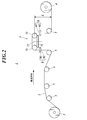
- FIG. 2 is a front view showing a schematic configuration of the sheet member conveying apparatus according to the present embodiment.
- the sheet member conveying apparatus 1 includes a drawing unit 3 that rotatably holds a sheet member 2 wound in a roll shape, and a winding unit 4 that winds the sheet member 2 in a roll shape.
- the sheet member 2 can be transported by roll-to-roll.
- the winding member 4 winds up the sheet member 2 so that the processing surface is inside.
- a plurality of conveying rollers 5 that support the sheet member 2 are disposed between the drawing unit 3 and the winding unit 4.
- a correction mechanism 7 is provided between the conveying rollers 5 disposed on the winding unit 4 side to hold a part of the sheet member 2 so as to be one step higher than the other parts.
- a deviation detection unit 6 that detects a positional deviation in the width direction of the sheet member 2 is provided on the downstream side of the correction mechanism 7 in the conveyance direction.
- an auxiliary sheet detection unit 8 that detects whether the resin film 22 faces the correction mechanism 7 is provided on the upstream side of the correction mechanism 7 in the transport direction.
- the auxiliary sheet detection unit 8 is preferably disposed on the upstream side of the correction mechanism 7 as described above, but may be disposed on the downstream side of the correction mechanism 7.
- the misalignment detection unit 6 includes a light emitting unit 61 and a light receiving unit 62 that receives light from the light emitting unit 61, and these are opposed so as to sandwich the edge of the sheet member 2. If the amount of light received by the light receiving unit 62 when the edge of the sheet member 2 is not misaligned is a reference value, the sheet member 2 is displaced in the direction in which the light receiving unit 62 is exposed when the amount of received light is larger than the reference value. When the received light amount is smaller than the reference value, it is detected that the sheet member 2 is displaced in the direction covering the light receiving unit 62.
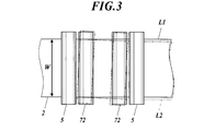
- FIG. 3 is a top view showing a schematic configuration of the correction mechanism 7.
- the correction mechanism 7 includes a base 71 and a pair of correction rollers 72 that are pivotally supported by the base 71.
- the base 71 has a rotation shaft 73 perpendicular to the center thereof, and rotates about the rotation shaft 73. With this rotation, the correction roller 72 also swings with respect to the transport direction. By this swinging, the sheet member 2 is twisted to correct the positional deviation of the sheet member 2.
- the solid line L1 shows the sheet member 2 whose position is shifted.
- the auxiliary sheet detection unit 8 includes a light emitting unit 81 and a light receiving unit 82 that receives light from the light emitting unit 81, and these are opposed so as to sandwich the sheet member 2. And it is possible to detect whether the region facing the auxiliary sheet detection unit 8 is the thin film glass 21 or the resin film 22 by detecting a change in the amount of transmitted light.
- the resin film 22 is opposed to the correction mechanism 7 based on the length of the resin film 22, the distance from the correction mechanism 7 to the auxiliary sheet detection unit 8, the conveyance speed, the switching timing between the resin film 22 and the thin film glass 21, and the like. Whether or not it is detected.
- the auxiliary film detection unit 8 detects the resin film 22, and the resin film 22 faces the correction mechanism 7 depending on its transit time and conveyance speed. It is possible to detect whether or not. At this time, if the deviation detection unit 6 detects a positional deviation, the correction mechanism 7 is activated.
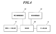
- FIG. 4 is a block diagram showing a main control configuration in the sheet member conveying apparatus 1.
- the control unit 10 includes a CPU, a RAM, and a ROM.
- the control unit 10 includes a correction mechanism drive source 11 that is a drive source of the correction mechanism 7 and a drive source of the winding unit 4.
- a winding unit drive source 12, a displacement detection unit 6, and an auxiliary sheet detection unit 8 are electrically connected.
- the control unit 10 detects the correction mechanism of the correction mechanism 7.
- the position deviation is corrected by controlling the drive source 11 and twisting the resin film 22 portion of the sheet member 2 with respect to the transport direction.
- the control unit 10 controls the winding unit drive source 12 to start conveying the sheet member 2.
- the control unit 10 inputs the detection result of the auxiliary sheet detection unit 8 that the resin film 22 faces the correction mechanism 7.
- the sheet member 2 continues to be conveyed until
- the control unit 10 recognizes the position shift correction timing and controls the correction mechanism drive source 11. Then, the base 71 of the correction mechanism 7 is rotated.
- the pair of correction rollers 72 is also swung, and the resin film 22 portion of the sheet member 2 is twisted, and the positional deviation of the sheet member 2 is corrected.
- the control unit 10 May wait until the next resin film 22 faces the correction mechanism 7, or may correct the displacement of the thin film glass 21 facing the correction mechanism 7.
- the correction of the positional deviation with respect to the thin film glass 21 is performed for a pair of corrections so that the stress is smaller than the correction of the positional deviation with respect to the resin film 22.
- the inclination angle of the roller 72 is reduced.
- the control unit 10 constantly monitors the detection result of the deviation detection unit 6, and when the detection result indicates that there is no position deviation, the control unit 10 controls the correction mechanism drive source 11 to release the inclination of the pair of correction rollers 72.
- the resin film 22 portion which is the auxiliary sheet portion of the sheet member 2
- the positional shift is corrected, so the stress due to the positional shift correction is It acts on the resin film 22.
- the stress due to the misalignment correction is less likely to affect the thin film glass 21, and the thin film glass 21 can be prevented from being damaged.
- a good roll can be obtained at the winding unit 4 by correcting the positional deviation. Accordingly, it is possible to greatly suppress a conveyance failure or a processing position failure caused by winding misalignment during unwinding in the next process.
- the auxiliary sheet portion is a resin film 22 having higher toughness than the thin film glass 21, it is more likely that the positional deviation correction is performed on the resin film 22 than the thin film glass 21 is corrected. Can be prevented.
- the present invention is not limited to the above embodiment, and can be modified as appropriate.
- the same parts as those in the above embodiment are denoted by the same reference numerals and the description thereof is omitted.
- the relationship between the distance L from the center of the pair of correction rollers 72 to the lower end of the conveying roller 5 and the width W of the sheet member 2 preferably satisfies the relationship of Equation (3). It is more preferable that the relationship (4) is satisfied.
- the resin film 22 can be prevented from being twisted suddenly during the correction of the positional deviation, so that there is no possibility that the resin film 22 is distorted or plastically deformed. .
- the length along the conveying direction of one resin film 22 is Pl, and the width of the sheet member 2 perpendicular to the length direction is W.
- the relationship of the formula (3) it is preferable that the relationship of the formula (1) is satisfied.
- seat detection part 8 has distinguished the thin film glass 21 and the resin film 22 with the difference in the light transmittance
- the thin film glass 21 and the resin film 22 can be distinguished
- Other methods may be used as long as they are present. For example, there is a method of distinguishing the types by detecting the difference in thickness between the two using a planar shape sensor or a displacement sensor.
- the positional deviation is corrected by twisting the resin film 22 portion with respect to the conveyance direction, but the method of correcting the positional deviation is not limited to this. .
- a method of correcting the positional deviation by operating the correction roller 72 in the axial direction can also be mentioned.
- the sheet member conveying method and conveying apparatus according to the present invention may be used in the conveying field for conveying sheet members such as thin film glass.
Landscapes
- Registering, Tensioning, Guiding Webs, And Rollers Therefor (AREA)
- Controlling Rewinding, Feeding, Winding, Or Abnormalities Of Webs (AREA)
Abstract
シート部材(2)をロールトゥロールで搬送する方法は、シート部材(2)の位置ズレを補正することを含む。シート部材(2)は、当該シート部材(2)の延在方向に沿って配列された複数の薄膜ガラス(21)と、複数の薄膜ガラス(21)の間に配置された樹脂フィルム(22)とを備える。シート部材(2)の搬送経路上に配置された補正機構(7)は、位置ズレの補正タイミングになると、シート部材(2)における樹脂フィルム(22)に対して位置ズレの補正を施す。薄膜ガラス(21)の位置ズレが補正される際の薄膜ガラス(21)の破損が抑制される。
Description
本発明はシート部材の搬送方法及び搬送装置に関する。
従来から、タッチパネルや携帯電話、電子ペーパー、各種太陽電池、各種エレクトロルミネッセンス調光素子等の各種電子デバイスに用いられる基材として、柔軟性及び生産性の観点からガラス基材に代わってフレキシブル基材が注目されている。とりわけ、これらのフレキシブル基材には、樹脂材料が用いられてきたが、当該樹脂材料は、ガラスと比較すると、耐えられる温度に限界があることや水蒸気透過率及び酸素透過率が低いことが問題であった。
このような問題から、近年では、フレキシブル基材として薄膜ガラスといった、厚さ数百μm以下といった極めて薄いガラスが注目されている。しかしながら、この薄膜ガラスは、厚さ数百μm以下といった極めて薄いことから、薄膜ガラスの端部に生じた微細なクラックに応力が集中することで簡単に破損してしまい、上述したような電子デバイスの製造工程、特に搬送工程では薄膜ガラスの扱いが非常に困難であった。
このような問題から、近年では、フレキシブル基材として薄膜ガラスといった、厚さ数百μm以下といった極めて薄いガラスが注目されている。しかしながら、この薄膜ガラスは、厚さ数百μm以下といった極めて薄いことから、薄膜ガラスの端部に生じた微細なクラックに応力が集中することで簡単に破損してしまい、上述したような電子デバイスの製造工程、特に搬送工程では薄膜ガラスの扱いが非常に困難であった。
ところで、上述したような電子デバイスの生産性を向上させるための一つの方法としてフレキシブル基材をロールトゥロールで搬送することが挙げられる。このロールトゥロール搬送は、リジットな基材には適用できず、フレキシブルな基材の利点の一つである。フレキシブル基材は、このロールトゥロール搬送を行うことによって、結果としてデバイスの連続生産が可能となっている。
このようなロールトゥロール搬送を行って薄膜ガラスを搬送する技術が開示されている(例えば特許文献1参照)。この文献には、ロール状に巻かれた薄膜ガラスを引き出す際に、その引き出された薄膜ガラスの先端部が破断するおそれがあるため、当該先端部に樹脂フィルムを接合して、薄膜ガラスの先端部の破断を防止することが記載されている。
このようなロールトゥロール搬送を行って薄膜ガラスを搬送する技術が開示されている(例えば特許文献1参照)。この文献には、ロール状に巻かれた薄膜ガラスを引き出す際に、その引き出された薄膜ガラスの先端部が破断するおそれがあるため、当該先端部に樹脂フィルムを接合して、薄膜ガラスの先端部の破断を防止することが記載されている。
ここで、通常、薄膜ガラス等のシート部材の搬送装置には、搬送時に位置ズレを補正するための補正機構が搭載されているが、当該補正機構による補正は薄膜ガラスに捻れ等の応力を発生させて行っているため、この捻れ等の応力により当該薄膜ガラスのクラックから薄膜ガラスが破損してしまう可能性があった。上述した特許文献1のように、ロール状に巻かれた薄膜ガラスの先端部のみを樹脂フィルムと接合していたとしても、補正機構が稼働するのは先端部に接合された樹脂フィルムの部分だけには限らず、薄膜ガラスの部分で補正機構が稼働することもあるために、結果として薄膜ガラスが破損してしまうおそれがある。
本発明の課題は、搬送時に薄膜ガラスの位置ズレを補正する際に、薄膜ガラスの破損を防止することである。
本発明の課題は、搬送時に薄膜ガラスの位置ズレを補正する際に、薄膜ガラスの破損を防止することである。
請求項1記載の発明は、
シート部材をロールトゥロールで搬送するシート部材の搬送方法において、
前記シート部材は、当該シート部材の延在方向に沿って配列された複数の薄膜ガラスと、複数の前記薄膜ガラスの間に少なくとも一つ介在するように配置された補助シート部とを備え、
前記シート部材の搬送経路上に配置され、当該シート部材の幅方向の位置ズレを補正する補正機構が、前記位置ズレの補正タイミングになると、前記シート部材における補助シート部分に対して前記位置ズレの補正を施すことを特徴としている。
シート部材をロールトゥロールで搬送するシート部材の搬送方法において、
前記シート部材は、当該シート部材の延在方向に沿って配列された複数の薄膜ガラスと、複数の前記薄膜ガラスの間に少なくとも一つ介在するように配置された補助シート部とを備え、
前記シート部材の搬送経路上に配置され、当該シート部材の幅方向の位置ズレを補正する補正機構が、前記位置ズレの補正タイミングになると、前記シート部材における補助シート部分に対して前記位置ズレの補正を施すことを特徴としている。
請求項2記載の発明は、請求項1記載のシート部材の搬送方法において、
前記補助シート部は、前記薄膜ガラスよりもじん性が高いことを特徴としている。
前記補助シート部は、前記薄膜ガラスよりもじん性が高いことを特徴としている。
請求項3記載の発明は、請求項2記載のシート部材の搬送方法において、
前記補助シート部は樹脂フィルムであることを特徴としている。
前記補助シート部は樹脂フィルムであることを特徴としている。
請求項4記載の発明は、請求項1~3のいずれか一項に記載のシート部材の搬送方法において、
前記位置ズレの補正は、前記シート部材における前記補助シート部を搬送方向に対して捻ることで行われることを特徴としている。
前記位置ズレの補正は、前記シート部材における前記補助シート部を搬送方向に対して捻ることで行われることを特徴としている。
請求項5記載の発明は、請求項1~4のいずれか一項に記載のシート部材の搬送方法において、
一つの前記補助シート部の長さをPlとし、前記シート部材の幅をWとすると、式(1)の関係を満たしていることを特徴としている。
Pl≧W・・・(1)
一つの前記補助シート部の長さをPlとし、前記シート部材の幅をWとすると、式(1)の関係を満たしていることを特徴としている。
Pl≧W・・・(1)
請求項6記載の発明は、請求項1~4のいずれか一項に記載のシート部材の搬送方法において、
一つの前記補助シート部の長さをPlとし、前記シート部材の幅をWとすると、式(2)の関係を満たしていることを特徴としている。
Pl≧3W/2・・・(2)
一つの前記補助シート部の長さをPlとし、前記シート部材の幅をWとすると、式(2)の関係を満たしていることを特徴としている。
Pl≧3W/2・・・(2)
請求項7記載の発明は、
延在方向に沿って配列された複数の薄膜ガラスと、複数の前記薄膜ガラスの間に少なくとも一つ介在するように配置された補助シート部とを備えたシート部材をロールトゥロールで搬送するシート部材の搬送装置であって、
前記シート部材の幅方向の位置ズレを検出するズレ検出部と、
前記シート部材の搬送経路上に配置され、前記シート部材の幅方向の位置ズレを補正する補正機構と、
前記補助シート部が前記補正機構に対向したか否かを検出する補助シート検出部と、
前記ズレ検出部及び前記補助シート検出部の検出結果に基づいて前記補正機構を制御する制御部とを備え、
前記制御部は、前記ズレ検出部によって前記シート部材の位置ズレが検出され、なおかつ前記補助シート検出部によって前記補助シート部が前記補正機構に対向したことが検出されると、前記補正機構を制御して、前記シート部材における前記補助シート部に対して前記位置ズレの補正を施すことを特徴としている。
延在方向に沿って配列された複数の薄膜ガラスと、複数の前記薄膜ガラスの間に少なくとも一つ介在するように配置された補助シート部とを備えたシート部材をロールトゥロールで搬送するシート部材の搬送装置であって、
前記シート部材の幅方向の位置ズレを検出するズレ検出部と、
前記シート部材の搬送経路上に配置され、前記シート部材の幅方向の位置ズレを補正する補正機構と、
前記補助シート部が前記補正機構に対向したか否かを検出する補助シート検出部と、
前記ズレ検出部及び前記補助シート検出部の検出結果に基づいて前記補正機構を制御する制御部とを備え、
前記制御部は、前記ズレ検出部によって前記シート部材の位置ズレが検出され、なおかつ前記補助シート検出部によって前記補助シート部が前記補正機構に対向したことが検出されると、前記補正機構を制御して、前記シート部材における前記補助シート部に対して前記位置ズレの補正を施すことを特徴としている。
請求項8記載の発明は、請求項7記載のシート部材の搬送装置において、
前記補助シート部は、前記薄膜ガラスよりもじん性が高いことを特徴としている。
前記補助シート部は、前記薄膜ガラスよりもじん性が高いことを特徴としている。
請求項9記載の発明は、請求項8記載のシート部材の搬送装置において、
前記補助シート部は樹脂フィルムであることを特徴としている。
前記補助シート部は樹脂フィルムであることを特徴としている。
請求項10記載の発明は、請求項7~9のいずれか一項に記載のシート部材の搬送装置において、
前記位置ズレの補正は、前記シート部材における前記補助シート部を搬送方向に対して捻ることで行われることを特徴としている。
前記位置ズレの補正は、前記シート部材における前記補助シート部を搬送方向に対して捻ることで行われることを特徴としている。
請求項11記載の発明は、請求項7~10のいずれか一項に記載のシート部材の搬送装置において、
一つの前記補助シート部の長さをPlとし、前記シート部材の幅をWとすると、式(1)の関係を満たしていることを特徴としている。
Pl≧W・・・(1)
一つの前記補助シート部の長さをPlとし、前記シート部材の幅をWとすると、式(1)の関係を満たしていることを特徴としている。
Pl≧W・・・(1)
請求項12記載の発明は、請求項7~10のいずれか一項に記載のシート部材の搬送装置において、
一つの前記補助シート部の長さをPlとし、前記シート部材の幅をWとすると、式(2)の関係を満たしていることを特徴としている。
Pl≧3W/2・・・(2)
一つの前記補助シート部の長さをPlとし、前記シート部材の幅をWとすると、式(2)の関係を満たしていることを特徴としている。
Pl≧3W/2・・・(2)
本発明によれば、搬送時に薄膜ガラスの位置ズレを補正する際に、薄膜ガラスが破損してしまうことを抑制することができる。
以下に、本発明を実施するための最良の形態について図面を用いて説明する。ただし、以下に述べる実施形態には、本発明を実施するために技術的に好ましい種々の限定が付されているが、発明の範囲を以下の実施形態及び図示例に限定するものではない。
本実施形態に係るシート部材の搬送装置は、例えば薄膜ガラスに対して有機EL層を形成する塗布装置或いは蒸着装置内に内蔵されている。ここで塗布方式としては例えば、ダイコーター方式やインクジェット方式が挙げられる。
図1は本実施形態に係るシート部材2の概略構成を示す上面図である。図1に示すようにシート部材2には、それぞれ光透過率の異なる薄膜ガラス21と、補助シート部としての樹脂フィルム22とが延在方向に交互に配列されている。薄膜ガラス21は樹脂フィルム22よりも長く設定されている。薄膜ガラス21と樹脂フィルム22とは接合テープ23によって接合されている。
なお、本実施形態では、薄膜ガラス21と樹脂フィルム22とが交互に配列されたシート部材2を例示して説明したが、シート部材としては、当該シート部材の延在方向に沿って配列された複数の薄膜ガラスと、複数の薄膜ガラスの間に少なくとも一つ介在するように配置された補助シート部とを備えたものであればよい。一例を示すと、薄膜ガラス21、補助シート部、補助シート部、薄膜ガラス21、補助シート部、補助シート部、という具合に薄膜ガラス21の間に、補助シート部が2枚介在したものが挙げられる。
そして、補助シート部としては樹脂フィルム22でなくとも、薄膜ガラス21よりもじん性の高いものであることが好ましく、さらに好ましくは樹脂フィルム以上にじん性が高いものである。
図1は本実施形態に係るシート部材2の概略構成を示す上面図である。図1に示すようにシート部材2には、それぞれ光透過率の異なる薄膜ガラス21と、補助シート部としての樹脂フィルム22とが延在方向に交互に配列されている。薄膜ガラス21は樹脂フィルム22よりも長く設定されている。薄膜ガラス21と樹脂フィルム22とは接合テープ23によって接合されている。
なお、本実施形態では、薄膜ガラス21と樹脂フィルム22とが交互に配列されたシート部材2を例示して説明したが、シート部材としては、当該シート部材の延在方向に沿って配列された複数の薄膜ガラスと、複数の薄膜ガラスの間に少なくとも一つ介在するように配置された補助シート部とを備えたものであればよい。一例を示すと、薄膜ガラス21、補助シート部、補助シート部、薄膜ガラス21、補助シート部、補助シート部、という具合に薄膜ガラス21の間に、補助シート部が2枚介在したものが挙げられる。
そして、補助シート部としては樹脂フィルム22でなくとも、薄膜ガラス21よりもじん性の高いものであることが好ましく、さらに好ましくは樹脂フィルム以上にじん性が高いものである。
図2は本実施形態に係るシート部材の搬送装置の概略構成を示す正面図である。
図2に示すように、シート部材の搬送装置1は、ロール状に巻かれたシート部材2を回転自在に保持する引出部3と、シート部材2をロール状に巻き取る巻取部4とを備えており、これによりシート部材2をロールトゥロールで搬送できるようになっている。本実施形態では、シート部材2の上面が処理面であるので、巻取部4では処理面が内側となるようにシート部材2を巻き取っている。そして、引出部3と、巻取部4との間には、シート部材2を支持する複数の搬送ローラ5が配置されている。ここで、巻取部4側に配置された搬送ローラ5の間には、シート部材2の一部が他の部分とは一段高くなるように保持する補正機構7が設けられている。搬送方向における補正機構7の下流側には、シート部材2の幅方向の位置ズレを検出するズレ検出部6が設けられている。また、搬送方向における補正機構7の上流側には樹脂フィルム22が補正機構7に対向したか否かを検出する補助シート検出部8が設けられている。なお、補助シート検出部8は、前述したように補正機構7の上流側に配置されていることが好ましいが、補正機構7の下流側に配置されていてもよい。
図2に示すように、シート部材の搬送装置1は、ロール状に巻かれたシート部材2を回転自在に保持する引出部3と、シート部材2をロール状に巻き取る巻取部4とを備えており、これによりシート部材2をロールトゥロールで搬送できるようになっている。本実施形態では、シート部材2の上面が処理面であるので、巻取部4では処理面が内側となるようにシート部材2を巻き取っている。そして、引出部3と、巻取部4との間には、シート部材2を支持する複数の搬送ローラ5が配置されている。ここで、巻取部4側に配置された搬送ローラ5の間には、シート部材2の一部が他の部分とは一段高くなるように保持する補正機構7が設けられている。搬送方向における補正機構7の下流側には、シート部材2の幅方向の位置ズレを検出するズレ検出部6が設けられている。また、搬送方向における補正機構7の上流側には樹脂フィルム22が補正機構7に対向したか否かを検出する補助シート検出部8が設けられている。なお、補助シート検出部8は、前述したように補正機構7の上流側に配置されていることが好ましいが、補正機構7の下流側に配置されていてもよい。
ズレ検出部6は、発光部61と、発光部61からの光を受光する受光部62とを備えていて、これらがシート部材2の縁を挟むように対向している。シート部材2の縁が位置ズレのない場合における受光部62での受光量を基準値とすると、受光量が基準値より大きい場合にはシート部材2が受光部62を露出させる方向に位置ズレしており、受光量が基準値より小さい場合にはシート部材2が受光部62を覆う方向に位置ズレしていることが検出される。
図3は補正機構7の概略構成を示す上面図である。図2及び図3に示すように、補正機構7は、基台71と、基台71に軸支された一対の補正用ローラ72とが備えられている。基台71は、その中心に垂直な回転軸73を備えていて、当該回転軸73を中心に回転する。この回転に伴って補正用ローラ72も搬送方向に対して揺動する。この揺動によってシート部材2を捻ってシート部材2の位置ズレを補正するようになっている。例えば図3では、実線L1が位置のずれたシート部材2を示している。この状態で、補正機構7の基台71を回転させて、一対の補正用ローラ72を揺動させると、その揺動に追従してシート部材2が捻れ、位置ズレが補正される(図3の一点鎖線L2参照)。なお、逆方向への位置ズレを補正する場合には、基台71を逆回転させて、一対の補正用ローラ72を逆方向へ傾かせる。
補助シート検出部8は、図2に示すように発光部81と、発光部81からの光を受光する受光部82とを備えていて、これらがシート部材2を挟むように対向している。そして、透過光の受光量変化を検出することで、補助シート検出部8に対向している領域が薄膜ガラス21であるか、樹脂フィルム22であるかを検出できるようになっている。そして、樹脂フィルム22の長さ、補正機構7から補助シート検出部8までの距離、搬送速度、樹脂フィルム22と薄膜ガラス21との切り替わりタイミング等から、補正機構7に樹脂フィルム22が対向しているか否かを検出するようになっている。具体的には、予め樹脂フィルム22の長さが記憶されていると、補助シート検出部8で樹脂フィルム22が検出され、その通過時間と搬送速度とによって樹脂フィルム22が補正機構7に対向したか否かを検出できるようになっている。このときにズレ検出部6が位置ズレを検出していると、補正機構7が稼働するようになっている。
図4は、シート部材の搬送装置1における主制御構成を示すブロック図である。図4に示すように、制御部10は、CPU、RAM、ROMを備えており、制御部10には補正機構7の駆動源である補正機構駆動源11と、巻取部4の駆動源である巻取部駆動源12と、ズレ検出部6と、補助シート検出部8とが電気的に接続されている。
制御部10は、ズレ検出部6によってシート部材2の位置ズレが検出され、なおかつ補助シート検出部8によって樹脂フィルム22が補正機構7に対向したことが検出されると、補正機構7の補正機構駆動源11を制御して、シート部材2における樹脂フィルム22部分を搬送方向に対して捻ることで位置ズレを補正するようになっている。
制御部10は、ズレ検出部6によってシート部材2の位置ズレが検出され、なおかつ補助シート検出部8によって樹脂フィルム22が補正機構7に対向したことが検出されると、補正機構7の補正機構駆動源11を制御して、シート部材2における樹脂フィルム22部分を搬送方向に対して捻ることで位置ズレを補正するようになっている。
次に、本実施形態のシート部材2の搬送方法について説明する。
搬送開始に伴い、制御部10は巻取部駆動源12を制御してシート部材2の搬送を開始する。搬送途中に、ズレ検出部6によってシート部材2の位置ズレが検出されると、制御部10は、樹脂フィルム22が補正機構7に対向したとの補助シート検出部8の検出結果が入力されるまでそのままシート部材2の搬送を継続する。そして、補助シート検出部8から樹脂フィルム22が補正機構7に対向したとの検出結果が入力されると、制御部10は位置ズレの補正タイミングと認識して、補正機構駆動源11を制御し、補正機構7の基台71を回転させる。これにより一対の補正用ローラ72も揺動しシート部材2の樹脂フィルム22部分が捻られ、シート部材2の位置ズレが補正される。
なお、このとき、樹脂フィルム22部分に対して位置ズレの補正を施したにも関わらず、位置ズレが完全に補正されずに樹脂フィルム22が補正機構7を通過した場合には、制御部10は、次の樹脂フィルム22が補正機構7に対向するまで待つか、或いは、補正機構7に対向した薄膜ガラス21に対して位置ズレの補正を施してもよい。その際、樹脂フィルム22に比較して薄膜ガラス21は破損しやすいため、薄膜ガラス21に対する位置ズレの補正は、樹脂フィルム22に対する位置ズレの補正よりも応力が小さくなるように、一対の補正用ローラ72の傾斜角度を小さくしておく。
搬送開始に伴い、制御部10は巻取部駆動源12を制御してシート部材2の搬送を開始する。搬送途中に、ズレ検出部6によってシート部材2の位置ズレが検出されると、制御部10は、樹脂フィルム22が補正機構7に対向したとの補助シート検出部8の検出結果が入力されるまでそのままシート部材2の搬送を継続する。そして、補助シート検出部8から樹脂フィルム22が補正機構7に対向したとの検出結果が入力されると、制御部10は位置ズレの補正タイミングと認識して、補正機構駆動源11を制御し、補正機構7の基台71を回転させる。これにより一対の補正用ローラ72も揺動しシート部材2の樹脂フィルム22部分が捻られ、シート部材2の位置ズレが補正される。
なお、このとき、樹脂フィルム22部分に対して位置ズレの補正を施したにも関わらず、位置ズレが完全に補正されずに樹脂フィルム22が補正機構7を通過した場合には、制御部10は、次の樹脂フィルム22が補正機構7に対向するまで待つか、或いは、補正機構7に対向した薄膜ガラス21に対して位置ズレの補正を施してもよい。その際、樹脂フィルム22に比較して薄膜ガラス21は破損しやすいため、薄膜ガラス21に対する位置ズレの補正は、樹脂フィルム22に対する位置ズレの補正よりも応力が小さくなるように、一対の補正用ローラ72の傾斜角度を小さくしておく。
制御部10は、ズレ検出部6の検出結果を常にモニタリングしており、当該検出結果が位置ズレなしとなると、補正機構駆動源11を制御して一対の補正用ローラ72の傾きを解除する。
以上のように、本実施形態によれば、シート部材2の補助シート部である樹脂フィルム22部分が補正機構7と対向した際に、位置ズレの補正が行われるので、位置ズレ補正による応力は樹脂フィルム22に対して作用する。このため、位置ズレ補正による応力が薄膜ガラス21に影響しにくくなり、薄膜ガラス21の破損を防止することができる。
また、位置ズレが補正されることによって巻取部4では良好な巻物が得られることになる。したがって、次工程での巻き出し時に巻きズレによって生じる搬送不良や処理位置不良等を大幅に抑えることができる。
さらに、補助シート部が薄膜ガラス21よりもじん性が高い樹脂フィルム22であるので、薄膜ガラス21に対して位置ズレ補正を行うよりも、樹脂フィルム22部分に位置ズレ補正を行った方が破損を防止することができる。
また、位置ズレが補正されることによって巻取部4では良好な巻物が得られることになる。したがって、次工程での巻き出し時に巻きズレによって生じる搬送不良や処理位置不良等を大幅に抑えることができる。
さらに、補助シート部が薄膜ガラス21よりもじん性が高い樹脂フィルム22であるので、薄膜ガラス21に対して位置ズレ補正を行うよりも、樹脂フィルム22部分に位置ズレ補正を行った方が破損を防止することができる。
なお、本発明は上記実施形態に限らず適宜変更可能である。なお、以下の説明において上記実施形態と同一部分においては同一符号を付してその説明を省略する。
例えば、一対の補正用ローラ72の中心から搬送ローラ5の下端までの距離Lと、シート部材2の幅Wとの関係は、式(3)の関係を満たしていることが好ましく、さらには式(4)の関係を満たしているとより好ましい。例えば、式(3)の関係を満たしていると、位置ズレの補正の際に樹脂フィルム22が急激に捻られることを防止できるため、樹脂フィルム22がツレたり、塑性変形してしまうおそれがない。また、この状態で巻き取ると段差になって製品として必要な薄膜ガラス21に接触することを防止できるので好ましい。さらに、接触は許容されるが破損しやすい薄膜ガラス21に局所的な応力がかかることがないので、破損するおそれもない。
例えば、一対の補正用ローラ72の中心から搬送ローラ5の下端までの距離Lと、シート部材2の幅Wとの関係は、式(3)の関係を満たしていることが好ましく、さらには式(4)の関係を満たしているとより好ましい。例えば、式(3)の関係を満たしていると、位置ズレの補正の際に樹脂フィルム22が急激に捻られることを防止できるため、樹脂フィルム22がツレたり、塑性変形してしまうおそれがない。また、この状態で巻き取ると段差になって製品として必要な薄膜ガラス21に接触することを防止できるので好ましい。さらに、接触は許容されるが破損しやすい薄膜ガラス21に局所的な応力がかかることがないので、破損するおそれもない。
L≧W・・・(3)
L≧3W/2・・・(4)
L≧3W/2・・・(4)
上述したように、位置ズレ補正は樹脂フィルム22に対して施されるので、一つの樹脂フィルム22の搬送方向に沿った長さをPlとし、長さ方向に直交するシート部材2の幅をWとして、式(3)の関係を当てはめると式(1)の関係を満たしていることが好ましい。
Pl≧W・・・(1)
同様に式(4)の関係を当てはめると式(2)の関係を満たしていることがより好ましい。
Pl≧3W/2・・・(2)
また、上記実施形態では補助シート検出部8が光透過率の差によって薄膜ガラス21と樹脂フィルム22とを見分けている場合を例示しているが、薄膜ガラス21と樹脂フィルム22とを区別できるのであればその他の手法を用いても構わない。例えば、平面形状センサーや変位センサーによって、両者の厚みの違いを検出することで種類を見分ける手法が挙げられる。
また、本実施形態では、樹脂フィルム22部分を搬送方向に対して捻ることで位置ズレを補正している場合を例示しているが、位置ズレの補正の方法はこれに限定されるものではない。例えば、補正用ローラ72を軸方向に動作させることで位置ズレを補正する手法も挙げられる。
本発明に係るシート部材の搬送方法及び搬送装置は、薄膜ガラス等のシート部材を搬送する搬送分野において利用可能性がある。
1 搬送装置(シート部材の搬送装置)
2 シート部材
3 引出部
4 巻取部
5 搬送ローラ
6 ズレ検出部
7 補正機構
8 補助シート検出部
10 制御部
11 補正機構駆動源
12 巻取部駆動源
21 薄膜ガラス
22 樹脂フィルム(補助シート部)
23 接合テープ
61 発光部
62 受光部
71 基台
72 補正用ローラ
73 回転軸
81 発光部
82 受光部
2 シート部材
3 引出部
4 巻取部
5 搬送ローラ
6 ズレ検出部
7 補正機構
8 補助シート検出部
10 制御部
11 補正機構駆動源
12 巻取部駆動源
21 薄膜ガラス
22 樹脂フィルム(補助シート部)
23 接合テープ
61 発光部
62 受光部
71 基台
72 補正用ローラ
73 回転軸
81 発光部
82 受光部
Claims (12)
- シート部材をロールトゥロールで搬送するシート部材の搬送方法において、
前記シート部材は、当該シート部材の延在方向に沿って配列された複数の薄膜ガラスと、複数の前記薄膜ガラスの間に少なくとも一つ介在するように配置された補助シート部とを備え、
前記シート部材の搬送経路上に配置され、当該シート部材の幅方向の位置ズレを補正する補正機構が、前記位置ズレの補正タイミングになると、前記シート部材における補助シート部分に対して前記位置ズレの補正を施すことを特徴とするシート部材の搬送方法。 - 請求項1記載のシート部材の搬送方法において、
前記補助シート部は、前記薄膜ガラスよりもじん性が高いことを特徴とするシート部材の搬送方法。 - 請求項2記載のシート部材の搬送方法において、
前記補助シート部は樹脂フィルムであることを特徴とするシート部材の搬送方法。 - 請求項1~3のいずれか一項に記載のシート部材の搬送方法において、
前記位置ズレの補正は、前記シート部材における前記補助シート部を搬送方向に対して捻ることで行われることを特徴とするシート部材の搬送方法。 - 請求項1~4のいずれか一項に記載のシート部材の搬送方法において、
一つの前記補助シート部の長さをPlとし、前記シート部材の幅をWとすると、式(1)の関係を満たしていることを特徴とするシート部材の搬送方法。
Pl≧W・・・(1) - 請求項1~4のいずれか一項に記載のシート部材の搬送方法において、
一つの前記補助シート部の長さをPlとし、前記シート部材の幅をWとすると、式(2)の関係を満たしていることを特徴とするシート部材の搬送方法。
Pl≧3W/2・・・(2) - 延在方向に沿って配列された複数の薄膜ガラスと、複数の前記薄膜ガラスの間に少なくとも一つ介在するように配置された補助シート部とを備えたシート部材をロールトゥロールで搬送するシート部材の搬送装置であって、
前記シート部材の幅方向の位置ズレを検出するズレ検出部と、
前記シート部材の搬送経路上に配置され、前記シート部材の幅方向の位置ズレを補正する補正機構と、
前記補助シート部が前記補正機構に対向したか否かを検出する補助シート検出部と、
前記ズレ検出部及び前記補助シート検出部の検出結果に基づいて前記補正機構を制御する制御部とを備え、
前記制御部は、前記ズレ検出部によって前記シート部材の位置ズレが検出され、なおかつ前記補助シート検出部によって前記補助シート部が前記補正機構に対向したことが検出されると、前記補正機構を制御して、前記シート部材における前記補助シート部に対して前記位置ズレの補正を施すことを特徴とするシート部材の搬送装置。 - 請求項7記載のシート部材の搬送装置において、
前記補助シート部は、前記薄膜ガラスよりもじん性が高いことを特徴とするシート部材の搬送装置。 - 請求項8記載のシート部材の搬送装置において、
前記補助シート部は樹脂フィルムであることを特徴とするシート部材の搬送装置。 - 請求項7~9のいずれか一項に記載のシート部材の搬送装置において、
前記位置ズレの補正は、前記シート部材における前記補助シート部を搬送方向に対して捻ることで行われることを特徴とするシート部材の搬送装置。 - 請求項7~10のいずれか一項に記載のシート部材の搬送装置において、
一つの前記補助シート部の長さをPlとし、前記シート部材の幅をWとすると、式(1)の関係を満たしていることを特徴とするシート部材の搬送装置。
Pl≧W・・・(1) - 請求項7~10のいずれか一項に記載のシート部材の搬送装置において、
一つの前記補助シート部の長さをPlとし、前記シート部材の幅をWとすると、式(2)の関係を満たしていることを特徴とするシート部材の搬送装置。
Pl≧3W/2・・・(2)
Priority Applications (1)
| Application Number | Priority Date | Filing Date | Title |
|---|---|---|---|
| JP2013519446A JP6052173B2 (ja) | 2011-06-08 | 2012-05-29 | シート部材の搬送方法及び搬送装置 |
Applications Claiming Priority (2)
| Application Number | Priority Date | Filing Date | Title |
|---|---|---|---|
| JP2011127806 | 2011-06-08 | ||
| JP2011-127806 | 2011-06-08 |
Publications (1)
| Publication Number | Publication Date |
|---|---|
| WO2012169386A1 true WO2012169386A1 (ja) | 2012-12-13 |
Family
ID=47295954
Family Applications (1)
| Application Number | Title | Priority Date | Filing Date |
|---|---|---|---|
| PCT/JP2012/063700 Ceased WO2012169386A1 (ja) | 2011-06-08 | 2012-05-29 | シート部材の搬送方法及び搬送装置 |
Country Status (2)
| Country | Link |
|---|---|
| JP (1) | JP6052173B2 (ja) |
| WO (1) | WO2012169386A1 (ja) |
Cited By (3)
| Publication number | Priority date | Publication date | Assignee | Title |
|---|---|---|---|---|
| WO2014112542A1 (ja) * | 2013-01-17 | 2014-07-24 | 日東電工株式会社 | 薄ガラス長尺体 |
| CN113788345A (zh) * | 2021-09-15 | 2021-12-14 | 深圳市友利特精密机械制造有限公司 | 一种全自动电容器原材料正负铝箔、电解纸分切机 |
| CN116281332A (zh) * | 2022-12-29 | 2023-06-23 | 成都瑞波科材料科技有限公司 | 一种基于卷对卷工艺的工艺设备 |
Citations (3)
| Publication number | Priority date | Publication date | Assignee | Title |
|---|---|---|---|---|
| JPH11322147A (ja) * | 1998-05-14 | 1999-11-24 | Dainippon Printing Co Ltd | 巻取り装置及び巻取り方法 |
| JP2002164639A (ja) * | 2000-11-27 | 2002-06-07 | Matsushita Electric Works Ltd | 基板の連続処理方法 |
| JP2010132350A (ja) * | 2008-10-01 | 2010-06-17 | Nippon Electric Glass Co Ltd | ガラスロール及びガラスロールの処理方法 |
-
2012
- 2012-05-29 WO PCT/JP2012/063700 patent/WO2012169386A1/ja not_active Ceased
- 2012-05-29 JP JP2013519446A patent/JP6052173B2/ja not_active Expired - Fee Related
Patent Citations (3)
| Publication number | Priority date | Publication date | Assignee | Title |
|---|---|---|---|---|
| JPH11322147A (ja) * | 1998-05-14 | 1999-11-24 | Dainippon Printing Co Ltd | 巻取り装置及び巻取り方法 |
| JP2002164639A (ja) * | 2000-11-27 | 2002-06-07 | Matsushita Electric Works Ltd | 基板の連続処理方法 |
| JP2010132350A (ja) * | 2008-10-01 | 2010-06-17 | Nippon Electric Glass Co Ltd | ガラスロール及びガラスロールの処理方法 |
Cited By (7)
| Publication number | Priority date | Publication date | Assignee | Title |
|---|---|---|---|---|
| WO2014112542A1 (ja) * | 2013-01-17 | 2014-07-24 | 日東電工株式会社 | 薄ガラス長尺体 |
| JP2014136664A (ja) * | 2013-01-17 | 2014-07-28 | Nitto Denko Corp | 薄ガラス長尺体 |
| KR20150095797A (ko) * | 2013-01-17 | 2015-08-21 | 닛토덴코 가부시키가이샤 | 박유리 장척체 |
| US9724890B2 (en) | 2013-01-17 | 2017-08-08 | Nitto Denko Corporation | Thin glass elongated body |
| KR101974693B1 (ko) | 2013-01-17 | 2019-05-02 | 닛토덴코 가부시키가이샤 | 박유리 장척체 |
| CN113788345A (zh) * | 2021-09-15 | 2021-12-14 | 深圳市友利特精密机械制造有限公司 | 一种全自动电容器原材料正负铝箔、电解纸分切机 |
| CN116281332A (zh) * | 2022-12-29 | 2023-06-23 | 成都瑞波科材料科技有限公司 | 一种基于卷对卷工艺的工艺设备 |
Also Published As
| Publication number | Publication date |
|---|---|
| JPWO2012169386A1 (ja) | 2015-02-23 |
| JP6052173B2 (ja) | 2016-12-27 |
Similar Documents
| Publication | Publication Date | Title |
|---|---|---|
| JP5765240B2 (ja) | 帯状のシート基板のための搬送装置及び処理装置、デバイス製造方法 | |
| JP2012236676A (ja) | フィルムの巻きズレ修正装置およびその巻きズレ修正方法 | |
| JP2012236675A (ja) | ガラスフィルムの巻きズレ修正装置およびその巻きズレ修正方法 | |
| EP2514852A1 (en) | Conveyance device for film substrate | |
| JP2010173804A5 (ja) | ||
| TWI526298B (zh) | A manufacturing method of an optical display panel, and a manufacturing system of an optical display panel | |
| JP2019218203A (ja) | ガラスロールの製造方法 | |
| JP6052173B2 (ja) | シート部材の搬送方法及び搬送装置 | |
| WO2019244654A1 (ja) | ガラスロールの製造方法 | |
| WO2012099073A1 (ja) | ガラスロール、ガラスロール製造装置、およびガラスロール製造方法 | |
| CN103328357A (zh) | 玻璃卷、玻璃卷制造装置及玻璃卷制造方法 | |
| WO2011016471A1 (ja) | 薄膜積層体の製造装置 | |
| TWI795366B (zh) | 膜體運送裝置及膜體製造方法 | |
| JP6203234B2 (ja) | 光学的表示装置を連続的に製造する装置及び方法 | |
| JP2008031505A (ja) | 成膜装置および成膜方法 | |
| JP2013131556A (ja) | 基板搬送装置 | |
| JP6049187B2 (ja) | 搬送製膜装置 | |
| JP5347491B2 (ja) | 薄膜形成装置 | |
| JP5573717B2 (ja) | ウェブ搬送装置 | |
| JP5983607B2 (ja) | 有機電子デバイス製造装置 | |
| JP6624981B2 (ja) | 基材搬送処理装置 | |
| JP2010215371A (ja) | 帯状可撓性基板搬送システムおよびそれに用いる搬送位置制御装置 | |
| JP2012001404A (ja) | 薄膜ガラスの搬送装置、及び薄膜ガラスの搬送方法 | |
| JP2015010244A (ja) | 差動排気システム |
Legal Events
| Date | Code | Title | Description |
|---|---|---|---|
| 121 | Ep: the epo has been informed by wipo that ep was designated in this application |
Ref document number: 12797399 Country of ref document: EP Kind code of ref document: A1 |
|
| ENP | Entry into the national phase |
Ref document number: 2013519446 Country of ref document: JP Kind code of ref document: A |
|
| NENP | Non-entry into the national phase |
Ref country code: DE |
|
| 122 | Ep: pct application non-entry in european phase |
Ref document number: 12797399 Country of ref document: EP Kind code of ref document: A1 |