WO2012169306A1 - 車両用情報提供装置 - Google Patents
車両用情報提供装置 Download PDFInfo
- Publication number
- WO2012169306A1 WO2012169306A1 PCT/JP2012/061807 JP2012061807W WO2012169306A1 WO 2012169306 A1 WO2012169306 A1 WO 2012169306A1 JP 2012061807 W JP2012061807 W JP 2012061807W WO 2012169306 A1 WO2012169306 A1 WO 2012169306A1
- Authority
- WO
- WIPO (PCT)
- Prior art keywords
- user
- information providing
- vehicle
- providing apparatus
- vehicle information
- Prior art date
- Legal status (The legal status is an assumption and is not a legal conclusion. Google has not performed a legal analysis and makes no representation as to the accuracy of the status listed.)
- Ceased
Links
Images


Classifications
-
- B—PERFORMING OPERATIONS; TRANSPORTING
- B60—VEHICLES IN GENERAL
- B60K—ARRANGEMENT OR MOUNTING OF PROPULSION UNITS OR OF TRANSMISSIONS IN VEHICLES; ARRANGEMENT OR MOUNTING OF PLURAL DIVERSE PRIME-MOVERS IN VEHICLES; AUXILIARY DRIVES FOR VEHICLES; INSTRUMENTATION OR DASHBOARDS FOR VEHICLES; ARRANGEMENTS IN CONNECTION WITH COOLING, AIR INTAKE, GAS EXHAUST OR FUEL SUPPLY OF PROPULSION UNITS IN VEHICLES
- B60K35/00—Instruments specially adapted for vehicles; Arrangement of instruments in or on vehicles
- B60K35/60—Instruments characterised by their location or relative disposition in or on vehicles
-
- B—PERFORMING OPERATIONS; TRANSPORTING
- B60—VEHICLES IN GENERAL
- B60K—ARRANGEMENT OR MOUNTING OF PROPULSION UNITS OR OF TRANSMISSIONS IN VEHICLES; ARRANGEMENT OR MOUNTING OF PLURAL DIVERSE PRIME-MOVERS IN VEHICLES; AUXILIARY DRIVES FOR VEHICLES; INSTRUMENTATION OR DASHBOARDS FOR VEHICLES; ARRANGEMENTS IN CONNECTION WITH COOLING, AIR INTAKE, GAS EXHAUST OR FUEL SUPPLY OF PROPULSION UNITS IN VEHICLES
- B60K35/00—Instruments specially adapted for vehicles; Arrangement of instruments in or on vehicles
- B60K35/10—Input arrangements, i.e. from user to vehicle, associated with vehicle functions or specially adapted therefor
-
- B—PERFORMING OPERATIONS; TRANSPORTING
- B60—VEHICLES IN GENERAL
- B60K—ARRANGEMENT OR MOUNTING OF PROPULSION UNITS OR OF TRANSMISSIONS IN VEHICLES; ARRANGEMENT OR MOUNTING OF PLURAL DIVERSE PRIME-MOVERS IN VEHICLES; AUXILIARY DRIVES FOR VEHICLES; INSTRUMENTATION OR DASHBOARDS FOR VEHICLES; ARRANGEMENTS IN CONNECTION WITH COOLING, AIR INTAKE, GAS EXHAUST OR FUEL SUPPLY OF PROPULSION UNITS IN VEHICLES
- B60K35/00—Instruments specially adapted for vehicles; Arrangement of instruments in or on vehicles
- B60K35/20—Output arrangements, i.e. from vehicle to user, associated with vehicle functions or specially adapted therefor
-
- B—PERFORMING OPERATIONS; TRANSPORTING
- B60—VEHICLES IN GENERAL
- B60K—ARRANGEMENT OR MOUNTING OF PROPULSION UNITS OR OF TRANSMISSIONS IN VEHICLES; ARRANGEMENT OR MOUNTING OF PLURAL DIVERSE PRIME-MOVERS IN VEHICLES; AUXILIARY DRIVES FOR VEHICLES; INSTRUMENTATION OR DASHBOARDS FOR VEHICLES; ARRANGEMENTS IN CONNECTION WITH COOLING, AIR INTAKE, GAS EXHAUST OR FUEL SUPPLY OF PROPULSION UNITS IN VEHICLES
- B60K35/00—Instruments specially adapted for vehicles; Arrangement of instruments in or on vehicles
- B60K35/20—Output arrangements, i.e. from vehicle to user, associated with vehicle functions or specially adapted therefor
- B60K35/21—Output arrangements, i.e. from vehicle to user, associated with vehicle functions or specially adapted therefor using visual output, e.g. blinking lights or matrix displays
- B60K35/215—Output arrangements, i.e. from vehicle to user, associated with vehicle functions or specially adapted therefor using visual output, e.g. blinking lights or matrix displays characterised by the combination of multiple visual outputs, e.g. combined instruments with analogue meters and additional displays
-
- B—PERFORMING OPERATIONS; TRANSPORTING
- B60—VEHICLES IN GENERAL
- B60K—ARRANGEMENT OR MOUNTING OF PROPULSION UNITS OR OF TRANSMISSIONS IN VEHICLES; ARRANGEMENT OR MOUNTING OF PLURAL DIVERSE PRIME-MOVERS IN VEHICLES; AUXILIARY DRIVES FOR VEHICLES; INSTRUMENTATION OR DASHBOARDS FOR VEHICLES; ARRANGEMENTS IN CONNECTION WITH COOLING, AIR INTAKE, GAS EXHAUST OR FUEL SUPPLY OF PROPULSION UNITS IN VEHICLES
- B60K2360/00—Indexing scheme associated with groups B60K35/00 or B60K37/00 relating to details of instruments or dashboards
- B60K2360/148—Instrument input by voice
-
- B—PERFORMING OPERATIONS; TRANSPORTING
- B60—VEHICLES IN GENERAL
- B60K—ARRANGEMENT OR MOUNTING OF PROPULSION UNITS OR OF TRANSMISSIONS IN VEHICLES; ARRANGEMENT OR MOUNTING OF PLURAL DIVERSE PRIME-MOVERS IN VEHICLES; AUXILIARY DRIVES FOR VEHICLES; INSTRUMENTATION OR DASHBOARDS FOR VEHICLES; ARRANGEMENTS IN CONNECTION WITH COOLING, AIR INTAKE, GAS EXHAUST OR FUEL SUPPLY OF PROPULSION UNITS IN VEHICLES
- B60K2360/00—Indexing scheme associated with groups B60K35/00 or B60K37/00 relating to details of instruments or dashboards
- B60K2360/60—Structural details of dashboards or instruments
- B60K2360/68—Features of instruments
- B60K2360/695—Dial features
-
- B—PERFORMING OPERATIONS; TRANSPORTING
- B60—VEHICLES IN GENERAL
- B60K—ARRANGEMENT OR MOUNTING OF PROPULSION UNITS OR OF TRANSMISSIONS IN VEHICLES; ARRANGEMENT OR MOUNTING OF PLURAL DIVERSE PRIME-MOVERS IN VEHICLES; AUXILIARY DRIVES FOR VEHICLES; INSTRUMENTATION OR DASHBOARDS FOR VEHICLES; ARRANGEMENTS IN CONNECTION WITH COOLING, AIR INTAKE, GAS EXHAUST OR FUEL SUPPLY OF PROPULSION UNITS IN VEHICLES
- B60K35/00—Instruments specially adapted for vehicles; Arrangement of instruments in or on vehicles
- B60K35/50—Instruments characterised by their means of attachment to or integration in the vehicle
Definitions
- the present invention relates to a vehicle information providing apparatus that provides auditory information to a user (vehicle user) using a sounding body including a speaker or a buzzer.
- an alarm buzzer that is a sound generator on the back surface of a circuit board located behind a display means comprising a pointer-type display unit mounted in a vehicle meter. If the driver (user) does not wear a seat belt, the buzzer will sound and the buzzer warning sound (sound) will pass through the slits (holes) provided in the cover that covers the back of the circuit board. Then, it is transmitted to the back of the vehicle instrument, and after that, it is repeatedly reflected (informed) to the user side inside the instrument panel that houses the vehicle instrument.
- the alarm sound is transmitted to the user as a sound leaking from the gap between the vehicle instrument and the instrument panel or through another gap provided inside the instrument panel as a sound leaking from the user's feet or the like.
- a sound leaking from the gap between the vehicle instrument and the instrument panel or through another gap provided inside the instrument panel as a sound leaking from the user's feet or the like.
- the present invention is directed to providing a vehicle information providing apparatus capable of improving acoustic characteristics in order to cope with the above-described problems.
- the present invention is a vehicle information providing apparatus for notifying a user of predetermined information, a display means for displaying the predetermined information to the user, and a display means disposed in front of the display means.
- a cover member having an opening that defines a visible region and a cover that covers an area other than the visible region; and a perspective panel that covers the opening so that the user can see the predetermined information through the opening.
- the cover includes a base that covers an area other than the visible region, and a standing wall that is integrally formed with the base so as to surround the visible region.
- the base includes a vehicle for the user.
- a sounding body that outputs auditory information corresponding to the various states of is provided.
- the present invention is characterized in that the sounding body is disposed in a through-hole portion formed in an opening at a predetermined position of the base portion.
- the sounding body cannot be visually recognized from the user side by a covering member that covers the covering portion when the vehicle information providing device is viewed from the front.
- a gap is provided between the covering member and the covering member.
- the present invention is characterized in that the display means includes a pointer-type display unit provided with a pointer having a linearly extending instruction part and an indicator plate having an indicator part indicated by the instruction part.
- an information providing device for a vehicle that can achieve the initial purpose and can improve the acoustic characteristics of the auditory information providing means for the user.
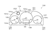
- FIG. 1 is a schematic view of a vehicle information providing apparatus according to an embodiment of the present invention.
- FIG. 1 the general-view figure of the information provision apparatus for vehicles of the state which removed the coating
- FIG. 2 is a cross-sectional view taken along line AA in FIG. 1. The figure which shows an example of the warning information by the embodiment.
- FIG. 1 shows an overview of an example of a vehicle information providing apparatus according to the present embodiment.
- a vehicle information providing apparatus 100 includes first and second display means D1 for displaying various types of vehicle information (predetermined information). , D2 and a vehicle meter (vehicle meter) provided with a notification unit (light emitting display unit) D3.
- the first display means (display means) D1 includes, for example, a pointer-type display unit including a pointer and an indicator plate, which will be described later, and a speedometer disposed in the center of the vehicle information providing apparatus 100 in FIG.
- a third pointer type display unit 103 composed of a fuel gauge arranged on the right side of the.
- the first display unit D1 may be a digital display unit instead of the pointer type display unit, and in this case, the second display unit D2 described later is unnecessary.
- reference numeral 104 denotes a turning member (cover member) placed on each pointer type display unit 101, 102, 103 so as to divide each pointer type display unit 101, 102, 103.
- the facing member 104 is exposed to the outside when a covering member which is a visor described later in FIG. 1 is removed, and is visible from the user side.
- the facing member 104 includes a first opening 104 a made up of a substantially circular window that defines the visible area of the first pointer type display unit 101, and a substantially circular shape that defines the visible area of the second pointer type display unit 102.
- the second opening 104b made of a window
- the third opening 104c made of a substantially circular window that defines the visible area of the third pointer-type display unit 103, and the pointer-type display units 101, 102, 103
- a cover portion 104d that covers an area other than the visible region.
- the first, second, and third see-through panels 105, 106, and 107 are fitted into the openings 104a, 104b, and 104c, respectively.
- the second display means (display unit) D2 includes a display (display panel) such as a liquid crystal display panel or an organic EL panel.
- the first pointer type display unit 101 (in the first pointer type display unit 101). It is arranged so as to face a rectangular opening window 108 formed at the lower center of the indicator plate), and displays various information such as travel distance and fuel consumption.
- the notification unit D3 includes a seat belt non-wearing warning display for notifying the driving state of the vehicle, and is formed at a predetermined position of the indicator plate in the second pointer type display unit 102, for example. That is, since the notification unit D3 is configured to be located behind the second fluoroscopic panel 106, the driver (user) emits and displays a light when a later-described notification light source (light source) is turned on. D3 can be visually recognized through the second perspective panel 106.
- the notification unit D3 serving as a seat belt non-wearing warning display is turned on by the notification light source including the chip-type light emitting diode located immediately below the notification unit D3.
- the seat belt is attached to the seat belt buckle, that is, the seat belt is not worn (that is, the seat belt is not worn). This is to notify that there is.
- the surface of the indicator plate in each display means D1 is set to be substantially the same as the display surfaces of the second display means D2 and the notification unit D3.
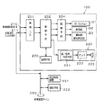
- FIG. 3 is a block diagram showing an electrical configuration of the vehicle information providing apparatus 100.
- a vehicle information terminal 210 and a multiplex communication input / output terminal 211 for inputting / outputting vehicle information a vehicle interface (vehicle I / F) means 201, and a control means 202 for controlling the vehicle information providing apparatus 100.
- a storage means 203 comprising a ROM or the like for storing the processing program, a display control of the second display means D2, a lighting control of the light source for notification, and a drive control of each pointer type display unit 101, 102, 103.
- It has drive means 204 and auditory information providing means 220 composed of a sounding body or the like to be described later that outputs auditory information corresponding to various states of the vehicle to the user.
- the auditory information providing unit 220 includes a sound / sound synthesis unit 221 that reproduces sound / sound, and an amplifier 222 that amplifies an output signal (sound / sound output signal) from the sound / sound synthesis unit 221.
- a substantially circular speaker (sound generator) 223 that outputs an amplified signal from the amplifier 222 is provided, and the sound emitted from the speaker 223 is transmitted through a gap portion described later to a vehicle interior (utilization for driving the vehicle). It is configured to be transmitted to a person).
- the speaker 223 includes a top plate having a hole into which a center pole described later is inserted, a back plate having a center pole protruding from the center, and a space between the two plates so as to surround the center pole.
- a magnetic circuit having a ring-shaped magnet sandwiched between the two, a voice coil disposed in a magnetic gap formed between the center pole and the top plate, and a tip of the voice coil.
- the voice coil When a current is passed through the voice coil, a force acts on the voice coil, and the voice coil It consists of a so-called electrodynamic speaker (cone speaker) that emits sound when the diaphragm vibrates in conjunction with the movement of It is disposed in the through hole portion provided in the later-described cover part of the dial member 104 (base).
- a speaker is used as the sounding body 223.
- a buzzer may be used instead of the speaker.
- FIG. 4 shows a cross-sectional view of the vehicle information providing apparatus 100 (second pointer type display unit 102) along the line AA in FIG.
- a circuit board 301 ; a driving device 303 that is conductively attached to the circuit board 301 and has a rotary shaft 302 extending forward; a pointer 304 that is rotationally driven by the rotary shaft 302; and a circuit board 301 that is positioned behind the pointer 304 Covering the indicator plate 305 disposed above, the turning member 104 that defines the visible region of the indicator plate 305 (second pointer type display unit 102), and the second opening 104b of the turning member 104. It is mainly composed of the above-described second fluoroscopic panel 106 and a visor (covering member) 306 that covers the cover portion 104d of the turning member 104.
- the circuit board 301 is made of, for example, a hard circuit board in which a wiring pattern (not shown) is provided on a glass epoxy base material, and includes a control means 202 that controls the auditory information providing means 220 and a drive that drives and controls the drive device 303.
- Means 204, sound / speech synthesis means 221, amplifier 222, and various circuit components (not shown) such as resistors and capacitors are conductively connected to the wiring pattern.
- the speaker 223 described above is conductively connected to the amplifier 222 via a predetermined wiring member (not shown).
- the driving device 303 is composed of a movable magnet type instrument or a stepping motor, and the main part is mounted behind the circuit board 301 so that the rotating shaft 302 penetrates the circuit board 301, and by a suitable conducting means such as soldering. It is electrically connected to the wiring pattern (drive unit 204).
- the pointer 304 is made of a synthetic resin, and includes an instruction portion 304a that extends linearly so as to indicate an indicator portion (described later) of the indicator plate 305, and a cover (pointer cap) 304b that covers the center of rotation of the indicator portion 304a. ing.
- the indicator plate 305 is made of a synthetic resin such as PC and is formed in a substantially thin plate shape, and an indicator portion 305a made of a scale, a number, and the like indicated by the indicator portion 304a is formed on the surface thereof.
- the indicator portion 305a Are arranged in a substantially arc shape along the rotation trajectory of the pointer 304.
- the indicator plate 305 is provided between the circuit board 301 and the pointer 304 so as to avoid the position where the speaker 223 is disposed.
- the facing member 104 is made of, for example, black synthetic resin, and is disposed in front of the indicator plate 305 to expose the pointer 304 and the indicator portion 305a of the indicator plate 305 to the user (that is, the second pointer-type display portion 102).
- a second opening 104b that defines a visible region of the second pointer 104d and a cover 104d that covers an area other than the visible region of the second pointer-type display unit 102.
- the cover portion 104d is formed in a substantially flat plate shape so as to extend around the second fluoroscopic panel 106, and includes a concealing portion that covers (covers) an area other than the visible region of the second pointer-type display portion 102.
- the base 104e and a standing wall 104f that is integrally formed with the base 104e so as to surround the visible region of the second pointer-type display unit 102.
- the standing wall 104f is formed in a substantially cylindrical shape, It is located between the indicator plate 305 and the base 104e so as to define (enclose) the visible region of the second pointer type display unit 102.
- reference numeral 104g denotes a through-hole portion formed of a substantially circular through-hole formed at a predetermined position of the base portion 104e.
- the through-hole portion 104g is, for example, the first pointer type display portion in FIG.
- the base 104e is provided at a position above the boundary portion between the first pointer type display unit 102 and the second pointer type display unit 102.
- a speaker 223 for outputting auditory information corresponding to various states of the vehicle to the user is appropriately fixed (arranged) in the through hole 104g of the base 104e using a fixing means.
- the second see-through panel 106 is made of, for example, a disc-like light-transmitting synthetic resin, and is arranged at the front opening end of the standing wall 104f so as to close (cover) the second opening 104b of the facing member 104.
- the second fluoroscopic panel 106 is a fluoroscopic part that allows the user to see predetermined information such as the pointer 304, the indicator part 305a, and the notification part D3 (only when the notification light source is turned on) through the second opening 104b. As a function.
- the user can visually recognize (see through) the indicator plate 305 including the pointer 304 and the indicator portion 305a and the notification portion D3 (only when the notification light source is turned on) through the second fluoroscopic panel 106.
- the visor 306 is made of, for example, black synthetic resin, and is disposed on the front side of the cover portion 104d so as to cover the cover portion 104d (base portion 104e) of the facing member 104, and has an opening formed at a position corresponding to the second fluoroscopic panel 106. Hole portion 306a and a covering portion 306b covering the covering portion 104d.
- the speaker 223 since the speaker 223 is embedded (arranged) in the through-hole portion 104g provided in the base portion 104e, the speaker 223 is concealed by the covering portion 306b (visor 306). Become. This is because the speaker 223 cannot be visually recognized by the covering portion 306b (visor 306) that covers the covering portion 104d (base portion 104e) when the vehicle information providing device 100 that is a vehicle instrument is viewed from the user side. It means that it becomes.
- Reference numeral 310 denotes a gap formed between the covering portion 104d and the covering portion 306b (visor 306) in the thickness direction of the vehicle information providing apparatus 100 (the arrow Z direction in FIG. 4).
- the unit 310 has a function as a sound guiding unit for guiding the sound emitted from the speaker 223 to the user side (that is, in front of the vehicle information providing apparatus 100).
- vehicle information providing apparatus 100 is connected to the travel control apparatus 231 and the operation means 232 via the multiple communication line 230 as shown in FIG.
- the control means 202 relates to the vehicle status, alarm information, and operation of the auto cruise and lane keep from the vehicle information terminal 210 and the multiplex communication input / output terminal 211 for inputting and outputting vehicle information.
- Information is obtained, and based on this information, auto cruise, vehicle status notification regarding lane keep, alarm output, guidance for auto cruise, lane keep operation, and answer back are effected through the speaker 223 of the auditory information providing means 220. Sound and voice (and display of the notification unit D3) are performed.
- the control unit 202 obtains information about the vehicle from the vehicle information terminal 210 for inputting / outputting vehicle information and the multiplex communication input / output terminal 211, and determines whether there is a warning generation condition based on this information.
- warning information is notified by the sound information providing means 220 using sound effects and voices, and a display form related to the warning information is displayed by the notification unit D3.
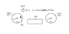
- FIG. 5 shows a specific example thereof.
- the control unit 202 After the sound effect “Pawn”, the auditory information providing means 220 is controlled to output “Please wear your seat belt” by voice. Therefore, the sound effect and the sound output from the speaker 223 in the auditory information providing unit 220 pass through the gap 310 formed between the look-back member 104 (cover 104d) and the visor 306 (cover 306b). By being emitted toward the user's eyes, the user can easily recognize (listen) to the sound effect and the sound.
- the control unit 202 when the detection signal is input via the vehicle information terminal 210 or the multiplex communication input / output terminal 211, the control unit 202 outputs a control signal for turning on the notification light source to the driving unit 204. Upon receiving this control signal, the driving means 204 outputs a driving signal for turning on the notification light source, whereby the notification light source is turned on, and the notification section D3 which is a warning indication that the seat belt is not worn is the second. Light emission is displayed through the fluoroscopic panel 106.
- the sound effect and the sound (auditory information that “please wear a pawn and seat belt”) output from the speaker 223 are formed around the position where the speaker 223 is disposed.
- the information is transmitted directly to the front of the vehicle information providing apparatus 100 (that is, in front of the user's eyes), so that the sound emitted from the speaker 223 is heard from the user without deterioration.
- the notification part D3 which is a warning indication that the seat belt is not worn, is emitted and displayed through the second fluoroscopic panel 106, the sound effect and the sound ("pawn, please wear the seat belt” ”Is emitted toward the user's eyes, so that the user can instantly understand the meaning of the notification content (alarm display) that is emitted and displayed by the notification unit D3.
- HMI Human Machine Interface
- the vehicle information providing apparatus 100 that notifies the user of the predetermined information
- the display unit D1 being a pointer-type display unit for displaying the predetermined information to the user.
- 104a, 104b, 104c are provided with transparent panels 105, 106, 107 that respectively cover the openings 104a, 104b, 104c so that the predetermined information can be seen through to the user through the 104a, 104b, 104c.
- a base 104e that covers an area other than the area, and a standing wall 104f that is integrally formed with the base 104e so as to surround the visible region.
- a speaker (sounding members) 223 for outputting auditory information corresponding to various states of the vehicle to the user is disposed in the base portion 104e.
- the speaker 223 is a through-hole formed at a predetermined position of the base 104e (for example, the base 104e positioned above the boundary portion between the first pointer-type display unit 101 and the second pointer-type display unit 102). It is disposed in the portion 104g.
- the sound effect and the sound (auditory information “please wear a pawn, seat belt”) output from the speaker 223 are not deteriorated (through the gap 310) of the user without the sound pressure. Since it is configured to be transmitted directly in front of the eyes, the user can easily listen to auditory information, thereby providing a vehicle information providing apparatus with good acoustic characteristics.
- the speaker 223 when the speaker 223 is viewed from the vehicle information providing apparatus 100, the speaker 223 is not visible from the user side by the covering portion 306 b (visor 306) covering the covering portion 104 d, and the covering member 104 is provided between the cover 104 and the covering portion 306b (visor 306), so that the sound emitted from the speaker 223 to the user without deteriorating the appearance quality of the vehicle information providing device 100 is provided. (Hearing information) can be transmitted well.
- the example in which the speaker 223 is disposed inside the through hole 104g formed in the base 104e has been described.
- the through hole 104g is abolished and the base 104e (that is, the base 104e) is eliminated.
- the speaker 223 may be placed (arranged) between the cover 306b and the cover 306b.
- the notification unit D3 which is a seat belt non-wearing alarm display, is lit and displayed through the second fluoroscopic panel 106, and at the same time, the speaker 223.
- the sound effect and the sound (that is, the auditory information) output from the user are emitted toward the user's eyes.
- the display means D2 may be configured to display a message (warning message) “Please wear your seat belt”.
- the present invention is applicable to a vehicle information providing apparatus that provides auditory information to a vehicle user using a sounding body including a speaker or a buzzer.
Landscapes
- Engineering & Computer Science (AREA)
- Chemical & Material Sciences (AREA)
- Combustion & Propulsion (AREA)
- Transportation (AREA)
- Mechanical Engineering (AREA)
- Instrument Panels (AREA)
Abstract
音響特性を向上させることが可能な車両用情報提供装置を提供する。 利用者に所定情報を表示するための表示手段D1と、この表示手段D1の前方に配設され表示手段D1の可視領域を定める開口部104a、104b、104cと可視領域以外のエリアを覆う覆い部104dとを有する見返し部材104と、開口部104a、104b、104cを通じて所定情報を利用者に透視可能とするように開口部104a、104b、104cをそれぞれ覆う透視パネル105、106、107とを備え、覆い部104dは、可視領域以外のエリアを覆う基部104eと、可視領域を包囲するように基部104eと一体形成される立壁部104fとを有し、基部104eに設けられた貫通孔部104gには利用者に車両の各種状態に応じた聴覚情報を出力するスピーカ223が配設されている。
Description
本発明は、スピーカまたはブザー等からなる発音体を用いて利用者(車両利用者)に聴覚情報を提供する車両用情報提供装置に関するものである。
従来、この種の車両用情報提供装置にあっては、例えば車両用計器内に搭載された指針式表示部からなる表示手段の背後に位置する回路基板の裏面に発音体である警報用のブザーを取り付け、ドライバー(利用者)がシートベルトを装着していない場合にはブザーを鳴らし、ブザーの警報音(吹鳴音)は回路基板の背後を覆うカバーに設けた複数のスリット(孔)を通って車両用計器の背後へ伝えられ、その後、車両用計器を収納するインパネ内部で反射を繰り返して利用者側に伝わる(報知される)ようになっていた。具体的には、警報音は車両用計器とインパネとの隙間から漏れた音あるいはインパネ内部に設けられた別の隙間を通り利用者の足下等から漏れた音として利用者に伝わる構成であった(例えば下記特許文献1参照)。
しかしながら、上述した特許文献1に記載の車両用情報提供装置の場合、車両用計器の背後へ伝えられるブザー音(前記警報音)は、車両用計器とインパネの隙間で反射を繰り返すため、車両用計器とインパネの形状に応じてブザー音の伝わり方が変わっていた。この結果、車両用計器から同じブザー音を発しても、利用者には車種により異なる音圧、音質として聞こえていた。また利用者には、元来、ブザーが持っている音に対して劣化(変質)した音(前記警報音)が必然的に伝わることから、前記警報音の音響特性が低下してしまう(つまり前記警報音の音圧が不足してしまう、もしくは前記警報音の音質が悪化してしまう)という問題があり、この点で更なる改良の余地が残されていた。
そこで本発明は、前述の課題に対して対処するため、音響特性を向上させることが可能な車両用情報提供装置の提供を目的とするものである。
そこで本発明は、前述の課題に対して対処するため、音響特性を向上させることが可能な車両用情報提供装置の提供を目的とするものである。
本発明は、利用者に所定情報を報知する車両用情報提供装置であって、前記利用者に前記所定情報を表示するための表示手段と、前記表示手段の前方に配設され前記表示手段の可視領域を定める開口部と前記可視領域以外のエリアを覆う覆い部とを有する覆い部材と、前記開口部を通じて前記所定情報を前記利用者に透視可能とするように前記開口部を覆う透視パネルとを備え、前記覆い部は、前記可視領域以外のエリアを覆う基部と、前記可視領域を包囲するように前記基部と一体形成される立壁部とを有し、前記基部には前記利用者に車両の各種状態に応じた聴覚情報を出力する発音体が配設されていることを特徴とする。
また本発明は、前記発音体は、前記基部の所定箇所に開口形成された貫通孔部に配設されていることを特徴とする。
また本発明は、前記発音体は、前記車両用情報提供装置を正視した際に、前記覆い部を覆う被覆部材によって前記利用者側から視認不可能となっており、
前記覆い部材と前記被覆部材との間には間隙部が設けられていることを特徴とする。
前記覆い部材と前記被覆部材との間には間隙部が設けられていることを特徴とする。
また本発明は、前記表示手段は、線状に延びる指示部を有する指針と前記指示部によって指示される指標部を有する指標板とを備えた指針式表示部からなることを特徴とする。
本発明によれば、初期の目的を達成でき、利用者に対する聴覚情報提供手段の音響特性を良好にすることが可能な車両用情報提供装置を提供できる。
以下、添付図面に基づいて本発明の実施形態を説明する。
図1は、本実施形態における車両用情報提供装置の一例の概観図を示すもので、車両用情報提供装置100は、各種車両情報(所定情報)を表示する第1、第2の表示手段D1、D2、並びに報知部(発光表示部)D3を備えた車両用計器(車両用メータ)からなる。
第1の表示手段(表示手段)D1は、例えば後述する指針と指標板とを備えた指針式表示部からなり、図1中、車両用情報提供装置100の中央に配設された速度計からなる第1の指針式表示部101と、この第1の指針式表示部101の左方に配設された回転計からなる第2の指針式表示部102と、第1の指針式表示部101の右方に配設された燃料計からなる第3の指針式表示部103とから構成される。なお、第1の表示手段D1は、指針式表示部ではなく、デジタル表示部であってもよく、この場合、後述する第2の表示手段D2は不要である。
なお、図2中、104は、各指針式表示部101、102、103を区分けするように各指針式表示部101、102、103上に載置された見返し部材(覆い部材)であり、この見返し部材104は、図1において後述するバイザーである被覆部材を取り除いた場合に外部に露出し、利用者側から視認可能となる。
かかる見返し部材104は、第1の指針式表示部101の可視領域を定める略円形の窓部からなる第1の開口部104aと、第2の指針式表示部102の可視領域を定める略円形の窓部からなる第2の開口部104bと、第3の指針式表示部103の可視領域を定める略円形の窓部からなる第3の開口部104cと、各指針式表示部101、102、103の可視領域以外のエリアを覆う覆い部104dとを備えている。そして、各開口部104a、104b、104cには、略円板状の第1、第2、第3の透視パネル105、106、107がそれぞれ嵌め込まれている。
第2の表示手段(表示部)D2は、液晶表示パネルや有機ELパネル等のディスプレイ(表示パネル)からなり、この場合、第1の指針式表示部101(第1の指針式表示部101における前記指標板)の中央下方に形成された矩形状の開口窓部108から臨むように配設され、走行距離や燃費等の各種情報の表示を行うものである。
また報知部D3は、車両の運転状態を報知するシートベルト未着用警告表示からなり、例えば第2の指針式表示部102おける前記指標板の所定箇所に形成されている。つまり、報知部D3は、第2の透視パネル106の背後に位置している構成であるため、運転者(利用者)は、後述する報知用光源(光源)の点灯時に発光表示される報知部D3を第2の透視パネル106を通じて視認することができる。
このシートベルト未着用警報表示としての報知部D3は、シートベルトバックルにシートベルトの固定金具が着用されていない場合、報知部D3の直下に位置するチップ型発光ダイオードからなる前記報知用光源が点灯することで発光表示される発光表示体であり、前記利用者に対して前記シートベルトバックルに前記シートベルトの固定金具が着用されていない状態、つまり前記シートベルトが未着用(未装着)状態であることを報知するものである。なお、本実施形態の場合、各表示手段D1における前記指標板の表面は、第2の表示手段D2並びに報知部D3の表示面と略同一面となるように設定されている。
図3は、車両用情報提供装置100の電気的構成を示すブロック図である。その構成としては、車両情報の入出力を行う車両情報端子210及び多重通信入出力端子211と、車両インターフェース(車両I/F)手段201と、車両用情報提供装置100の制御を行う制御手段202と、処理プログラムを格納するROM等からなる記憶手段203と、第2の表示手段D2の表示制御や前記報知用光源の点灯制御、並びに各指針式表示部101、102、103の駆動制御を行う駆動手段204と、利用者に車両の各種状態に応じた聴覚情報を出力する後述する発音体等をから構成される聴覚情報提供手段220とを有している。
また、聴覚情報提供手段220の構成としては、音/音声を再生する音/音声合成手段221と、この音/音声合成手段221からの出力信号(音/音声出力信号)を増幅するアンプ222と、このアンプ222からの増幅信号を出力する例えば略円形のスピーカ(発音体)223とを備え、このスピーカ223から発せられる音は後述する間隙部を通じて車両内部である車室(車両を運転する利用者)に伝達される構成となっている。
スピーカ223は、本実施形態の場合、後述するセンターポールが挿入される孔部を有するトッププレートと中央部に突出形成されたセンターポールを有するバックプレートと前記センターポールを取り巻くように前記両プレート間に狭持されたリング状マグネットとを備えた磁気回路と、前記センターポールと前記トッププレートとの間に形成される磁気空隙内に配設されるボイスコイルと、このボイスコイルの先端に連結されるコーン型の振動板と、前記磁気回路と前記振動板を所定の位置に支持するフレームとから主に構成され、前記ボイスコイルに電流を流すと前記ボイスコイルに力が作用し、前記ボイスコイルの動きに連動して前記振動板が振動することによって音を発する、所謂、動電型スピーカ(コーンスピーカ)からなり、見返し部材104の後述する覆い部(基部)に設けられる貫通孔部に配設される。なお、本例では、発音体223としてスピーカを用いているが、例えばスピーカに代えてブザーを用いてもよい。
図4は、図1中、A-A線に沿った車両用情報提供装置100(第2の指針式表示部102)の断面図を示しており、かかる第2の指針式表示部102は、回路基板301と、この回路基板301に導通装着され回転軸302が前方に延びる駆動装置303と、回転軸302にて回転駆動される指針304と、この指針304の背後に位置して回路基板301上に配設される指標板305と、この指標板305(第2の指針式表示部102)の可視領域を定める前述した見返し部材104と、この見返し部材104の第2の開口部104bを覆う前述した第2の透視パネル106と、見返し部材104の覆い部104dを覆うバイザー(被覆部材)306とから主に構成されている。
回路基板301は、例えばガラスエポキシ系基材に配線パターン(図示せず)を施した硬質回路基板からなり、聴覚情報提供手段220を制御する制御手段202と、駆動装置303を駆動・制御する駆動手段204と、音/音声合成手段221と、アンプ222と、抵抗、コンデンサ等の各種回路部品(図示せず)とが前記配線パターンに導通接続されている。なお、本例の場合、前述したスピーカ223は、所定の配線部材(図示せず)を介してアンプ222と導通接続されている。
駆動装置303は、可動磁石式計器またはステッピングモータからなり、回転軸302が回路基板301を貫通するように、その主要部が回路基板301の背後に装着され、且つ半田付け等の適宜導通手段により前記配線パターン(駆動部204)に電気接続される。
指針304は、合成樹脂からなり、指標板305の後述する指標部を指示するように線状に延びる指示部304aと、この指示部304aの回転中心部を覆うカバー(指針キャップ)304bとを備えている。
指標板305は、PC等の合成樹脂からなり、略薄板状に形成され、その表面には指示部304aによって指示される目盛、数字等からなる指標部305aが形成され、この場合、指標部305aは指針304の回転軌道に沿って略円弧状に配列されている。なお、指標板305は、スピーカ223の配設位置を避けるように回路基板301と指針304との間に設けられている。
見返し部材104は、例えば黒色の合成樹脂からなり、指標板305の前方に配設され、指針304、指標板305の指標部305aを前記利用者に露出する(つまり第2の指針式表示部102の可視領域を定める)第2の開口部104bと、第2の指針式表示部102の可視領域以外のエリアを覆う覆い部104dとを備えている。
覆い部104dは、第2の透視パネル106の周囲に延在するように略平板状に形成され、第2の指針式表示部102の可視領域以外のエリアを覆う(覆い隠す)隠蔽部からなる基部104eと、第2の指針式表示部102の可視領域を包囲するように基部104eと一体形成される立壁部104fとを有し、立壁部104fは、この場合、略筒状に形成され、第2の指針式表示部102の可視領域を定める(取り囲む)ように、指標板305と基部104eとの間に位置している。
なお、図2中、104gは基部104eの所定箇所に開口形成された略円形の貫通孔からなる貫通孔部であり、かかる貫通孔部104gは、例えば図2中、第1の指針式表示部101と第2の指針式表示部102との境界部分の上方に位置する基部104e箇所に設けられている。ここで、基部104eの貫通孔部104gには、前記利用者に車両の各種状態に応じた聴覚情報を出力するスピーカ223が適宜固定手段を用いて固定(配設)されている。
第2の透視パネル106は、例えば円板状の透光性合成樹脂からなり、見返し部材104の第2の開口部104bを塞ぐ(覆う)ように立壁部104fの前方側開口端部に配置される。かかる第2の透視パネル106は、第2の開口部104bを通じて指針304並びに指標部305aや報知部D3(前記報知用光源点灯時のみ)等の所定情報を前記利用者に透視可能とする透視部としての機能を有している。
従って、前記利用者は、第2の透視パネル106を通じて、指針304並びに指標部305aや報知部D3(前記報知用光源点灯時のみ)を含む指標板305を視認(透視)することができる。
バイザー306は、例えば黒色の合成樹脂からなり、見返し部材104の覆い部104d(基部104e)を覆うように覆い部104dの前方側に配置され、第2の透視パネル106に対応する位置に開口形成される孔部306aと、覆い部104dを覆う被覆部306bとを備えている。
ここで、本例の場合、基部104eに設けられた貫通孔部104gにはスピーカ223が埋設(配設)されていることから、スピーカ223は被覆部306b(バイザー306)によって隠蔽された状態となる。このことは、スピーカ223は、前記利用者側から車両用計器である車両用情報提供装置100を正視した際に、覆い部104d(基部104e)を覆う被覆部306b(バイザー306)によって視認不可能となっていることを意味している。
なお、310は、車両用情報提供装置100の厚み方向(図4中、矢印Z方向)において、覆い部104dと被覆部306b(バイザー306)との間に形成された間隙部であり、かかる間隙部310は、スピーカ223から発せられる音を前記利用者側(つまり車両用情報提供装置100の前方)へと導くための導音部としての機能を有している。
また、本実施形態における車両用情報提供装置100は、図3に示すように多重通信ライン230を介して走行制御装置231と操作手段232とに接続されている。
次に、車両用情報提供装置100の動作について説明する。制御手段202は、車両情報の入出力を行う車両情報端子210及び多重通信入出力端子211から、走行制御(オートクルーズ、レーンキープ)に関する車両状態、アラーム情報、及びオートクルーズ、レーンキープの操作に関する情報を入手し、この情報に基づいてオートクルーズ、レーンキープに関する車両状態報知、アラーム出力、及びオートクルーズ、レーンキープの操作に関するガイダンス、アンサーバックを、聴覚情報提供手段220のスピーカ223を介して効果音と音声(と報知部D3の表示)で行う。
ここで、前記アラーム情報を例に挙げて制御手段202の入力時の動作について説明する。制御手段202は、車両情報の入出力を行う車両情報端子210及び多重通信入出力端子211から車両に関する情報を入手し、この情報に基づいて警告の発生条件があるか否か判定する。ここで警告の発生条件を検出すると警告情報を聴覚情報提供手段220で効果音と音声とで報知するとともに、前記警告情報に関係する表示形態を報知部D3によって表示する。
図5は、その具体例を示すものであり、制御手段202は、シートベルトが未着用であることを示す検出信号が車両情報端子210または多重通信入出力端子211を介して入力されると、効果音「ポーン」の後、音声にて「シートベルトを着用してください」を出力するように聴覚情報提供手段220を制御する。従って、聴覚情報提供手段220におけるスピーカ223から出力される前記効果音及び前記音声は、見返し部材104(覆い部104d)とバイザー306(被覆部306b)との間に形成される間隙部310を通って、前記利用者の眼前に向けて発せられることで、前記利用者は、前記効果音及び前記音声を容易に認識(聴取)することができる。
これと同時に、制御手段202は、前記検出信号が車両情報端子210または多重通信入出力端子211を介して入力されると、前記報知用光源を点灯させるための制御信号を駆動手段204に出力する。この制御信号を受けて駆動手段204は前記報知用光源を点灯動作させる駆動信号を出力し、これにより前記報知用光源が点灯して、シートベルト未着用警報表示である報知部D3が第2の透視パネル106越しに発光表示される。
つまり本実施形態によれば、スピーカ223から出力される前記効果音及び前記音声(「ポーン、シートベルトを着用してください」という聴覚情報)がスピーカ223の配設位置周辺に形成された間隙部310を通って、車両用情報提供装置100の前方(つまり前記利用者の眼前)にダイレクトに伝達される構成となるため、スピーカ223から発せられる音が劣化することなく前記利用者に聴覚情報(例えば警告情報)として与えられ、これにより音響特性の良好な車両用情報提供装置を提供することができる。
これに加えて、シートベルト未着用警報表示である報知部D3が第2の透視パネル106越しに発光表示されるのと同時に、前記効果音及び前記音声(「ポーン、シートベルトを着用してください」という聴覚情報)が前記利用者の眼前に向けて発せられることで、前記利用者は、報知部D3にて発光表示されている報知内容(警報表示)の意味を瞬時に理解することができ、HMI(ヒューマン・マシン・インターフェイス)の向上した車両用情報提供装置を提供することができる。
以上のように本実施形態では、前記利用者に前記所定情報を報知する車両用情報提供装置100であって、前記利用者に前記所定情報を表示するための指針式表示部である表示手段D1と、この表示手段D1の前方に配設され表示手段D1の可視領域を定める開口部104a、104b、104cと前記可視領域以外のエリアを覆う覆い部104dとを有する見返し部材104と、各開口部104a、104b、104cを通じて前記所定情報を前記利用者に透視可能とするように各開口部104a、104b、104cをそれぞれ覆う透視パネル105、106、107とを備え、覆い部104dは、前記可視領域以外のエリアを覆う基部104eと、前記可視領域を包囲するように基部104eと一体形成される立壁部104fとを有し、基部104eには前記利用者に車両の各種状態に応じた聴覚情報を出力するスピーカ(発音体)223が配設されているものである。また、スピーカ223は、基部104eの所定箇所(例えば第1の指針式表示部101と第2の指針式表示部102との境界部分の上方に位置する基部104e箇所)に開口形成された貫通孔部104gに配設されているものである。
従って、スピーカ223から出力される前記効果音及び前記音声(「ポーン、シートベルトを着用してください」なる聴覚情報)は、その音圧が劣化することなく(間隙部310を通じて)前記利用者の眼前に直接、伝達される構成となるため、前記利用者は聴覚情報を容易に聴取することができ、これにより音響特性の良好な車両用情報提供装置を提供することができる。
また本実施形態では、スピーカ223が、車両用情報提供装置100を正視した際に、覆い部104dを覆う被覆部306b(バイザー306)によって前記利用者側から視認不可能となっており、覆い部材104と被覆部306b(バイザー306)との間には間隙部310が設けられていることにより、車両用情報提供装置100の外観品質を低下させることなく、前記利用者にスピーカ223から発せられる音(聴覚情報)を良好に伝達することが可能となる。
また本実施形態では、スピーカ223が基部104eに開口形成された貫通孔部104g内部に配設されている例について説明したが、例えば貫通孔部104gを廃止して、基部104e上(つまり基部104eと被覆部306bとの間)にスピーカ223を載置(配設)するような構成としてもよい。
なお本実施形態では、前記利用者がシートベルトを着用していない場合に、シートベルト未着用警報表示である報知部D3が第2の透視パネル106越しに発光表示されるのと同時に、スピーカ223から出力される前記効果音及び前記音声(つまり聴覚情報)が前記利用者の眼前に向けて発せられるものであったが、例えば前記聴覚情報の出力及び報知部D3の発光表示に加えて、第2の表示手段D2に「シートベルトを着用して下さい」なるメッセージ(警告メッセージ)を表示させる構成としてもよい。
本発明は、スピーカまたはブザー等からなる発音体を用いて車両利用者に聴覚情報を提供する車両用情報提供装置に適用可能である。
100 車両用情報提供装置
101 第1の指針式表示部
102 第2の指針式表示部
103 第3の指針式表示部
104 見返し部材(覆い部材)
104a 第1の開口部
104b 第2の開口部
104c 第3の開口部
104d 覆い部
104e 基部
104f 立壁部
104g 貫通孔部
105 第1の透視パネル
106 第2の透視パネル
107 第3の透視パネル
202 制御手段
220 聴覚情報提供手段
223 スピーカ(発音体)
306 バイザー(被覆部材)
310 間隙部
D1 第1の表示手段(表示手段)
D2 第2の表示手段(表示部)
D3 報知部
101 第1の指針式表示部
102 第2の指針式表示部
103 第3の指針式表示部
104 見返し部材(覆い部材)
104a 第1の開口部
104b 第2の開口部
104c 第3の開口部
104d 覆い部
104e 基部
104f 立壁部
104g 貫通孔部
105 第1の透視パネル
106 第2の透視パネル
107 第3の透視パネル
202 制御手段
220 聴覚情報提供手段
223 スピーカ(発音体)
306 バイザー(被覆部材)
310 間隙部
D1 第1の表示手段(表示手段)
D2 第2の表示手段(表示部)
D3 報知部
Claims (4)
- 利用者に所定情報を報知する車両用情報提供装置であって、
前記利用者に前記所定情報を表示するための表示手段と、前記表示手段の前方に配設され前記表示手段の可視領域を定める開口部と前記可視領域以外のエリアを覆う覆い部とを有する覆い部材と、前記開口部を通じて前記所定情報を前記利用者に透視可能とするように前記開口部を覆う透視パネルとを備え、
前記覆い部は、前記可視領域以外のエリアを覆う基部と、前記可視領域を包囲するように前記基部と一体形成される立壁部とを有し、
前記基部には前記利用者に車両の各種状態に応じた聴覚情報を出力する発音体が配設されていることを特徴とする車両用情報提供装置。 - 前記発音体は、前記基部の所定箇所に開口形成された貫通孔部に配設されていることを特徴とする請求項1記載の車両用情報提供装置。
- 前記発音体は、前記車両用情報提供装置を正視した際に、前記覆い部を覆う被覆部材によって前記利用者側から視認不可能となっており、
前記覆い部材と前記被覆部材との間には間隙部が設けられていることを特徴とする請求項1または請求項2記載の車両用情報提供装置。 - 前記表示手段は、線状に延びる指示部を有する指針と前記指示部によって指示される指標部を有する指標板とを備えた指針式表示部からなることを特徴とする請求項1から請求項3のうち何れか1つに記載の車両用情報提供装置。
Applications Claiming Priority (2)
| Application Number | Priority Date | Filing Date | Title |
|---|---|---|---|
| JP2011126075A JP5790170B2 (ja) | 2011-06-06 | 2011-06-06 | 車両用情報提供装置 |
| JP2011-126075 | 2011-06-06 |
Publications (1)
| Publication Number | Publication Date |
|---|---|
| WO2012169306A1 true WO2012169306A1 (ja) | 2012-12-13 |
Family
ID=47295877
Family Applications (1)
| Application Number | Title | Priority Date | Filing Date |
|---|---|---|---|
| PCT/JP2012/061807 Ceased WO2012169306A1 (ja) | 2011-06-06 | 2012-05-09 | 車両用情報提供装置 |
Country Status (2)
| Country | Link |
|---|---|
| JP (1) | JP5790170B2 (ja) |
| WO (1) | WO2012169306A1 (ja) |
Citations (5)
| Publication number | Priority date | Publication date | Assignee | Title |
|---|---|---|---|---|
| JP2006096241A (ja) * | 2004-09-30 | 2006-04-13 | Nippon Seiki Co Ltd | 車両用情報提供装置 |
| JP2006173817A (ja) * | 2004-12-14 | 2006-06-29 | Nippon Seiki Co Ltd | 車両用情報提供装置 |
| JP2007003630A (ja) * | 2005-06-21 | 2007-01-11 | Denso Corp | 表示装置 |
| JP2009098115A (ja) * | 2007-09-28 | 2009-05-07 | Denso Corp | 車両用表示装置 |
| JP2010042797A (ja) * | 2008-07-15 | 2010-02-25 | Nippon Seiki Co Ltd | 車両用情報提供装置 |
-
2011
- 2011-06-06 JP JP2011126075A patent/JP5790170B2/ja not_active Expired - Fee Related
-
2012
- 2012-05-09 WO PCT/JP2012/061807 patent/WO2012169306A1/ja not_active Ceased
Patent Citations (5)
| Publication number | Priority date | Publication date | Assignee | Title |
|---|---|---|---|---|
| JP2006096241A (ja) * | 2004-09-30 | 2006-04-13 | Nippon Seiki Co Ltd | 車両用情報提供装置 |
| JP2006173817A (ja) * | 2004-12-14 | 2006-06-29 | Nippon Seiki Co Ltd | 車両用情報提供装置 |
| JP2007003630A (ja) * | 2005-06-21 | 2007-01-11 | Denso Corp | 表示装置 |
| JP2009098115A (ja) * | 2007-09-28 | 2009-05-07 | Denso Corp | 車両用表示装置 |
| JP2010042797A (ja) * | 2008-07-15 | 2010-02-25 | Nippon Seiki Co Ltd | 車両用情報提供装置 |
Also Published As
| Publication number | Publication date |
|---|---|
| JP5790170B2 (ja) | 2015-10-07 |
| JP2012250656A (ja) | 2012-12-20 |
Similar Documents
| Publication | Publication Date | Title |
|---|---|---|
| JP4389219B2 (ja) | 車両用メータ | |
| JP6390323B2 (ja) | 車両用情報提供装置 | |
| JP4427751B2 (ja) | 車両用メータ | |
| JP4491723B2 (ja) | 車両用メータ | |
| JP2008179237A (ja) | 車両用情報提供装置 | |
| JP2017109540A (ja) | 車両用情報提供装置 | |
| JP5212034B2 (ja) | 車両用情報提供装置 | |
| JP5790170B2 (ja) | 車両用情報提供装置 | |
| JP2007003630A (ja) | 表示装置 | |
| JP2006036096A (ja) | 車両用情報提供装置 | |
| JP5083508B2 (ja) | 車両用情報提供装置 | |
| JP5545509B2 (ja) | 車両用情報提供装置 | |
| JP2008290590A (ja) | 車両用情報提供装置 | |
| JP2006232040A (ja) | 車両用情報提供装置 | |
| JP2015098308A (ja) | 車両用計器 | |
| JP2009284464A (ja) | 車両用情報提供装置 | |
| JP5083516B2 (ja) | 車両用情報提供装置 | |
| JP5003061B2 (ja) | 車両用情報提供装置 | |
| JP2008137634A (ja) | 車両用情報提供装置 | |
| JP2009260910A (ja) | 車両用情報提供装置 | |
| JP2007126000A (ja) | 車両用情報提供装置 | |
| JP2007205893A (ja) | 車両用情報提供装置 | |
| JP2009018615A (ja) | 車両用情報提供装置 | |
| JP2007291560A (ja) | 車両用情報提供装置 | |
| JP2007216861A (ja) | 駆動手段の固定構造及び車両用情報提供装置 |
Legal Events
| Date | Code | Title | Description |
|---|---|---|---|
| 121 | Ep: the epo has been informed by wipo that ep was designated in this application |
Ref document number: 12797556 Country of ref document: EP Kind code of ref document: A1 |
|
| NENP | Non-entry into the national phase |
Ref country code: DE |
|
| 122 | Ep: pct application non-entry in european phase |
Ref document number: 12797556 Country of ref document: EP Kind code of ref document: A1 |