WO2012168965A1 - 紙葉類収納庫、紙葉類取扱装置、および、現金自動取引装置 - Google Patents
紙葉類収納庫、紙葉類取扱装置、および、現金自動取引装置 Download PDFInfo
- Publication number
- WO2012168965A1 WO2012168965A1 PCT/JP2011/003207 JP2011003207W WO2012168965A1 WO 2012168965 A1 WO2012168965 A1 WO 2012168965A1 JP 2011003207 W JP2011003207 W JP 2011003207W WO 2012168965 A1 WO2012168965 A1 WO 2012168965A1
- Authority
- WO
- WIPO (PCT)
- Prior art keywords
- conveyance
- paper sheet
- guide
- storage
- paper
- Prior art date
- Legal status (The legal status is an assumption and is not a legal conclusion. Google has not performed a legal analysis and makes no representation as to the accuracy of the status listed.)
- Ceased
Links
Images






Classifications
-
- G—PHYSICS
- G07—CHECKING-DEVICES
- G07D—HANDLING OF COINS OR VALUABLE PAPERS, e.g. TESTING, SORTING BY DENOMINATIONS, COUNTING, DISPENSING, CHANGING OR DEPOSITING
- G07D11/00—Devices accepting coins; Devices accepting, dispensing, sorting or counting valuable papers
- G07D11/10—Mechanical details
- G07D11/12—Containers for valuable papers
- G07D11/13—Containers for valuable papers with internal means for handling valuable papers
-
- B—PERFORMING OPERATIONS; TRANSPORTING
- B65—CONVEYING; PACKING; STORING; HANDLING THIN OR FILAMENTARY MATERIAL
- B65H—HANDLING THIN OR FILAMENTARY MATERIAL, e.g. SHEETS, WEBS, CABLES
- B65H29/00—Delivering or advancing articles from machines; Advancing articles to or into piles
- B65H29/58—Article switches or diverters
- B65H29/62—Article switches or diverters diverting faulty articles from the main streams
-
- B—PERFORMING OPERATIONS; TRANSPORTING
- B65—CONVEYING; PACKING; STORING; HANDLING THIN OR FILAMENTARY MATERIAL
- B65H—HANDLING THIN OR FILAMENTARY MATERIAL, e.g. SHEETS, WEBS, CABLES
- B65H31/00—Pile receivers
- B65H31/04—Pile receivers with movable end support arranged to recede as pile accumulates
- B65H31/08—Pile receivers with movable end support arranged to recede as pile accumulates the articles being piled one above another
- B65H31/10—Pile receivers with movable end support arranged to recede as pile accumulates the articles being piled one above another and applied at the top of the pile
-
- B—PERFORMING OPERATIONS; TRANSPORTING
- B65—CONVEYING; PACKING; STORING; HANDLING THIN OR FILAMENTARY MATERIAL
- B65H—HANDLING THIN OR FILAMENTARY MATERIAL, e.g. SHEETS, WEBS, CABLES
- B65H31/00—Pile receivers
- B65H31/22—Pile receivers removable or interchangeable
-
- B—PERFORMING OPERATIONS; TRANSPORTING
- B65—CONVEYING; PACKING; STORING; HANDLING THIN OR FILAMENTARY MATERIAL
- B65H—HANDLING THIN OR FILAMENTARY MATERIAL, e.g. SHEETS, WEBS, CABLES
- B65H31/00—Pile receivers
- B65H31/24—Pile receivers multiple or compartmented, e.d. for alternate, programmed, or selective filling
-
- B—PERFORMING OPERATIONS; TRANSPORTING
- B65—CONVEYING; PACKING; STORING; HANDLING THIN OR FILAMENTARY MATERIAL
- B65H—HANDLING THIN OR FILAMENTARY MATERIAL, e.g. SHEETS, WEBS, CABLES
- B65H83/00—Combinations of piling and depiling operations, e.g. performed simultaneously, of interest apart from the single operation of piling or depiling as such
- B65H83/02—Combinations of piling and depiling operations, e.g. performed simultaneously, of interest apart from the single operation of piling or depiling as such performed on the same pile or stack
- B65H83/025—Combinations of piling and depiling operations, e.g. performed simultaneously, of interest apart from the single operation of piling or depiling as such performed on the same pile or stack onto and from the same side of the pile or stack
-
- G—PHYSICS
- G07—CHECKING-DEVICES
- G07D—HANDLING OF COINS OR VALUABLE PAPERS, e.g. TESTING, SORTING BY DENOMINATIONS, COUNTING, DISPENSING, CHANGING OR DEPOSITING
- G07D11/00—Devices accepting coins; Devices accepting, dispensing, sorting or counting valuable papers
- G07D11/10—Mechanical details
-
- G—PHYSICS
- G07—CHECKING-DEVICES
- G07D—HANDLING OF COINS OR VALUABLE PAPERS, e.g. TESTING, SORTING BY DENOMINATIONS, COUNTING, DISPENSING, CHANGING OR DEPOSITING
- G07D11/00—Devices accepting coins; Devices accepting, dispensing, sorting or counting valuable papers
- G07D11/40—Device architecture, e.g. modular construction
-
- B—PERFORMING OPERATIONS; TRANSPORTING
- B65—CONVEYING; PACKING; STORING; HANDLING THIN OR FILAMENTARY MATERIAL
- B65H—HANDLING THIN OR FILAMENTARY MATERIAL, e.g. SHEETS, WEBS, CABLES
- B65H2402/00—Constructional details of the handling apparatus
- B65H2402/60—Coupling, adapter or locking means
-
- B—PERFORMING OPERATIONS; TRANSPORTING
- B65—CONVEYING; PACKING; STORING; HANDLING THIN OR FILAMENTARY MATERIAL
- B65H—HANDLING THIN OR FILAMENTARY MATERIAL, e.g. SHEETS, WEBS, CABLES
- B65H2404/00—Parts for transporting or guiding the handled material
- B65H2404/60—Other elements in face contact with handled material
- B65H2404/61—Longitudinally-extending strips, tubes, plates, or wires
- B65H2404/611—Longitudinally-extending strips, tubes, plates, or wires arranged to form a channel
-
- B—PERFORMING OPERATIONS; TRANSPORTING
- B65—CONVEYING; PACKING; STORING; HANDLING THIN OR FILAMENTARY MATERIAL
- B65H—HANDLING THIN OR FILAMENTARY MATERIAL, e.g. SHEETS, WEBS, CABLES
- B65H2404/00—Parts for transporting or guiding the handled material
- B65H2404/60—Other elements in face contact with handled material
- B65H2404/63—Oscillating, pivoting around an axis parallel to face of material, e.g. diverting means
- B65H2404/632—Wedge member
-
- B—PERFORMING OPERATIONS; TRANSPORTING
- B65—CONVEYING; PACKING; STORING; HANDLING THIN OR FILAMENTARY MATERIAL
- B65H—HANDLING THIN OR FILAMENTARY MATERIAL, e.g. SHEETS, WEBS, CABLES
- B65H2405/00—Parts for holding the handled material
- B65H2405/30—Other features of supports for sheets
- B65H2405/32—Supports for sheets partially insertable - extractable, e.g. upon sliding movement, drawer
- B65H2405/324—Supports for sheets partially insertable - extractable, e.g. upon sliding movement, drawer between operative position and non operative position
-
- B—PERFORMING OPERATIONS; TRANSPORTING
- B65—CONVEYING; PACKING; STORING; HANDLING THIN OR FILAMENTARY MATERIAL
- B65H—HANDLING THIN OR FILAMENTARY MATERIAL, e.g. SHEETS, WEBS, CABLES
- B65H2405/00—Parts for holding the handled material
- B65H2405/30—Other features of supports for sheets
- B65H2405/33—Compartmented support
- B65H2405/331—Juxtaposed compartments
- B65H2405/3311—Juxtaposed compartments for storing articles horizontally or slightly inclined
-
- B—PERFORMING OPERATIONS; TRANSPORTING
- B65—CONVEYING; PACKING; STORING; HANDLING THIN OR FILAMENTARY MATERIAL
- B65H—HANDLING THIN OR FILAMENTARY MATERIAL, e.g. SHEETS, WEBS, CABLES
- B65H2701/00—Handled material; Storage means
- B65H2701/10—Handled articles or webs
- B65H2701/19—Specific article or web
- B65H2701/1912—Banknotes, bills and cheques or the like
Definitions
- the present invention relates to a paper sheet storage that is mounted on a paper sheet handling apparatus and performs stacking and feeding of paper sheets, a paper sheet handling apparatus and an automatic cash transaction apparatus on which the paper sheet storage is mounted.
- a bill handling device has been implemented in an automated teller machine used in a financial institution or the like.
- a bill depositing / dispensing unit for delivering a bill, which is a paper sheet, to / from a user, a bill identifying unit for identifying a bill, and a bill being conveyed temporarily
- Temporary storage unit for storage in a bank
- a recycle bin for storing bills for withdrawal or return
- a reject bin for storing rejected bills unsuitable for transactions
- a bill to be loaded into the recycle bin or
- a loading and collecting bin is provided to store bills collected from the recycling bin. And these each part is connected by the conveyance path which conveys a banknote, respectively.
- the recycle storage and the loading and collecting storage are examples of a paper sheet storage having a mechanism capable of collecting and delivering bills.
- the bill handling apparatus in recent years, in order to diversify the handling denominations and to increase the capacity of the bill handling apparatus, the bill handling apparatus in recent years arranges paper sheet storages such as a recycle bin and a loading and collecting bin at the bottom, and There is known a configuration in which a portion of the is collected at the top and arranged (see Patent Document 1).
- the bill handling apparatus has a bill storage / disbursement port, a bill identification unit, and a temporary storage unit at the top, and a bill storage storage unit (tray) at the bottom that stores the recycle storage and the loading collection storage side by side. It is arranged.
- a vertically long bill storage is known in which bills are stacked in the vertical direction (see Patent Document 2). Further, in order to miniaturize the paper sheet storage, a bill storage having two storage spaces is known (see Patent Document 3).
- the present invention is made to solve at least a part of the above-mentioned problems, and it is an object of the present invention to improve the convenience of a paper sheet storage mounted on a paper sheet handling apparatus.
- the present invention can be realized as the following aspects or application examples.
- a paper sheet storage device mounted on a paper sheet handling device for collecting and feeding the paper sheets, A plurality of sheet storage units for storing sheets within the sheet storage; A paper sheet inlet / outlet portion which is formed on the outer surface of the paper sheet storage and is used to carry out paper sheets between the inside and the outside of the paper stock storage; Any one of the plurality of paper sheets containing sections is formed of the paper sheets in the paper stock entrance and transported from the outside of the paper stock storage to the paper stock entrance.
- a paper sheet storage having a sorting mechanism section for sorting to a leaf accommodating section.
- the sorting mechanism unit for sorting the transport destinations of the paper sheets is formed in the paper sheet inlet / outlet portion, the convenience of the paper sheet storage can be improved.
- the distribution mechanism unit is an apparatus-side conveyance that forms a conveyance path along which the conveyance sheet is conveyed in the sheet handling apparatus when the sheet storage is loaded in the sheet handling apparatus.
- a paper sheet storage that is arranged alongside the guides.
- the sorting mechanism unit is disposed side by side with the transport path on the side of the paper sheet handling apparatus, the convenience of the paper sheet storage can be improved.
- the said banknote storage is provided with two paper sheet accommodation parts
- the distribution mechanism unit includes a first conveyance guide that can be linearly aligned with any of the pair of the apparatus-side conveyance guides by swinging, and the first conveyance guide and one of the apparatus-side conveyance guides By switching from the linearly arranged state to the linearly arranged state with the other apparatus side conveyance guide, the conveyance destination of the conveyed paper sheets from the one paper sheet storage unit to the other paper sheet accommodation unit Switch to the paper sheet storage.
- the first transport guide is disposed between two internal transport paths respectively configured between each of the sheet accommodating portions and the sheet inlet / outlet portion, and one of the device-side transport guides and the line Forming part of one of the internal conveyance paths when arranged in a row, and part of the other internal conveyance path when linearly arranged with the other apparatus-side conveyance guide , Paper sheets storage.
- the distribution mechanism unit includes a second conveyance guide at a position facing the first conveyance guide.
- the second transport guide is linearly aligned with the other apparatus side transport guide when the first transport guide is linearly aligned with the one apparatus side transport guide, and the first transport guide When it swings and linearly aligns with the other apparatus side transport guide, it swings in the same direction as the first transport guide and cancels the state linearly aligned with the other apparatus side transport guide To store the paper sheets.
- the second guide when the first conveyance guide is linearly aligned with the one apparatus side conveyance guide, the second guide is linearly aligned with the other apparatus side conveyance guide, and the first conveyance guide is arranged.
- the first guide or the second conveyance is released to release the state where the second guide is linearly aligned with the other apparatus side conveyance guide. It is possible to suppress the occurrence of a failure in the connecting portion between the guide and the apparatus side conveyance guide.
- Application Example 6 In the paper sheet storage described in Application Example 5, The sheet handling apparatus when the first transport guide is linearly aligned with the one apparatus-side transport guide, and the second transport guide is linearly aligned with the other apparatus-side transport guide.
- One of the internal transport paths communicating with the transport path of When the first transport guide is linearly aligned with the other apparatus-side transport guide, the other internal transport path in communication with the transport path of the sheet handling apparatus is the sheet inlet / outlet portion
- a paper sheet storage that is configured to be capable of conveying paper sheets only in a direction from the paper sheet storage unit to the paper sheet storage unit.
- the internal conveyance path communicating with the conveyance path on the paper sheet handling apparatus side in a state where the second conveyance guide is not lined up in a line with the apparatus side conveyance guide is from the paper sheet handling apparatus side. Since only paper sheets can be carried in, it is possible to suppress the occurrence of a defect in the connecting portion between the first transport guide and the second transport guide and the apparatus-side transport guide.
- the first transport guide and the second transport guide include a comb-shaped portion including a plurality of comb teeth arranged side by side, and when the device side transport guide is linearly arranged, the comb teeth are arranged.
- a paper sheet storage which is inserted between a plurality of comb teeth provided in the apparatus-side conveyance guide.
- the comb teeth of the first transport guide and the second transport guide and the comb teeth of the device-side transport guide are combined to form a connecting portion between the transport guide and the device-side transport guide. It is possible to suppress the occurrence of a defect.
- the distribution mechanism unit is a drive unit for switching the first conveyance guide from being linearly aligned with the one apparatus-side conveyance guide to being linearly aligned with the other apparatus-side conveyance guide , The paper sheet storage.
- Application Example 9 In the paper sheet storage according to any one of application examples 1 to 8, The paper sheet storage is detachably mounted on a tray provided in the paper sheet handling apparatus.
- the paper sheet storage can be easily detached from the paper sheet handling apparatus.
- Application Example 10 Paper handling equipment, A paper sheet storage according to any one of application examples 1 to 9, and A tray for detachably mounting the paper sheets storage;
- a sheet handling apparatus comprising: an apparatus-side conveyance guide for forming a conveyance path for conveying a sheet to the sheet inlet / outlet portion of the sheet storage.
- the sorting mechanism unit for sorting the transport destination of the paper sheet is equipped with the paper sheet storage formed in the paper sheet inlet / outlet portion, the convenience of the paper sheet handling apparatus can be improved.
- Application Example 11 An automated teller machine, A sheet handling apparatus described in Application Example 10; And a control unit for controlling the distribution mechanism unit.
- the sorting mechanism unit for sorting the transport destinations of the paper sheets is equipped with the paper sheets storage formed in the paper sheet inlet / outlet part, the convenience of the automated teller machine can be improved. be able to.
- the present invention can be realized in various forms other than the above, and for example, a bill collection device, a recycle container, a reject container, a bill handling apparatus provided with these, a bill handling method, and its handling method It can be realized in the form of a computer program or the like to be realized. Further, the paper sheet storage, the paper sheet handling apparatus and the automated teller machine according to the present invention can be applied in combination with other members as appropriate.
- FIG. 1 It is a perspective view which shows the external appearance of the automatic teller machine 100 which mounts the banknote handling apparatus as one Example of this invention. It is the 1st perspective view which looked at an automatic teller machine from the back side. It is the 2nd perspective view which looked at an automatic teller machine from the back side. It is a sectional side view which shows schematic structure of a banknote handling apparatus. It is an explanatory view showing a schematic structure of a loading recovery warehouse. It is an explanatory view showing a schematic structure of a distribution mechanism part. It is explanatory drawing which illustrated the state which rocked the conveyance guide to left direction LD. It is an explanatory view for explaining a schematic structure of a conveyance guide and an apparatus side conveyance guide.
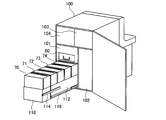
- FIG. 1 is a perspective view showing the appearance of an automated teller machine 100 equipped with a bill handling apparatus according to an embodiment of the present invention.
- the automated teller machine 100 is a device that is managed by a financial institution such as a bank and performs various transactions in accordance with the operation of a user (customer).
- the automated teller machine 100 includes a bill handling device 101, a coin handling device 102, a passbook handling device 103, a card statement slip handling device 104, and a customer operation unit 105.
- the cash automatic transaction apparatus 100 is provided with the main body control unit for controlling the power supply unit and the whole cash automatic transaction apparatus 100.
- the bill handling apparatus 101 is an apparatus for exchanging bills with a user.
- the bill handling apparatus 101 will be described in detail later.
- the coin handling device 102 exchanges coins with the user.
- the passbook handling apparatus 103 handles the passbook, and performs reading of a mark or the like described in the passbook, print processing, and the like according to the transaction.
- the card statement slip handling device 104 reads information recorded on a magnetic stripe card (so-called cash card), or issues a transaction statement slip recording the contents according to the transaction.
- the customer operation unit 105 is an interface with a user for performing information display for deposit and withdrawal transactions and operation input for deposit and withdrawal transactions.
- the bill handling apparatus 101 includes a tray 110 for storing the bill storage 70 and a tray 112 for storing the bill storages 71 to 74.
- the bill storages 71 to 74 are arranged in a line in the front-rear direction of the bill handling apparatus 101.
- the bill storages 72 to 74 are recycling bins for classifying and storing banknotes for circulation per denomination (hereinafter referred to as the bill storage 72 to 74).
- 74 are also respectively referred to as recycle bins 72 to 74).
- the bill storage 71 is used as a reject storage for storing reject bills unsuitable for transactions (hereinafter, the bill storage 71 is also referred to as a reject storage 71).
- the bill storage 70 is used as a loading and collecting bin for storing bills to be loaded into the recycling bins 72 to 74 and bills collected from the recycling bins 72 to 74 (hereinafter, the bill storage bin 70 is Also referred to as loading and recovery storage 70).
- the tray 110 and the tray 112 are connected by a rail 114, and the tray 110 can slide in the front-rear direction of the banknote handling apparatus 101 with respect to the tray 112. Further, the tray 112 and the casing of the bill handling apparatus 101 are connected by the rails 116, and the tray 112 can slide in the front-rear direction of the bill handling apparatus 101 with respect to the casing of the bill handling apparatus 101. It has become. By doing this, the tray 110 and the tray 112 are pulled out from the back side of the bill handling apparatus 101 or only the tray 110 is removed from the bill handling apparatus 101 while the tray 112 is left inside the bill handling apparatus 101. It can be pulled out.
- the transaction of the user of the automated teller machine 100 can The loading and recovering storage 70 can be attached and detached without stopping.
- the bill storage case 60 is also removable from the back side of the bill handling apparatus 101.
- the bill storage 60 is a reject storage for collecting bills forgotten by the bill depositing and dispensing unit and storing bills not used for deposit and withdrawal transactions. (Hereinafter, the bill storage 60 is also referred to as a reject storage 60).
- the bill handling apparatus 101 of the present embodiment arranges the plurality of bill storages and the bill transport path in a limited internal space, and suppresses the decline in bill transport efficiency and transport reliability. In order to use a part of these bill storages for multiple purposes, the configuration described below is provided.
- FIG. 4 is a side sectional view showing a schematic configuration of the bill handling apparatus.
- the bill handling apparatus 101 includes an upper unit 101u disposed at the upper portion and a safe portion 101c disposed at the lower portion.
- the upper unit 101 u generally, mechanisms necessary for exchanging bills with the user are collected.
- the upper unit 101 u is provided with a bill insertion and withdrawal safe 30, a bill identification unit 40, a temporary storage 50, a reject storage 60, and a control unit 80.
- the upper unit 101u is configured to be capable of bi-directionally transporting bills, as bidirectional transport paths 10a to 10f (hereinafter, the bidirectional transport paths 10a to 10f are collectively referred to as a first bidirectional transport path 10), And two bidirectional conveyance paths 20.
- the first bi-directional conveying path 10 and the second bi-directional conveying path 20 respectively rotate a plurality of conveying rollers indicated by circles in the drawing and those conveying rollers in both directions. (Not shown).
- one end of the bidirectional conveyance path 10a in the first bidirectional conveyance path 10 and one end of the bidirectional conveyance path 10f, ie, One end and the other end of the first bidirectional conveyance path 10 are arranged adjacent to each other.
- the second bidirectional conveyance path 20 is connected to any one of adjacent end portions of the bidirectional conveyance path 10 a and the bidirectional conveyance path 10 f. Whether to connect the bidirectional conveyance path 10a and the second bidirectional conveyance path 20 or to connect the bidirectional conveyance path 10f and the second bidirectional conveyance path 20 is switched by the gate 25g.
- the inside of the bill insertion and withdrawal safe 30 is divided by the partition plate 31 into a bill feeding unit 30i and a bill stacking unit 30o.
- the bill delivery unit 30i is connected to the first bidirectional conveyance path 10 via the conveyance path 30a (single direction conveyance path).
- the transport path 30a is connected so as to merge with the connection portion between the bidirectional transport path 10a and the bidirectional transport path 10b.
- bill delivery part 30i is provided with the delivery mechanism which draws out the bill inserted by the user to conveyance way 30a.
- the bill stacking unit 30o is connected to the first bidirectional conveyance path 10 via the conveyance path 30b (single direction conveyance path).
- the conveyance path 30b is connected so as to branch from the connection portion between the bidirectional conveyance path 10d and the bidirectional conveyance path 10e.
- bill accumulation part 30o is provided with the accumulation mechanism for accumulating the bill conveyed from conveyance way 30b.
- the bill stacking unit 30o is provided with a pressing plate 32 for moving the bills stacked in the bill stacking unit 30o in the direction of the partition plate 31.
- the bill validator 40 is disposed on the bidirectional conveyance path 10c. Then, the bill identifying unit 40 determines the denomination, authenticity, and each bill conveyed from the bidirectional conveyance path 10b to the bidirectional conveyance path 10c, or from the bidirectional conveyance path 10d to the bidirectional conveyance path 10c. It is identified whether or not it is a rejected banknote, and the identification result is output to the control unit 80. This identification can be performed, for example, using various information such as image data obtained by scanning a bill, unevenness on the surface of the bill, magnetic characteristics, optical characteristics against ultraviolet light and the like.
- the temporary storage 50 is connected to the first bidirectional transport path 10 via the transport path 50 a (bi-directional transport path).
- the conveyance path 50a is connected to the connection portion between the bidirectional conveyance path 10e and the bidirectional conveyance path 10f.
- the temporary storage 50 is provided with a stacking mechanism, and temporarily stores banknotes being transported.
- a gate 50g is disposed at the connection between the first bidirectional transport path 10 and the transport path 50a. By switching the gate 50g, it is possible to switch whether a bill is conveyed from the bidirectional conveyance path 10e to the conveyance path 50a or conveyed from the bidirectional conveyance path 10e to the bidirectional conveyance path 10f.
- the reject storage 60 is connected to the second bidirectional transport path 20 via the transport path 60 a (unidirectional transport path).
- the recycle storages 72 to 74, the reject storage 71, and the loading and collecting storage 70 are arranged in a line in the front-rear direction of the bill handling apparatus 101 and stored.
- the recycle storage 74 is connected to the bidirectional conveyance path 10 a via the conveyance path 74 a (two-way conveyance path). And the gate 74g is arrange
- the recycle storage 74 includes a mechanism for stacking and storing banknotes transported from the transport path 74a in the vertical direction, and a mechanism for delivering the stored banknotes to the transport path 74a.
- the recycle container 73 is connected to the bidirectional conveyance path 10 a via the conveyance path 73 a (two-way conveyance path). And the gate 73g is arrange
- the recycle storage 73 includes a mechanism for vertically accumulating and storing banknotes transported from the transport path 73a, and a mechanism for delivering the stored banknotes to the transport path 73a.
- the recycle storage 72 is connected to the bidirectional conveyance path 10 a via the conveyance path 72 a (two-way conveyance path). And the gate 72g is arrange
- the recycle storage 72 includes a mechanism for stacking and storing banknotes transported from the transport path 72a in the vertical direction, and a mechanism for delivering the stored banknotes to the transport path 72a.
- the reject storage 71 is connected to the second bidirectional transport path 20 via the transport path 71 a (unidirectional transport path). And the gate 71g is arrange
- the reject storage 71 is provided with a mechanism for stacking and storing banknotes transported from the transport path 71 a in the vertical direction.
- the loading and collecting bin 70 internally includes two bill storage units 80a and 80b and two transport paths 70a and 70b.
- the transport path 70a (bidirectional transport path) and the transport path 70b (unidirectional transport path) are respectively connected to the transport path 70c (bidirectional transport path) of the upper unit 101 u.
- the bill storage unit 80a is connected to the second bidirectional transport path 20 via the transport path 70a and the transport path 70c.
- the bill storage unit 80b is connected to the second bidirectional transport path 20 via the transport path 70b and the transport path 70c.
- a distribution mechanism unit which will be described later, is disposed at a connection portion between the conveyance paths 70a and 70b and the conveyance path 70c.
- the distribution mechanism By switching the distribution mechanism, conveyance is performed from the second bidirectional conveyance path 20 to the conveyance path 70c.
- the transfer destination of the received bill is switched.
- a gate 70g is disposed at a connection portion between the conveyance path 70c and the second bidirectional conveyance path 20, and switching the gate 70g allows the bidirectional conveyance path 10a or the bidirectional conveyance path 10f to a second position.
- the conveyance destination of the bill conveyed to the two-way conveyance path 20 is switched.
- a more specific configuration of the loading and recovery storage 70 will be described in detail later.
- the loading and collecting bin 70 corresponds to the "paper sheet storage bin" in the claims.
- the two bill accommodating units 80a and 80b correspond to the “paper sheet accommodating unit” in the claims.
- the two conveyance paths 70a and 70b correspond to the "inner conveyance path" in the claims.
- a plurality of sensors for detecting the passage of bills are disposed on the above-described conveyance paths, and the control unit 80 monitors the conveyance status of the bills on the conveyance paths.
- the control unit 80 is configured as a microcomputer having a CPU, memory, etc. inside, and according to a program prepared in advance based on the recognition result by the bill identification unit 40, the conveyance status of the bill on each conveyance path, etc. The operation of the handling device 101 is controlled.
- the control unit 80 corresponds to the “control unit” in the claims.
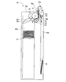
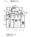
- FIG. 5 is an explanatory view showing a schematic configuration of the loading and recovery storage.
- recovery storage 70 is illustrated by FIG.
- the loading and collecting bin 70 has a substantially bowl-shaped outer shape, and a bill inlet / outlet portion 70p is formed on the upper side of the outer surface 70s.
- the bill inlet / outlet portion 70 p is an opening for taking in and out bills between the inside and the outside of the loading and collecting storage 70, and the transport paths 70 a and 70 b inside the loading and collecting storage 70 and the outside of the loading and collection storage 70
- the conveyance path 70c of A sorting mechanism 81 is disposed in the bill inlet / outlet portion 70p, and switching of the transport guide provided in the sorting mechanism 81 allows transport of the bill in the transport path 70c to the transport path 70a or to the transport path 70b. It is switched. Details of the distribution mechanism unit 81 will be described later.
- the conveyance path 70a can convey a bill in both directions between the bill inlet / outlet portion 70p and the bill storage portion 80a.
- the feed roller 41, the pickup roller 42, the gate roller 43, the brush roller 44, the pinch roller 45, and the stack guide 46 are disposed in the conveyance path 70a.
- the feed roller 41, the pickup roller 42, and the gate roller 43 are rotated by using a motor (not shown) as a power.
- the pickup roller 42 is disposed above the bill storage unit 80a, and feeds out the bills accumulated in the bill storage unit 80a one by one in a direction (also referred to as a "feed-out direction") to be fed out from the bill storage unit 80a.
- the gate roller 43 is disposed so that the outer periphery of the feed roller 41 and that of the feed roller 41 nest in the vicinity of the connection portion between the conveyance path 70a and the bill storage unit 80a, and stacks the bills in the bill storage unit 80a ( (Also referred to as “)”, and does not rotate in the feeding direction.
- the brush roller 44 is disposed coaxially with the gate roller 43, and is configured to strike down the banknotes accumulated in the banknote storage unit 80a by the radially arranged elastic members.
- the pinch roller 45 contacts the feed roller 41 and rotates as the feed roller 41 rotates.
- the stack guide 46 is a member that is disposed above the bill storage unit 80a and is in contact with a bill carried into the bill storage unit 80a from the conveyance path 70a and guides the bill to the lower side of the bill storage unit 80a.
- the stack guide 46 has a substantially plate-like shape, and is configured to be vertically swingable about a swinging axis provided above the bill storage portion 80a.
- the stack guide 46 retracts upward at the time of delivery and protrudes downward at the time of accumulation.
- the number of stack guides 46 can be set arbitrarily, and the shape may be any shape such as, for example, a substantially plate shape.
- the bill storage unit 80a is a space for stacking and stacking the bills in the vertical direction, and internally includes a lift plate 47 as a floor plate for supporting the deposited bills.
- the lift plate 47 has a configuration that can be lifted and lowered by a lift mechanism (not shown).
- the side wall inside the bill storage unit 80a is configured to be adjustable according to the shape of the bill to be stored.
- the transport path 70b can transport the bills of the bill inlet / outlet portion 70p to the bill storage portion 80b.
- the transport path 70b is a unidirectional transport path which is driven only in the direction to accumulate the bills in the bill storage portion 80b and is not driven in the direction in which the bills are fed out from the bill storage portion 80b.
- Pinch rollers 51 and 52 and a brush roller 53 are disposed in the conveyance path 70b.
- the pinch roller 51 is configured to rotate only in the direction in which the bills are accumulated in the bill storage portion 80b and not to rotate in the feeding direction.
- the brush roller 53 is configured coaxially with the pinch roller 51, and is configured to strike down the bills accumulated in the bill storage unit 80b by the radially arranged elastic members.
- the pinch roller 52 contacts the pinch roller 51 and transports the bills in the stacking direction.
- bill storage part 80b is a space part for accumulating a bill, and it is not necessary to draw out the accumulated bill, there is no restriction in particular about the posture of the bill stored, and the shape of a space part. Therefore, it can be set as the arbitrary shape according to the shape of the loading collection
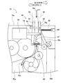
- FIG. 6 is an explanatory view showing a schematic configuration of the distribution mechanism unit.
- the distribution mechanism unit 81 includes a pair of conveyance guides 82 and 83, a power transmission member 84, springs 85 and 86, a coupling member 88, and a solenoid 89.
- the distribution mechanism unit 81 is arranged side by side so as to face the pair of apparatus-side conveyance guides 92 and 93 that constitute the conveyance path 70 c of the upper unit 101 u.
- the pair of transport guides 82 and 83 are members for distributing the bills transported to the bill inlet / outlet portion 70p by the transport path 70c to either the bill storage portion 80a or the bill storage portion 80b. It is fixed so as to be swingable in the left direction LD and the right direction RD about the moving shaft 87.
- one conveyance guide 82 disposed between the conveyance path 70a and the conveyance path 70b is referred to as a first conveyance guide 82, and conveyance is performed with the first conveyance guide 82.
- the other conveyance guide 83 opposed via the passage 70 a is called a second conveyance guide 83.
- the apparatus side conveyance guide 92 disposed above the first conveyance guide 82 is called a first apparatus side conveyance guide 92
- the apparatus-side conveyance guide 93 disposed above the second conveyance guide 83 is referred to as a second apparatus-side conveyance guide 93.
- the first conveyance guide 82 and the first apparatus side conveyance guide 92 are linearly arranged, and the second conveyance guide 83 and the second apparatus side conveyance guide 93 are linearly arranged.
- the state of being linearly arranged means a state in which the two guides are functionally continuous, and the two guides do not necessarily have to be in physical contact.
- the end portions of the two guides are aligned, and when the guides are connected, one transport path is formed.
- the state of being linearly arranged is not limited to the state of being linearly arranged, but includes the state of being curvilinearly arranged or the state of being partially bent and arranged. In FIG.
- the bills transported to the bill inlet / outlet portion 70p by the transport path 70c are distributed to the bill storage portion 80a via the transport path 70a.
- the state of the 1st conveyance guide 82 and the 2nd conveyance guide 83 is shown by FIG. 7 mentioned later.
- the specific shapes of the first conveyance guide 82, the second conveyance guide 83, the first apparatus side conveyance guide 92, and the second apparatus side conveyance guide 93 will be described later.
- the power transmission member 84 is a rod-like member whose one end is connected to the upper side of the first conveyance guide 82 and the other end is connected to the solenoid 89, and the power of the solenoid 89 is carried by the first conveyance. It is transmitted to the guide 82.
- One end of the spring 85 is connected to the lower side of the first conveyance guide 82, and the other end is connected to the lower side of the second conveyance guide 83, and the upper side of the first conveyance guide 82 is the left. When it swings in the direction LD, it stretches and pulls the second transport guide 83, and swings the upper side of the second transport guide 83 in the same left direction LD as the first transport guide 82.
- the spring 86 has one end connected to the upper side of the first transport guide 82 and the other end connected to the portion 86 f fixed in the loading and recovery storage 70, and the upper side of the first transport guide 82 is When it swings in the left direction LD, it extends to pull the upper side of the first conveyance guide 82 in the right direction RD.
- the connecting member 88 has a length such that one end is connected to the upper side of the first conveyance guide 82 and the other end is in contact with the back side not facing the first conveyance guide 82 of the second conveyance guide 83. It is an elongated member, and when the upper side of the first transport guide 82 swings in the right direction RD, the upper side of the second transport guide 83 swings in the right direction RD.
- the solenoid 89 moves the power transmission member 84 in the left direction LD and the right direction RD in response to the electrical signal from the control unit 80.
- FIG. 6 shows a state in which the solenoid 89 is in the OFF state, and the power transmission member 84 extends in the right direction RD.
- the rocking directions of the first conveyance guide 82 and the second conveyance guide 83 mean the rocking directions on the upper side thereof.
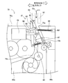
- FIG. 7 is an explanatory view exemplifying a state in which the conveyance guide is swung in the left direction LD.
- FIG. 7 shows a state in which the first conveyance guide 82 and the second apparatus side conveyance guide 93 are linearly arranged.
- the solenoid 89 When the solenoid 89 is turned on in response to the electric signal from the control unit 80, the solenoid 89 moves the power transmission member 84 in the left direction LD.
- the power transmission member 84 moves in the left direction LD, the first conveyance guide 82 swings in the left direction LD about the swing shaft 87.
- the second conveyance guide 83 is pulled by the spring 85, and swings in the left direction LD about the swing shaft 87 in the same manner as the first conveyance guide 82.
- the first conveyance guide 82 pivoted in the left direction LD is linearly aligned with the second apparatus conveyance guide 93 as shown in FIG.
- the first transport guide 82 is linearly aligned with the second apparatus-side transport guide 93, the bills transported to the bill inlet / outlet portion 70p by the transport path 70c are transferred to the bill storage portion 80b via the transport path 70b. It is distributed.
- FIG. 8 is an explanatory view for explaining a schematic configuration of the conveyance guide and the apparatus side conveyance guide.
- the first conveyance guide 82 and the first apparatus side conveyance guide 92 are linearly arranged, and the second conveyance guide 83 and the second apparatus side conveyance guide 93 are lines. It is shown in a line.
- FIG. 9 is an explanatory view for explaining a state in which the conveyance guide is viewed from above when the first conveyance guide is linearly aligned with the first apparatus-side conveyance guide.
- the comb teeth of the conveyance guides 82 and 83 are shown by a cross hatch, and the comb teeth of the apparatus side conveyance guides 92 and 93 are shown by a broken line.
- the first conveyance guide 82 has a plurality of comb teeth 82t in the direction along the swing axis 87 at the end opposite to the first apparatus-side conveyance guide 92. It has a comb-tooth-like portion 82c arranged side by side.
- a plurality of comb teeth 92t extending downward are arranged side by side.
- the second conveyance guide 83 is a comb-shaped portion 83 c in which a plurality of comb teeth 83 t are arranged in a direction along the swing shaft 87 at an end of the side facing the second apparatus-side conveyance guide 93. Is equipped.
- a plurality of comb teeth 93t extending downward are arranged side by side.
- the comb teeth 82c of the first conveyance guide 82 and the comb teeth 83c of the second conveyance guide 83 move in the swing direction of the first conveyance guide 82 and the second conveyance guide 83 (the left direction LD and the second conveyance guide 83).
- the comb teeth In the right direction RD), the comb teeth (the comb teeth 82t and the comb teeth 83t) are arranged to face each other.
- each tip end of the comb teeth 82t, 83t, 92t, 93t described above is chamfered or the like in order to suppress the catching of the bill at the connection portion between the transport guide and the apparatus side transport guide. Processing is performed to suppress the generation of the corner.
- FIG. 10 is an explanatory view for explaining a state where the transport guide is viewed from above when the first transport guide is linearly aligned with the second apparatus-side transport guide.
- the comb teeth of the transport guides 82 and 83 are indicated by a cross hatch, and the comb teeth of the apparatus-side transport guides 92 and 93 are indicated by a broken line.
- the first transfer guide 82 swings in the left direction LD by the comb teeth 82t in the state shown in FIG. 9, the comb teeth 93t and the comb teeth of the second apparatus side transfer guide 93 are It enters between 93t and aligns with the second apparatus side conveyance guide 93 in a line.
- the comb teeth 83t enter between the comb teeth 93t and the comb teeth 93t of the second apparatus side conveyance guide 93, and the second As shown in FIG. 10, the comb teeth 83t swing in the left direction LD from the state of being linearly arranged 93, and the state of being linearly arranged with the second apparatus side conveyance guide 93 is released.
- FIG. 11 is an explanatory view showing the operation of the bill handling device at the time of the loading process.
- the loading process is a process for loading the bills stored in the loading and collecting bin 70 so as to be loaded into the recycling bins 72 to 74 into the recycling bins 72 to 74.
- the control unit 80 controls the gate 25g to connect the second bidirectional transport path 20 and the bidirectional transport path 10f.
- the distribution mechanism unit 81 is in the state shown in FIG.
- the control unit 80 controls the transport rollers and the like provided in the respective transport paths to feed the banknotes stored in the bill storage portion 80a of the loading and collecting bin 70 one by one to the transport path 70a, as shown in FIG.
- the conveyance path 70c, the second bidirectional conveyance path 20, the bidirectional conveyance path 10f, the bidirectional conveyance path 10e, the bidirectional conveyance path 10d, and the bidirectional conveyance path 10c are sequentially conveyed.
- control unit 80 conveys the bill identified by bill identification part 40 in order of bidirectional conveyance way 10b and bidirectional conveyance way 10a.
- the control unit 80 controls the gates 72g, 73g, and 74g based on the identification result by the bill identification unit 40, and distributes the bills conveyed to the bidirectional conveyance path 10a to the conveyance paths 72a to 74a. Classify by denomination into ⁇ 74 and load.
- control unit 80 performs operation control demonstrated below.
- FIG. 12 is an explanatory view showing the operation of the banknote handling apparatus when a rejected banknote is found during the loading process.
- the control unit 80 temporarily stops the delivery of the bill from the loading and collecting bin 70 to the transport path 70a. At this time, conveyance of the bill in each conveyance way is continued. Thereafter, when all the banknotes present on the transport path 70a, the transport path 70c, and the second bidirectional transport path 20 are transported to the bi-directional transport path 10f and thereafter, the control unit 80 sets the gate 25g.
- the control unit 80 switches the distribution mechanism unit 81 to the state of FIG. 7 and stores the rejected banknotes from the transport path 70b into the banknote storage unit 80b.
- control unit 80 stores each bill conveyed subsequent to the rejected bill in the recycle storage 72 to 74 or the bill storage unit 80b of the loading collection store 70 based on the identification result by the bill identification unit 40. Do. Thereafter, the control unit 80 returns the operation of the banknote handling apparatus 101 to the operation shown in FIG. 11 and continues the loading process.
- the control unit 80 ends the loading process when all the bills in the bill storage unit 80a of the loading and collecting bin 70 or a predetermined number of bills determined in advance are loaded into the recycle bins 72 to 74.
- the sorting mechanism unit 81 for sorting the conveyance destinations of the bills is formed in the bill inlet and outlet part 70p, so that the convenience of the paper sheets storage bin such as the loading and collecting bin 70 can be obtained. It is possible to improve the quality. Specifically, since the loading and recovering storage 70 can distribute the bills to the two internal storage spaces (the bill accommodating sections 80a and 80b) by the distribution mechanism unit 81, the loading of the bills, the recovery of the rejected bills, and the like are performed. It can be done by one banknote storage. Therefore, it is not necessary to separately install a reject storage for collecting rejected banknotes determined to be unsuitable for loading at the time of loading, and it is possible to increase the number of recycle storages that can be stored in the banknote handling apparatus 101 when loading banknotes.
- the opening part for taking in and out of a bill between two storage space (bill storage part 80a, 80b) and the exterior is one place of the bill inlet-outlet part 70p of the loading collection
- the distribution mechanism unit 81 is formed in the bill inlet / outlet part 70p, most of the main body of the loading and collecting bin 70 can be used for bill storage space. That is, the bill accommodating units 80a and 80b need to be installed below the distributing mechanism unit 81, but the distributing mechanism unit 81 is disposed at the uppermost position of the loading and collecting case 70. The majority can be allocated to the bill accommodating portions 80a and 80b.
- the conveyance guides (the first conveyance guide 82 and the second conveyance guide 83) are disposed on both sides of the conveyance path in the conveyance path 70a which is a bidirectional conveyance path. There is. Thereby, it can be suppressed that the bill drawn out from the bill storage unit 80a is caught at the connection portion between the conveyance path 70a and the conveyance path 70c.
- a conveyance guide (first conveyance guide 82) is installed on only one side of the conveyance path 70b which is a single-direction conveyance path.
- the transport path 70b is not configured to feed the bills from the bill storage portion 80b, and therefore, it is not necessary to consider the catching of the bill at the connection between the transport path 70b and the transport path 70c in the feed direction.
- the configuration of the distribution mechanism unit 81 can be simplified.
- FIG. 13 is an explanatory view showing a schematic configuration of the loading and collecting bin in the second embodiment.
- FIG. 13 corresponds to FIG. 5 of the first embodiment.
- the loading and recovery storage 70 of the first embodiment includes one bidirectional transport path (transporting path 70a) and one unidirectional transport path (transporting path 70b).
- the loading and recovery storage 70x of the second embodiment Has two bi-directional transport paths.
- the configuration of the bill handling apparatus 101 to which the loading and recovery bin 70x of the second embodiment can be applied and the configuration of the automated teller machine 100 are the same as those of the first embodiment, and thus the description thereof will be omitted.
- the loading and collecting bin 70x internally includes two transport paths 70a and 70bx and two bill storage units 80a and 80bx.
- the configurations of the transport path 70a and the bill storage portion 80a are the same as those of the transport path 70a and the bill storage portion 80a of the first embodiment, and thus the description thereof will be omitted.
- the transport path 70bx includes the feed roller 41b, the pick-up roller 42b, the gate roller 43b, the brush roller 44b, the pinch roller 45b, and the stack guide 46b in the same manner as the transport path 70a. It is configured to be transportable.
- the bill storage unit 80bx includes the elevating plate 47b as in the case of the bill storage unit 80a, and stacks bills by stacking the bills in the vertical direction.
- the distribution mechanism unit 81x includes a first conveyance guide 82 disposed between the conveyance path 70a and the conveyance path 70bx, and a second conveyance guide 83 facing the first conveyance guide 82 via the conveyance path 70a. And a third conveyance guide 83x facing the first conveyance guide 82 via the conveyance path 70bx.
- the configurations of the first conveyance guide 82 and the second conveyance guide 83 are the same as those of the first conveyance guide 82 and the second conveyance guide 83 in the first embodiment, and thus the description thereof will be omitted.
- the third conveyance guide 83x is disposed below the first apparatus conveyance guide 92.
- the first conveyance guide 82 and the second apparatus side conveyance guide 93 are linearly arranged, and the third conveyance guide 83x and the first apparatus side conveyance guide 92 are linearly arranged. It is shown.
- the bills transported to the bill inlet / outlet portion 70p by the transport path 70c are distributed to the bill storage portion 80bx via the transport path 70bx.
- the conveyance direction of the bill by the conveyance path 70bx it is possible to feed the bill of the bill storage portion 80bx to the conveyance path 70c through the conveyance path 70bx.
- the third transport guide 83x is also swung in the right direction RD, and the first transport guide 82 is on the first device side. Line up with the conveyance guide 92 in a line.
- the first transport guide 82 is linearly aligned with the first apparatus-side transport guide 92, the bills transported to the bill inlet / outlet portion 70p by the transport path 70c are transferred to the bill storage portion 80a via the transport path 70a. It is distributed.
- the loading and recovery storage 70 may be configured to include two bidirectional transport paths. Even in this case, the convenience of the paper sheet storage can be improved. For example, by storing bills of different denominations in the bill storage unit 80a and the bill storage unit 80b, the number of denominations that can be handled by the bill handling apparatus 101 can be increased.
- the loading and recovery storage 70 of the first embodiment includes a bidirectional transport path (transporting path 70a) and a unidirectional transport path (transporting path 70b).
- the loading and recovery storage 70x of the second embodiment includes two bidirectional transports. Although it has been described that the paths (conveying paths 70a and 70bx) are provided, the conveying direction of the conveying path provided in the loading and collecting bin can be arbitrarily set in addition to the above. For example, both of the transport paths of the loading and recovery storage may be unidirectional transport paths, or only the transport path 70a may be a unidirectional transport path.
- Modification 2 Although the loading and recovery storage 70 of the present embodiment has been described as including the second transport guide 83, the loading and recovery storage 70 may not include the second transport guide 83. That is, also in the bidirectional conveyance path (the conveyance path 70a), only one conveyance guide may be disposed at the connection with the conveyance path 70c. Even in this case, if the distribution mechanism unit 81 is formed in the bill inlet / outlet portion 70p, the convenience of the loading and collecting bin 70 can be improved.
- the loading and collecting bin 70 of the present embodiment has been described as including two bill storage units and two transport paths, the loading and recovery bin 70 includes three or more bill storage units and transport passes. It is also good.
- the loading and collecting bin 70 may include two or more distribution mechanism units 81.
- the loading and collecting bin may be configured to distribute the bills to the three bill accommodating parts by providing the second distribution mechanism part in the middle of the transport path 70a.
- the loading and collecting bin may have two bill inlet / outlet portions 70p on the outer surface 70s, and the distribution mechanism portion 81 may be disposed in each of them.
- the end sides of the conveyance guides 82 and 83 and the apparatus side conveyance guides 92 and 93 may simply be in contact with or close to each other, or the conveyance guides 82 and 83 and the apparatus side conveyance guides 92 and 93 may be respectively It may have a configuration in which notches in the thickness direction are cut out and the notches come in contact with each other.
- Modification 5 In the present embodiment, only the loading process has been described as the operation control of the bill handling apparatus, but the bill handling apparatus 101 performs the deposit process, the withdrawal process, the recovery process, the counterfeit note recovery process, the forgotten recovery process, etc. It can be done.
- the deposited banknotes can be stored in the banknote storage unit 80a, and in the dispensing process, the banknotes can be drawn out from the banknote storage unit 80a.
- the three recycling bins 72 to 74 are connected to the bi-directional transport path 10a, but the number of recycle bins connected to the bi-directional transport path 10a It can be set arbitrarily according to the type. Further, at least one of the recycle boxes 72 to 74 and the reject box 71 may have the same structure as that of the loading and collecting box 70 of the present invention.
- the bill handling apparatus 101 is provided in the automated teller machine 100.
- the bill handling apparatus 101 may be, for example, a money changer, a bill depositing / dispensing machine used by bankers in a row, or automatic ticketing. You may be equipped with a machine etc.
- Modification 10 The present invention can be realized in various forms other than the above, and for example, a bill collection device, a recycle container, a reject container, a bill handling apparatus provided with these, a bill handling method, and its handling method It can be realized in the form of a computer program or the like to be realized. Further, the paper sheet storage, the paper sheet handling apparatus and the automated teller machine according to the present invention can be applied in combination with other members as appropriate.
Landscapes
- Engineering & Computer Science (AREA)
- Mechanical Engineering (AREA)
- Physics & Mathematics (AREA)
- General Physics & Mathematics (AREA)
- Separation, Sorting, Adjustment, Or Bending Of Sheets To Be Conveyed (AREA)
- Pile Receivers (AREA)
Abstract
Description
紙葉類取扱装置に搭載され、紙葉類の集積および繰出しをおこなう紙葉類収納庫であって、
前記紙葉類収納庫の内部において紙葉類を収容する複数の紙葉類収容部と、
前記紙葉類収納庫の外表面部に形成され、前記紙葉類収納庫の内部と外部との間の紙葉類の出し入れをおこなうための紙葉類出入口部と、
前記紙葉類出入口部に形成され、前記紙葉類収納庫の外部から前記紙葉類出入口部に搬送された搬送紙葉類を前記複数の紙葉類収容部のうちのいずれか1つの紙葉類収容部に振り分ける振分け機構部と、を備える紙葉類収納庫。
適用例1に記載の紙葉類収納庫において、
前記振分け機構部は、前記紙葉類収納庫が前記紙葉類取扱装置に搭載されたときに、前記紙葉類取扱装置において前記搬送紙葉類が搬送される搬送路を形成する装置側搬送ガイドと並んで配置される、紙葉類収納庫。
適用例2に記載の紙葉類収納庫において、
前記紙幣収納庫は、2つの紙葉類収容部を備え、
前記振分け機構部は、揺動によって、一対の前記装置側搬送ガイドのいずれとも線状に並ぶことのできる第1の搬送ガイドを備え、前記第1の搬送ガイドを一方の前記装置側搬送ガイドと線状に並んだ状態から他方の前記装置側搬送ガイドと線状に並んだ状態に切り換えることによって、前記搬送紙葉類の搬送先を一方の前記紙葉類収容部から他方の紙葉類収容部に切り換える、紙葉類収納庫。
適用例3に記載の紙葉類収納庫において、
前記第1の搬送ガイドは、各前記紙葉類収容部と前記紙葉類出入口部との間にそれぞれ構成される2つの内部搬送路の間に配置され、前記一方の装置側搬送ガイドと線状に並んでいるときに、一方の前記内部搬送路の一部を構成し、前記他方の装置側搬送ガイドと線状に並んでいるときに、他方の前記内部搬送路の一部を構成する、紙葉類収納庫。
適用例4に記載の紙葉類収納庫において、
前記振分け機構部は、前記第1の搬送ガイドと対向する位置に第2の搬送ガイドを備え、
第2の搬送ガイドは、前記第1の搬送ガイドが前記一方の装置側搬送ガイドと線状に並んでいるときに、前記他方の装置側搬送ガイドと線状に並び、前記第1の搬送ガイドが揺動して前記他方の装置側搬送ガイドと線状に並ぶときに、前記第1の搬送ガイドと同じ方向に揺動して前記他方の装置側搬送ガイドと線状に並んだ状態を解除する、紙葉類収納庫。
適用例5に記載の紙葉類収納庫において、
前記第1の搬送ガイドが前記一方の装置側搬送ガイドと線状に並び、前記第2の搬送ガイドが前記他方の装置側搬送ガイドと線状に並んでいるときに、前記紙葉類取扱装置の搬送路と連通する一方の前記内部搬送路は、紙葉類を双方向に搬送可能に構成され、
前記第1の搬送ガイドが前記他方の装置側搬送ガイドと線状に並んでいるときに、前記紙葉類取扱装置の搬送路と連通する他方の前記内部搬送路は、前記紙葉類出入口部から前記紙葉類収容部に向かう方向にのみ紙葉類を搬送可能に構成されている、紙葉類収納庫。
適用例5または適用例6に記載の紙葉類収納庫において、
前記第1の搬送ガイドおよび前記第2の搬送ガイドは、複数の櫛歯が並んで構成される櫛歯状部を備え、前記装置側搬送ガイドと線状に並んだときに、前記櫛歯が前記装置側搬送ガイドの備える複数の櫛歯の間に入る、紙葉類収納庫。
適用例3ないし適用例7のいずれかに記載の紙葉類収納庫において、
前記振分け機構部は、前記第1の搬送ガイドを前記一方の装置側搬送ガイドと線状に並んでいる状態から前記他方の装置側搬送ガイドと線状に並んでいる状態に切り換えるための駆動部を備えている、紙葉類収納庫。
適用例1ないし適用例8のいずれかに記載の紙葉類収納庫において、
前記紙葉類収納庫は、紙葉類取扱装置が備えるトレイに脱着可能に搭載される、紙葉類収納庫。
紙葉類取扱装置であって、
適用例1ないし適用例9のいずれかに記載の紙葉類収納庫と、
前記紙葉類収納庫を脱着可能に搭載するためのトレイと、
前記紙葉類収納庫の前記紙葉類出入口部に紙葉類を搬送するための搬送路を形成する装置側搬送ガイドと、を備える紙葉類取扱装置。
現金自動取引装置であって、
適用例10に記載の紙葉類取扱装置と、
前記振分け機構部を制御するための制御部と、を備える現金自動取引装置。
A1.現金自動取引装置の構成:
図1は、本発明の一実施例としての紙幣取扱装置を搭載した現金自動取引装置100の外観を示す斜視図である。この現金自動取引装置100は、銀行などの金融機関によって管理され、利用者(顧客)の操作に応じて各種取引を行うための装置である。現金自動取引装置100は、紙幣取扱装置101と、硬貨取扱装置102と、通帳取扱装置103、カード明細票取扱装置104と、顧客操作部105と、を備えている。また、図示は省略しているが、現金自動取引装置100は、電源ユニットや、現金自動取引装置100の全体を制御するための本体制御ユニットを備えている。
本実施例の紙幣取扱装置101は、上述した複数の紙幣収納庫、および、紙幣の搬送路を、限られた内部スペースに配置し、紙幣の搬送効率や搬送信頼性の低下を抑制しつつ、これらの紙幣収納庫の一部を多目的に利用可能とするために、以下に説明する構成を備えている。
図5は、装填回収庫の概略構成を示す説明図である。図5には、装填回収庫70の側断面が例示されている。装填回収庫70は、略筺形状の外形を備え、外表面70sの上方側には、紙幣出入口部70pが形成されている。紙幣出入口部70pは、装填回収庫70の内部と外部との間で紙幣の出し入れを行うための開口部であり、装填回収庫70の内部の搬送路70a、70bと、装填回収庫70の外部の搬送路70cとが接続されている。紙幣出入口部70pには、振分け機構部81が配置され、この振分け機構部81が備える搬送ガイドの切り換えによって、搬送路70cの紙幣を搬送路70aに搬送するか、搬送路70bに搬送するかが切り換えられる。振分け機構部81の詳細については後述する。
図6は、振分け機構部の概略構成を示す説明図である。振分け機構部81は、一対の搬送ガイド82、83と、動力伝達部材84と、バネ85、86と、連結部材88と、ソレノイド89と、を備えている。振分け機構部81は、上部ユニット101uの搬送路70cを構成する一対の装置側搬送ガイド92、93と対向するように並んで配置されている。一対の搬送ガイド82、83は、搬送路70cによって紙幣出入口部70pに搬送された紙幣を紙幣収容部80aか紙幣収容部80bのいずれか一方の搬送先に振り分けるための部材であり、それぞれ、揺動軸87を中心にして左方向LDおよび右方向RDに揺動可能に固定されている。
A5-1.装填処理:
図11は、装填処理時の紙幣取扱装置の動作を示す説明図である。装填処理は、リサイクル庫72~74に装填すべく装填回収庫70に収納された紙幣をリサイクル庫72~74に装填する処理である。本実施例では、装填回収庫70には、複数金種の紙幣が収納されているものとする。
図13は、第2実施例における装填回収庫の概略構成を示す説明図である。図13は、第1実施例の図5と対応している。第1実施例の装填回収庫70は、1つの双方向搬送路(搬送路70a)と、1つの単方向搬送路(搬送路70b)を備えているが、第2実施例の装填回収庫70xは、2つの双方向搬送路を備えている。第2実施例の装填回収庫70xを適用可能な紙幣取扱装置101の構成や、現金自動取引装置100の構成については、第1実施例と同様のため説明を省略する。
本発明は上記の実施例や実施形態に限られるものではなく、その要旨を逸脱しない範囲において種々の態様において実施することが可能であり、例えば次のような変形も可能である。
第1実施例の装填回収庫70は、双方向搬送路(搬送路70a)と、単方向搬送路(搬送路70b)を備え、第2実施例の装填回収庫70xは、2つの双方向搬送路(搬送路70a、70bx)を備えているものとして説明したが、装填回収庫が備える搬送路の搬送方向は上記以外にも任意に設定することができる。例えば、装填回収庫の搬送路は、2つとも単方向搬送路であってもよいし、搬送路70aのみが単方向搬送路であってもよい。
本実施例の装填回収庫70は、第2の搬送ガイド83を備えているものとして説明したが、装填回収庫70は、第2の搬送ガイド83を備えていなくてもよい。すなわち、双方向搬送路(搬送路70a)においても、搬送路70cとの接続部に1つの搬送ガイドのみが配置されていてもよい。この場合であっても、振分け機構部81が紙幣出入口部70pに形成されていれば、装填回収庫70の利便性の向上を図ることができる。
本実施例の装填回収庫70は、2つの紙幣収容部と2つの搬送路を備えているものとして説明したが、装填回収庫70は、3つ以上の紙幣収容部や搬送路を備えていてもよい。また、装填回収庫70は、2つ以上の振分け機構部81を備えていてもよい。例えば、装填回収庫は、搬送路70aの途中に第2の振分け機構部を備えることによって、3つの紙幣収容部に紙幣を振り分ける構成としてもよい。また、装填回収庫は、外表面70sに2つの紙幣出入口部70pを備え、それぞれに振分け機構部81が配置されていてもよい。
本実施例の搬送ガイド82、83は、図8に示すように、櫛歯状部82c、83cを備えているものとして説明したが、搬送ガイド82、83は、櫛歯状部82c、83cを備えていなくてもよい。すなわち、搬送ガイド82、83の先端部と装置側搬送ガイド92、93の先端部は、櫛歯同士が噛み合う構成に限定されず、任意の形態とすることができる。例えば、搬送ガイド82、83と装置側搬送ガイド92、93の互いの端辺が単に接触または近接する構成であってもよいし、搬送ガイド82、83と装置側搬送ガイド92、93が、それぞれ厚み方向に切り欠かれた切り欠き部を有し、その切り欠き部が互いに接触する構成であってもよい。
本実施例では、紙幣取扱装置の動作制御として、装填処理についてのみ説明したが、紙幣取扱装置101は、入金処理、出金処理、回収処理、偽券回収処理、および、取り忘れ回収処理などをおこなうことができる。例えば、入金処理において、入金された紙幣が、紙幣収容部80aに収納される構成とすることができるし、出金処理において、紙幣収容部80aから紙幣を繰り出す構成とすることができる。
本実施例の紙幣取扱装置101は、双方向搬送路10aに3つのリサイクル庫72~74が接続されるものとしたが、双方向搬送路10aに接続されるリサイクル庫の数は、取り扱う紙幣の種類に応じて、任意に設定可能である。また、リサイクル庫72~74やリジェクト庫71の少なくとも1つの構成を本願の装填回収庫70の構成と同様の構成としてもよい。
上記実施例では、紙幣取扱装置101は、リジェクト庫60を備えているものとして説明したが、装填回収庫70の紙幣収容部80bをリジェクト庫として利用すれば、リジェクト庫60を備えていなくてもよい。
上記実施例では、紙幣取扱装置101のリジェクト庫71は、第2の双方向搬送路20に接続されるものとして説明したが、紙幣取扱装置101は、リジェクト庫71を双方向搬送路10aに接続する構成であってもよい。
上記実施例では、紙幣取扱装置101は現金自動取引装置100に備えられるものとしたが、紙幣取扱装置101は、例えば、両替機や、銀行員が行内で使用する紙幣入出金機や、自動発券機等に備えられてもよい。
なお、本発明は、上記以外の種々の形態で実現することが可能であり、例えば、充填回収庫、リサイクル庫、リジェクト庫、これらを備える紙幣取扱装置、および、紙幣取扱方法、その取扱方法を実現するためのコンピュータープログラム等の形態で実現することができる。また、本発明に係る紙葉類収納庫、紙葉類取扱装置および現金自動取引装置は、適宜、他の部材と組み合わせて適用することができる。
20…第2の双方向搬送路
30…紙幣入出金庫
31…仕切板
32…押圧板
40…紙幣識別部
41…フィードローラ
42…ピックアップローラ
43…ゲートローラ
44…ブラシローラ
45…ピンチローラ
46…スタックガイド
47…昇降板
50…一時保管庫
51…ピンチローラ
52…ピンチローラ
53…ブラシローラ
60…紙幣収納庫
60…リジェクト庫
70…装填回収庫
70a、70b、70c…搬送路
70p…紙幣出入口部
70s…外表面
71…リジェクト庫
72、73、74…リサイクル庫
80…制御ユニット
80a、80b…紙幣収容部
81…振分け機構部
82…第1の搬送ガイド
82t…櫛歯
83…第2の搬送ガイド
83t…櫛歯
84…動力伝達部材
85、86…バネ
87…揺動軸
88…連結部材
89…ソレノイド
92…第1の装置側搬送ガイド
92t…櫛歯
93…第2の装置側搬送ガイド
93t…櫛歯
100…現金自動取引装置
101…紙幣取扱装置
102…硬貨取扱装置
103…通帳取扱装置
104…カード明細票取扱装置
105…顧客操作部
110、112…トレイ
114、116…レール
Claims (11)
- 紙葉類取扱装置に搭載され、紙葉類の集積および繰出しをおこなう紙葉類収納庫であって、
前記紙葉類収納庫の内部において紙葉類を収容する複数の紙葉類収容部と、
前記紙葉類収納庫の外表面部に形成され、前記紙葉類収納庫の内部と外部との間の紙葉類の出し入れをおこなうための紙葉類出入口部と、
前記紙葉類出入口部に形成され、前記紙葉類収納庫の外部から前記紙葉類出入口部に搬送された搬送紙葉類を前記複数の紙葉類収容部のうちのいずれか1つの紙葉類収容部に振り分ける振分け機構部と、を備える紙葉類収納庫。 - 請求項1に記載の紙葉類収納庫において、
前記振分け機構部は、前記紙葉類収納庫が前記紙葉類取扱装置に搭載されたときに、前記紙葉類取扱装置において前記搬送紙葉類が搬送される搬送路を形成する装置側搬送ガイドと並んで配置される、紙葉類収納庫。 - 請求項2に記載の紙葉類収納庫において、
前記紙幣収納庫は、2つの紙葉類収容部を備え、
前記振分け機構部は、揺動によって、一対の前記装置側搬送ガイドのいずれとも線状に並ぶことのできる第1の搬送ガイドを備え、前記第1の搬送ガイドを一方の前記装置側搬送ガイドと線状に並んだ状態から他方の前記装置側搬送ガイドと線状に並んだ状態に切り換えることによって、前記搬送紙葉類の搬送先を一方の前記紙葉類収容部から他方の紙葉類収容部に切り換える、紙葉類収納庫。 - 請求項3に記載の紙葉類収納庫において、
前記第1の搬送ガイドは、各前記紙葉類収容部と前記紙葉類出入口部との間にそれぞれ構成される2つの内部搬送路の間に配置され、前記一方の装置側搬送ガイドと線状に並んでいるときに、一方の前記内部搬送路の一部を構成し、前記他方の装置側搬送ガイドと線状に並んでいるときに、他方の前記内部搬送路の一部を構成する、紙葉類収納庫。 - 請求項4に記載の紙葉類収納庫において、
前記振分け機構部は、前記第1の搬送ガイドと対向する位置に第2の搬送ガイドを備え、
第2の搬送ガイドは、前記第1の搬送ガイドが前記一方の装置側搬送ガイドと線状に並んでいるときに、前記他方の装置側搬送ガイドと線状に並び、前記第1の搬送ガイドが揺動して前記他方の装置側搬送ガイドと線状に並ぶときに、前記第1の搬送ガイドと同じ方向に揺動して前記他方の装置側搬送ガイドと線状に並んだ状態を解除する、紙葉類収納庫。 - 請求項5に記載の紙葉類収納庫において、
前記第1の搬送ガイドが前記一方の装置側搬送ガイドと線状に並び、前記第2の搬送ガイドが前記他方の装置側搬送ガイドと線状に並んでいるときに、前記紙葉類取扱装置の搬送路と連通する一方の前記内部搬送路は、紙葉類を双方向に搬送可能に構成され、
前記第1の搬送ガイドが前記他方の装置側搬送ガイドと線状に並んでいるときに、前記紙葉類取扱装置の搬送路と連通する他方の前記内部搬送路は、前記紙葉類出入口部から前記紙葉類収容部に向かう方向にのみ紙葉類を搬送可能に構成されている、紙葉類収納庫。 - 請求項5または請求項6に記載の紙葉類収納庫において、
前記第1の搬送ガイドおよび前記第2の搬送ガイドは、複数の櫛歯が並んで構成される櫛歯状部を備え、前記装置側搬送ガイドと線状に並んだときに、前記櫛歯が前記装置側搬送ガイドの備える複数の櫛歯の間に入る、紙葉類収納庫。 - 請求項3ないし請求項7のいずれかに記載の紙葉類収納庫において、
前記振分け機構部は、前記第1の搬送ガイドを前記一方の装置側搬送ガイドと線状に並んでいる状態から前記他方の装置側搬送ガイドと線状に並んでいる状態に切り換えるための駆動部を備えている、紙葉類収納庫。 - 請求項1ないし請求項8のいずれかに記載の紙葉類収納庫において、
前記紙葉類収納庫は、紙葉類取扱装置が備えるトレイに脱着可能に搭載される、紙葉類収納庫。 - 紙葉類取扱装置であって、
請求項1ないし請求項9のいずれかに記載の紙葉類収納庫と、
前記紙葉類収納庫を脱着可能に搭載するためのトレイと、
前記紙葉類収納庫の前記紙葉類出入口部に紙葉類を搬送するための搬送路を形成する装置側搬送ガイドと、を備える紙葉類取扱装置。 - 現金自動取引装置であって、
請求項10に記載の紙葉類取扱装置と、
前記振分け機構部を制御するための制御部と、を備える現金自動取引装置。
Priority Applications (4)
| Application Number | Priority Date | Filing Date | Title |
|---|---|---|---|
| KR1020137027720A KR101520676B1 (ko) | 2011-06-07 | 2011-06-07 | 지엽류 수납고, 지엽류 취급 장치, 및 현금 자동 거래 장치 |
| PCT/JP2011/003207 WO2012168965A1 (ja) | 2011-06-07 | 2011-06-07 | 紙葉類収納庫、紙葉類取扱装置、および、現金自動取引装置 |
| JP2013519225A JP5602303B2 (ja) | 2011-06-07 | 2011-06-07 | 紙葉類収納庫、紙葉類取扱装置、および、現金自動取引装置 |
| CN201180071240.5A CN103562971B (zh) | 2011-06-07 | 2011-06-07 | 纸张类收纳库、纸张类处理装置以及现金自动交易装置 |
Applications Claiming Priority (1)
| Application Number | Priority Date | Filing Date | Title |
|---|---|---|---|
| PCT/JP2011/003207 WO2012168965A1 (ja) | 2011-06-07 | 2011-06-07 | 紙葉類収納庫、紙葉類取扱装置、および、現金自動取引装置 |
Publications (1)
| Publication Number | Publication Date |
|---|---|
| WO2012168965A1 true WO2012168965A1 (ja) | 2012-12-13 |
Family
ID=47295577
Family Applications (1)
| Application Number | Title | Priority Date | Filing Date |
|---|---|---|---|
| PCT/JP2011/003207 Ceased WO2012168965A1 (ja) | 2011-06-07 | 2011-06-07 | 紙葉類収納庫、紙葉類取扱装置、および、現金自動取引装置 |
Country Status (4)
| Country | Link |
|---|---|
| JP (1) | JP5602303B2 (ja) |
| KR (1) | KR101520676B1 (ja) |
| CN (1) | CN103562971B (ja) |
| WO (1) | WO2012168965A1 (ja) |
Cited By (2)
| Publication number | Priority date | Publication date | Assignee | Title |
|---|---|---|---|---|
| JP2014142845A (ja) * | 2013-01-25 | 2014-08-07 | Hitachi Omron Terminal Solutions Corp | 紙幣取扱装置 |
| US10083563B2 (en) * | 2016-12-08 | 2018-09-25 | Masterwork Automodules Tech Corp. Ltd | Paper sheet handling apparatus |
Families Citing this family (2)
| Publication number | Priority date | Publication date | Assignee | Title |
|---|---|---|---|---|
| KR101699633B1 (ko) * | 2015-12-31 | 2017-01-24 | 주식회사 엘지씨엔에스 | 매체 보관함 및 금융기기 |
| JP2018083686A (ja) * | 2016-11-24 | 2018-05-31 | グローリー株式会社 | 紙葉類検出装置 |
Citations (7)
| Publication number | Priority date | Publication date | Assignee | Title |
|---|---|---|---|---|
| JPH0416459A (ja) * | 1990-05-11 | 1992-01-21 | Hitachi Ltd | 紙葉類取扱装置 |
| JPH08221636A (ja) * | 1995-02-13 | 1996-08-30 | Hitachi Ltd | 紙幣取扱装置および現金自動取引装置 |
| JP2000030106A (ja) * | 1998-07-10 | 2000-01-28 | Omron Corp | 紙葉類処理装置及び紙幣入出金機 |
| JP2001236542A (ja) * | 2000-02-22 | 2001-08-31 | Glory Ltd | 循環式紙幣入出金装置 |
| JP2008152430A (ja) * | 2006-12-15 | 2008-07-03 | Hitachi Omron Terminal Solutions Corp | 紙葉類収納庫および紙葉類取扱装置 |
| JP2009083956A (ja) * | 2007-09-28 | 2009-04-23 | Hitachi Omron Terminal Solutions Corp | 紙葉類集積装置、紙葉類取扱装置、および、現金自動取引装置 |
| JP2010250572A (ja) * | 2009-04-16 | 2010-11-04 | Hitachi Omron Terminal Solutions Corp | 紙葉類処理装置 |
Family Cites Families (2)
| Publication number | Priority date | Publication date | Assignee | Title |
|---|---|---|---|---|
| EP1130551A3 (en) * | 2000-02-22 | 2004-01-21 | Glory Kogyo Kabushiki Kaisha | Bill handling machine |
| JP5122325B2 (ja) * | 2008-02-26 | 2013-01-16 | 日立オムロンターミナルソリューションズ株式会社 | 紙葉搬送機構及び紙葉取り扱い装置 |
-
2011
- 2011-06-07 JP JP2013519225A patent/JP5602303B2/ja not_active Expired - Fee Related
- 2011-06-07 KR KR1020137027720A patent/KR101520676B1/ko not_active Expired - Fee Related
- 2011-06-07 CN CN201180071240.5A patent/CN103562971B/zh not_active Expired - Fee Related
- 2011-06-07 WO PCT/JP2011/003207 patent/WO2012168965A1/ja not_active Ceased
Patent Citations (7)
| Publication number | Priority date | Publication date | Assignee | Title |
|---|---|---|---|---|
| JPH0416459A (ja) * | 1990-05-11 | 1992-01-21 | Hitachi Ltd | 紙葉類取扱装置 |
| JPH08221636A (ja) * | 1995-02-13 | 1996-08-30 | Hitachi Ltd | 紙幣取扱装置および現金自動取引装置 |
| JP2000030106A (ja) * | 1998-07-10 | 2000-01-28 | Omron Corp | 紙葉類処理装置及び紙幣入出金機 |
| JP2001236542A (ja) * | 2000-02-22 | 2001-08-31 | Glory Ltd | 循環式紙幣入出金装置 |
| JP2008152430A (ja) * | 2006-12-15 | 2008-07-03 | Hitachi Omron Terminal Solutions Corp | 紙葉類収納庫および紙葉類取扱装置 |
| JP2009083956A (ja) * | 2007-09-28 | 2009-04-23 | Hitachi Omron Terminal Solutions Corp | 紙葉類集積装置、紙葉類取扱装置、および、現金自動取引装置 |
| JP2010250572A (ja) * | 2009-04-16 | 2010-11-04 | Hitachi Omron Terminal Solutions Corp | 紙葉類処理装置 |
Cited By (2)
| Publication number | Priority date | Publication date | Assignee | Title |
|---|---|---|---|---|
| JP2014142845A (ja) * | 2013-01-25 | 2014-08-07 | Hitachi Omron Terminal Solutions Corp | 紙幣取扱装置 |
| US10083563B2 (en) * | 2016-12-08 | 2018-09-25 | Masterwork Automodules Tech Corp. Ltd | Paper sheet handling apparatus |
Also Published As
| Publication number | Publication date |
|---|---|
| KR20140002767A (ko) | 2014-01-08 |
| CN103562971A (zh) | 2014-02-05 |
| JP5602303B2 (ja) | 2014-10-08 |
| KR101520676B1 (ko) | 2015-05-15 |
| JPWO2012168965A1 (ja) | 2015-02-23 |
| CN103562971B (zh) | 2015-11-25 |
Similar Documents
| Publication | Publication Date | Title |
|---|---|---|
| CN102831725B (zh) | 纸币处理装置 | |
| CN102129739B (zh) | 纸张类收容库、纸张类处理装置、及现金自动交易装置 | |
| JP5178146B2 (ja) | 紙幣取扱装置 | |
| CN102034299B (zh) | 纸币处理装置 | |
| CN104246836B (zh) | 货币处理装置 | |
| CN102103767B (zh) | 纸币处理装置 | |
| CN103325176B (zh) | 纸张类收纳库、纸张类处理装置及现金自动交易装置 | |
| CN103890817B (zh) | 媒介保管盒及金融设备 | |
| CN103514659B (zh) | 纸币处理装置 | |
| JP5466094B2 (ja) | 紙幣取扱装置 | |
| JP5602303B2 (ja) | 紙葉類収納庫、紙葉類取扱装置、および、現金自動取引装置 | |
| JP6051060B2 (ja) | 紙幣取扱装置 | |
| CN205247491U (zh) | 纸张类收纳库、纸张类处理装置及现金自动交易装置 | |
| JP5760067B2 (ja) | 紙幣取扱装置 | |
| JP5501485B2 (ja) | 紙幣取扱装置 | |
| JP5184108B2 (ja) | 紙幣処理機 | |
| JP5645286B2 (ja) | 紙幣取扱装置 | |
| JP5650350B2 (ja) | 紙幣取扱装置 | |
| JP2007094665A (ja) | 紙幣入出金機 | |
| JPH04111677U (ja) | 紙幣処理装置の一時集積機構 | |
| KR20170112342A (ko) | 가변 스토퍼가 구비된 다권종 지폐카세트 및 그 지폐집적방법 | |
| JP2001126115A (ja) | 紙幣処理装置 |
Legal Events
| Date | Code | Title | Description |
|---|---|---|---|
| 121 | Ep: the epo has been informed by wipo that ep was designated in this application |
Ref document number: 11867560 Country of ref document: EP Kind code of ref document: A1 |
|
| ENP | Entry into the national phase |
Ref document number: 2013519225 Country of ref document: JP Kind code of ref document: A Ref document number: 20137027720 Country of ref document: KR Kind code of ref document: A |
|
| NENP | Non-entry into the national phase |
Ref country code: DE |
|
| 122 | Ep: pct application non-entry in european phase |
Ref document number: 11867560 Country of ref document: EP Kind code of ref document: A1 |