WO2012165661A1 - 材質安定性、加工性およびめっき外観に優れた高強度溶融亜鉛めっき鋼板の製造方法 - Google Patents
材質安定性、加工性およびめっき外観に優れた高強度溶融亜鉛めっき鋼板の製造方法 Download PDFInfo
- Publication number
- WO2012165661A1 WO2012165661A1 PCT/JP2012/064730 JP2012064730W WO2012165661A1 WO 2012165661 A1 WO2012165661 A1 WO 2012165661A1 JP 2012064730 W JP2012064730 W JP 2012064730W WO 2012165661 A1 WO2012165661 A1 WO 2012165661A1
- Authority
- WO
- WIPO (PCT)
- Prior art keywords
- less
- steel sheet
- dip galvanized
- hot
- galvanized steel
- Prior art date
Links
- 229910001335 Galvanized steel Inorganic materials 0.000 title claims abstract description 52
- 239000008397 galvanized steel Substances 0.000 title claims abstract description 52
- 238000000034 method Methods 0.000 title claims abstract description 12
- 229910000831 Steel Inorganic materials 0.000 claims abstract description 95
- 239000010959 steel Substances 0.000 claims abstract description 95
- 238000010438 heat treatment Methods 0.000 claims abstract description 42
- 229910052748 manganese Inorganic materials 0.000 claims abstract description 4
- 229910052782 aluminium Inorganic materials 0.000 claims abstract description 3
- 229910052757 nitrogen Inorganic materials 0.000 claims abstract description 3
- 229910052698 phosphorus Inorganic materials 0.000 claims abstract description 3
- 229910052717 sulfur Inorganic materials 0.000 claims abstract description 3
- 229910000859 α-Fe Inorganic materials 0.000 claims description 41
- 239000000463 material Substances 0.000 claims description 38
- 238000007747 plating Methods 0.000 claims description 35
- 229910000734 martensite Inorganic materials 0.000 claims description 34
- 238000004519 manufacturing process Methods 0.000 claims description 25
- 238000011282 treatment Methods 0.000 claims description 23
- 229910001562 pearlite Inorganic materials 0.000 claims description 22
- 238000005246 galvanizing Methods 0.000 claims description 17
- 238000005275 alloying Methods 0.000 claims description 14
- 238000001816 cooling Methods 0.000 claims description 11
- 230000001590 oxidative effect Effects 0.000 claims description 8
- 229910052802 copper Inorganic materials 0.000 claims description 7
- 229910052759 nickel Inorganic materials 0.000 claims description 7
- 229910052758 niobium Inorganic materials 0.000 claims description 6
- 229910052720 vanadium Inorganic materials 0.000 claims description 6
- 229910052739 hydrogen Inorganic materials 0.000 claims description 5
- 229910052750 molybdenum Inorganic materials 0.000 claims description 5
- 239000012535 impurity Substances 0.000 claims description 4
- 229910052799 carbon Inorganic materials 0.000 abstract description 3
- UQSXHKLRYXJYBZ-UHFFFAOYSA-N Iron oxide Chemical compound [Fe]=O UQSXHKLRYXJYBZ-UHFFFAOYSA-N 0.000 description 24
- 229910001566 austenite Inorganic materials 0.000 description 18
- 238000000137 annealing Methods 0.000 description 17
- 239000000203 mixture Substances 0.000 description 10
- 230000007423 decrease Effects 0.000 description 9
- 230000000694 effects Effects 0.000 description 9
- 230000000717 retained effect Effects 0.000 description 9
- 238000005728 strengthening Methods 0.000 description 7
- 230000000052 comparative effect Effects 0.000 description 6
- 230000007547 defect Effects 0.000 description 6
- 230000006866 deterioration Effects 0.000 description 5
- XEEYBQQBJWHFJM-UHFFFAOYSA-N iron Substances [Fe] XEEYBQQBJWHFJM-UHFFFAOYSA-N 0.000 description 5
- 229910052761 rare earth metal Inorganic materials 0.000 description 5
- 150000002910 rare earth metals Chemical class 0.000 description 5
- 229910001035 Soft ferrite Inorganic materials 0.000 description 4
- 229910001563 bainite Inorganic materials 0.000 description 4
- 239000010960 cold rolled steel Substances 0.000 description 4
- 238000005097 cold rolling Methods 0.000 description 4
- 238000010586 diagram Methods 0.000 description 4
- 238000005098 hot rolling Methods 0.000 description 4
- 238000005096 rolling process Methods 0.000 description 4
- 230000009466 transformation Effects 0.000 description 4
- HCHKCACWOHOZIP-UHFFFAOYSA-N Zinc Chemical compound [Zn] HCHKCACWOHOZIP-UHFFFAOYSA-N 0.000 description 3
- 229910001567 cementite Inorganic materials 0.000 description 3
- 239000000446 fuel Substances 0.000 description 3
- 239000007789 gas Substances 0.000 description 3
- 238000007654 immersion Methods 0.000 description 3
- KSOKAHYVTMZFBJ-UHFFFAOYSA-N iron;methane Chemical compound C.[Fe].[Fe].[Fe] KSOKAHYVTMZFBJ-UHFFFAOYSA-N 0.000 description 3
- 150000001247 metal acetylides Chemical class 0.000 description 3
- 230000003647 oxidation Effects 0.000 description 3
- 238000007254 oxidation reaction Methods 0.000 description 3
- 239000000126 substance Substances 0.000 description 3
- 229910052725 zinc Inorganic materials 0.000 description 3
- 239000011701 zinc Substances 0.000 description 3
- 230000032683 aging Effects 0.000 description 2
- 238000005266 casting Methods 0.000 description 2
- 229910052804 chromium Inorganic materials 0.000 description 2
- 239000000571 coke Substances 0.000 description 2
- 239000000567 combustion gas Substances 0.000 description 2
- 238000009749 continuous casting Methods 0.000 description 2
- 239000006185 dispersion Substances 0.000 description 2
- 238000007710 freezing Methods 0.000 description 2
- 230000008014 freezing Effects 0.000 description 2
- 230000000977 initiatory effect Effects 0.000 description 2
- 229910052751 metal Inorganic materials 0.000 description 2
- 239000002184 metal Substances 0.000 description 2
- 238000005554 pickling Methods 0.000 description 2
- 238000005498 polishing Methods 0.000 description 2
- 230000001737 promoting effect Effects 0.000 description 2
- 239000006104 solid solution Substances 0.000 description 2
- 238000005482 strain hardening Methods 0.000 description 2
- 229910018072 Al 2 O 3 Inorganic materials 0.000 description 1
- 241000219307 Atriplex rosea Species 0.000 description 1
- OKTJSMMVPCPJKN-UHFFFAOYSA-N Carbon Chemical compound [C] OKTJSMMVPCPJKN-UHFFFAOYSA-N 0.000 description 1
- UCKMPCXJQFINFW-UHFFFAOYSA-N Sulphide Chemical compound [S-2] UCKMPCXJQFINFW-UHFFFAOYSA-N 0.000 description 1
- 230000002411 adverse Effects 0.000 description 1
- 229910045601 alloy Inorganic materials 0.000 description 1
- 239000000956 alloy Substances 0.000 description 1
- QVGXLLKOCUKJST-UHFFFAOYSA-N atomic oxygen Chemical compound [O] QVGXLLKOCUKJST-UHFFFAOYSA-N 0.000 description 1
- 230000015572 biosynthetic process Effects 0.000 description 1
- 238000002485 combustion reaction Methods 0.000 description 1
- 239000002131 composite material Substances 0.000 description 1
- 238000012937 correction Methods 0.000 description 1
- 238000005336 cracking Methods 0.000 description 1
- 230000003111 delayed effect Effects 0.000 description 1
- 238000013461 design Methods 0.000 description 1
- 238000011161 development Methods 0.000 description 1
- 230000018109 developmental process Effects 0.000 description 1
- 230000005611 electricity Effects 0.000 description 1
- 238000005265 energy consumption Methods 0.000 description 1
- 230000007613 environmental effect Effects 0.000 description 1
- 238000011156 evaluation Methods 0.000 description 1
- 238000004299 exfoliation Methods 0.000 description 1
- 230000001771 impaired effect Effects 0.000 description 1
- 229910052738 indium Inorganic materials 0.000 description 1
- 229910052742 iron Inorganic materials 0.000 description 1
- 238000002844 melting Methods 0.000 description 1
- 230000008018 melting Effects 0.000 description 1
- 238000000465 moulding Methods 0.000 description 1
- 229910052760 oxygen Inorganic materials 0.000 description 1
- 239000001301 oxygen Substances 0.000 description 1
- 238000001556 precipitation Methods 0.000 description 1
- 238000003825 pressing Methods 0.000 description 1
- 238000012545 processing Methods 0.000 description 1
- 238000001953 recrystallisation Methods 0.000 description 1
- 230000001105 regulatory effect Effects 0.000 description 1
- 230000002040 relaxant effect Effects 0.000 description 1
- -1 retained austenite Chemical class 0.000 description 1
- 238000005204 segregation Methods 0.000 description 1
- 238000002791 soaking Methods 0.000 description 1
- 238000009628 steelmaking Methods 0.000 description 1
- 238000005496 tempering Methods 0.000 description 1
- 238000009864 tensile test Methods 0.000 description 1
- 238000012360 testing method Methods 0.000 description 1
- 150000003568 thioethers Chemical class 0.000 description 1
- 238000011179 visual inspection Methods 0.000 description 1
- 230000037303 wrinkles Effects 0.000 description 1
Images

Classifications
-
- C—CHEMISTRY; METALLURGY
- C21—METALLURGY OF IRON
- C21D—MODIFYING THE PHYSICAL STRUCTURE OF FERROUS METALS; GENERAL DEVICES FOR HEAT TREATMENT OF FERROUS OR NON-FERROUS METALS OR ALLOYS; MAKING METAL MALLEABLE, e.g. BY DECARBURISATION OR TEMPERING
- C21D8/00—Modifying the physical properties by deformation combined with, or followed by, heat treatment
- C21D8/02—Modifying the physical properties by deformation combined with, or followed by, heat treatment during manufacturing of plates or strips
- C21D8/0247—Modifying the physical properties by deformation combined with, or followed by, heat treatment during manufacturing of plates or strips characterised by the heat treatment
-
- B—PERFORMING OPERATIONS; TRANSPORTING
- B32—LAYERED PRODUCTS
- B32B—LAYERED PRODUCTS, i.e. PRODUCTS BUILT-UP OF STRATA OF FLAT OR NON-FLAT, e.g. CELLULAR OR HONEYCOMB, FORM
- B32B15/00—Layered products comprising a layer of metal
- B32B15/01—Layered products comprising a layer of metal all layers being exclusively metallic
- B32B15/013—Layered products comprising a layer of metal all layers being exclusively metallic one layer being formed of an iron alloy or steel, another layer being formed of a metal other than iron or aluminium
-
- C—CHEMISTRY; METALLURGY
- C21—METALLURGY OF IRON
- C21D—MODIFYING THE PHYSICAL STRUCTURE OF FERROUS METALS; GENERAL DEVICES FOR HEAT TREATMENT OF FERROUS OR NON-FERROUS METALS OR ALLOYS; MAKING METAL MALLEABLE, e.g. BY DECARBURISATION OR TEMPERING
- C21D1/00—General methods or devices for heat treatment, e.g. annealing, hardening, quenching or tempering
- C21D1/74—Methods of treatment in inert gas, controlled atmosphere, vacuum or pulverulent material
- C21D1/76—Adjusting the composition of the atmosphere
-
- C—CHEMISTRY; METALLURGY
- C21—METALLURGY OF IRON
- C21D—MODIFYING THE PHYSICAL STRUCTURE OF FERROUS METALS; GENERAL DEVICES FOR HEAT TREATMENT OF FERROUS OR NON-FERROUS METALS OR ALLOYS; MAKING METAL MALLEABLE, e.g. BY DECARBURISATION OR TEMPERING
- C21D9/00—Heat treatment, e.g. annealing, hardening, quenching or tempering, adapted for particular articles; Furnaces therefor
- C21D9/46—Heat treatment, e.g. annealing, hardening, quenching or tempering, adapted for particular articles; Furnaces therefor for sheet metals
-
- C—CHEMISTRY; METALLURGY
- C22—METALLURGY; FERROUS OR NON-FERROUS ALLOYS; TREATMENT OF ALLOYS OR NON-FERROUS METALS
- C22C—ALLOYS
- C22C38/00—Ferrous alloys, e.g. steel alloys
- C22C38/001—Ferrous alloys, e.g. steel alloys containing N
-
- C—CHEMISTRY; METALLURGY
- C22—METALLURGY; FERROUS OR NON-FERROUS ALLOYS; TREATMENT OF ALLOYS OR NON-FERROUS METALS
- C22C—ALLOYS
- C22C38/00—Ferrous alloys, e.g. steel alloys
- C22C38/02—Ferrous alloys, e.g. steel alloys containing silicon
-
- C—CHEMISTRY; METALLURGY
- C22—METALLURGY; FERROUS OR NON-FERROUS ALLOYS; TREATMENT OF ALLOYS OR NON-FERROUS METALS
- C22C—ALLOYS
- C22C38/00—Ferrous alloys, e.g. steel alloys
- C22C38/04—Ferrous alloys, e.g. steel alloys containing manganese
-
- C—CHEMISTRY; METALLURGY
- C22—METALLURGY; FERROUS OR NON-FERROUS ALLOYS; TREATMENT OF ALLOYS OR NON-FERROUS METALS
- C22C—ALLOYS
- C22C38/00—Ferrous alloys, e.g. steel alloys
- C22C38/06—Ferrous alloys, e.g. steel alloys containing aluminium
-
- C—CHEMISTRY; METALLURGY
- C22—METALLURGY; FERROUS OR NON-FERROUS ALLOYS; TREATMENT OF ALLOYS OR NON-FERROUS METALS
- C22C—ALLOYS
- C22C38/00—Ferrous alloys, e.g. steel alloys
- C22C38/18—Ferrous alloys, e.g. steel alloys containing chromium
- C22C38/24—Ferrous alloys, e.g. steel alloys containing chromium with vanadium
-
- C—CHEMISTRY; METALLURGY
- C22—METALLURGY; FERROUS OR NON-FERROUS ALLOYS; TREATMENT OF ALLOYS OR NON-FERROUS METALS
- C22C—ALLOYS
- C22C38/00—Ferrous alloys, e.g. steel alloys
- C22C38/18—Ferrous alloys, e.g. steel alloys containing chromium
- C22C38/34—Ferrous alloys, e.g. steel alloys containing chromium with more than 1.5% by weight of silicon
-
- C—CHEMISTRY; METALLURGY
- C22—METALLURGY; FERROUS OR NON-FERROUS ALLOYS; TREATMENT OF ALLOYS OR NON-FERROUS METALS
- C22C—ALLOYS
- C22C38/00—Ferrous alloys, e.g. steel alloys
- C22C38/18—Ferrous alloys, e.g. steel alloys containing chromium
- C22C38/38—Ferrous alloys, e.g. steel alloys containing chromium with more than 1.5% by weight of manganese
-
- C—CHEMISTRY; METALLURGY
- C22—METALLURGY; FERROUS OR NON-FERROUS ALLOYS; TREATMENT OF ALLOYS OR NON-FERROUS METALS
- C22C—ALLOYS
- C22C38/00—Ferrous alloys, e.g. steel alloys
- C22C38/18—Ferrous alloys, e.g. steel alloys containing chromium
- C22C38/40—Ferrous alloys, e.g. steel alloys containing chromium with nickel
- C22C38/58—Ferrous alloys, e.g. steel alloys containing chromium with nickel with more than 1.5% by weight of manganese
-
- C—CHEMISTRY; METALLURGY
- C23—COATING METALLIC MATERIAL; COATING MATERIAL WITH METALLIC MATERIAL; CHEMICAL SURFACE TREATMENT; DIFFUSION TREATMENT OF METALLIC MATERIAL; COATING BY VACUUM EVAPORATION, BY SPUTTERING, BY ION IMPLANTATION OR BY CHEMICAL VAPOUR DEPOSITION, IN GENERAL; INHIBITING CORROSION OF METALLIC MATERIAL OR INCRUSTATION IN GENERAL
- C23C—COATING METALLIC MATERIAL; COATING MATERIAL WITH METALLIC MATERIAL; SURFACE TREATMENT OF METALLIC MATERIAL BY DIFFUSION INTO THE SURFACE, BY CHEMICAL CONVERSION OR SUBSTITUTION; COATING BY VACUUM EVAPORATION, BY SPUTTERING, BY ION IMPLANTATION OR BY CHEMICAL VAPOUR DEPOSITION, IN GENERAL
- C23C2/00—Hot-dipping or immersion processes for applying the coating material in the molten state without affecting the shape; Apparatus therefor
- C23C2/003—Apparatus
- C23C2/0038—Apparatus characterised by the pre-treatment chambers located immediately upstream of the bath or occurring locally before the dipping process
-
- C—CHEMISTRY; METALLURGY
- C23—COATING METALLIC MATERIAL; COATING MATERIAL WITH METALLIC MATERIAL; CHEMICAL SURFACE TREATMENT; DIFFUSION TREATMENT OF METALLIC MATERIAL; COATING BY VACUUM EVAPORATION, BY SPUTTERING, BY ION IMPLANTATION OR BY CHEMICAL VAPOUR DEPOSITION, IN GENERAL; INHIBITING CORROSION OF METALLIC MATERIAL OR INCRUSTATION IN GENERAL
- C23C—COATING METALLIC MATERIAL; COATING MATERIAL WITH METALLIC MATERIAL; SURFACE TREATMENT OF METALLIC MATERIAL BY DIFFUSION INTO THE SURFACE, BY CHEMICAL CONVERSION OR SUBSTITUTION; COATING BY VACUUM EVAPORATION, BY SPUTTERING, BY ION IMPLANTATION OR BY CHEMICAL VAPOUR DEPOSITION, IN GENERAL
- C23C2/00—Hot-dipping or immersion processes for applying the coating material in the molten state without affecting the shape; Apparatus therefor
- C23C2/02—Pretreatment of the material to be coated, e.g. for coating on selected surface areas
- C23C2/022—Pretreatment of the material to be coated, e.g. for coating on selected surface areas by heating
- C23C2/0224—Two or more thermal pretreatments
-
- C—CHEMISTRY; METALLURGY
- C23—COATING METALLIC MATERIAL; COATING MATERIAL WITH METALLIC MATERIAL; CHEMICAL SURFACE TREATMENT; DIFFUSION TREATMENT OF METALLIC MATERIAL; COATING BY VACUUM EVAPORATION, BY SPUTTERING, BY ION IMPLANTATION OR BY CHEMICAL VAPOUR DEPOSITION, IN GENERAL; INHIBITING CORROSION OF METALLIC MATERIAL OR INCRUSTATION IN GENERAL
- C23C—COATING METALLIC MATERIAL; COATING MATERIAL WITH METALLIC MATERIAL; SURFACE TREATMENT OF METALLIC MATERIAL BY DIFFUSION INTO THE SURFACE, BY CHEMICAL CONVERSION OR SUBSTITUTION; COATING BY VACUUM EVAPORATION, BY SPUTTERING, BY ION IMPLANTATION OR BY CHEMICAL VAPOUR DEPOSITION, IN GENERAL
- C23C2/00—Hot-dipping or immersion processes for applying the coating material in the molten state without affecting the shape; Apparatus therefor
- C23C2/02—Pretreatment of the material to be coated, e.g. for coating on selected surface areas
- C23C2/024—Pretreatment of the material to be coated, e.g. for coating on selected surface areas by cleaning or etching
-
- C—CHEMISTRY; METALLURGY
- C23—COATING METALLIC MATERIAL; COATING MATERIAL WITH METALLIC MATERIAL; CHEMICAL SURFACE TREATMENT; DIFFUSION TREATMENT OF METALLIC MATERIAL; COATING BY VACUUM EVAPORATION, BY SPUTTERING, BY ION IMPLANTATION OR BY CHEMICAL VAPOUR DEPOSITION, IN GENERAL; INHIBITING CORROSION OF METALLIC MATERIAL OR INCRUSTATION IN GENERAL
- C23C—COATING METALLIC MATERIAL; COATING MATERIAL WITH METALLIC MATERIAL; SURFACE TREATMENT OF METALLIC MATERIAL BY DIFFUSION INTO THE SURFACE, BY CHEMICAL CONVERSION OR SUBSTITUTION; COATING BY VACUUM EVAPORATION, BY SPUTTERING, BY ION IMPLANTATION OR BY CHEMICAL VAPOUR DEPOSITION, IN GENERAL
- C23C2/00—Hot-dipping or immersion processes for applying the coating material in the molten state without affecting the shape; Apparatus therefor
- C23C2/04—Hot-dipping or immersion processes for applying the coating material in the molten state without affecting the shape; Apparatus therefor characterised by the coating material
- C23C2/06—Zinc or cadmium or alloys based thereon
-
- C—CHEMISTRY; METALLURGY
- C23—COATING METALLIC MATERIAL; COATING MATERIAL WITH METALLIC MATERIAL; CHEMICAL SURFACE TREATMENT; DIFFUSION TREATMENT OF METALLIC MATERIAL; COATING BY VACUUM EVAPORATION, BY SPUTTERING, BY ION IMPLANTATION OR BY CHEMICAL VAPOUR DEPOSITION, IN GENERAL; INHIBITING CORROSION OF METALLIC MATERIAL OR INCRUSTATION IN GENERAL
- C23C—COATING METALLIC MATERIAL; COATING MATERIAL WITH METALLIC MATERIAL; SURFACE TREATMENT OF METALLIC MATERIAL BY DIFFUSION INTO THE SURFACE, BY CHEMICAL CONVERSION OR SUBSTITUTION; COATING BY VACUUM EVAPORATION, BY SPUTTERING, BY ION IMPLANTATION OR BY CHEMICAL VAPOUR DEPOSITION, IN GENERAL
- C23C2/00—Hot-dipping or immersion processes for applying the coating material in the molten state without affecting the shape; Apparatus therefor
- C23C2/26—After-treatment
- C23C2/28—Thermal after-treatment, e.g. treatment in oil bath
- C23C2/285—Thermal after-treatment, e.g. treatment in oil bath for remelting the coating
-
- C—CHEMISTRY; METALLURGY
- C23—COATING METALLIC MATERIAL; COATING MATERIAL WITH METALLIC MATERIAL; CHEMICAL SURFACE TREATMENT; DIFFUSION TREATMENT OF METALLIC MATERIAL; COATING BY VACUUM EVAPORATION, BY SPUTTERING, BY ION IMPLANTATION OR BY CHEMICAL VAPOUR DEPOSITION, IN GENERAL; INHIBITING CORROSION OF METALLIC MATERIAL OR INCRUSTATION IN GENERAL
- C23C—COATING METALLIC MATERIAL; COATING MATERIAL WITH METALLIC MATERIAL; SURFACE TREATMENT OF METALLIC MATERIAL BY DIFFUSION INTO THE SURFACE, BY CHEMICAL CONVERSION OR SUBSTITUTION; COATING BY VACUUM EVAPORATION, BY SPUTTERING, BY ION IMPLANTATION OR BY CHEMICAL VAPOUR DEPOSITION, IN GENERAL
- C23C2/00—Hot-dipping or immersion processes for applying the coating material in the molten state without affecting the shape; Apparatus therefor
- C23C2/34—Hot-dipping or immersion processes for applying the coating material in the molten state without affecting the shape; Apparatus therefor characterised by the shape of the material to be treated
- C23C2/36—Elongated material
- C23C2/40—Plates; Strips
-
- C—CHEMISTRY; METALLURGY
- C21—METALLURGY OF IRON
- C21D—MODIFYING THE PHYSICAL STRUCTURE OF FERROUS METALS; GENERAL DEVICES FOR HEAT TREATMENT OF FERROUS OR NON-FERROUS METALS OR ALLOYS; MAKING METAL MALLEABLE, e.g. BY DECARBURISATION OR TEMPERING
- C21D2211/00—Microstructure comprising significant phases
- C21D2211/005—Ferrite
Definitions
- the present invention relates to a method for producing a high-strength hot-dip galvanized steel sheet having excellent material stability and workability suitable as a member used in industrial fields such as automobiles and electricity, and having excellent plating appearance.
- the shape freezing property is significantly reduced by increasing the strength and thinning of the steel sheet.
- it is widely performed to predict a shape change after mold release in advance of press molding and to design a die in consideration of the amount of shape change.
- TS tensile strength
- Patent Document 1 proposes a method for producing a galvanized steel sheet having excellent ductility, in which the chemical component composition is defined within a specific range, the volume ratio of retained austenite and martensite, and the production conditions are defined.
- Patent Document 2 proposes a hot-dip galvanized steel sheet having excellent ductility, in which the chemical component composition is specified in a specific range and special production conditions are specified.
- Patent Document 3 proposes an alloyed hot-dip galvanized steel sheet excellent in ductility, in which the chemical composition is specified in a specific range, and the volume fraction of ferrite, bainitic ferrite, and retained austenite is specified in a specific range.
- Patent Document 4 proposes a method for producing a high-strength cold-rolled steel sheet that has ferrite, bainite, and 3% or more retained austenite and has improved elongation variation in the sheet width direction.
- Patent Documents 1 to 3 mainly aim to improve the ductility of the high-strength thin steel sheet, and do not consider hole expansibility. Moreover, in patent document 4, only the dispersion
- the present invention has been made in view of such circumstances, has a tensile strength TS of 540 MPa or more, is excellent in material stability and workability (high ductility and high hole expansibility), and also has a plating appearance. It aims at providing the manufacturing method of the outstanding high intensity
- the present inventors obtain a high-strength hot-dip galvanized steel sheet having a tensile strength (TS) of 540 MPa or more and excellent in material stability, workability (high court property and high hole expansibility) and plating appearance.
- TS tensile strength
- the ductility is improved by improving the work hardening ability of ferrite, the strength is secured by strengthening the solid solution of ferrite, and the hole by relaxing the hardness difference from the second phase Expandability can be improved.
- the hardness difference between soft ferrite and hard martensite can be relaxed, and hole expansibility can be improved.
- a hot dip galvanized steel sheet is subjected to a hot dip galvanizing treatment after heat treatment in a reducing atmosphere.
- Si added to the steel is an easily oxidizable element, it is selectively oxidized even in a generally used reducing atmosphere, and is concentrated on the surface of the steel sheet to form an oxide. Since this oxide reduces the wettability with molten zinc during the plating process and causes non-plating, the wettability rapidly decreases as the Si concentration in the steel increases and non-plating occurs frequently.
- wettability with molten zinc can be improved by heating the steel sheet in an oxidizing atmosphere in advance to form iron oxide on the surface and then performing reduction annealing.
- iron oxide peeled off from the steel sheet surface in the initial stage of reduction annealing may adhere to the roll and cause the surface of the steel sheet to be pushed.
- the iron oxide is formed by reducing the outermost surface of the iron oxide by heating the steel sheet in a slightly oxidizing atmosphere after forming the iron oxide. It was found that exfoliation was suppressed.
- the present invention has been made based on the above findings, and the gist thereof is as follows.
- Material stability, workability, and plating characterized by obtaining a hot-dip galvanized steel sheet satisfying less than 0% and satisfying martensite area ratio / (bainitic ferrite area ratio + pearlite area ratio) ⁇ 0.6 Manufacturing method of high strength hot-dip galvanized steel sheet with excellent appearance.
- the steel sheet is further mass%, Cr: 1.0% or less, V: 0.5% or less, Mo: 0.5% or less, Ni: 1.0% or less, Cu: 1.0
- the steel sheet further contains, in mass%, at least one element selected from Ti: 0.1% or less, Nb: 0.1% or less, and B: 0.0050% or less.
- the steel sheet further contains at least one element selected from Ca: 0.005% or less and REM: 0.005% or less by mass%.
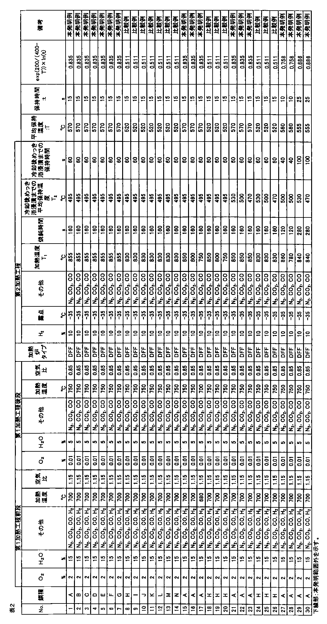
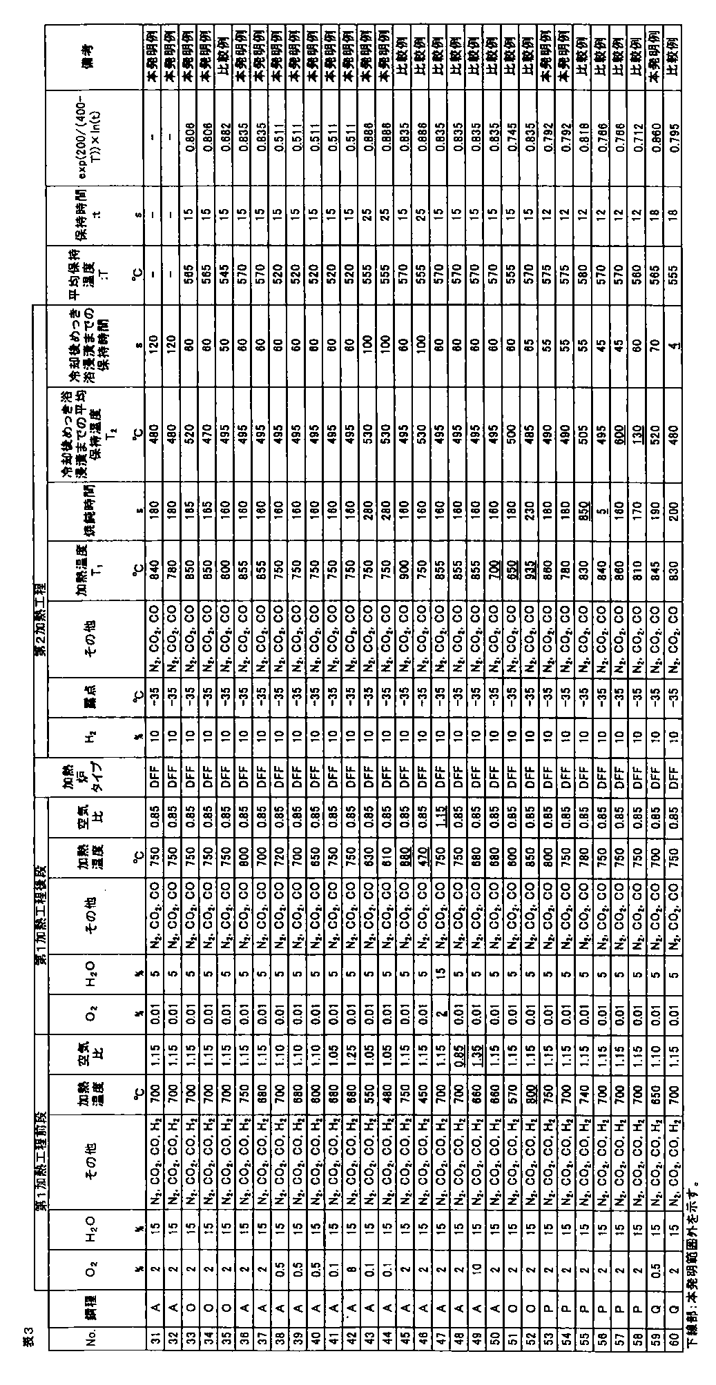
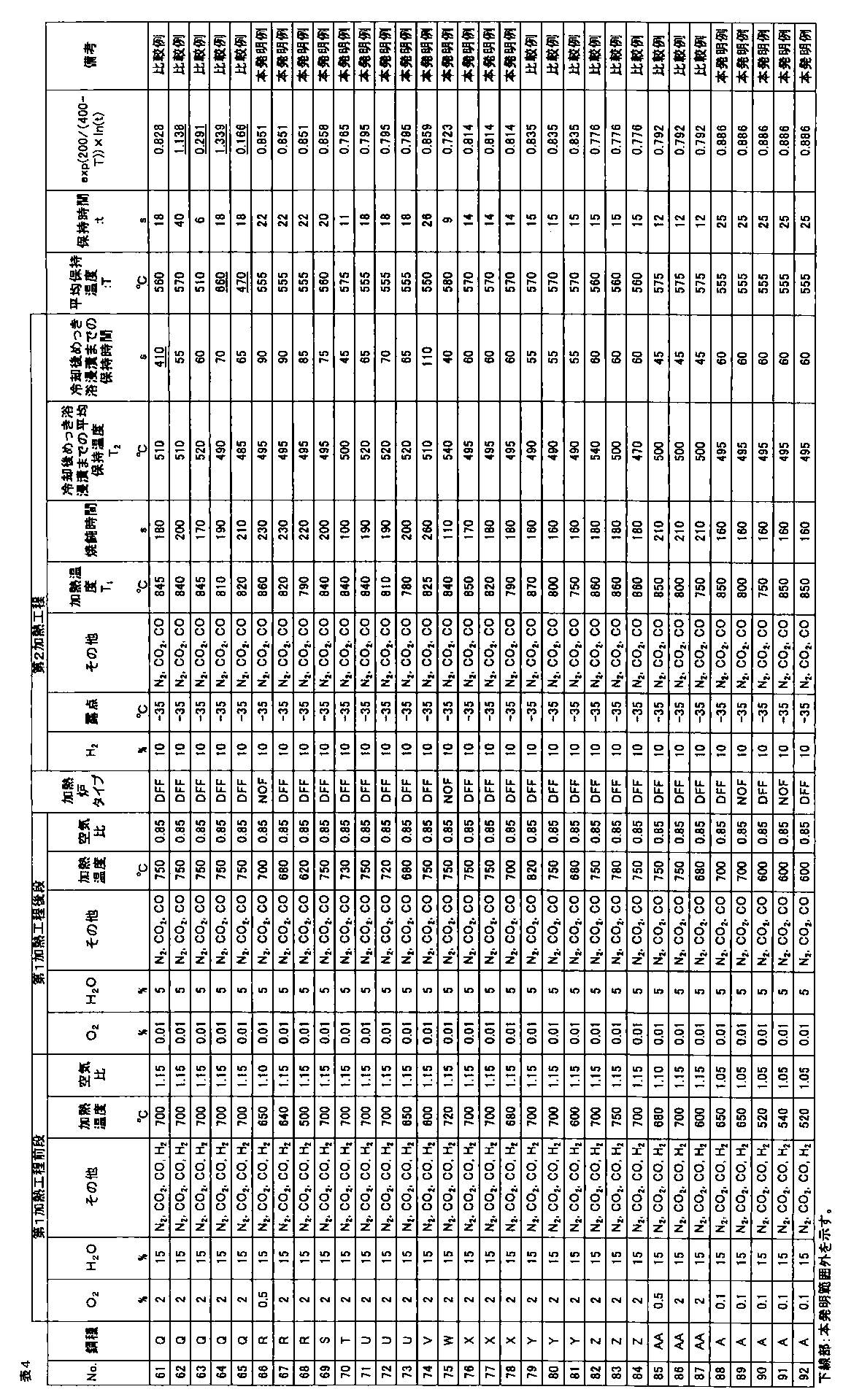
- the first stage of the first heating step is performed by a direct flame furnace or a non-oxidizing furnace under an air ratio of 1 to 1.3, and the latter stage of the first heating step is performed by a direct flame furnace or a non-oxidizing furnace.
- an alloying treatment of galvanizing is performed under a condition satisfying the following formula in a temperature range of 500 to 600 ° C .: (1) to (5) Of high-strength hot-dip galvanized steel sheet with excellent material stability, workability, and plating appearance. 0.45 ⁇ exp [200 / (400 ⁇ T)] ⁇ ln (t) ⁇ 1.0 However, T: Average holding temperature in the temperature range of 500 to 600 ° C (° C) t: Holding time in the temperature range of 500 to 600 ° C. (s) exp (X) and ln (X) denote the exponential function and natural logarithm of X, respectively.
- the “high-strength galvanized steel sheet” is a galvanized steel sheet having a tensile strength TS of 540 MPa or more.
- the hot dip galvanized steel sheet in the present invention includes both a hot dip galvanized steel sheet that has not been subjected to an alloying treatment and an alloyed hot dip galvanized steel sheet that has been subjected to an alloying treatment.
- a high-strength hot-dip galvanized steel sheet having a tensile strength TS of 540 MPa or more, excellent workability and material stability due to high ductility and high hole expansibility, and excellent plating appearance. Is obtained.
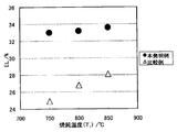
- FIG. 1 is a diagram showing the relationship between annealing temperature (T 1 ) and TS.
- FIG. 2 is a diagram showing the relationship between the annealing temperature (T 1 ) and EL.
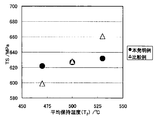
- FIG. 3 is a diagram showing the relationship between the cooling average holding temperature (T 2 ) and TS.
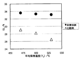
- FIG. 4 is a graph showing the relationship between the cooling average holding temperature (T 2 ) and EL.
- (A) C 0.04% or more and 0.13% or less C is an austenite-forming element and an element essential for strengthening steel. If the C content is less than 0.04%, it is difficult to ensure the desired strength. On the other hand, if the C content exceeds 0.13%, the welded part and the heat-affected part are markedly cured, and the mechanical properties of the welded part deteriorate, so that spot weldability, arc weldability, and the like are lowered. Therefore, the C content is set to 0.04% or more and 0.13% or less.
- Si 0.7% or more and 2.3% or less
- Si is a ferrite-forming element and also an element effective for solid solution strengthening.
- the Si content is 0.7% or more and 2.3% or less.
- it is 1.2% or more and 1.8% or less.
- Mn is an element effective for strengthening steel.
- it is an element that stabilizes austenite, and is an element necessary for adjusting the fraction of the second phase. For this reason, it is necessary to contain Mn 0.8% or more.
- the content exceeds 2.0%, the martensite area ratio in the second phase increases, and it becomes difficult to ensure material stability.
- the alloy cost of Mn has risen in recent years, it also leads to a cost increase factor. Therefore, the Mn content is 0.8% or more and 2.0% or less. Preferably they are 1.0% or more and 1.8% or less.
- P 0.1% or less P is an element effective for strengthening steel. However, if P is contained excessively in excess of 0.1%, embrittlement occurs due to segregation at the grain boundaries, and impact resistance is reduced. Deteriorate. On the other hand, if the content exceeds 0.1%, the alloying rate is significantly delayed. Therefore, the P content is 0.1% or less.
- S 0.01% or less S is an inclusion such as MnS, which causes deterioration of impact resistance and cracks along the metal flow of the welded portion, so the content is as low as possible. However, from the viewpoint of manufacturing cost, the S content is set to 0.01% or less.
- (F) Al 0.1% or less
- the content of Al exceeds 0.1%, coarse Al 2 O 3 is generated and the material deteriorates. For this reason, Al content shall be 0.1% or less.
- the content is preferably 0.01% or more. Therefore, a preferable range of the Al content is 0.01 to 0.1%.
- N is an element that causes the most deterioration in the aging resistance of steel, and the smaller the value, the more preferable. When the content exceeds 0.008%, the deterioration of aging resistance is remarkable. Become. Therefore, the N content is 0.008% or less.
- the balance is Fe and inevitable impurities.
- at least one selected from the following elements can be added as necessary.
- Ni and Cu are effective elements for strengthening steel and can be added as necessary. It also has the effect of promoting internal oxidation and improving plating adhesion. However, if Ni and Cu are contained in excess of 1.0%, the workability of the steel sheet is lowered. In addition, the cost increases. Therefore, when adding Ni and Cu, the content is made 1.0% or less, respectively. Moreover, in order to exhibit the said effect effectively, it is preferable that content of Ni and Cu is 0.05% or more, respectively.
- Ti and Nb are effective elements for precipitation strengthening of steel and are necessary It can be added depending on. However, if the respective contents exceed 0.1%, the workability and the shape freezing property decrease. In addition, the cost increases. Therefore, when adding Ti and Nb, the content is 0.1% or less, respectively. Moreover, in order to exhibit the said effect effectively, it is preferable that content of Ti and Nb is 0.01% or more, respectively.
- B has the effect of suppressing the formation and growth of ferrite from the austenite grain boundaries, and can be added as necessary. However, if it exceeds 0.0050%, the workability decreases. In addition, the cost increases. Therefore, when adding B, the content is made 0.0050% or less. Moreover, in order to exhibit the said effect effectively, it is preferable that the content is 0.0003% or more.
- Ca and REM are sulfides that spheroidize the shape of the sulfide and make it expandable It is an effective element to improve the adverse effects of However, if it is contained excessively, inclusions and the like are increased and surface and internal defects are caused. Therefore, when adding Ca and REM, the content shall be 0.005% or less, respectively. Moreover, in order to exhibit the said effect effectively, it is preferable that the content is 0.001% or more, respectively.
- ferrite In addition to ferrite, bainitic ferrite, pearlite, and martensite, carbides such as retained austenite, tempered martensite, and cementite may be generated. However, the above ferrite, bainitic ferrite, pearlite, and martensite may be generated. If the area ratio is satisfied, the object of the present invention can be achieved.
- the area ratio of ferrite, bainitic ferrite, pearlite, and martensite in the present invention is the area ratio of each phase in the observation area.
- the high-strength hot-dip galvanized steel sheet of the present invention uses a steel sheet having the above component composition and the above steel structure as a base steel sheet, and a plated film obtained by hot-dip galvanizing, or a plated film that has been subjected to alloying treatment after hot-dip galvanizing. Have.
- the high-strength hot-dip galvanized steel sheet of the present invention is subjected to the two-step heat treatment described below on a steel sheet obtained from a steel having a component composition suitable for the above-described component composition range, and then hot-dip galvanized. Or by performing an alloying treatment after hot dip galvanization.
- hot rolling it is preferable to heat the slab to 1100 to 1300 ° C., perform hot rolling at a final finishing temperature of 850 ° C. or higher, and wind it on a steel strip at 400 to 650 ° C.
- the coiling temperature exceeds 650 ° C., the carbides in the hot-rolled sheet are coarsened, and such coarsened carbides cannot be melted during soaking at the time of annealing, so that the required strength may not be obtained. .
- the hot-rolled steel sheet thus obtained may be used as the steel sheet, or the hot-rolled steel sheet after pickling is further used as the steel sheet after cold rolling. May be.
- cold rolling it is not necessary to specifically limit the conditions, but it is preferable to perform cold rolling at a cold reduction rate of 30% or more. If the cold rolling reduction is low, recrystallization of ferrite is not promoted, unrecrystallized ferrite remains, and ductility and hole expansibility may decrease.
- O 2 is set to 0.1 vol% or more due to the need for sufficient amount of an oxidation.
- O 2 is preferably 20 vol% or less of the atmospheric level.
- H 2 O is made 1 vol% or more in order to promote oxidation. In consideration of the humidification cost, H 2 O is preferably 50 vol% or less. If the temperature after heating in the former step is less than 400 ° C., it is difficult to oxidize, and if it exceeds 750 ° C., the iron oxide is peeled off by the roll in the second heating step. Heat to below °C.
- the latter stage of the first heating process is performed to reduce the surface of the steel plate once oxidized and suppress the pressing. Therefore, it is possible to reduce the surface of the steel sheet by heating in the latter stage, and the steel sheet that is once oxidized in the former stage is heated under conditions where iron oxide peeling does not occur, that is, under conditions of low-temperature reducing heating in a low oxygen concentration atmosphere.
- the surface is subjected to reduction treatment to such an extent that iron oxide does not peel off in the next second heating step.
- O 2 since O 2 cannot be reduced when O 2 is 0.1 vol% or more, O 2 is set to less than 0.1 vol%. However, it is necessary to set it as 0.01 vol% or more.
- H 2 O is contained in a large amount, the steel sheet is oxidized, so the content is set to 20 vol% or less. However, 1 vol% or more of H 2 O is necessary.
- the steel plate temperature is less than 600 ° C., it is difficult to reduce, and when it exceeds 850 ° C., heating costs are required. Therefore, in the latter stage, the steel plate temperature is heated to a temperature in the range of 600 ° C. to 850 ° C.
- pre-stage heating is performed by a direct-fired furnace (DFF) or non-oxidizing furnace (NOF)
- DFF direct-fired furnace
- NOF non-oxidizing furnace
- the combustion gas is C gas generated in a coke oven and the air ratio is 0.6 to less than 1. . This is because if the air ratio is 1 or more, iron oxide on the surface of the steel sheet cannot be reduced, and if the air ratio is less than 0.6, the combustion efficiency deteriorates.
- the second heating step is performed subsequent to the first heating step, and is for adjusting the reduction treatment and the steel sheet structure, and includes H 2 : 1 to 50 vol% and has a dew point of 0.
- the steel sheet is held for 15 to 600 s in a temperature range of 750 to 900 ° C. in an atmosphere of less than or equal to 0 ° C., cooled to a temperature range of 450 to 550 ° C., and then held for 10 to 200 s in the temperature range of 450 to 550 ° C.
- ⁇ H 2 An atmosphere containing 1 to 50 vol% and a dew point of 0 ° C. or less
- the iron oxide generated in the first heating step is difficult to be reduced, so the first heating step Even if sufficient iron oxide is generated to ensure the plating property, the plating property deteriorates.
- Annealing to hold for 15 to 600 s in a temperature range of 750 to 900 ° C specifically, an austenite single phase region or a two-phase region of austenite and ferrite.
- the annealing temperature is less than 750 ° C. or the holding time is less than 15 s, the hard cementite in the steel sheet is not sufficiently dissolved, so that the hole expandability is lowered, and the desired martensite area ratio cannot be obtained, and the ductility is lowered. To do.
- the annealing temperature exceeds 900 ° C.
- the growth of austenite grains is remarkable, and it becomes difficult to secure bainitic ferrite due to the bainite transformation that occurs during holding after cooling, so that the hole expandability decreases, and martensite
- the area ratio / (bainitic ferrite area ratio + pearlite area ratio) exceeds 0.6, good material stability cannot be obtained.
- the holding time exceeds 600 s, austenite becomes coarse, and it is difficult to secure a desired strength, and it may cause an increase in cost due to a large energy consumption.
- a high-strength hot-dip galvanized steel sheet having a tensile strength TS of 540 MPa or more, excellent workability and material stability, and excellent plating appearance can be obtained.
- the holding temperature does not need to be constant as long as it is within the above-mentioned temperature range, and even if the cooling rate changes during cooling, it may be within the specified range. That's fine.
- the steel plate may be heat-processed with what kind of equipment.
- temper rolling of the steel sheet of the present invention for shape correction after heat treatment is also included in the scope of the present invention.
- the steel sheet of the present invention is typically produced through various processes such as normal steelmaking, casting, hot rolling, etc., but omits part or all of the hot rolling process by thin casting, for example. May be manufactured.
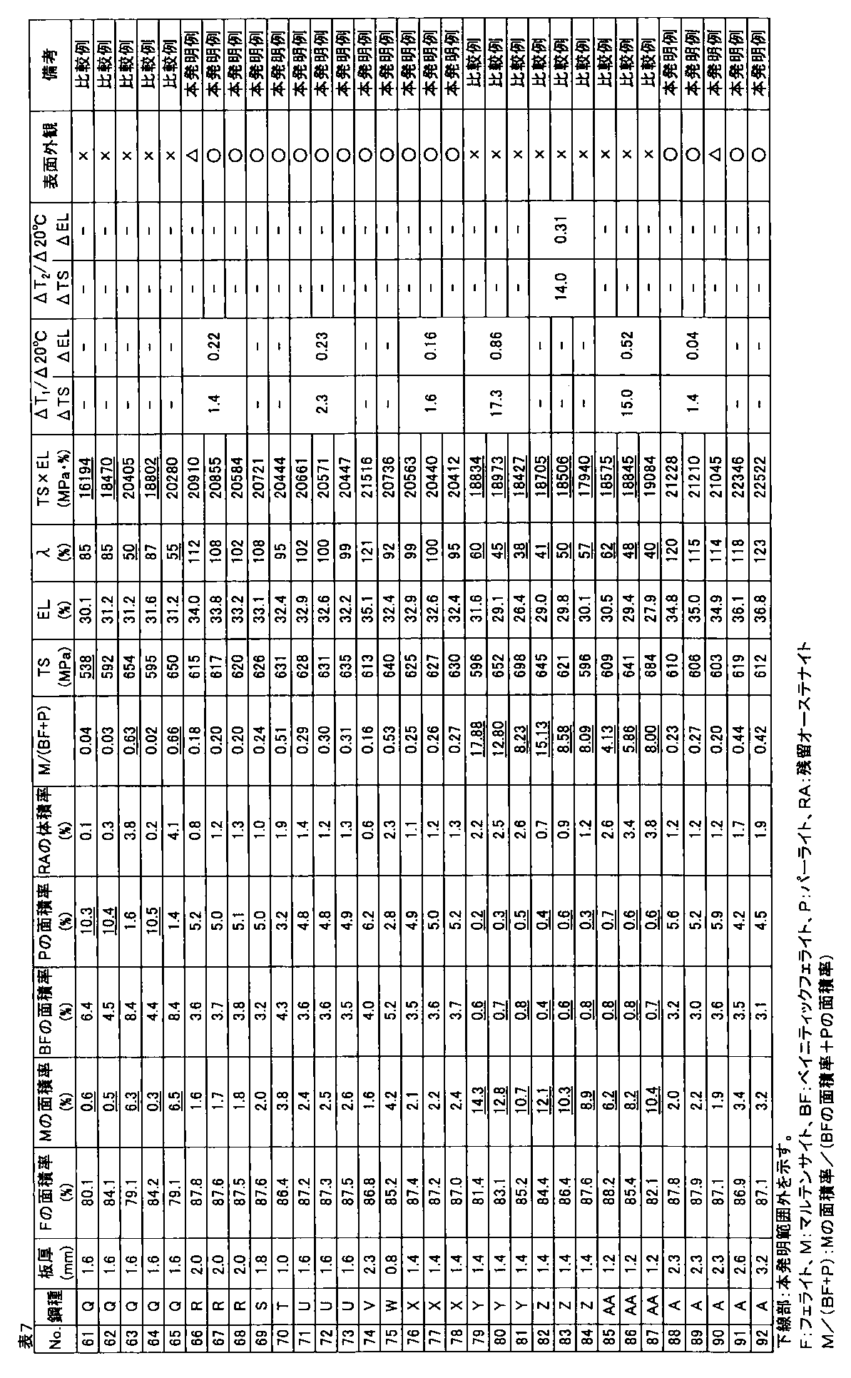
- the galvanized steel sheet was obtained by alloying the plating layer (cold-rolled steel sheet base hot-dip galvanized material: No. 1 to 90, hot-rolled steel sheet base hot-dip galvanized material: Nos. 91 and 92). The amount of plating was 30 to 50 g / m 2 per side. A part of a hot-dip galvanized steel sheet that was not subjected to alloying treatment after hot-dip galvanizing treatment was also produced.
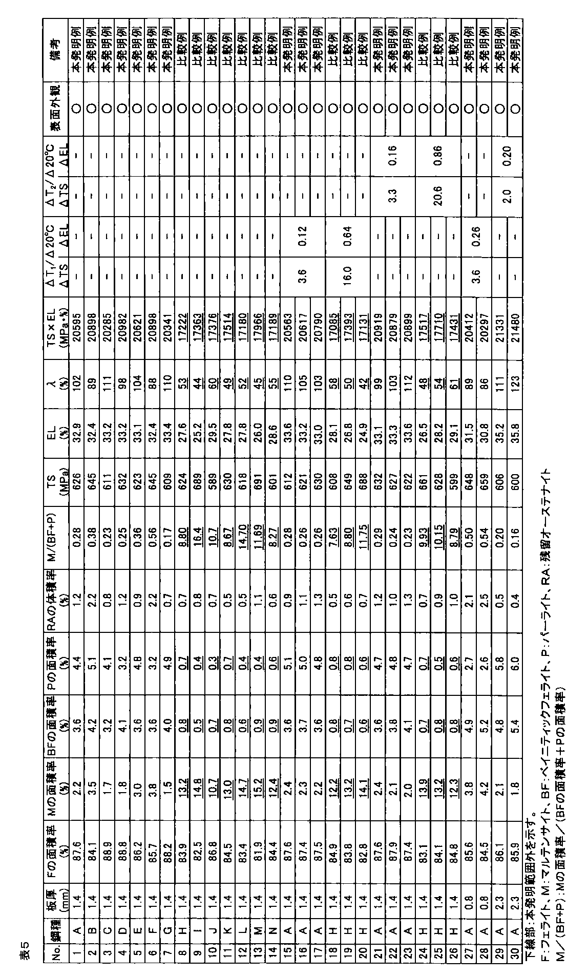
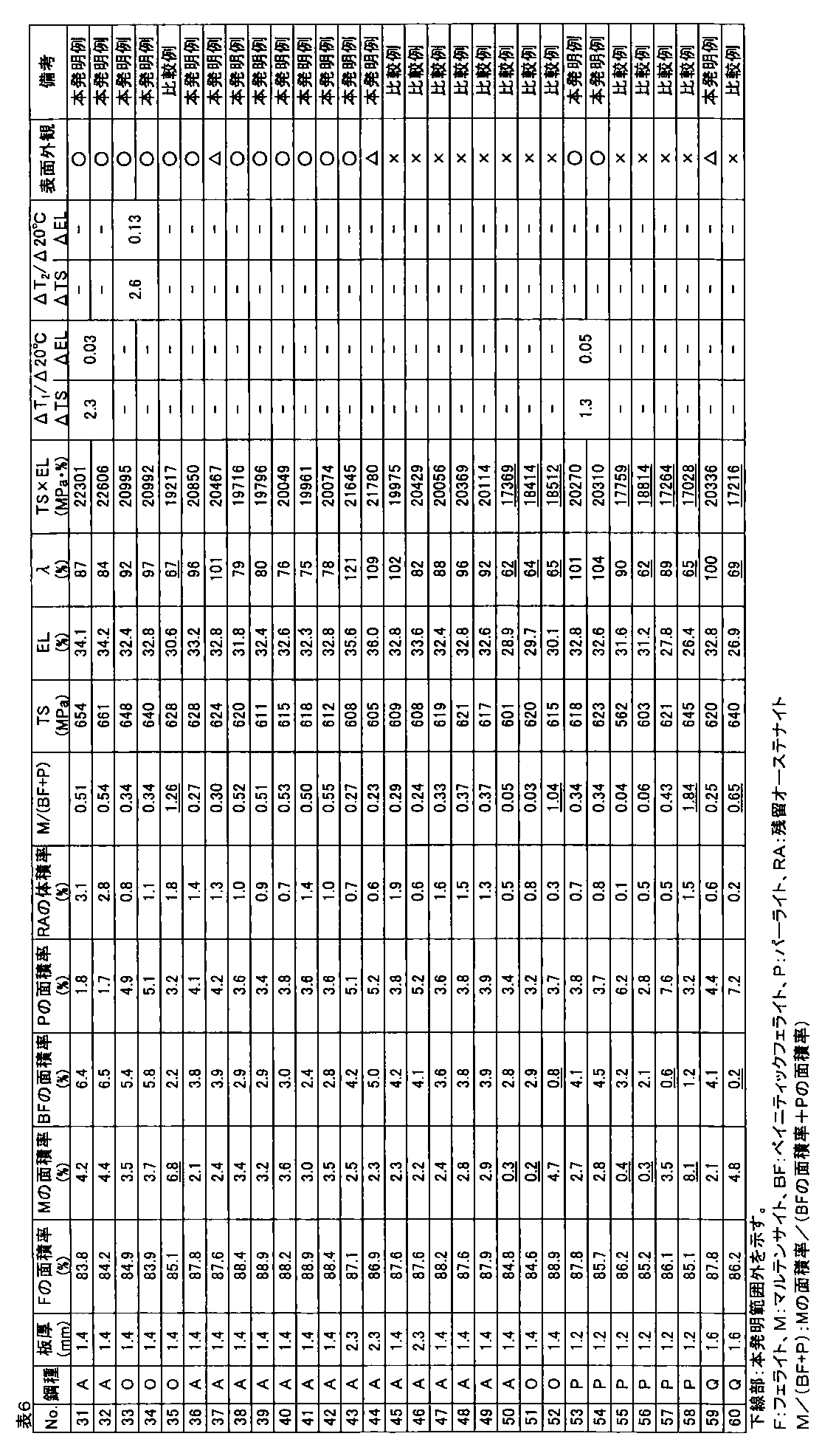
- the area ratio of ferrite, bainitic ferrite, pearlite, and martensite phase with respect to the obtained hot dip galvanized steel sheet was corroded with 3% nital after polishing the plate thickness section parallel to the rolling direction of the steel sheet, and SEM Ten fields of view were observed using a (scanning electron microscope) at a magnification of 2000 times, and obtained using Image-Pro of Media Cybernetics.
- the obtained hot-dip galvanized steel sheet was subjected to tempering treatment at 200 ° C. for 2 hours, and then the structure of the plate thickness section parallel to the rolling direction of the steel sheet was described above.
- the area ratio of the tempered martensite phase obtained by the above method was defined as the area ratio of the martensite phase.
- the volume ratio of the retained austenite phase was obtained by polishing the steel plate to a 1 ⁇ 4 surface in the plate thickness direction and diffracting X-ray intensity of the 1 ⁇ 4 surface thickness. CoK ⁇ rays are used as incident X-rays, and the peaks of ⁇ 111 ⁇ , ⁇ 200 ⁇ , ⁇ 220 ⁇ , ⁇ 311 ⁇ planes of retained austenite phase and ⁇ 110 ⁇ , ⁇ 200 ⁇ , ⁇ 211 ⁇ planes of ferrite phase are used. Intensity ratios were obtained for all combinations of integrated intensities, and the average value of these ratios was taken as the volume ratio of the retained austenite phase.
- the tensile test is performed in accordance with JIS Z 2241 using a JIS No. 5 test piece obtained by taking a sample so that the tensile direction is perpendicular to the rolling direction of the steel sheet, and TS (tensile strength), EL (all Elongation) was measured, and when TS ⁇ EL ⁇ 19000 MPa ⁇ %, the ductility was determined to be good.
- the hole expansibility was measured with respect to the hot dip galvanized steel sheet obtained by the above.
- the hole expandability was performed in accordance with Japan Iron and Steel Federation Standard JFST1001. After each steel plate obtained was cut to 100 mm ⁇ 100 mm, a hole having a diameter of 10 mm or more was punched with a clearance of 12% ⁇ 1% when the thickness was 2.0 mm or more, and a clearance of 12% ⁇ 2% when the thickness was less than 2.0 mm.
- Limit hole expansion ratio ⁇ (%) ⁇ (D f ⁇ D 0 ) / D 0 ⁇ ⁇ 100
- D f hole diameter at crack initiation (mm) D 0 is the initial hole diameter (mm).
- the surface appearance was investigated by the following method. Judging by visual inspection for appearance defects such as non-plating and pushing rods, good ( ⁇ ) when there is no appearance defect, good ( ⁇ ) when there is a slight but poor appearance. When there was an appearance defect, it was determined as a defect (x).
- TS is 540 MPa or more
- ⁇ is 70% or more
- the hole expandability is excellent
- TS ⁇ EL ⁇ 19000 MPa ⁇ %.
- ⁇ TS and ⁇ EL are small, and a high-strength hot-dip galvanized steel sheet excellent in material stability is obtained.
- one or more of ductility and hole expansibility are inferior, or material stability is not preferable.
- the high-strength hot-dip galvanized steel sheet of the present invention example is not plated and excellent in surface appearance, but in the comparative example, it is understood that non-plating occurs and the surface appearance is inferior.
- the high-strength hot-dip galvanized steel sheet of the present invention has a tensile strength TS of 540 MPa or more, has high ductility and high hole expansibility, and is excellent in material stability.
Abstract
Description
・ベイニティックフェライトやパーライトの活用により、軟質なフェライトと硬質なマルテンサイトの硬度差を緩和でき、穴拡げ性の向上が可能となる。
・最終組織に硬質なマルテンサイトが多く存在すると軟質なフェライト相の異相界面で大きな硬度差が生じ、穴拡げ性が低下するため、最終的にマルテンサイトに変態する未変態オーステナイトをパーライト化し、フェライト、ベイニティックフェライト、パーライト、少量のマルテンサイトを有する組織を造り込むことで、高延性を維持したままで、穴拡げ性の向上が可能となり、さらに、上記各相の面積率を適正に制御することにより、材質安定性の確保が可能となる。
0.45≦exp[200/(400−T)]×ln(t)≦1.0
ただし、
T:500~600℃の温度域での平均保持温度(℃)
t:500~600℃の温度域の保持時間(s)
exp(X)、ln(X)は、それぞれXの指数関数、自然対数を示す。
(1)まず、成分組成について説明する。
Cはオーステナイト生成元素であり、鋼の強化に不可欠な元素である。C含有量が0.04%未満では、所望の強度確保が難しい。一方、C含有量が0.13%を超えると、溶接部および熱影響部の硬化が著しく、溶接部の機械的特性が劣化するため、スポット溶接性、アーク溶接性等が低下する。よって、C含有量は0.04%以上0.13%以下とする。
Siはフェライト生成元素であり、また、固溶強化に有効な元素でもある。フェライト相の加工硬化能向上による良好な延性確保のためにはSiを0.7%以上含有させることが必要である。さらに、所望のベイニティックフェライト相の面積率を確保し、良好な穴拡げ性を確保するためにも0.7%以上含有させることが必要である。しかしながら、Siを過剰に含有させると、赤スケール等の発生により表面性状の劣化や、めっき付着・密着性の劣化を引き起こす。よって、Si含有量は0.7%以上2.3%以下とする。好ましくは、1.2%以上1.8%以下である。
Mnは、鋼の強化に有効な元素である。また、オーステナイトを安定化させる元素であり、第二相の分率調整に必要な元素である。このため、Mnは0.8%以上含有させる必要がある。一方、2.0%を超えて過剰に含有させると、第二相中のマルテンサイト面積率が増加し、材質安定性の確保が困難となる。また、近年Mnの合金コストが高騰しているため、コストアップの要因にも繋がる。したがって、Mn含有量は0.8%以上2.0%以下とする。好ましくは1.0%以上1.8%以下である。
Pは、鋼の強化に有効な元素であるが、0.1%を超えて過剰に含有させると、粒界偏析により脆化を引き起こし、耐衝撃性を劣化させる。また、含有量が0.1%を超えると合金化速度を大幅に遅延させる。したがって、P含有量は0.1%以下とする。
Sは、MnSなどの介在物となって、耐衝撃性の劣化や溶接部のメタルフローに沿った割れの原因となるので、その含有量は極力低い方がよいが、製造コストの面からS含有量を0.01%以下とする。
Alは、その含有量が0.1%を超えると、粗大なAl2O3が生成し、材質が劣化する。このため、Al含有量を0.1%以下とする。また、Alは鋼の脱酸のために添加される場合、その含有量が0.01%未満ではMnやSiなどの粗大な酸化物が鋼中に多数分散して材質が劣化することになるため、含有量を0.01%以上とするのが好ましい。したがって、Al含有量の好ましい範囲は、0.01~0.1%である。
Nは、鋼の耐時効性を最も大きく劣化させる元素であり、少ないほど好ましく、その含有量が0.008%を超えると耐時効性の劣化が顕著となる。したがって、N含有量は0.008%以下とする。
Cr、V、Moは強度と延性のバランスを向上させる作用を有するので必要に応じて添加することができる。しかしながら、それぞれCr:1.0%、V:0.5%、Mo:0.5%を超えて過剰に添加すると、第二相の分率が過大となり著しい強度上昇等の懸念が生じる。また、コストアップの要因にもなる。従って、これらの元素を添加する場合には、その量をそれぞれCr:1.0%以下、V:0.5%以下、Mo:0.5%以下とする。上記効果を有効に発揮させるためには、Cr:0.05%以上、V:0.005%以上、Mo:0.005%以上であることが好ましい。
Ti、Nbは鋼の析出強化に有効な元素であり、必要に応じて添加することができる。しかし、それぞれの含有量が0.1%を超えると加工性および形状凍結性が低下する。また、コストアップの要因にもなる。したがって、Ti、Nbを添加する場合には、その含有量を、それぞれ0.1%以下とする。また、上記効果を有効に発揮するためには、Ti、Nbの含有量はそれぞれ0.01%以上であることが好ましい。
CaおよびREM(Rare Earth Metal)は、硫化物の形状を球状化し穴拡げ性への硫化物の悪影響を改善するために有効な元素である。しかしながら、過剰に含有させると、介在物等の増加を引き起こし表面および内部欠陥などを引き起こす。したがって、Ca、REMを添加する場合は、その含有量はそれぞれ0.005%以下とする。また、上記効果を有効に発揮するためには、その含有量はそれぞれ0.001%以上であることが好ましい。
(a)フェライト相の面積率:75%以上
良好な延性を確保するためには、フェライト相は面積率で75%以上必要である。
良好な穴拡げ性の確保のためには、軟質なフェライトと硬質なマルテンサイトの硬度差を緩和させることが必要であり、そのために、ベイニティックフェライト相が面積率で1.0%以上必要である。
良好な穴拡げ性の確保のため、パーライト相の面積率は1.0%以上とする。所望の強度−延性バランスを確保するため、パーライト相の面積率を10.0%以下とする。
所望の強度−延性バランスを確保するため、マルテンサイト相の面積率は1.0%以上とする。良好な材質安定性を確保するために、引張特性(TS、EL)に大きく影響を及ぼすマルテンサイト相の面積率は5.0%未満である必要がある。
良好な材質安定性を確保するために、第二相の相構成を、材質バラツキの要因となるマルテンサイトの量を低減し、マルテンサイトより軟質なベイニティックフェライトやパーライトの量を多くすること、つまり、マルテンサイト面積率/(ベイニティックフェライト面積率+パーライト面積率)≦0.6を満たす必要がある。
本発明の高強度溶融亜鉛めっき鋼板は、上記の成分組成範囲に適合した成分組成を有する鋼から得られた鋼板に対し、以下に説明する2工程の加熱処理を行い、その後溶融亜鉛めっきを施すこと、または溶融亜鉛めっきを施した後に合金化処理を施すことにより製造する。
上記の成分組成を有する鋼を、公知の方法により、溶製した後、分塊または連続鋳造を経てスラブとし、熱間圧延して熱延板にする。熱間圧延を行うに際しては、スラブを1100~1300℃に加熱し、最終仕上げ温度を850℃以上で熱間圧延を施し、400~650℃で鋼帯に巻き取ることが好ましい。巻き取り温度が650℃を超えた場合、熱延板中の炭化物が粗大化し、このような粗大化した炭化物は焼鈍時の均熱中に溶けきらないため、必要強度を得ることができない場合がある。その後、公知の方法で酸洗処理を行う。このようにして得られた熱延鋼板を上記鋼板として用いてもよいし、酸洗を行った後の熱延鋼板に対し、さらに冷間圧延を行った後の冷延鋼板を上記鋼板として用いてもよい。冷間圧延を行うに際しては、特にその条件を限定する必要はないが、30%以上の冷間圧下率で冷間圧延を施すことが好ましい。冷間圧下率が低いと、フェライトの再結晶が促進されず、未再結晶フェライトが残存し、延性と穴拡げ性が低下する場合があるためである。
(i)第1加熱工程
第1加熱工程は、前段において、O2:0.1~20vol%、H2O:1~50vol%を含有する雰囲気中で鋼板を400~750℃の範囲内の温度になるように加熱し、後段において、O2:0.01~0.1vol%未満、H2O:1~20vol%を含有する雰囲気中で鋼板を600~850℃の範囲内の温度になるように加熱する。
第1加熱工程前段は鋼板を酸化させるために行うものであり、O2は酸化を行うのに十分な量が必要であるため0.1vol%以上とする。また、経済的な理由から、O2は大気レベルの20vol%以下が好ましい。H2Oは酸化を促進するために1vol%以上とする。また、加湿コストを考慮すると、H2Oは50vol%以下が好ましい。前段工程で加熱後の温度が400℃未満では酸化しにくく、750℃を超えると酸化しすぎて第2加熱工程内のロールで酸化鉄が剥離するので、前段では、鋼板温度が400℃以上750℃以下となるように加熱する。
第1加熱工程後段は一旦酸化された鋼板表面を還元処理し、押し疵を抑制するために行う。そのため後段の加熱では鋼板表面を還元処理することが可能で、かつ、酸化鉄の剥離が起こらない条件、すなわち低酸素濃度雰囲気で低温還元加熱の条件で加熱を行い、前段で一旦酸化された鋼板表面を、次の第2加熱工程内で酸化鉄の剥離が起こらない程度まで還元処理する。この際にO2が0.1vol%以上では還元できないのでO2は0.1vol%未満とする。ただし、0.01vol%以上とすることが必要である。H2Oは多量に含まれると鋼板が酸化されるので20vol%以下とする。ただし、1vol%以上のH2Oは必要である。鋼板温度が、600℃未満では還元しにくく、850℃を超えると加熱コストがかかるため、後段では鋼板温度が600℃以上850℃以下の範囲内の温度となるように加熱する。
第2加熱工程は、第1加熱工程に引き続いて行われ、還元処理および鋼板組織の調整を行うためのものであり、H2:1~50vol%を含み露点が0℃以下の雰囲気中で鋼板を750~900℃の温度域で15~600s保持し、450~550℃の温度域に冷却した後、該450~550℃の温度域で10~200s保持する。
H2が1vol%未満、露点が0℃超になると第1加熱工程で生成した酸化鉄が還元されにくいため、第1加熱工程においてめっき性を確保するのに十分な酸化鉄が生成しても、かえってめっき性が劣化するようになる。また、H2が50vol%を超えるとコストアップにつながる。露点が−60℃未満では工業的に実施が困難であるため、露点は−60℃以上が好ましい。
750~900℃の温度域、具体的には、オーステナイト単相域、もしくはオーステナイトとフェライトの二相域で、15~600s保持する焼鈍を行う。焼鈍温度が750℃未満または保持時間が15s未満になると、鋼板中の硬質なセメンタイトが十分に溶解しないため穴拡げ性が低下し、また、所望のマルテンサイト面積率が得られないため延性が低下する。一方、焼鈍温度が900℃を超えると、オーステナイト粒の成長が著しく、冷却後の保持中に生じるベイナイト変態によるベイニティックフェライトの確保が困難となるため穴拡げ性が低下し、また、マルテンサイト面積率/(ベイニティックフェライト面積率+パーライト面積率)が0.6を超えるため良好な材質安定性が得られない。さらに、保持時間が600sを超えると、オーステナイトが粗大化し、所望の強度確保が困難となり、また、多大なエネルギー消費にともなうコスト増を引き起こす場合がある。
前記の焼鈍を行った後、450~550℃の温度域に冷却し、該450~550℃の温度域に10~200s保持する。保持温度が550℃を超える、または保持時間が10s未満になると、ベイナイト変態が促進せず、ベイニティックフェライトの面積率が1.0%未満になるため、所望の穴拡げ性を得られない。また、保持温度が450℃未満、または保持時間が200sを超えると、第二相の大半がベイナイト変態の促進により生成した固溶炭素量の多いオーステナイトとベイニティックフェライトになり、所望の1.0%以上のパーライト面積率が得られず、かつ、硬質なマルテンサイト相の面積率が5.0%以上となるため、良好な穴拡げ性と材質安定性が得られない。
上記第2加熱工程の後、鋼板を通常の浴温のめっき浴中に浸入させて溶融亜鉛めっきを施し、ガスワイピングなどでめっき付着量を調整し、冷却することで、めっき層を合金化していない溶融亜鉛めっき鋼板を得る。
0.45≦exp[200/(400−T)]×ln(t)≦1.0
ただし、
T:500~600℃の温度域での平均保持温度(℃)
t:500~600℃の温度域の保持時間(s)
exp(X)、ln(X)は、それぞれXの指数関数、自然対数を示す。

限界穴広げ率λ(%)={(Df−D0)/D0}×100
ただし、Dfは亀裂発生時の穴径(mm)、D0は初期穴径(mm)である。
不めっきや押し疵などの外観不良の有無を目視にて判断し、外観不良がない場合には良好(○)、外観不良がわずかにあるがおおむね良好である場合にはおおむね良好(△)、外観不良がある場合には不良(×)と判定した。
Claims (6)
- 質量%でC:0.04%以上0.13%以下、Si:0.7%以上2.3%以下、Mn:0.8%以上2.0%以下、P:0.1%以下、S:0.01%以下、Al:0.1%以下、N:0.008%以下を含有し、残部がFeおよび不可避的不純物からなる鋼板に対し、
前段においてO2:0.1~20vol%、H2O:1~50vol%を含有する雰囲気中で400~750℃の範囲内の温度になるように加熱し、後段においてO2:0.01~0.1vol%未満、H2O:1~20vol%を含有する雰囲気中で600~850℃の範囲内の温度になるように加熱する第1加熱工程を施し、
次いで、H2:1~50vol%を含み露点が0℃以下の雰囲気中で750~900℃の温度域で15~600s保持し、450~550℃の温度域に冷却した後、該450~550℃の温度域で10~200s保持する第2加熱工程を施した後、
溶融亜鉛めっき処理を施し、
面積率で、75%以上のフェライト相と、1.0%以上のベイニティックフェライト相と、1.0%以上10.0%以下のパーライト相を有し、さらに、マルテンサイト相の面積率が1.0%以上5.0%未満で、かつ、マルテンサイト面積率/(ベイニティックフェライト面積率+パーライト面積率)≦0.6を満たす溶融亜鉛めっき鋼板を得ることを特徴とする、材質安定性、加工性およびめっき外観に優れた高強度溶融亜鉛めっき鋼板の製造方法。 - 前記鋼板は、さらに、質量%で、Cr:1.0%以下、V:0.5%以下、Mo:0.5%以下、Ni:1.0%以下、Cu:1.0%以下のうちから選ばれる少なくとも1種の元素を含有することを特徴とする請求項1に記載の材質安定性、加工性およびめっき外観に優れた高強度溶融亜鉛めっき鋼板の製造方法。
- 前記鋼板は、さらに、質量%で、Ti:0.1%以下、Nb:0.1%以下、B:0.0050%以下のうちから選ばれる少なくとも1種の元素を含有することを特徴とする請求項1または請求項2に記載の材質安定性、加工性およびめっき外観に優れた高強度溶融亜鉛めっき鋼板の製造方法。
- 前記鋼板は、さらに、質量%で、Ca:0.005%以下、REM:0.005%以下のうちから選ばれる少なくとも1種の元素を含有することを特徴とする請求項1から請求項3のいずれか1項に記載の材質安定性、加工性およびめっき外観に優れた高強度溶融亜鉛めっき鋼板の製造方法。
- 前記第1加熱工程前段は直火炉または無酸化炉により、空気比が1以上1.3以下の条件で行い、前記第1加熱工程後段は直火炉または無酸化炉により、空気比が0.6以上1未満の条件で行うことを特徴とする請求項1から請求項4のいずれか1項に記載の材質安定性、加工性およびめっき外観に優れた高強度溶融亜鉛めっき鋼板の製造方法。
- 前記溶融亜鉛めっき処理後に、500~600℃の温度域において下式を満たす条件で亜鉛めっきの合金化処理を施すことを特徴とする請求項1から請求項5のいずれか1項に記載の材質安定性、加工性およびめっき外観に優れた高強度溶融亜鉛めっき鋼板の製造方法。
0.45≦exp[200/(400−T)]×ln(t)≦1.0
ただし、
T:500~600℃の温度域での平均保持温度(℃)
t:500~600℃の温度域の保持時間(s)
exp(X)、ln(X)は、それぞれXの指数関数、自然対数を示す。
Priority Applications (6)
| Application Number | Priority Date | Filing Date | Title |
|---|---|---|---|
| KR1020137032500A KR101585311B1 (ko) | 2011-06-01 | 2012-06-01 | 재질 안정성, 가공성 및 도금 외관이 우수한 고강도 용융 아연 도금 강판의 제조 방법 |
| CA2835809A CA2835809C (en) | 2011-06-01 | 2012-06-01 | Method for manufacturing high strength galvanized steel sheet having excellent stability of mechanical properties, formability, and coating appearance |
| CN201280027107.4A CN103597102B (zh) | 2011-06-01 | 2012-06-01 | 材质稳定性、加工性和镀层外观优良的高强度热镀锌钢板的制造方法 |
| US14/119,656 US9340859B2 (en) | 2011-06-01 | 2012-06-01 | Method for manufacturing high strength galvanized steel sheet having excellent stability of mechanical properties, formability, and coating appearance |
| MX2013014134A MX336836B (es) | 2011-06-01 | 2012-06-01 | Metodo para la fabricacion de una lamina de acero galvanizado de alta resistencia que tiene una excelente estabilidad de propiedades mecanicas, formabilidad, y aspecto del recubrimiento. |
| EP12792750.7A EP2716773B1 (en) | 2011-06-01 | 2012-06-01 | Process for producing high-strength hot-dip galvanized steel sheet with excellent material-quality stability, processability, and deposit appearance |
Applications Claiming Priority (2)
| Application Number | Priority Date | Filing Date | Title |
|---|---|---|---|
| JP2011123786A JP5793971B2 (ja) | 2011-06-01 | 2011-06-01 | 材質安定性、加工性およびめっき外観に優れた高強度溶融亜鉛めっき鋼板の製造方法 |
| JP2011-123786 | 2011-06-01 |
Publications (1)
| Publication Number | Publication Date |
|---|---|
| WO2012165661A1 true WO2012165661A1 (ja) | 2012-12-06 |
Family
ID=47259501
Family Applications (1)
| Application Number | Title | Priority Date | Filing Date |
|---|---|---|---|
| PCT/JP2012/064730 WO2012165661A1 (ja) | 2011-06-01 | 2012-06-01 | 材質安定性、加工性およびめっき外観に優れた高強度溶融亜鉛めっき鋼板の製造方法 |
Country Status (9)
| Country | Link |
|---|---|
| US (1) | US9340859B2 (ja) |
| EP (1) | EP2716773B1 (ja) |
| JP (1) | JP5793971B2 (ja) |
| KR (1) | KR101585311B1 (ja) |
| CN (1) | CN103597102B (ja) |
| CA (1) | CA2835809C (ja) |
| MX (1) | MX336836B (ja) |
| TW (1) | TWI493054B (ja) |
| WO (1) | WO2012165661A1 (ja) |
Cited By (2)
| Publication number | Priority date | Publication date | Assignee | Title |
|---|---|---|---|---|
| EP3081665A4 (en) * | 2013-12-13 | 2017-01-25 | JFE Steel Corporation | Method for manufacturing high-strength hot-dip galvanized steel sheet |
| WO2022191008A1 (ja) * | 2021-03-08 | 2022-09-15 | 株式会社神戸製鋼所 | 溶融亜鉛めっき鋼板の製造方法および合金化溶融亜鉛めっき鋼板の製造方法 |
Families Citing this family (14)
| Publication number | Priority date | Publication date | Assignee | Title |
|---|---|---|---|---|
| JP5978826B2 (ja) * | 2012-07-23 | 2016-08-24 | Jfeスチール株式会社 | 表面安定性に優れた高強度溶融亜鉛めっき鋼板の製造方法 |
| JP5626324B2 (ja) | 2012-12-11 | 2014-11-19 | Jfeスチール株式会社 | 溶融亜鉛めっき鋼板の製造方法 |
| MA39029B2 (fr) * | 2013-12-10 | 2019-08-30 | Arcelormittal | Procédé de recuit de tôles en acier |
| JP6052270B2 (ja) * | 2013-12-13 | 2016-12-27 | Jfeスチール株式会社 | 高強度溶融亜鉛めっき鋼板およびその製造方法 |
| KR101545856B1 (ko) | 2014-01-21 | 2015-08-20 | 주식회사 성우하이텍 | 진동 스폿 용접장치 및 진동 스폿 용접방법 |
| CN107532270B (zh) * | 2015-04-22 | 2019-08-20 | 考克利尔维修工程 | 用于反应控制的方法及装置 |
| JP6237937B2 (ja) * | 2016-03-11 | 2017-11-29 | Jfeスチール株式会社 | 高強度溶融亜鉛めっき鋼板の製造方法 |
| WO2017154494A1 (ja) * | 2016-03-11 | 2017-09-14 | Jfeスチール株式会社 | 高強度溶融亜鉛めっき鋼板の製造方法 |
| KR102231412B1 (ko) * | 2016-10-25 | 2021-03-23 | 제이에프이 스틸 가부시키가이샤 | 고강도 용융 아연 도금 강판의 제조 방법 |
| CN111448330A (zh) * | 2017-12-12 | 2020-07-24 | 杰富意钢铁株式会社 | 多层型电磁钢板 |
| JP6624352B1 (ja) * | 2018-03-30 | 2019-12-25 | Jfeスチール株式会社 | 高強度亜鉛めっき鋼板、高強度部材およびそれらの製造方法 |
| KR20220123120A (ko) * | 2020-02-21 | 2022-09-05 | 제이에프이 스틸 가부시키가이샤 | 고강도 용융 아연 도금 강판의 제조 방법 |
| CN113969336B (zh) * | 2020-07-23 | 2023-03-28 | 宝山钢铁股份有限公司 | 一种热镀锌钢板的制造方法、钢板及车用构件 |
| CN114672717A (zh) * | 2022-02-28 | 2022-06-28 | 日照钢铁控股集团有限公司 | 一种高扩孔热镀锌板的生产方法 |
Citations (9)
| Publication number | Priority date | Publication date | Assignee | Title |
|---|---|---|---|---|
| JPH0426744A (ja) | 1990-05-22 | 1992-01-29 | Nippon Steel Corp | 溶融亜鉛めっき高張力冷延鋼板の製造方法 |
| JP2000212684A (ja) | 1999-01-20 | 2000-08-02 | Kobe Steel Ltd | 板幅方向における伸びのバラツキが改善された高強度高延性冷延鋼板、および高強度高延性冷延鋼板の製造方法 |
| JP2001140022A (ja) | 1999-08-27 | 2001-05-22 | Nippon Steel Corp | プレス成形性に優れた高強度合金化溶融亜鉛めっき鋼板の製造方法 |
| JP2007182625A (ja) | 2005-12-06 | 2007-07-19 | Kobe Steel Ltd | 耐パウダリング性に優れた高強度合金化溶融亜鉛めっき鋼板およびその製造方法 |
| JP2007291498A (ja) * | 2006-02-28 | 2007-11-08 | Jfe Steel Kk | 外観性とめっき密着性に優れる高強度溶融亜鉛めっき鋼板の製造方法 |
| WO2009081997A1 (ja) * | 2007-12-20 | 2009-07-02 | Jfe Steel Corporation | 高強度溶融亜鉛めっき鋼板および高強度合金化溶融亜鉛めっき鋼板の製造方法 |
| WO2009099251A1 (ja) * | 2008-02-08 | 2009-08-13 | Jfe Steel Corporation | 加工性に優れた高強度溶融亜鉛めっき鋼板およびその製造方法 |
| WO2010098416A1 (ja) * | 2009-02-25 | 2010-09-02 | Jfeスチール株式会社 | 加工性に優れた高強度溶融亜鉛めっき鋼板およびその製造方法 |
| WO2011090180A1 (ja) * | 2010-01-22 | 2011-07-28 | Jfeスチール株式会社 | 材質安定性と加工性に優れた高強度溶融亜鉛めっき鋼板およびその製造方法 |
Family Cites Families (9)
| Publication number | Priority date | Publication date | Assignee | Title |
|---|---|---|---|---|
| JP2587724B2 (ja) * | 1990-11-30 | 1997-03-05 | 新日本製鐵株式会社 | めっき密着性の良好な高Si含有高張力溶融亜鉛めっき鋼板の製造方法 |
| JP4956998B2 (ja) * | 2005-05-30 | 2012-06-20 | Jfeスチール株式会社 | 成形性に優れた高強度溶融亜鉛めっき鋼板およびその製造方法 |
| JP5194811B2 (ja) * | 2007-03-30 | 2013-05-08 | Jfeスチール株式会社 | 高強度溶融亜鉛めっき鋼板 |
| JP5151246B2 (ja) * | 2007-05-24 | 2013-02-27 | Jfeスチール株式会社 | 深絞り性と強度−延性バランスに優れた高強度冷延鋼板および高強度溶融亜鉛めっき鋼板ならびにその製造方法 |
| JP5272547B2 (ja) * | 2007-07-11 | 2013-08-28 | Jfeスチール株式会社 | 降伏強度が低く、材質変動の小さい高強度溶融亜鉛めっき鋼板およびその製造方法 |
| JP5444752B2 (ja) | 2009-02-23 | 2014-03-19 | Jfeスチール株式会社 | 高強度溶融亜鉛めっき鋼板の製造方法および高強度合金化溶融亜鉛めっき鋼板の製造方法 |
| JP5786316B2 (ja) | 2010-01-22 | 2015-09-30 | Jfeスチール株式会社 | 加工性および耐衝撃特性に優れた高強度溶融亜鉛めっき鋼板およびその製造方法 |
| JP5083354B2 (ja) * | 2010-03-29 | 2012-11-28 | Jfeスチール株式会社 | 化成処理性に優れた高Si冷延鋼板の製造方法 |
| KR101657862B1 (ko) | 2012-04-17 | 2016-09-19 | 제이에프이 스틸 가부시키가이샤 | 도금 밀착성 및 슬라이딩 특성이 우수한 합금화 용융 아연 도금 강판의 제조 방법 |
-
2011
- 2011-06-01 JP JP2011123786A patent/JP5793971B2/ja active Active
-
2012
- 2012-06-01 CN CN201280027107.4A patent/CN103597102B/zh active Active
- 2012-06-01 WO PCT/JP2012/064730 patent/WO2012165661A1/ja active Application Filing
- 2012-06-01 MX MX2013014134A patent/MX336836B/es active IP Right Grant
- 2012-06-01 US US14/119,656 patent/US9340859B2/en active Active
- 2012-06-01 EP EP12792750.7A patent/EP2716773B1/en active Active
- 2012-06-01 TW TW101119759A patent/TWI493054B/zh not_active IP Right Cessation
- 2012-06-01 CA CA2835809A patent/CA2835809C/en not_active Expired - Fee Related
- 2012-06-01 KR KR1020137032500A patent/KR101585311B1/ko active IP Right Grant
Patent Citations (9)
| Publication number | Priority date | Publication date | Assignee | Title |
|---|---|---|---|---|
| JPH0426744A (ja) | 1990-05-22 | 1992-01-29 | Nippon Steel Corp | 溶融亜鉛めっき高張力冷延鋼板の製造方法 |
| JP2000212684A (ja) | 1999-01-20 | 2000-08-02 | Kobe Steel Ltd | 板幅方向における伸びのバラツキが改善された高強度高延性冷延鋼板、および高強度高延性冷延鋼板の製造方法 |
| JP2001140022A (ja) | 1999-08-27 | 2001-05-22 | Nippon Steel Corp | プレス成形性に優れた高強度合金化溶融亜鉛めっき鋼板の製造方法 |
| JP2007182625A (ja) | 2005-12-06 | 2007-07-19 | Kobe Steel Ltd | 耐パウダリング性に優れた高強度合金化溶融亜鉛めっき鋼板およびその製造方法 |
| JP2007291498A (ja) * | 2006-02-28 | 2007-11-08 | Jfe Steel Kk | 外観性とめっき密着性に優れる高強度溶融亜鉛めっき鋼板の製造方法 |
| WO2009081997A1 (ja) * | 2007-12-20 | 2009-07-02 | Jfe Steel Corporation | 高強度溶融亜鉛めっき鋼板および高強度合金化溶融亜鉛めっき鋼板の製造方法 |
| WO2009099251A1 (ja) * | 2008-02-08 | 2009-08-13 | Jfe Steel Corporation | 加工性に優れた高強度溶融亜鉛めっき鋼板およびその製造方法 |
| WO2010098416A1 (ja) * | 2009-02-25 | 2010-09-02 | Jfeスチール株式会社 | 加工性に優れた高強度溶融亜鉛めっき鋼板およびその製造方法 |
| WO2011090180A1 (ja) * | 2010-01-22 | 2011-07-28 | Jfeスチール株式会社 | 材質安定性と加工性に優れた高強度溶融亜鉛めっき鋼板およびその製造方法 |
Cited By (2)
| Publication number | Priority date | Publication date | Assignee | Title |
|---|---|---|---|---|
| EP3081665A4 (en) * | 2013-12-13 | 2017-01-25 | JFE Steel Corporation | Method for manufacturing high-strength hot-dip galvanized steel sheet |
| WO2022191008A1 (ja) * | 2021-03-08 | 2022-09-15 | 株式会社神戸製鋼所 | 溶融亜鉛めっき鋼板の製造方法および合金化溶融亜鉛めっき鋼板の製造方法 |
Also Published As
| Publication number | Publication date |
|---|---|
| EP2716773A1 (en) | 2014-04-09 |
| JP5793971B2 (ja) | 2015-10-14 |
| CA2835809A1 (en) | 2012-12-06 |
| JP2012251192A (ja) | 2012-12-20 |
| US9340859B2 (en) | 2016-05-17 |
| EP2716773B1 (en) | 2019-05-22 |
| KR20140007476A (ko) | 2014-01-17 |
| CA2835809C (en) | 2016-10-11 |
| US20140174608A1 (en) | 2014-06-26 |
| TWI493054B (zh) | 2015-07-21 |
| CN103597102B (zh) | 2016-05-04 |
| MX2013014134A (es) | 2014-01-23 |
| CN103597102A (zh) | 2014-02-19 |
| TW201303040A (zh) | 2013-01-16 |
| EP2716773A4 (en) | 2015-06-03 |
| MX336836B (es) | 2016-02-03 |
| KR101585311B1 (ko) | 2016-01-13 |
Similar Documents
| Publication | Publication Date | Title |
|---|---|---|
| JP5793971B2 (ja) | 材質安定性、加工性およびめっき外観に優れた高強度溶融亜鉛めっき鋼板の製造方法 | |
| JP4998756B2 (ja) | 加工性に優れた高強度溶融亜鉛めっき鋼板およびその製造方法 | |
| KR101485236B1 (ko) | 가공성이 우수한 고강도 용융 아연 도금 강판 및 그 제조 방법 | |
| JP5365112B2 (ja) | 高強度鋼板およびその製造方法 | |
| JP4894863B2 (ja) | 加工性に優れた高強度溶融亜鉛めっき鋼板およびその製造方法 | |
| JP5821260B2 (ja) | 成形性及び形状凍結性に優れた高強度溶融亜鉛めっき鋼板、並びにその製造方法 | |
| JP5532188B2 (ja) | 加工性に優れた高強度鋼板の製造方法 | |
| JP5454745B2 (ja) | 高強度鋼板およびその製造方法 | |
| TWI458839B (zh) | 加工性和材質安定性優異之高強度鋼板及其製造方法 | |
| JP4589880B2 (ja) | 成形性と穴拡げ性に優れた高強度溶融亜鉛めっき鋼板と高強度合金化溶融亜鉛めっき鋼板及び高強度溶融亜鉛めっき鋼板の製造方法並びに高強度合金化溶融亜鉛めっき鋼板の製造方法 | |
| JP5786318B2 (ja) | 疲労特性と穴拡げ性に優れた高強度溶融亜鉛めっき鋼板およびその製造方法 | |
| WO2010029983A1 (ja) | 高強度鋼板およびその製造方法 | |
| JP5924332B2 (ja) | 加工性に優れた高強度溶融亜鉛めっき鋼板およびその製造方法 | |
| JP2010065272A (ja) | 高強度鋼板およびその製造方法 | |
| JP5786317B2 (ja) | 材質安定性と加工性に優れた高強度溶融亜鉛めっき鋼板およびその製造方法 | |
| WO2014020640A1 (ja) | 成形性及び形状凍結性に優れた高強度溶融亜鉛めっき鋼板、並びにその製造方法 | |
| JP4883216B2 (ja) | 加工性とスポット溶接性に優れた高強度溶融亜鉛めっき鋼板およびその製造方法 | |
| JP2010275627A (ja) | 加工性に優れた高強度鋼板および高強度溶融亜鉛めっき鋼板並びにそれらの製造方法 | |
| KR20130012153A (ko) | 가공성이 우수한 고강도 용융 아연 도금 강판 및 그 제조 방법 | |
| JP4367300B2 (ja) | 延性および化成処理性に優れる高強度冷延鋼板およびその製造方法 | |
| WO2018151023A1 (ja) | 高強度鋼板およびその製造方法 | |
| JP5256690B2 (ja) | 加工性および耐衝撃特性に優れる高強度溶融亜鉛めっき鋼板およびその製造方法 |
Legal Events
| Date | Code | Title | Description |
|---|---|---|---|
| WWE | Wipo information: entry into national phase |
Ref document number: 201280027107.4 Country of ref document: CN |
|
| 121 | Ep: the epo has been informed by wipo that ep was designated in this application |
Ref document number: 12792750 Country of ref document: EP Kind code of ref document: A1 |
|
| ENP | Entry into the national phase |
Ref document number: 2835809 Country of ref document: CA |
|
| WWE | Wipo information: entry into national phase |
Ref document number: MX/A/2013/014134 Country of ref document: MX |
|
| NENP | Non-entry into the national phase |
Ref country code: DE |
|
| ENP | Entry into the national phase |
Ref document number: 20137032500 Country of ref document: KR Kind code of ref document: A |
|
| WWE | Wipo information: entry into national phase |
Ref document number: 14119656 Country of ref document: US |