WO2012165331A1 - 移動車両用遮音装置 - Google Patents
移動車両用遮音装置 Download PDFInfo
- Publication number
- WO2012165331A1 WO2012165331A1 PCT/JP2012/063483 JP2012063483W WO2012165331A1 WO 2012165331 A1 WO2012165331 A1 WO 2012165331A1 JP 2012063483 W JP2012063483 W JP 2012063483W WO 2012165331 A1 WO2012165331 A1 WO 2012165331A1
- Authority
- WO
- WIPO (PCT)
- Prior art keywords
- sound insulation
- sound
- vehicle
- insulator
- noise
- Prior art date
- Legal status (The legal status is an assumption and is not a legal conclusion. Google has not performed a legal analysis and makes no representation as to the accuracy of the status listed.)
- Ceased
Links
Images


Classifications
-
- B—PERFORMING OPERATIONS; TRANSPORTING
- B60—VEHICLES IN GENERAL
- B60R—VEHICLES, VEHICLE FITTINGS, OR VEHICLE PARTS, NOT OTHERWISE PROVIDED FOR
- B60R13/00—Elements for body-finishing, identifying, or decorating; Arrangements or adaptations for advertising purposes
- B60R13/08—Insulating elements, e.g. for sound insulation
-
- B—PERFORMING OPERATIONS; TRANSPORTING
- B60—VEHICLES IN GENERAL
- B60L—PROPULSION OF ELECTRICALLY-PROPELLED VEHICLES; SUPPLYING ELECTRIC POWER FOR AUXILIARY EQUIPMENT OF ELECTRICALLY-PROPELLED VEHICLES; ELECTRODYNAMIC BRAKE SYSTEMS FOR VEHICLES IN GENERAL; MAGNETIC SUSPENSION OR LEVITATION FOR VEHICLES; MONITORING OPERATING VARIABLES OF ELECTRICALLY-PROPELLED VEHICLES; ELECTRIC SAFETY DEVICES FOR ELECTRICALLY-PROPELLED VEHICLES
- B60L5/00—Current collectors for power supply lines of electrically-propelled vehicles
- B60L5/18—Current collectors for power supply lines of electrically-propelled vehicles using bow-type collectors in contact with trolley wire
-
- B—PERFORMING OPERATIONS; TRANSPORTING
- B61—RAILWAYS
- B61D—BODY DETAILS OR KINDS OF RAILWAY VEHICLES
- B61D49/00—Other details
-
- G—PHYSICS
- G10—MUSICAL INSTRUMENTS; ACOUSTICS
- G10K—SOUND-PRODUCING DEVICES; METHODS OR DEVICES FOR PROTECTING AGAINST, OR FOR DAMPING, NOISE OR OTHER ACOUSTIC WAVES IN GENERAL; ACOUSTICS NOT OTHERWISE PROVIDED FOR
- G10K11/00—Methods or devices for transmitting, conducting or directing sound in general; Methods or devices for protecting against, or for damping, noise or other acoustic waves in general
- G10K11/16—Methods or devices for protecting against, or for damping, noise or other acoustic waves in general
- G10K11/161—Methods or devices for protecting against, or for damping, noise or other acoustic waves in general in systems with fluid flow
-
- B—PERFORMING OPERATIONS; TRANSPORTING
- B60—VEHICLES IN GENERAL
- B60L—PROPULSION OF ELECTRICALLY-PROPELLED VEHICLES; SUPPLYING ELECTRIC POWER FOR AUXILIARY EQUIPMENT OF ELECTRICALLY-PROPELLED VEHICLES; ELECTRODYNAMIC BRAKE SYSTEMS FOR VEHICLES IN GENERAL; MAGNETIC SUSPENSION OR LEVITATION FOR VEHICLES; MONITORING OPERATING VARIABLES OF ELECTRICALLY-PROPELLED VEHICLES; ELECTRIC SAFETY DEVICES FOR ELECTRICALLY-PROPELLED VEHICLES
- B60L2200/00—Type of vehicles
- B60L2200/26—Rail vehicles
Definitions
- the present invention relates to a sound insulation device for a moving vehicle such as a railway vehicle, and more particularly to a sound insulation device for a mobile vehicle that shields noise generated from a current collector installed on the roof of a high-speed railway vehicle.
- the roof is provided with a sound insulator that is spaced apart from the equipment on the roof in the vehicle body width direction and has a predetermined length along the vehicle body longitudinal direction.
- the vehicle limit Since the range is narrow, restrictions on the vehicle width and height are stricter than those on the Shinkansen section, and it is also desired to reduce the size of the device for insulating (raising) the noise generated from equipment installed on the roof.
- a sound insulation wall As described in Patent Document 1 has already been proposed.
- a sound insulation device for a mobile vehicle is proposed that has a simple structure, a high sound insulation effect, fits within the vehicle limit range of the conventional line section, and can sufficiently secure an insulation separation between the sound insulation plate and the current collector.
- the sound insulation means is composed of first and second sound insulation bodies erected in a mountain shape with a predetermined length along the longitudinal direction of the vehicle body in the width direction of the vehicle body relative to the equipment on the roof. A structure is described in which the sound insulation body is positioned rearward with respect to the traveling direction of the moving vehicle with respect to the second sound insulation body.
- Patent Document 2 As a soundproof wall used as a side wall of roads, railways, factories, etc., a soundproof wall has been proposed that sufficiently exhibits a soundproof effect not only from the noise from the bottom to the top but also from the top to the bottom.
- Patent Document 2 The soundproof wall shown in Patent Document 2 is provided with a first branch wall inclined toward the sound source side at the upper end of the main body wall extending upward, and a second branch wall inclined toward the opposite side to the sound source side.
- a structure is described in which at least one of the first and second branch walls is provided with a re-branching wall that re-branches in a direction different from that of the branch wall.
- the soundproof wall described in Patent Document 2 is a soundproof wall installed at a fixed place such as the ground, and is not assumed to be installed in a railway vehicle that moves at high speed as in the present invention. Therefore, it is difficult to install the soundproof wall within the vehicle limit by simply applying it to a railway vehicle as it is.
- place insulation for the high voltage parts of the current collectors that is, place objects for insulation within this range. Must be set, and the method described in Patent Document 2 is difficult to satisfy.
- the main noise source is the current collector installed on the roof.
- a noise isolator for a moving vehicle described in Patent Document 1 has been developed to efficiently shield noise generated from the current collector.
- This sound insulation device for moving vehicles is installed so that the main noise sources appearing downstream in the flow direction of the noise sources are shielded from noise observers (or residents) in consideration of the straightness of sound. ing.
- the sound has straightness and has a property of reflecting or diffracting.
- Even for noise generated from the current collectors of moving vehicles some of the noise reaches the noise observer (or residents) in a way that reflects or diffracts around the sound insulation wall. Will do.
- JP 2009-179191 A Japanese Patent Application Laid-Open No. 08-085921
- noise transmitted to the outside of the vehicle body by being reflected or diffracted by the sound insulation body standing on the vehicle body is also blocked to further reduce noise for the observer (or resident) of the noise.
- noise transmitted to the outside of the vehicle body by being reflected or diffracted by the sound insulation body standing on the vehicle body is also blocked to further reduce noise for the observer (or resident) of the noise.
- the object is to provide a soundproofing device for a mobile vehicle that secures a sufficient insulation separation between the device and the device and further reduces noise given to an observer (or a resident).
- the present invention provides a sound insulation device for a moving vehicle including a sound insulation body that is erected on the roof so as to be opposed to both sides in the vehicle body width direction with respect to equipment installed on the roof of the vehicle body. It is characterized in that noise generated in the device and its surroundings is prevented from acting on the noise diffracted or reflected by the sound insulator and propagating to the outside of the vehicle body.
- the noise generated due to the traveling on the equipment on the roof and its surroundings is diffracted or reflected by the sound insulating body standing on the roof, and further, the outside of the vehicle.
- the noise can be reduced.
- the main sound insulators standing on both sides in the vehicle width direction of the equipment on the roof can be seen by projection from the longitudinal direction of the vehicle body. In this case, the sound insulation body can be branched.
- a sub-sound insulator can be provided for the main sound insulator, so that projection surfaces of the main sound insulator and the sub-sound insulator partially overlap.
- a sub-sound insulation body may be provided at a position offset in the vehicle body width direction with respect to the main sound insulation body so that the projection surfaces partially overlap when projected in the vehicle body width direction. In any case, it is required to ensure the vehicle limit required for the vehicle and the insulation separation from the high-voltage part of the current collector.
- the sound insulation body branched from the sound insulation body erected on the roof is not only a direct sound but also the sound of the existing sound insulation body when there is no branched sound insulation body. Noise reaching the observer (or resident) is reduced by reflection or diffraction.
- the branched sound insulator itself may generate noise when the vehicle is running, it is necessary to reduce the area of the branched sound insulator rather than installing the entire area of the branched sound insulator. It is more effective to reduce the noise by installing them so as to overlap each other. From such an effect, it is possible to obtain an effect of reducing noise generated while the vehicle is moving.
- the configuration of the sound insulating body as in the present invention has an effect that the sound insulating property can be obtained even when the sound source moves because there is a region where the sound insulating bodies overlap each other.
- FIG. 10 is a front view of the current collector unit shown in FIG. 9.
- FIG. 10 is a left side view of the current collector unit shown in FIG. 9.
- FIG. 10 is a right side view of the current collector unit shown in FIG. 9.
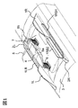
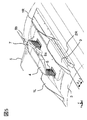
- FIGS. 1 to 4 are views showing a first embodiment of a sound insulation device for a moving vehicle according to the present invention, which are a perspective view, a front view, a left side view, and a right side view, respectively.
- a moving vehicle such as a railway vehicle traveling on a track is formed by connecting a plurality of vehicles, and is a current collector that is one of the rooftop installation devices on the roof 3 of a specific vehicle among the plurality of vehicles.
- the device is installed.
- a current collector is installed on the roof 3 of the moving vehicle.
- the current collector mainly includes an insulator 6 fixed to the roof 3 of the vehicle, a frame 4 supported by the insulator 6, a current collecting boat 5 that contacts the overhead line and collects current from the overhead line, and the current collecting boat.
- the arm 7 is configured to pivotally support the body 5 at the tip, and hinges 8a and 8b.
- the arm 7 is pivotally supported by a hinge 8 a having a rotation axis parallel to the vehicle body width direction with respect to the underframe 4, and by the joint function of the hinge 8 a and the hinge 8 b provided at the intermediate joint portion of the arm 7.
- the current collecting hull 5 can be folded into the non-operating position by folding downward, or it can be flipped upward to take the current collecting position.
- the insulator 6 is at a position offset from the center position in the vehicle body width direction by a predetermined distance toward one side.
- the left and right center position of the current collecting hull 5 and the positions where the arms 7 and the hinges 8a and 8b are disposed. Is approximately at the center in the vehicle width direction.
- the current collector hull 5 of the current collector is electrically connected to another current collector of the same train. Therefore, even if the current collecting hull 5 is in the non-operating position, if the other current collector is collecting current, the current collecting hull 5 is the current collecting boat of the other current collecting device. Charged to the same potential as the body.
- a sound insulator is installed at a position facing the current collector in the vehicle body width direction.
- the sound insulator is composed of a main sound insulator 1L and a lower sound insulator 2L on the left side in the vehicle traveling direction of the current collector.
- the sound insulation body 1L and the sound insulation body 2L are disposed at the same position in the vehicle body width direction, and a wall body continuous in the vehicle body longitudinal direction is divided and disposed.
- the sound insulator is composed of a tall main sound insulator 1R and a short sound insulator 2R.
- the sound insulation body 1R and the sound insulation body 2R are arranged at the same position in the vehicle body width direction, and a wall body continuous in the vehicle body longitudinal direction is divided and arranged.
- a sound insulator 1L is provided at a portion facing one insulator 6 in the vehicle traveling direction, and a sound insulator 1R is provided at a portion facing another insulator 6.
- the sound insulator 1L and the sound insulator 1R are wall bodies formed in a mountain shape along the vehicle traveling direction, and the height to the top of the wall is approximately the same as the height of the insulator 6. .
- the arrangement in the longitudinal direction of the vehicle body is opposite to that of the sound insulation body 1L and the sound insulation body 2L, and the sound insulation body 1L and the sound insulation body 1R do not overlap with the vehicle traveling direction when viewed from the side, in other words, the vehicle traveling direction. It is installed without substantially overlapping.
- the sound insulator 1L faces the sound insulator 2R
- the sound insulator 1R faces the sound insulator 2L.
- the sound insulating body 1L and the sound insulating body 1R can be accommodated within the vehicle limit range of the conventional line, and the portion exposed to the traveling wind becomes relatively small, and the sound insulating body 1L and the sound insulating body Aerodynamic noise generated from 1R can be reduced.
- the sound insulation effect can be enhanced by the installation of the sound insulation body 1L and the sound insulation body 1R having a simple configuration, and the sound insulation body having the maximum height within the vehicle limit range of the conventional line section. The insulation distance can be secured even with the use of and the sound insulation effect can be obtained.
- a short sound insulating body 2L provided on the roof 3 on one side (left side) in the vehicle body width direction includes a sound insulating body 1LB branched to the outside in the vehicle width direction.
- the arrangement relationship of the sound insulators at this time is such that the sound insulators 1L and 2L (not shown in the drawing because of the positional relationship) are erected, and the sound insulator 2L is outward in the vehicle width direction. It is arranged with the branched sound insulation 1LB.
- the short sound insulation body 2R provided on the roof 3 on the other side (right side) in the vehicle body width direction includes a sound insulation body 1RB1 branched to the outside in the vehicle body width direction and a sound insulation body 1RB2 branched to the inside in the width direction.
- the arrangement relationship of the sound insulators at this time is an arrangement of the sound insulator 1R and the sound insulator 2R to be erected, and the sound insulator 1RB1 and the sound insulator 1RB2 branched from the sound insulator 2R. .
- Fig. 3 shows the configuration as seen from the left.
- the sound insulator installed on the left side of the current collector is composed of a tall sound insulator 1L, a short sound insulator 2L, and a sound insulator 1LB branched from the sound insulator 2L.
- the branched sound insulation body 1LB is arranged so as to partially overlap the standing sound insulation body 1L and the sound insulation body 2L when viewed from the side.
- Fig. 4 shows the configuration viewed from the right.
- the sound insulator installed on the right side of the current collector is composed of a tall sound insulator 1R and a short sound insulator 2R, a sound insulator 1RB1 branched outward from the sound insulator 2R, and a sound insulator 1RB2 branched inward.
- the branched sound insulation body 1RB1 and sound insulation body 1RB2 are arranged such that a part of the sound insulation body 1R1 and the sound insulation body 1RB2 overlap each other with respect to the standing sound insulation body 1R and the sound insulation body 2R.
- the branched sound insulators 1LB, 1RB1 and 1RB2 extend obliquely upward from the upper sides of the sound insulator 2L and the sound insulator 2R, respectively. Further, as shown in FIGS. 1 and 3, the sound insulation body 1LB branched from the sound insulation body 2L extends in the longitudinal direction of the vehicle body across the middle position in the longitudinal direction of the sound insulation body 1L. Further, as shown in FIGS. 1 and 4, the sound insulation body 1RB1 branched from the sound insulation body 2R extends in the longitudinal direction of the vehicle body over the middle position in the longitudinal direction of the sound insulation body 1R.
- Aerodynamic noise generated from the current collector and its surroundings is blocked by the main sound insulation body and the sound insulation body having branched sound insulation bodies, and the reflected sound and diffracted sound are also reflected from the roof 3 to the outside of the vehicle body. It can be effectively prevented from propagating to the sound and sound insulation can be improved.
- the sound insulation body 1LB, the sound insulation body 1RB1, and the sound insulation body 1RB2 that are branched are arranged at positions that do not interfere with the vehicle limit and the insulation separation of the current collector in the conventional line section. Since the current collector is installed on the left side as shown in FIG. 2 with respect to the center of the vehicle, the sound insulator on the left side is provided with a sound insulator that branches inward in the sound insulator 2R due to the insulation separation of the current collector. However, from the viewpoint of the vehicle limit and the insulation separation of the current collector, it may be provided on the inner side or on both sides in the vehicle body width direction. In addition, the effect is recognized with only one of the sound insulators 1RB1 and 1RB2 branched from the right sound insulator.
- the sound insulation effect when provided outside the vehicle body width direction is large. Further, although the example of the sound insulation body that branches off is provided on the short sound insulation body and extends halfway to the tall sound insulation body, it may be extended to the full length of the tall sound insulation body.
- the configuration is simple and the sound insulation effect is high, and it is within the vehicle limit range of the conventional line section, and the insulation separation between the sound insulation body and the current collector is sufficiently provided. Can be secured.
- the sound insulation body sound insulation wall
- the height of the sound insulator is set lower than that of the conventional sound insulator.
- an insulation separation is also ensured between the sound insulator and the current collector.
- the branched sound insulators can suppress not only the direct sound but also the reflected sound from the opposing sound insulators and the diffracted sound that surrounds the sound insulators from propagating to the outside of the vehicle.
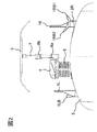
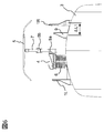
- Embodiment 2 of the present invention will be described with reference to FIGS. 5 to 8 are diagrams showing a second embodiment of the sound insulation device for a moving vehicle according to the present invention, and are a perspective view, a front view, a left side view, and a right side view, respectively.
- members having the same functions as those in the first embodiment are denoted by the same reference numerals, and detailed description thereof is omitted.
- the sound insulator is installed on the roof 3 of the moving vehicle so as to face each other with the installed current collecting device interposed therebetween.
- a main sound insulation body 1L and a lower sound insulation body 2L are arranged on the roof 3 in the same manner as in the first embodiment. There is no sound insulation that branches off.
- the main sound insulation body 1R and the lower sound insulation body 2R are arranged on the roof 3 in the same manner as in the first embodiment, but the sound insulation body 2R. There is no branching sound insulation.
- FIG. 6 shows a front view of this embodiment.
- the sound insulators are installed on both sides in the vehicle body width direction with the current collector interposed therebetween.
- the secondary sound insulator 9 is disposed between the sound insulator 1R and the sound insulator 2R (not shown in FIG. 6) and the current collector.
- the auxiliary sound insulator 9 has a height of the insulator 6 that is lower than the sound insulator 1R but higher than the sound insulator 2R.
- the overall shape of the auxiliary sound insulator 9 is a mountain shape similar to that of the sound insulator 1R. Have.
- the auxiliary sound insulating body 9 Since the aerodynamic noise is generated when the auxiliary sound insulating body 9 is installed at a position affected by the wake of the sound insulating body 1R and the sound insulating body 2R, the auxiliary sound insulating body 9 is sound-insulated at a position on the inner side in the vehicle width direction of the sound insulating body 2R. Although it is parallel to the body 2R, the sound insulation body 1R and the sound insulation body 2R are installed at a distance ( ⁇ L1) that is about twice as large as the vehicle body width direction thickness. In the configuration of the present embodiment, since the current collector is installed offset to the left side with respect to the vehicle center, the installation position of the sub sound insulator 9 ensures an insulation separation with respect to the high voltage portion of the current collector. Is in position. On the other hand, between the current collector and the sound insulation body 1L and the sound insulation body 2L, a secondary sound insulation body cannot be installed due to the insulation separation from the current collecting boat body 5 with the arm 7 folded.
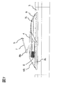
- FIG. 7 shows a view of the present configuration from the left
- FIG. 8 shows a view of the present configuration from the right
- the secondary sound insulator 9 is disposed at a position shifted from the right sound insulator 1R and the sound insulator 2R.
- the secondary sound insulator 9 is subordinate to the sound insulator 1R and the sound insulator 2R as viewed from the side.
- the sound insulators 9 are arranged so that their areas partially overlap.
- a range where the sound insulation body 1R and the sub sound insulation body 9 overlap in the longitudinal direction of the vehicle body is indicated by ⁇ L2. Since this range ⁇ L2 is an overlap of the mountain-shaped hem portion of the sound insulator 1R and the sub-insulator 9, the height is low, and the current collecting hull 5 when the arm 7 is folded is reduced. Insulating separation can be secured.
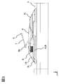
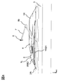
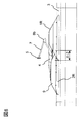
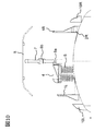
- Embodiment 3 of the present invention will be described with reference to FIGS. 9 to 12 are diagrams showing a third embodiment of the sound insulation device for a moving vehicle according to the present invention, and are a perspective view, a front view, a left side view, and a right side view, respectively.
- members having the same functions as those of the first embodiment are denoted by the same reference numerals, and detailed description thereof is omitted.
- the sound insulator is installed on the roof 3 of the moving vehicle so as to face each other with the installed current collecting device interposed therebetween.
- FIG. 9 to 12 are diagrams showing a third embodiment of the sound insulation device for a moving vehicle according to the present invention, and are a perspective view, a front view, a left side view, and a right side view, respectively.
- members having the same functions as those of the first embodiment are denoted by the same reference numerals, and detailed description thereof is omitted.
- the sound insulator is installed on the roof 3 of the moving vehicle so as to face each
- the secondary sound insulation body 10L is disposed on the outer side in the vehicle width direction of the left sound insulation body 1L and the sound insulation body 2L, and the right sound insulation body 1R and the sound insulation body 2R.
- a secondary sound insulator 10R is disposed on the outer side in the vehicle body width direction.
- FIG. 10 shows a front view of this configuration.
- the sound insulators 1R and 2R and the sound insulators 1L and 2L are installed on both sides in the vehicle body width direction with the current collector interposed therebetween.
- the secondary sound insulation body 10R is disposed on the outer side in the vehicle width direction of the sound insulation body 1R and the sound insulation body 2R installed on the right side of the current collector, while the sound insulation body 1L and the sound insulation body are disposed on the left side of the current collection apparatus.
- a secondary sound insulator 10L is installed outside 2L.
- the heights of the sub sound insulators 10L and 10R are approximately the same as the height of the sound insulator 2L and the sound insulator 2R, respectively, and as a whole, both ends in the longitudinal direction of the vehicle body are the sound insulator 2L and the sound insulator. It has a low chevron shape having the same shape as the end of the body 2R. As in the case of the second embodiment, since the aerodynamic noise may occur when the distance between the sound insulation body and the sub sound insulation body is small, the sub sound insulation bodies 10L and 10R are arranged in the vehicle width direction of the sound insulation bodies 2L and 2R.
- the auxiliary sound insulators 10L and 10R extend in the longitudinal direction of the vehicle body in the longitudinal direction of the vehicle body to positions corresponding to the middle positions of the sound insulating body 1L and the sound insulating body 2L.
- the sub sound insulation bodies 10L and 10R are installed on the outside of the sound insulation bodies 1L and 2L and the sound insulation bodies 1R and 2R in the vehicle width direction, so that the sub sound insulation bodies 10L and 10R can be placed within the vehicle limit range in the conventional line section. However, it is a position where an insulation separation is naturally secured for the high voltage part of the current collector.
- FIG. 11 shows a view of the present configuration from the left
- FIG. 12 shows a view of the present configuration from the right.
- the secondary sound insulator 10L is generally within the range shielded by the sound insulator 1L and the sound insulator 2L when viewed from the side with respect to the left sound insulator 1L and the sound insulator 2L.
- the auxiliary sound insulator 10R has a height level slightly higher than that of the sound insulator 2R with respect to the right sound insulator 1R and the sound insulator 2R.
- the sound insulator 1R and the sound insulator 2R are arranged so as to cover the open space above the overlapping skirt (range ⁇ L2 shown in FIG. 8 of Example 2).
- the secondary sound insulator 10R contributes to preventing noise leakage through this space. Since the secondary sound insulator 10R is disposed on the outer side in the vehicle width direction of the right sound insulator 1R and the sound insulator 2R, an insulation separation is ensured with respect to the current collecting boat body 5 when the arm 7 of the current collector is folded. can do.
- the present invention has been described by taking a railway vehicle as an example of a moving vehicle.
- the present invention is not limited to this, and can be applied to a vehicle that travels at high speed and generates noise from a device provided on a roof such as a current collector. it can.
- the sub sound insulation body 9 and the sub sound insulation bodies 10L and 10R have been described separately, but both sub sound insulation bodies may be provided as long as each constraint such as a space is satisfied.
Landscapes
- Engineering & Computer Science (AREA)
- Mechanical Engineering (AREA)
- Physics & Mathematics (AREA)
- Transportation (AREA)
- Acoustics & Sound (AREA)
- Power Engineering (AREA)
- Multimedia (AREA)
- Chemical & Material Sciences (AREA)
- Combustion & Propulsion (AREA)
- Fluid Mechanics (AREA)
- Aviation & Aerospace Engineering (AREA)
- Current-Collector Devices For Electrically Propelled Vehicles (AREA)
- Vehicle Interior And Exterior Ornaments, Soundproofing, And Insulation (AREA)
Priority Applications (2)
| Application Number | Priority Date | Filing Date | Title |
|---|---|---|---|
| GB1321016.6A GB2505795B (en) | 2011-05-31 | 2012-05-25 | Acoustic insulation device for mobile vehicle |
| US14/123,132 US9227577B2 (en) | 2011-05-31 | 2012-05-25 | Acoustic insulation device for mobile vehicle |
Applications Claiming Priority (2)
| Application Number | Priority Date | Filing Date | Title |
|---|---|---|---|
| JP2011121706A JP6185219B2 (ja) | 2011-05-31 | 2011-05-31 | 移動車両用遮音装置 |
| JP2011-121706 | 2011-05-31 |
Publications (1)
| Publication Number | Publication Date |
|---|---|
| WO2012165331A1 true WO2012165331A1 (ja) | 2012-12-06 |
Family
ID=47259188
Family Applications (1)
| Application Number | Title | Priority Date | Filing Date |
|---|---|---|---|
| PCT/JP2012/063483 Ceased WO2012165331A1 (ja) | 2011-05-31 | 2012-05-25 | 移動車両用遮音装置 |
Country Status (4)
| Country | Link |
|---|---|
| US (1) | US9227577B2 (enExample) |
| JP (1) | JP6185219B2 (enExample) |
| GB (1) | GB2505795B (enExample) |
| WO (1) | WO2012165331A1 (enExample) |
Families Citing this family (4)
| Publication number | Priority date | Publication date | Assignee | Title |
|---|---|---|---|---|
| DE102012202955A1 (de) * | 2012-02-27 | 2013-08-29 | Schunk Bahn- Und Industrietechnik Gmbh | Stromübertragungsvorrichtung zur Aufladung elektrischer Energiespeicher von Fahrzeugen an Überkopfladestationen |
| CN104149632B (zh) * | 2014-08-19 | 2016-03-16 | 安徽理工大学 | 三自由度混联减振受电弓 |
| CN110126625B (zh) * | 2019-05-16 | 2021-08-31 | 大连交通大学 | 一种新型高速受电弓及其轻量化动态设计方法 |
| CN110182148B (zh) * | 2019-06-10 | 2022-08-23 | 惠州市惠福鞋材有限公司 | 一种汽车用隔音eva板材 |
Citations (6)
| Publication number | Priority date | Publication date | Assignee | Title |
|---|---|---|---|---|
| JPH0480203U (enExample) * | 1990-11-20 | 1992-07-13 | ||
| JPH0885921A (ja) * | 1994-07-20 | 1996-04-02 | Bridgestone Corp | 防音壁 |
| JPH0898306A (ja) * | 1994-09-16 | 1996-04-12 | West Japan Railway Co | 集電装置の防風カバー |
| JP2001034272A (ja) * | 1999-07-19 | 2001-02-09 | Biiba Kk | 消音装置 |
| JP2006159938A (ja) * | 2004-12-02 | 2006-06-22 | East Japan Railway Co | 車両用集電装置の遮音板 |
| JP2009179191A (ja) * | 2008-01-31 | 2009-08-13 | Hitachi Ltd | 移動車両用遮音装置 |
Family Cites Families (6)
| Publication number | Priority date | Publication date | Assignee | Title |
|---|---|---|---|---|
| JP2938159B2 (ja) | 1990-07-20 | 1999-08-23 | 三井化学株式会社 | 高光沢耐衝撃性ゴム変性樹脂の連続的製造方法 |
| JPH0577729A (ja) * | 1991-03-29 | 1993-03-30 | Hitachi Ltd | 車両の遮音装置 |
| JP2003219505A (ja) * | 2002-01-22 | 2003-07-31 | Central Japan Railway Co | パンタグラフカバー装置の吸音側壁構造 |
| JP3908214B2 (ja) * | 2003-10-28 | 2007-04-25 | 近畿車輌株式会社 | 集電装置の防音側壁 |
| JP4286759B2 (ja) * | 2004-10-01 | 2009-07-01 | 東海旅客鉄道株式会社 | 車両の屋上突起物類のカバー装置 |
| JP5215708B2 (ja) * | 2008-03-31 | 2013-06-19 | 株式会社日立製作所 | 集電装置用防音側壁、およびそれを備えた鉄道車両 |
-
2011
- 2011-05-31 JP JP2011121706A patent/JP6185219B2/ja active Active
-
2012
- 2012-05-25 WO PCT/JP2012/063483 patent/WO2012165331A1/ja not_active Ceased
- 2012-05-25 GB GB1321016.6A patent/GB2505795B/en not_active Expired - Fee Related
- 2012-05-25 US US14/123,132 patent/US9227577B2/en active Active
Patent Citations (6)
| Publication number | Priority date | Publication date | Assignee | Title |
|---|---|---|---|---|
| JPH0480203U (enExample) * | 1990-11-20 | 1992-07-13 | ||
| JPH0885921A (ja) * | 1994-07-20 | 1996-04-02 | Bridgestone Corp | 防音壁 |
| JPH0898306A (ja) * | 1994-09-16 | 1996-04-12 | West Japan Railway Co | 集電装置の防風カバー |
| JP2001034272A (ja) * | 1999-07-19 | 2001-02-09 | Biiba Kk | 消音装置 |
| JP2006159938A (ja) * | 2004-12-02 | 2006-06-22 | East Japan Railway Co | 車両用集電装置の遮音板 |
| JP2009179191A (ja) * | 2008-01-31 | 2009-08-13 | Hitachi Ltd | 移動車両用遮音装置 |
Also Published As
| Publication number | Publication date |
|---|---|
| GB2505795A (en) | 2014-03-12 |
| GB2505795B (en) | 2017-03-15 |
| GB201321016D0 (en) | 2014-01-15 |
| JP6185219B2 (ja) | 2017-08-23 |
| US20140203596A1 (en) | 2014-07-24 |
| JP2012249493A (ja) | 2012-12-13 |
| US9227577B2 (en) | 2016-01-05 |
Similar Documents
| Publication | Publication Date | Title |
|---|---|---|
| JP6185219B2 (ja) | 移動車両用遮音装置 | |
| JP2005282276A (ja) | 鉄道用防音装置 | |
| JP5189374B2 (ja) | 移動車両用遮音装置 | |
| JP3374469B2 (ja) | 集電装置 | |
| JP2004132062A (ja) | 鉄道用防音壁 | |
| JP2012116279A (ja) | ジャバラ式カバー付きパンタグラフ | |
| JP2012249493A5 (enExample) | ||
| JP2007176192A (ja) | 鉄道車両の遮音壁 | |
| CN101654083B (zh) | 具备吸音结构的轨道车辆 | |
| JP3069828B2 (ja) | 集電装置の防風カバー | |
| JP3678949B2 (ja) | 移動音源用可視型防音壁 | |
| JP2005030116A (ja) | 移動音源用可視型防音壁及び防音ユニット | |
| CN223443551U (zh) | 一种分体式布局轨道检测设备 | |
| JP2006159938A (ja) | 車両用集電装置の遮音板 | |
| JPH0742163Y2 (ja) | 列車屋上機器の騒音防止構造 | |
| JP4997296B2 (ja) | 整流カバー | |
| JP4329051B2 (ja) | 集電装置の防風カバー | |
| JPH0270804A (ja) | 跨座型モノレール車両用騒音制御装置 | |
| JP2009165211A (ja) | 車両の騒音低減装置 | |
| JP3045029B2 (ja) | 防音壁 | |
| JP3765609B2 (ja) | 遮音壁 | |
| KR100443940B1 (ko) | 콘크리트 철도 건널목용 방음 저진판 | |
| JPH0386001A (ja) | パンタグラフの騒音低減装置 | |
| JP2004257230A (ja) | 固定構造物の通過波低減構造 | |
| JP2001026267A (ja) | 鉄道車両 |
Legal Events
| Date | Code | Title | Description |
|---|---|---|---|
| 121 | Ep: the epo has been informed by wipo that ep was designated in this application |
Ref document number: 12792576 Country of ref document: EP Kind code of ref document: A1 |
|
| ENP | Entry into the national phase |
Ref document number: 1321016 Country of ref document: GB Kind code of ref document: A Free format text: PCT FILING DATE = 20120525 |
|
| WWE | Wipo information: entry into national phase |
Ref document number: 1321016.6 Country of ref document: GB |
|
| NENP | Non-entry into the national phase |
Ref country code: DE |
|
| WWE | Wipo information: entry into national phase |
Ref document number: 14123132 Country of ref document: US |
|
| 122 | Ep: pct application non-entry in european phase |
Ref document number: 12792576 Country of ref document: EP Kind code of ref document: A1 |