WO2012165170A1 - 太陽電池用裏面保護シートとそれを備えた太陽電池モジュール - Google Patents
太陽電池用裏面保護シートとそれを備えた太陽電池モジュール Download PDFInfo
- Publication number
- WO2012165170A1 WO2012165170A1 PCT/JP2012/062740 JP2012062740W WO2012165170A1 WO 2012165170 A1 WO2012165170 A1 WO 2012165170A1 JP 2012062740 W JP2012062740 W JP 2012062740W WO 2012165170 A1 WO2012165170 A1 WO 2012165170A1
- Authority
- WO
- WIPO (PCT)
- Prior art keywords
- resin layer
- solar cell
- back surface
- cell module
- film
- Prior art date
- Legal status (The legal status is an assumption and is not a legal conclusion. Google has not performed a legal analysis and makes no representation as to the accuracy of the status listed.)
- Ceased
Links
Images
Classifications
-
- B—PERFORMING OPERATIONS; TRANSPORTING
- B32—LAYERED PRODUCTS
- B32B—LAYERED PRODUCTS, i.e. PRODUCTS BUILT-UP OF STRATA OF FLAT OR NON-FLAT, e.g. CELLULAR OR HONEYCOMB, FORM
- B32B27/00—Layered products comprising a layer of synthetic resin
- B32B27/40—Layered products comprising a layer of synthetic resin comprising polyurethanes
-
- B—PERFORMING OPERATIONS; TRANSPORTING
- B32—LAYERED PRODUCTS
- B32B—LAYERED PRODUCTS, i.e. PRODUCTS BUILT-UP OF STRATA OF FLAT OR NON-FLAT, e.g. CELLULAR OR HONEYCOMB, FORM
- B32B27/00—Layered products comprising a layer of synthetic resin
- B32B27/06—Layered products comprising a layer of synthetic resin as the main or only constituent of a layer, which is next to another layer of the same or of a different material
- B32B27/08—Layered products comprising a layer of synthetic resin as the main or only constituent of a layer, which is next to another layer of the same or of a different material of synthetic resin
-
- B—PERFORMING OPERATIONS; TRANSPORTING
- B32—LAYERED PRODUCTS
- B32B—LAYERED PRODUCTS, i.e. PRODUCTS BUILT-UP OF STRATA OF FLAT OR NON-FLAT, e.g. CELLULAR OR HONEYCOMB, FORM
- B32B27/00—Layered products comprising a layer of synthetic resin
- B32B27/18—Layered products comprising a layer of synthetic resin characterised by the use of special additives
- B32B27/20—Layered products comprising a layer of synthetic resin characterised by the use of special additives using fillers, pigments, thixotroping agents
-
- B—PERFORMING OPERATIONS; TRANSPORTING
- B32—LAYERED PRODUCTS
- B32B—LAYERED PRODUCTS, i.e. PRODUCTS BUILT-UP OF STRATA OF FLAT OR NON-FLAT, e.g. CELLULAR OR HONEYCOMB, FORM
- B32B27/00—Layered products comprising a layer of synthetic resin
- B32B27/30—Layered products comprising a layer of synthetic resin comprising vinyl (co)polymers; comprising acrylic (co)polymers
- B32B27/304—Layered products comprising a layer of synthetic resin comprising vinyl (co)polymers; comprising acrylic (co)polymers comprising vinyl halide (co)polymers, e.g. PVC, PVDC, PVF, PVDF
-
- B—PERFORMING OPERATIONS; TRANSPORTING
- B32—LAYERED PRODUCTS
- B32B—LAYERED PRODUCTS, i.e. PRODUCTS BUILT-UP OF STRATA OF FLAT OR NON-FLAT, e.g. CELLULAR OR HONEYCOMB, FORM
- B32B27/00—Layered products comprising a layer of synthetic resin
- B32B27/32—Layered products comprising a layer of synthetic resin comprising polyolefins
-
- B—PERFORMING OPERATIONS; TRANSPORTING
- B32—LAYERED PRODUCTS
- B32B—LAYERED PRODUCTS, i.e. PRODUCTS BUILT-UP OF STRATA OF FLAT OR NON-FLAT, e.g. CELLULAR OR HONEYCOMB, FORM
- B32B27/00—Layered products comprising a layer of synthetic resin
- B32B27/32—Layered products comprising a layer of synthetic resin comprising polyolefins
- B32B27/322—Layered products comprising a layer of synthetic resin comprising polyolefins comprising halogenated polyolefins, e.g. PTFE
-
- B—PERFORMING OPERATIONS; TRANSPORTING
- B32—LAYERED PRODUCTS
- B32B—LAYERED PRODUCTS, i.e. PRODUCTS BUILT-UP OF STRATA OF FLAT OR NON-FLAT, e.g. CELLULAR OR HONEYCOMB, FORM
- B32B7/00—Layered products characterised by the relation between layers; Layered products characterised by the relative orientation of features between layers, or by the relative values of a measurable parameter between layers, i.e. products comprising layers having different physical, chemical or physicochemical properties; Layered products characterised by the interconnection of layers
- B32B7/04—Interconnection of layers
- B32B7/12—Interconnection of layers using interposed adhesives or interposed materials with bonding properties
-
- H—ELECTRICITY
- H10—SEMICONDUCTOR DEVICES; ELECTRIC SOLID-STATE DEVICES NOT OTHERWISE PROVIDED FOR
- H10F—INORGANIC SEMICONDUCTOR DEVICES SENSITIVE TO INFRARED RADIATION, LIGHT, ELECTROMAGNETIC RADIATION OF SHORTER WAVELENGTH OR CORPUSCULAR RADIATION
- H10F19/00—Integrated devices, or assemblies of multiple devices, comprising at least one photovoltaic cell covered by group H10F10/00, e.g. photovoltaic modules
- H10F19/80—Encapsulations or containers for integrated devices, or assemblies of multiple devices, having photovoltaic cells
- H10F19/85—Protective back sheets
-
- B—PERFORMING OPERATIONS; TRANSPORTING
- B32—LAYERED PRODUCTS
- B32B—LAYERED PRODUCTS, i.e. PRODUCTS BUILT-UP OF STRATA OF FLAT OR NON-FLAT, e.g. CELLULAR OR HONEYCOMB, FORM
- B32B2264/00—Composition or properties of particles which form a particulate layer or are present as additives
- B32B2264/10—Inorganic particles
- B32B2264/102—Oxide or hydroxide
-
- B—PERFORMING OPERATIONS; TRANSPORTING
- B32—LAYERED PRODUCTS
- B32B—LAYERED PRODUCTS, i.e. PRODUCTS BUILT-UP OF STRATA OF FLAT OR NON-FLAT, e.g. CELLULAR OR HONEYCOMB, FORM
- B32B2307/00—Properties of the layers or laminate
- B32B2307/30—Properties of the layers or laminate having particular thermal properties
- B32B2307/306—Resistant to heat
-
- B—PERFORMING OPERATIONS; TRANSPORTING
- B32—LAYERED PRODUCTS
- B32B—LAYERED PRODUCTS, i.e. PRODUCTS BUILT-UP OF STRATA OF FLAT OR NON-FLAT, e.g. CELLULAR OR HONEYCOMB, FORM
- B32B2307/00—Properties of the layers or laminate
- B32B2307/40—Properties of the layers or laminate having particular optical properties
- B32B2307/412—Transparent
-
- B—PERFORMING OPERATIONS; TRANSPORTING
- B32—LAYERED PRODUCTS
- B32B—LAYERED PRODUCTS, i.e. PRODUCTS BUILT-UP OF STRATA OF FLAT OR NON-FLAT, e.g. CELLULAR OR HONEYCOMB, FORM
- B32B2307/00—Properties of the layers or laminate
- B32B2307/70—Other properties
- B32B2307/712—Weather resistant
-
- B—PERFORMING OPERATIONS; TRANSPORTING
- B32—LAYERED PRODUCTS
- B32B—LAYERED PRODUCTS, i.e. PRODUCTS BUILT-UP OF STRATA OF FLAT OR NON-FLAT, e.g. CELLULAR OR HONEYCOMB, FORM
- B32B2457/00—Electrical equipment
-
- Y—GENERAL TAGGING OF NEW TECHNOLOGICAL DEVELOPMENTS; GENERAL TAGGING OF CROSS-SECTIONAL TECHNOLOGIES SPANNING OVER SEVERAL SECTIONS OF THE IPC; TECHNICAL SUBJECTS COVERED BY FORMER USPC CROSS-REFERENCE ART COLLECTIONS [XRACs] AND DIGESTS
- Y02—TECHNOLOGIES OR APPLICATIONS FOR MITIGATION OR ADAPTATION AGAINST CLIMATE CHANGE
- Y02E—REDUCTION OF GREENHOUSE GAS [GHG] EMISSIONS, RELATED TO ENERGY GENERATION, TRANSMISSION OR DISTRIBUTION
- Y02E10/00—Energy generation through renewable energy sources
- Y02E10/50—Photovoltaic [PV] energy
Definitions
- the present invention relates to a solar cell back surface protective sheet disposed on the back surface side of a solar cell module and a solar cell module including the solar cell module, and specifically, a solar cell back surface protective sheet having long-term weather resistance and the solar cell module.
- the present invention relates to a solar cell module.
- a transparent glass plate is disposed on the front surface side and the back surface side is a resin as a solar cell back surface protection sheet for the purpose of protecting the solar cell elements, electrodes, wiring, and the like.
- a laminated sheet of film is placed.
- the solar cell element is sealed with a filler such as ethylene-vinyl acetate copolymer (EVA) resin, and is disposed so as to be sandwiched between the transparent glass plate on the front surface side and the laminated sheet on the back surface side.
- EVA ethylene-vinyl acetate copolymer
- the back surface protection sheet for solar cells is bonded to the outer surface of the EVA resin by a hot press.
- the back surface protection sheet for solar cells is provided with an adhesive resin film (adhesive layer) on the side to be bonded to EVA and a weather resistant film (weather resistant layer) on the side exposed to the outside air. ing. Furthermore, in order to prevent vapor, moisture, etc. from the outside air from reaching the solar cell element, a moisture-permeable film (moisture-resistant layer) is disposed between the adhesive layer and the weather-resistant layer.
- a moisture-permeable film moisture-resistant layer
- Patent Document 1 proposes a back protective sheet for solar cells that includes a polyethylene terephthalate (PET) film as a moisture-permeable layer.
- the back surface protection sheet for solar cells described in Patent Document 1 is such that PET as a moisture permeable layer is hydrolyzed by ultraviolet light and moisture in the atmosphere during use in the open air, and the adhesive layer and weather resistance are used over a long period of use. There was a problem that the adhesiveness with the adhesive layer was lowered.
- the object of the present invention has been made in view of the above-described problems, and a solar cell back surface protective sheet capable of improving long-term adhesion between layers constituting the solar cell back surface protective sheet and the same. It is providing the solar cell module provided.
- the back surface protection sheet for solar cells is a back surface protection sheet for solar cells arrange
- the back surface protection sheet for solar cells of the present invention by using unstretched polypropylene that does not cause hydrolysis in the second resin layer, between the first resin layer and the second resin layer, and second High adhesiveness can be maintained for a long time between the resin layer and the third resin layer.
- the second resin layer is a first film made of an unstretched polypropylene film exhibiting white color or an unstretched polypropylene film exhibiting colorless transparency, and both surfaces of the first film. And a second film made of an unstretched polypropylene film exhibiting colorless and transparent.
- the second resin layer is formed between the first resin layer and the third resin layer so that the surface roughness or the like generated during the production of the unstretched polypropylene film is not noticeable. It can be laminated with a gap therebetween.
- the second resin layer contains titanium oxide.
- the second resin layer can have a function of absorbing or reflecting ultraviolet rays.
- the first resin layer contains linear low density polyethylene
- the third resin layer is made of polyvinylidene fluoride, polyvinyl fluoride, and ethylene tetrafluoroethylene. It is preferable to include at least one more selected.
- the first resin layer and the second resin layer and / or the second resin layer and the third resin layer interpose a urethane adhesive layer. It is preferable that they are fixed.
- the first resin layer is disposed on the filler disposed for sealing the solar cell element and the outer surface of the charging material on the back surface side of the solar cell module.
- a back surface protection sheet for solar cells having the above-described characteristics, which are fixed in such a manner.
- the second resin layer and the third resin layer are provided between the first resin layer and the second resin layer. Since high adhesiveness can be maintained for a long time between the resin layers, the long-term weather resistance of the back surface protection sheet for solar cells and the solar cell module including the same can be improved.
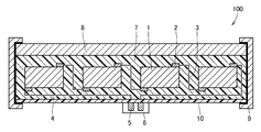
- a large number of solar cell elements 1 are arranged in the solar cell module 100. These solar cell elements 1 are electrically connected to each other through connection wires 3 via electrodes 2, and the solar cell module 100 as a whole has a terminal 5 taken out on the back side by a lead wire 4, and the terminal 5 is a terminal box 6. It is stored in.
- a filler 7 made of an ethylene-vinyl acetate copolymer (EVA) resin or the like is arranged to seal a large number of solar cell elements 1.
- EVA ethylene-vinyl acetate copolymer
- a transparent glass layer 8 is fixed to the outer surface of the filler 7 located on the light receiving surface side of the solar cell module 100.
- the back surface protection sheet 10 for solar cells of this invention is adhering to the outer surface of the filler 7 located in the installation surface side of a solar cell module.
- An aluminum frame member 9 is attached to the side surface of the solar cell module 100 via a sealing material.
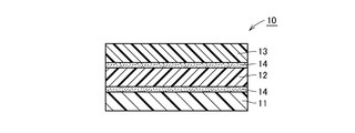
- the solar cell back surface protection sheet 10 includes a first resin layer 11, a second resin layer 2, and a second resin layer 11. It is comprised from the laminated body laminated
- the second resin layer 12 As the material of the second resin layer 12, unstretched polypropylene is used. Since unstretched polypropylene does not undergo hydrolysis due to ultraviolet rays, moisture in the air, etc., it can have high adhesion with the first resin layer 11 in the long term.
- the second resin layer 12 may be an unstretched polypropylene film exhibiting colorless transparency or an unstretched polypropylene film exhibiting white.
- the second resin layer 12 may be configured by laminating an unstretched polypropylene film exhibiting colorless and transparent on both surfaces of an unstretched polypropylene film exhibiting white or an unstretched polypropylene film exhibiting colorless and transparent. preferable. In this case, the second resin layer 12 is laminated between the first resin layer 11 and the third resin layer 13 so that the surface roughness or the like generated during the production of the unstretched polypropylene film is not noticeable. Can do.
- the material of the first resin layer 11 and the third resin layer 13 is not particularly limited.
- PE polyethylene
- LLDPE linear low density polyethylene
- PP polypropylene
- Polyolefin resins such as polybutene, (meth) acrylic resins, polyvinyl chloride resins, polystyrene resins, polyvinylidene chloride resins, saponified ethylene-vinyl acetate copolymers, polyvinyl alcohol, polycarbonate resins, fluorine Resin (polyvinylidene fluoride, polyvinyl fluoride, ethylene tetrafluoroethylene), polyvinyl acetate resin, acetal resin, polyester resin (polyethylene terephthalate (PET), polybutylene terephthalate, polyethylene naphthalate), polyamid A film or sheet of a resin or other various resins can be used.
- PET polyethylene terephthalate
- PET polybutylene terephthalate
- the first resin layer 11 includes linear low density polyethylene
- the third resin layer 13 includes one or two selected from polyvinylidene fluoride, polyvinyl fluoride (PVF), and ethylene tetrafluoroethylene. preferable. In this case, high adhesion between the first resin layer 11 and the second resin layer 12 and between the second resin layer 12 and the third resin layer 13 is maintained for a long time. Can do.
- the lamination method in each of the 1st resin layer 11 and the 2nd resin layer 12, and the 2nd resin layer 12 and the 3rd resin layer 13 should just use a well-known method, for example, 2 liquid curing type Uses dry lamination method, co-extrusion method, extrusion coating method, anchor coating agent using urethane adhesive, polyether urethane adhesive, polyester adhesive, polyester polyol adhesive, polyester polyurethane polyol adhesive, etc. It is possible to adopt a method such as a heat laminating method. In particular, a dry laminating method using a urethane-based adhesive containing at least one kind of aromatic isocyanate or aliphatic isocyanate can be suitably employed.
- the second resin layer 12 may be mixed with a white pigment such as titanium oxide or barium sulfate, or a black pigment such as carbon.
- a white pigment such as titanium oxide or barium sulfate
- a black pigment such as carbon
- known additives such as known UV absorbers, moisture absorbers (drying agents), oxygen absorbers, antioxidants and the like other than the color pigments may be added to at least one of the first resin layer 11 and the third resin layer 13. It can also be mixed in crab.
- the first resin layer 11 is laminated on the surface on the solar cell module 100 (power generation cell) side.
- the thickness of the first resin layer 11 is preferably 50 ⁇ m or more and 300 ⁇ m or less, and more preferably 125 ⁇ m or more and 250 ⁇ m or less. If the thickness of the first resin layer 11 is less than 50 ⁇ m, the insulation between the solar cell module 100 (power generation cell) and the second resin layer 12 is not sufficient. Moreover, when the thickness of the 1st resin layer 11 exceeds 300 micrometers, insulation will be saturated, the weight of the back surface protection sheet 10 for solar cell modules will become heavy, or a softness
- the surface of the first resin layer 11 on the solar cell module 100 (power generation cell) side is improved in adhesion to the filler 7 (FIG. 1) made of ethylene-vinyl acetate copolymer (EVA) resin or the like.
- a primer layer may be formed.
- the primer agent it is preferable to use an acrylic primer, a polyester primer or the like.
- the application amount of the primer agent may be about 2 to 15 g / m 2 .
- the second resin layer 12 is laminated on the surface of the first resin layer 11 opposite to the solar cell module 100 (power generation cell) side.
- the thickness of the second resin layer 12 is preferably 20 ⁇ m or more and 200 ⁇ m or less, and more preferably 20 ⁇ m or more and 50 ⁇ m or less.
- the second resin layer 12 includes at least one layer of colorless, transparent or white unstretched polypropylene. When the thickness of the second resin layer 12 is less than 20 ⁇ m, the weather resistance is not sufficient.
- the thickness of the 2nd resin layer 12 exceeds 200 micrometers, a weather resistance will be saturated, the weight of the back surface protection sheet 10 for solar cell modules will become heavy, or a softness
- flexibility will be impaired.
- a white film colored with a titanium oxide pigment or a barium sulfate pigment is preferably used.
- Example 1 A linear low density polyethylene resin composition is prepared by adding 25 kg of titanium oxide particles having an average particle diameter of 0.3 ⁇ m to 100 kg of polyethylene resin (manufactured by Tamapoly Co., Ltd.) having a density of 0.91 g / cm 3 and thoroughly kneading. Prepared. By extruding this linear low density polyethylene resin composition with an extruder, a first film having a thickness of 50 ⁇ m was produced as a film constituting the first resin layer 11.
- unstretched polypropylene manufactured by Mitsubishi Plastics Co., Ltd.
- a second film having a thickness of 200 ⁇ m was produced as a film constituting the second resin layer 12.
- White unstretched polypropylene was obtained by mixing 25 kg of titanium oxide particles having an average particle diameter of 0.3 ⁇ m with 100 kg of colorless and transparent unstretched polypropylene.
- a polyvinyl fluoride film (manufactured by DuPont) having a thickness of 38 ⁇ m was prepared as a third film constituting the third resin layer 13. With these films, the first film is placed on one side of the second film and the third film is placed on the other side, and a dry laminating adhesive is interposed between each film. And the back surface protection sheet 10 for solar cells was produced by making it adhere
- an adhesive for dry lamination a polyurethane-based adhesive in which a product name Takerak A315 (100 parts by weight) manufactured by Mitsui Chemicals, Inc. and a product name Takenate A50 (10 parts by weight) are mixed has a solid coating amount. It was prepared and used so that it might become 5 g / m ⁇ 2 >.
- Example 2 By overlaying unstretched polypropylene (manufactured by Mitsubishi Plastics Co., Ltd.) that is colorless and transparent, colorless and transparent, and colorless and transparent in order, and co-extruding with a T-die extruder so that the thickness ratio is 1: 8: 1
- a solar cell back surface protective sheet 10 was produced in the same manner as in Example 1 except that a second film having a thickness of 200 ⁇ m was produced as a film constituting the second resin layer 12.
- Example 1 A polyester film (made by Toyobo Co., Ltd.) having a thickness of 250 ⁇ m was prepared as the second film, and a polyvinyl fluoride film (made by DuPont) having a thickness of 38 ⁇ m was prepared as the first and third films.
- a solar cell back surface protective sheet 10 was produced by interposing a dry laminating adhesive between the respective films and adhering them by a dry laminating method.
- Comparative Example 2 A solar cell back surface protective sheet 10 was produced in the same manner as in Comparative Example 1 except that the first film of Example 1 was used as the first film.
- Comparative Example 3 As a third film, an adhesive for dry lamination is interposed between a silica-deposited polyester film having a thickness of 12 ⁇ m (manufactured by Mitsubishi Plastics) and a polyvinyl fluoride film having a thickness of 38 ⁇ m (manufactured by DuPont).
- a solar cell back surface protective sheet 10 was produced in the same manner as in Comparative Example 2, except that the second film and the third film were adhered to the silica-deposited polyester film side by adhering by a laminating method. .
- the total thickness, tensile strength retention rate, tensile elongation retention rate, change in moisture permeability, partial discharge voltage are as follows. The reflectance was measured.
- Total thickness The actual thickness [ ⁇ m] of the manufactured solar cell back surface protective sheet 10 was measured with a micro gauge.
- the tensile strength retention rate and the tensile elongation retention rate are evaluated by performing a pressure cooker test as an environmental promotion test in an atmosphere of a temperature of 120 ° C., a relative humidity of 100% RH, and 2 atmospheres. It is a thing.
- Moisture permeability was measured immediately after sample preparation (initial stage) and after holding for 100 hours under pressure cooker test (PCT) (test conditions: temperature 120 ° C., relative humidity 100% RH, 2 atm).
- Reflectance Using a multi-purpose spectrophotometer manufactured by JASCO Corporation, the transmittance in the wavelength range of 200 to 2000 nm was measured, and the reflectance [%] at 550 nm was evaluated as the light reflectance.
- the solar cell back surface protective sheet of the present invention is disposed and used on the back surface side of the solar cell module, and can maintain the weather resistance over a long period of time.
Landscapes
- Photovoltaic Devices (AREA)
Abstract
太陽電池素子を封止するために用いられる充填材としてのEVA樹脂との密着性を高めることができ、長期間にわたって耐候性を維持することが可能な太陽電池用裏面保護シートとそれを備えた太陽電池モジュールを提供する。太陽電池モジュールの裏面側に配置される太陽電池用裏面保護シート(10)は、順に積層された第1の樹脂層(11)、第2の樹脂層(12)、および、第3の樹脂層(13)を備え、第2の樹脂層(12)が無延伸ポリプロピレンを含む。太陽電池モジュールは、太陽電池素子を封止するために配置された充填材と、太陽電池モジュールの裏面側の充電材の外表面の上に第1の樹脂層(11)が配置されるように固着された、上述の特徴を有する太陽電池用裏面保護シート(10)とを備える。
Description
本発明は、太陽電池モジュールの裏面側に配置される太陽電池用裏面保護シートとそれを備えた太陽電池モジュールに関し、特定的には、長期耐候性を有する太陽電池用裏面保護シートとそれを備えた太陽電池モジュールに関する。
太陽電池モジュールは、屋外に配置されるので、太陽電池素子、電極、および配線等を保護する目的で、表面側には透明ガラス板が配置され、裏面側には太陽電池用裏面保護シートとして樹脂フィルムの積層シートが配置される。太陽電池素子は、エチレン-酢酸ビニル共重合体(EVA)樹脂等の充填材により封止され、上記の表面側の透明ガラス板と裏面側の積層シートとによって挟み込まれるように配置される。太陽電池用裏面保護シートは、EVA樹脂の外表面に加熱プレスによって接着される。
一般に、太陽電池用裏面保護シートは、EVAと接着される側の面に接着性の樹脂フィルム(接着性層)を備え、外気に露出する側の面に耐候性フィルム(耐候性層)を備えている。さらに、外気からの蒸気、水分等が太陽電池素子に到達することを防ぐために、接着性層と耐候性層との間には、耐透湿性フィルム(耐透湿性層)が配置されている。たとえば、特開2006-179557号公報(以下、特許文献1という)には、耐透湿性層としてポリエチレンテレフタレート(PET)フィルムを備える太陽電池用裏面保護シートが提案されている。
特許文献1に記載の太陽電池用裏面保護シートは、耐透湿性層としてのPETが外気での使用中に紫外線、大気中の水分によって加水分解を起こし、長期間の使用において接着性層、耐候性層との接着性が低下する問題があった。
本発明の目的は、上述した問題に鑑みてなされたものであり、太陽電池用裏面保護シートを構成する層間の長期的な接着性を向上させることが可能な太陽電池用裏面保護シートとそれを備えた太陽電池モジュールを提供することである。
本発明に従った太陽電池用裏面保護シートは、太陽電池モジュールの裏面側に配置される太陽電池用裏面保護シートであって、順に積層された第1の樹脂層、第2の樹脂層、および、第3の樹脂層を備え、第2の樹脂層が無延伸ポリプロピレンを含む。
本発明の太陽電池用裏面保護シートにおいては、加水分解を生じない無延伸ポリプロピレンを第2の樹脂層に用いることによって、第1の樹脂層と第2の樹脂層との間、および、第2の樹脂層と第3の樹脂層との間で、高い接着性を長期的に維持することができる。
本発明の太陽電池用裏面保護シートにおいて、第2の樹脂層が、白色を呈する無延伸ポリプロピレンフィルム、または、無色透明を呈する無延伸ポリプロピレンフィルムからなる第1のフィルムと、第1のフィルムの両面に積層された、無色透明を呈する無延伸ポリプロピレンフィルムからなる第2のフィルムとを含むことが好ましい。
このように第2の樹脂層を構成することにより、無延伸ポリプロピレンフィルムの製造時に生じる表面の荒れ等が目立たないように、第2の樹脂層を第1の樹脂層と第3の樹脂層の間に介在させて積層することができる。
また、本発明の太陽電池用裏面保護シートにおいて、第2の樹脂層が酸化チタンを含有することが好ましい。
このように第2の樹脂層を構成することにより、第2の樹脂層に紫外線を吸収または反射する機能を持たせることができる。
さらに、本発明の太陽電池用裏面保護シートにおいて、第1の樹脂層が線状低密度ポリエチレンを含み、第3の樹脂層がポリフッ化ビニリデン、ポリフッ化ビニル、および、エチレンテトラフルオロエチレンからなる群より選択された少なくとも1種を含むことが好ましい。
このように第1の樹脂層と第3の樹脂層を構成することにより、第1の樹脂層と第2の樹脂層との間、および、第2の樹脂層と第3の樹脂層との間で、高い接着性を長期的に維持することができる。
なお、本発明の太陽電池用裏面保護シートにおいて、第1の樹脂層と第2の樹脂層、および/または、第2の樹脂層と第3の樹脂層が、ウレタン系接着剤層を介在して固着されていることが好ましい。
本発明に従った太陽電池モジュールは、太陽電池素子を封止するために配置された充填材と、当該太陽電池モジュールの裏面側の充電材の外表面の上に第1の樹脂層が配置されるように固着された、上述の特徴を有する太陽電池用裏面保護シートとを備える。
本発明によれば、加水分解を生じない無延伸ポリプロピレンを第2の樹脂層に用いることによって、第1の樹脂層と第2の樹脂層との間、および、第2の樹脂層と第3の樹脂層との間で、高い接着性を長期的に維持することができるので、太陽電池用裏面保護シートとそれを備えた太陽電池モジュールの長期的な耐候性を向上させることができる。
図1に示すように、太陽電池モジュール100には、多数個の太陽電池素子1が配列されている。これらの太陽電池素子1は電極2を介して相互に接続配線3によって電気的に接続され、太陽電池モジュール100全体としてはリード線4によって裏面側に端子5が取り出され、端子5は端子箱6に収納されている。エチレン-酢酸ビニル共重合体(EVA)樹脂等からなる充填材7が多数個の太陽電池素子1を封止するために配置されている。太陽電池モジュール100の受光面側に位置する充填材7の外表面には、透明ガラス層8が固着されている。太陽電池モジュールの設置面側に位置する充填材7の外表面には、本発明の太陽電池用裏面保護シート10が固着されている。なお、太陽電池モジュール100の側面にはアルミニウム製枠部材9がシール材を介して取り付けられている。
図2に示すように、太陽電池用裏面保護シート10は、太陽電池モジュール100(図1)から相対的に近い側(内側)に配置される外層から、第1の樹脂層11、第2の樹脂層12、第3の樹脂層13の順に積層された積層体から構成される。第1の樹脂層11と第2の樹脂層12との間、第2の樹脂層12と第3の樹脂層13との間には、接着剤層14が配置されている。言い換えれば、図2に示すように、この発明の一つの実施の形態である太陽電池モジュール用裏面保護シート10においては、第2の樹脂層12の両面にそれぞれ、第1の樹脂層11と第3の樹脂層13が積層される。
第2の樹脂層12の材料には、無延伸ポリプロピレンを用いる。無延伸ポリプロピレンは、紫外線、空気中の水分等によって加水分解を起こさないため、第1の樹脂層11と長期的に高い接着性を有することができる。また、第2の樹脂層12には、無色透明を呈する無延伸ポリプロピレンフィルム、または、白色を呈する無延伸ポリプロピレンフィルムを用いることができる。第2の樹脂層12は、白色を呈する無延伸ポリプロピレンフィルム、または、無色透明を呈する無延伸ポリプロピレンフィルムの両面に、無色透明を呈する無延伸ポリプロピレンフィルムが積層されることによって、構成されることが好ましい。この場合、無延伸ポリプロピレンフィルムの製造時に生じる表面の荒れ等が目立たないように、第2の樹脂層12を第1の樹脂層11と第3の樹脂層13の間に介在させて積層することができる。
第1の樹脂層11および第3の樹脂層13の材料は、特に限定されないが、たとえば、ポリエチレン(PE)(高密度ポリエチレン、低密度ポリエチレン、線状低密度ポリエチレン(LLDPE))、ポリプロピレン(PP)、ポリブテン等のポリオレフィン系樹脂、(メタ)アクリル系樹脂、ポリ塩化ビニル系樹脂、ポリスチレン系樹脂、ポリ塩化ビニリデン系樹脂、エチレン-酢酸ビニル共重合体ケン化物、ポリビニルアルコール、ポリカーボネート系樹脂、フッ素系樹脂(ポリフッ化ビニリデン、ポリフッ化ビニル、エチレンテトラフルオロエチレン)、ポリ酢酸ビニル系樹脂、アセタール系樹脂、ポリエステル系樹脂(ポリエチレンテレフタレート(PET)、ポリブチレンテレフタレート、ポリエチレンナフタレート)、ポリアミド系樹脂、その他の各種の樹脂のフィルムまたはシートを使用することができる。これらの樹脂のフィルムまたはシートは、一軸または二軸方向に延伸されているものでもよい。第1の樹脂層11が線状低密度ポリエチレンを含み、第3の樹脂層13がポリフッ化ビニリデン、ポリフッ化ビニル(PVF)、エチレンテトラフルオロエチレンから選択される1種または2種を含むことが好ましい。この場合、第1の樹脂層11と第2の樹脂層12との間、および、第2の樹脂層12と第3の樹脂層13との間で、高い接着性を長期的に維持することができる。
第1の樹脂層11と第2の樹脂層12、および、第2の樹脂層12と第3の樹脂層13の各々における積層方法は、公知の方法を用いればよく、たとえば、2液硬化型ウレタン系接着剤、ポリエーテルウレタン系接着剤、ポリエステル系接着剤、ポリエステルポリオール系接着剤、ポリエステルポリウレタンポリオール系接着剤等を用いたドライラミネート法、共押出し法、押出しコート法、アンカーコート剤を用いた熱ラミネート法等による方法を採用できる。特に芳香族イソシアネートまたは脂肪族イソシアネートの少なくとも1種を含むウレタン系接着剤を用いたドライラミネート法を好適に採用することができる。
なお、紫外線を吸収または反射する目的で、第2の樹脂層12に、酸化チタン、硫酸バリウム等の白色顔料、または、カーボン等の黒色顔料を混入してもよい。また、着色顔料以外の公知の紫外線吸収剤、水分吸収剤(乾燥剤)、酸素吸収剤、酸化防止剤等、公知の添加剤を第1の樹脂層11または第3の樹脂層13の少なくともいずれかに混入することもできる。
第1の樹脂層11は、太陽電池モジュール100(発電セル)側の表面の上に積層される。第1の樹脂層11の厚みは、50μm以上300μm以下であることが好ましく、さらに好ましくは125μm以上250μm以下である。第1の樹脂層11の厚みが50μm未満であると、太陽電池モジュール100(発電セル)と第2の樹脂層12との絶縁が十分でない。また、第1の樹脂層11の厚みが300μmを超えると、絶縁性が飽和し、太陽電池モジュール用裏面保護シート10の重量が過重になったり、柔軟性が損なわれたりする。第1の樹脂層11を構成する樹脂としては、線状低密度ポリエチレンフィルムが好適に使用される。
また、第1の樹脂層11の太陽電池モジュール100(発電セル)側の表面には、エチレン-酢酸ビニル共重合体(EVA)樹脂等からなる充填材7(図1)との密着性を改善するために、プライマー層を形成してもよい。プライマー剤としてはアクリル系プライマー、ポリエステル系プライマー等を使用することが好ましい。プライマー剤の塗布量は2~15g/m2程度とすればよい。
第2の樹脂層12は、第1の樹脂層11の太陽電池モジュール100(発電セル)側と反対側の表面の上に積層される。第2の樹脂層12の厚みは、20μm以上200μm以下であることが好ましく、さらに好ましくは20μm以上50μm以下である。また、第2の樹脂層12が無色透明または白色の無延伸ポリプロピレンを少なくとも一層含むと、強度、耐熱性、耐久性等の点でより好ましい。第2の樹脂層12の厚みが20μm未満であると、耐候性が十分でない。また、第2の樹脂層12の厚みが200μmを超えると、耐候性が飽和し、太陽電池モジュール用裏面保護シート10の重量が過重になったり、柔軟性が損なわれたりする。白色を呈する無延伸ポリプロピレンとしては、酸化チタン顔料または硫酸バリウム顔料で着色された白色フィルムが好適に使用される。
太陽電池モジュール用裏面保護シート10の実施例と比較例の試料を次のようにして作製した。
(実施例1)
密度が0.91g/cm3のポリエチレン樹脂(タマポリ株式会社製)100kgに、平均粒子径が0.3μmの酸化チタン粒子25kgを添加し、十分に混練して線状低密度ポリエチレン樹脂組成物を調製した。この線状低密度ポリエチレン樹脂組成物を押出機で押出しすることにより、第1の樹脂層11を構成するフィルムとして、厚みが50μmの第1のフィルムを作製した。次に、無色透明、白色、および、無色透明を呈する無延伸ポリプロピレン(三菱樹脂株式会社製)を順に重ね合わせて、厚み比率が1:8:1になるようにTダイ押出機で共押出しすることにより、第2の樹脂層12を構成するフィルムとして、厚みが200μmの第2のフィルムを作製した。白色を呈する無延伸ポリプロピレンは、無色透明の無延伸ポリプロピレン100kgに平均粒子径が0.3μmの酸化チタン粒子25kgを混合することによって得た。第3の樹脂層13を構成する第3のフィルムとして、厚みが38μmのポリフッ化ビニルフィルム(デュポン社製)を準備した。これらのフィルムを、第2のフィルムの一方の面の上に第1のフィルム、もう一方の面の上に第3のフィルムを配置して、それぞれのフィルムの間にドライラミネート用接着剤を介在させて、ドライラミネート法で接着することにより、太陽電池用裏面保護シート10を作製した。なお、ドライラミネート用接着剤としては、三井化学株式会社製の製品名タケラックA315(100重量部)と製品名タケネートA50(10重量部)を混合したポリウレタン系接着剤を、固形分の塗布量が5g/m2となるように調製して用いた。
密度が0.91g/cm3のポリエチレン樹脂(タマポリ株式会社製)100kgに、平均粒子径が0.3μmの酸化チタン粒子25kgを添加し、十分に混練して線状低密度ポリエチレン樹脂組成物を調製した。この線状低密度ポリエチレン樹脂組成物を押出機で押出しすることにより、第1の樹脂層11を構成するフィルムとして、厚みが50μmの第1のフィルムを作製した。次に、無色透明、白色、および、無色透明を呈する無延伸ポリプロピレン(三菱樹脂株式会社製)を順に重ね合わせて、厚み比率が1:8:1になるようにTダイ押出機で共押出しすることにより、第2の樹脂層12を構成するフィルムとして、厚みが200μmの第2のフィルムを作製した。白色を呈する無延伸ポリプロピレンは、無色透明の無延伸ポリプロピレン100kgに平均粒子径が0.3μmの酸化チタン粒子25kgを混合することによって得た。第3の樹脂層13を構成する第3のフィルムとして、厚みが38μmのポリフッ化ビニルフィルム(デュポン社製)を準備した。これらのフィルムを、第2のフィルムの一方の面の上に第1のフィルム、もう一方の面の上に第3のフィルムを配置して、それぞれのフィルムの間にドライラミネート用接着剤を介在させて、ドライラミネート法で接着することにより、太陽電池用裏面保護シート10を作製した。なお、ドライラミネート用接着剤としては、三井化学株式会社製の製品名タケラックA315(100重量部)と製品名タケネートA50(10重量部)を混合したポリウレタン系接着剤を、固形分の塗布量が5g/m2となるように調製して用いた。
(実施例2)
無色透明、無色透明、および、無色透明を呈する無延伸ポリプロピレン(三菱樹脂株式会社製)を順に重ね合わせて、厚み比率が1:8:1になるようにTダイ押出機で共押出しすることにより、第2の樹脂層12を構成するフィルムとして、厚みが200μmの第2のフィルムを作製したこと以外は、実施例1と同様にして太陽電池用裏面保護シート10を作製した。
無色透明、無色透明、および、無色透明を呈する無延伸ポリプロピレン(三菱樹脂株式会社製)を順に重ね合わせて、厚み比率が1:8:1になるようにTダイ押出機で共押出しすることにより、第2の樹脂層12を構成するフィルムとして、厚みが200μmの第2のフィルムを作製したこと以外は、実施例1と同様にして太陽電池用裏面保護シート10を作製した。
(比較例1)
第2のフィルムとして厚みが250μmのポリエステルフィルム(東洋紡株式会社製)、第1および第3のフィルムとして厚みが38μmのポリフッ化ビニルフィルム(デュポン社製)を準備した。実施例1と同様にして、それぞれのフィルムの間にドライラミネート用接着剤を介在させて、ドライラミネート法で接着することにより、太陽電池用裏面保護シート10を作製した。
第2のフィルムとして厚みが250μmのポリエステルフィルム(東洋紡株式会社製)、第1および第3のフィルムとして厚みが38μmのポリフッ化ビニルフィルム(デュポン社製)を準備した。実施例1と同様にして、それぞれのフィルムの間にドライラミネート用接着剤を介在させて、ドライラミネート法で接着することにより、太陽電池用裏面保護シート10を作製した。
(比較例2)
第1のフィルムとして、実施例1の第1のフィルムを用いたこと以外は、比較例1と同様にして太陽電池用裏面保護シート10を作製した。
第1のフィルムとして、実施例1の第1のフィルムを用いたこと以外は、比較例1と同様にして太陽電池用裏面保護シート10を作製した。
(比較例3)
第3のフィルムとして、厚みが12μmのシリカ蒸着ポリエステルフィルム(三菱樹脂株式会社製)と厚みが38μmのポリフッ化ビニルフィルム(デュポン社製)との間にドライラミネート用接着剤を介在させて、ドライラミネート法で接着することにより作製し、第2のフィルムと第3のフィルムのシリカ蒸着ポリエステルフィルム側とを接着したこと以外は、比較例2と同様にして太陽電池用裏面保護シート10を作製した。
第3のフィルムとして、厚みが12μmのシリカ蒸着ポリエステルフィルム(三菱樹脂株式会社製)と厚みが38μmのポリフッ化ビニルフィルム(デュポン社製)との間にドライラミネート用接着剤を介在させて、ドライラミネート法で接着することにより作製し、第2のフィルムと第3のフィルムのシリカ蒸着ポリエステルフィルム側とを接着したこと以外は、比較例2と同様にして太陽電池用裏面保護シート10を作製した。
(測定方法)
実施例1~2と比較例1~3で作製した太陽電池用裏面保護シート10について、以下の方法に従って、総厚み、引張強度保持率、引張伸度保持率、透湿度の変化、部分放電電圧、反射率を測定した。
実施例1~2と比較例1~3で作製した太陽電池用裏面保護シート10について、以下の方法に従って、総厚み、引張強度保持率、引張伸度保持率、透湿度の変化、部分放電電圧、反射率を測定した。
(総厚み)
作製した太陽電池用裏面保護シート10の実厚み[μm]をマイクロゲージで測定した。
作製した太陽電池用裏面保護シート10の実厚み[μm]をマイクロゲージで測定した。
(引張強度保持率・引張伸度保持率)
作製した太陽電池用裏面保護シート10から、10mm幅の試料を切り出し、オートグラフまたはこれに準ずる試験機を用いて、引張速度200mm/minで引張強度と引張伸度を測定した。
作製した太陽電池用裏面保護シート10から、10mm幅の試料を切り出し、オートグラフまたはこれに準ずる試験機を用いて、引張速度200mm/minで引張強度と引張伸度を測定した。
試料作製直後(初期)に測定した引張強度と引張伸度の値と、プレッシャクッカー試験(試験条件:温度120℃、相対湿度100%RH、2気圧)の条件下で200時間保持した後に測定した引張強度と引張伸度の値とから、初期の値を100%として引張強度保持率[%]と引張伸度保持率[%]を算出した。
なお、本来は、上記の引張強度保持率と引張伸度保持率は、太陽電池用裏面保護シート10を屋外に実際に暴露させた状態で10年間以上経過させて評価することが望ましい。しかし、このような長い時間をかけて屋外実暴露試験を行うことは困難である。そこで、この評価の代替として、上記の引張強度保持率と引張伸度保持率は、温度120℃、相対湿度100%RH、2気圧の雰囲気下における環境促進試験としてのプレッシャクッカー試験を行って評価したものである。
(透湿度の変化)
作製した太陽電池用裏面保護シート10について、JIS K 7129A(透湿度試験法-Lyssy゜法)に準じて、透湿度[g/m2・day]を測定した。
作製した太陽電池用裏面保護シート10について、JIS K 7129A(透湿度試験法-Lyssy゜法)に準じて、透湿度[g/m2・day]を測定した。
試料作製直後(初期)と、プレッシャクッカー試験(PCT)(試験条件:温度120℃、相対湿度100%RH、2気圧)の条件下で100時間保持した後とに透湿度を測定した。
(部分放電電圧)
規格IEC60664-1に準拠して、太陽電池用裏面保護シート10の部分放電電圧を測定した。
規格IEC60664-1に準拠して、太陽電池用裏面保護シート10の部分放電電圧を測定した。
(反射率)
日本分光株式会社製のマルチパーパス分光光度計を用いて、波長域200~2000nmにおける透過率を測定し、550nmにおける反射率[%]を光線反射率として評価した。
日本分光株式会社製のマルチパーパス分光光度計を用いて、波長域200~2000nmにおける透過率を測定し、550nmにおける反射率[%]を光線反射率として評価した。
以上の測定結果を表1に示す。

表1から、比較例1~3では、PCT後に、引張強度も引張伸度もPCT前(初期)(100%)に対して0%と大きく低下したが、実施例1、2ではいずれも、引張強度も引張伸度もPCT前(初期)(100%)に対して86%以上を保持していたことがわかる。すなわち、第2の樹脂層12に無延伸ポリエチレンを用いることによって、第1の樹脂層11と第2の樹脂層12との間、第2の樹脂層12と第3の樹脂層13との間の接着強度が保持された。また、PCT後の透湿度は、比較例1~3ではPCT前よりも0.3[g/m2・day]以上増加し、高くなったが、実施例1、2ではPCT前より0.1[g/m2・day]程度減少し、低くなり、低い値に抑えられたことがわかる。
今回開示された実施の形態と実施例はすべての点で例示であって制限的なものではないと考慮されるべきである。本発明の範囲は以上の実施の形態と実施例ではなく、請求の範囲によって示され、請求の範囲と均等の意味および範囲内でのすべての修正と変形を含むものであることが意図される。
本発明の太陽電池用裏面保護シートは、太陽電池モジュールの裏面側に配置されて用いられ、長期間にわたって耐候性を維持することが可能になる。
10:太陽電池用裏面保護シート、11:第1の樹脂層、12:第2の樹脂層、13:第3の樹脂層、100:太陽電池モジュール
Claims (6)
- 太陽電池モジュール(100)の裏面側に配置される太陽電池用裏面保護シート(10)であって、
順に積層された第1の樹脂層(11)、第2の樹脂層(12)、および、第3の樹脂層(13)を備え、
前記第2の樹脂層(12)が無延伸ポリプロピレンを含む、太陽電池用裏面保護シート(10)。 - 前記第2の樹脂層(12)が、白色を呈する無延伸ポリプロピレンフィルム、または、無色透明を呈する無延伸ポリプロピレンフィルムからなる第1のフィルムと、前記第1のフィルムの両面に積層された、無色透明を呈する無延伸ポリプロピレンフィルムからなる第2のフィルムとを含む、請求項1に記載の太陽電池用裏面保護シート(10)。
- 前記第2の樹脂層(12)が、酸化チタンを含有する、請求項1に記載の太陽電池用裏面保護シート(10)。
- 前記第1の樹脂層(11)が線状低密度ポリエチレンを含み、前記第3の樹脂層(13)がポリフッ化ビニリデン、ポリフッ化ビニル、および、エチレンテトラフルオロエチレンからなる群より選択された少なくとも1種を含む、請求項1に記載の太陽電池用裏面保護シート(10)。
- 前記第1の樹脂層(11)と前記第2の樹脂層(12)、および/または、前記第2の樹脂層(12)と前記第3の樹脂層(13)が、ウレタン系接着剤層を介在して固着されている、請求項1に記載の太陽電池用裏面保護シート(10)。
- 太陽電池素子(1)を封止するために配置された充填材(7)と、
当該太陽電池モジュール(100)の裏面側の前記充電材(7)の外表面の上に前記第1の樹脂層(11)が配置されるように固着された、請求項1に記載の太陽電池用裏面保護シート(10)とを備えた、太陽電池モジュール(100)。
Applications Claiming Priority (2)
| Application Number | Priority Date | Filing Date | Title |
|---|---|---|---|
| JP2011123882A JP2012253164A (ja) | 2011-06-02 | 2011-06-02 | 太陽電池用裏面保護シートとそれを備えた太陽電池モジュール |
| JP2011-123882 | 2011-06-02 |
Publications (1)
| Publication Number | Publication Date |
|---|---|
| WO2012165170A1 true WO2012165170A1 (ja) | 2012-12-06 |
Family
ID=47259032
Family Applications (1)
| Application Number | Title | Priority Date | Filing Date |
|---|---|---|---|
| PCT/JP2012/062740 Ceased WO2012165170A1 (ja) | 2011-06-02 | 2012-05-18 | 太陽電池用裏面保護シートとそれを備えた太陽電池モジュール |
Country Status (3)
| Country | Link |
|---|---|
| JP (1) | JP2012253164A (ja) |
| TW (1) | TWI535045B (ja) |
| WO (1) | WO2012165170A1 (ja) |
Cited By (1)
| Publication number | Priority date | Publication date | Assignee | Title |
|---|---|---|---|---|
| WO2024122731A1 (ko) * | 2022-12-05 | 2024-06-13 | 주식회사 상보 | 태양전지 모듈용 백시트 |
Families Citing this family (3)
| Publication number | Priority date | Publication date | Assignee | Title |
|---|---|---|---|---|
| TWI484647B (zh) * | 2013-02-08 | 2015-05-11 | Motech Ind Inc | 太陽能電池及其模組 |
| KR101480032B1 (ko) | 2013-06-10 | 2015-01-09 | 주식회사 에스에프씨 | 태양전지모듈용 이면보호시트 및 이를 포함하는 태양전지모듈 |
| JP6100864B1 (ja) * | 2015-10-27 | 2017-03-22 | 日清紡メカトロニクス株式会社 | ハイブリッド太陽電池モジュール |
Citations (6)
| Publication number | Priority date | Publication date | Assignee | Title |
|---|---|---|---|---|
| JPH10190023A (ja) * | 1996-12-24 | 1998-07-21 | Kureha Chem Ind Co Ltd | 太陽電池用透光材 |
| JP2002314102A (ja) * | 2001-04-12 | 2002-10-25 | Sumitomo Chem Co Ltd | 太陽電池用外装体 |
| WO2008105241A1 (ja) * | 2007-02-27 | 2008-09-04 | Toyo Aluminium Kabushiki Kaisha | 太陽電池用裏面保護シートとそれを備えた太陽電池モジュール |
| JP2011071387A (ja) * | 2009-09-28 | 2011-04-07 | Dainippon Printing Co Ltd | 太陽電池モジュール用裏面保護シート、及び太陽電池モジュール |
| JP2011073311A (ja) * | 2009-09-30 | 2011-04-14 | Dainippon Printing Co Ltd | 太陽電池モジュール用裏面保護シート、及び太陽電池モジュール |
| JP2012074419A (ja) * | 2010-09-27 | 2012-04-12 | Dainippon Printing Co Ltd | 太陽電池モジュール用裏面保護シート、太陽電池モジュール用裏面一体化シート及び太陽電池モジュール |
-
2011
- 2011-06-02 JP JP2011123882A patent/JP2012253164A/ja active Pending
-
2012
- 2012-05-18 WO PCT/JP2012/062740 patent/WO2012165170A1/ja not_active Ceased
- 2012-06-01 TW TW101119735A patent/TWI535045B/zh not_active IP Right Cessation
Patent Citations (6)
| Publication number | Priority date | Publication date | Assignee | Title |
|---|---|---|---|---|
| JPH10190023A (ja) * | 1996-12-24 | 1998-07-21 | Kureha Chem Ind Co Ltd | 太陽電池用透光材 |
| JP2002314102A (ja) * | 2001-04-12 | 2002-10-25 | Sumitomo Chem Co Ltd | 太陽電池用外装体 |
| WO2008105241A1 (ja) * | 2007-02-27 | 2008-09-04 | Toyo Aluminium Kabushiki Kaisha | 太陽電池用裏面保護シートとそれを備えた太陽電池モジュール |
| JP2011071387A (ja) * | 2009-09-28 | 2011-04-07 | Dainippon Printing Co Ltd | 太陽電池モジュール用裏面保護シート、及び太陽電池モジュール |
| JP2011073311A (ja) * | 2009-09-30 | 2011-04-14 | Dainippon Printing Co Ltd | 太陽電池モジュール用裏面保護シート、及び太陽電池モジュール |
| JP2012074419A (ja) * | 2010-09-27 | 2012-04-12 | Dainippon Printing Co Ltd | 太陽電池モジュール用裏面保護シート、太陽電池モジュール用裏面一体化シート及び太陽電池モジュール |
Cited By (3)
| Publication number | Priority date | Publication date | Assignee | Title |
|---|---|---|---|---|
| WO2024122731A1 (ko) * | 2022-12-05 | 2024-06-13 | 주식회사 상보 | 태양전지 모듈용 백시트 |
| KR20240084538A (ko) * | 2022-12-05 | 2024-06-13 | 주식회사 상보 | 태양전지 모듈용 백시트 |
| KR102705911B1 (ko) | 2022-12-05 | 2024-09-19 | 주식회사 상보 | 태양전지 모듈용 백시트 |
Also Published As
| Publication number | Publication date |
|---|---|
| JP2012253164A (ja) | 2012-12-20 |
| TWI535045B (zh) | 2016-05-21 |
| TW201304164A (zh) | 2013-01-16 |
Similar Documents
| Publication | Publication Date | Title |
|---|---|---|
| US9362434B2 (en) | Back side protective sheet for solar cell and solar cell module comprising the same | |
| EP2571061A1 (en) | Backside protective sheet for solar cell and solar cell module comprising same | |
| JP2013093410A (ja) | 太陽電池用バックシートおよび太陽電池モジュール | |
| JP2006179557A (ja) | 太陽電池用シート部材 | |
| JP6035818B2 (ja) | 太陽電池モジュール用裏面保護シート及び太陽電池モジュール | |
| WO2012165170A1 (ja) | 太陽電池用裏面保護シートとそれを備えた太陽電池モジュール | |
| US20120285534A1 (en) | Back side protective sheet for solar cell and solar cell module comprising the same | |
| WO2013008682A1 (ja) | 反射性を有する太陽電池用裏面保護シート | |
| CN207818584U (zh) | 一种光伏电池用结构背板 | |
| CN108780821A (zh) | 太阳能电池组件用片以及太阳能电池组件 | |
| KR20120119295A (ko) | 태양광모듈 백시트용 올레핀계 필름 | |
| KR20120078026A (ko) | 태양전지 모듈용 백시트 일체형 봉지재 시트 및 이를 포함하는 태양전지 모듈 | |
| JP2008181929A (ja) | 太陽電池用裏面保護シート及び太陽電池モジュール | |
| WO2015001951A1 (ja) | 裏側保護基材、太陽電池モジュール、及び太陽電池モジュールの製造方法 | |
| CN105706251B (zh) | 太阳能电池用背面保护片 | |
| CN106796967A (zh) | 太阳能电池模块用背面保护片、太阳能电池模块和太阳能电池模块用背面保护片的制造方法 | |
| TWI453922B (zh) | 太陽電池用背面保護片及具備其之太陽電池模組 | |
| JP2015191944A (ja) | 裏面保護シート及びそれを用いた太陽電池モジュール | |
| JP2016127200A (ja) | 太陽電池用反射シート及び太陽電池モジュール | |
| JP2016195157A (ja) | 太陽電池用裏面保護シート |
Legal Events
| Date | Code | Title | Description |
|---|---|---|---|
| 121 | Ep: the epo has been informed by wipo that ep was designated in this application |
Ref document number: 12794103 Country of ref document: EP Kind code of ref document: A1 |
|
| NENP | Non-entry into the national phase |
Ref country code: DE |
|
| 122 | Ep: pct application non-entry in european phase |
Ref document number: 12794103 Country of ref document: EP Kind code of ref document: A1 |