WO2012164812A1 - 車両用空調装置 - Google Patents
車両用空調装置 Download PDFInfo
- Publication number
- WO2012164812A1 WO2012164812A1 PCT/JP2012/002634 JP2012002634W WO2012164812A1 WO 2012164812 A1 WO2012164812 A1 WO 2012164812A1 JP 2012002634 W JP2012002634 W JP 2012002634W WO 2012164812 A1 WO2012164812 A1 WO 2012164812A1
- Authority
- WO
- WIPO (PCT)
- Prior art keywords
- air
- temperature
- defroster
- opening
- vehicle
- Prior art date
- Legal status (The legal status is an assumption and is not a legal conclusion. Google has not performed a legal analysis and makes no representation as to the accuracy of the status listed.)
- Ceased
Links
Images





Classifications
-
- B—PERFORMING OPERATIONS; TRANSPORTING
- B60—VEHICLES IN GENERAL
- B60S—SERVICING, CLEANING, REPAIRING, SUPPORTING, LIFTING, OR MANOEUVRING OF VEHICLES, NOT OTHERWISE PROVIDED FOR
- B60S1/00—Cleaning of vehicles
- B60S1/02—Cleaning windscreens, windows or optical devices
- B60S1/023—Cleaning windscreens, windows or optical devices including defroster or demisting means
-
- B—PERFORMING OPERATIONS; TRANSPORTING
- B60—VEHICLES IN GENERAL
- B60H—ARRANGEMENTS OF HEATING, COOLING, VENTILATING OR OTHER AIR-TREATING DEVICES SPECIALLY ADAPTED FOR PASSENGER OR GOODS SPACES OF VEHICLES
- B60H1/00—Heating, cooling or ventilating devices
- B60H1/00642—Control systems or circuits; Control members or indication devices for heating, cooling or ventilating devices
- B60H1/00735—Control systems or circuits characterised by their input, i.e. by the detection, measurement or calculation of particular conditions, e.g. signal treatment, dynamic models
- B60H1/00785—Control systems or circuits characterised by their input, i.e. by the detection, measurement or calculation of particular conditions, e.g. signal treatment, dynamic models by the detection of humidity or frost
-
- B—PERFORMING OPERATIONS; TRANSPORTING
- B60—VEHICLES IN GENERAL
- B60H—ARRANGEMENTS OF HEATING, COOLING, VENTILATING OR OTHER AIR-TREATING DEVICES SPECIALLY ADAPTED FOR PASSENGER OR GOODS SPACES OF VEHICLES
- B60H1/00—Heating, cooling or ventilating devices
- B60H1/00642—Control systems or circuits; Control members or indication devices for heating, cooling or ventilating devices
- B60H1/00814—Control systems or circuits characterised by their output, for controlling particular components of the heating, cooling or ventilating installation
- B60H1/00821—Control systems or circuits characterised by their output, for controlling particular components of the heating, cooling or ventilating installation the components being ventilating, air admitting or air distributing devices
- B60H1/00835—Damper doors, e.g. position control
- B60H1/00842—Damper doors, e.g. position control the system comprising a plurality of damper doors; Air distribution between several outlets
-
- B—PERFORMING OPERATIONS; TRANSPORTING
- B60—VEHICLES IN GENERAL
- B60S—SERVICING, CLEANING, REPAIRING, SUPPORTING, LIFTING, OR MANOEUVRING OF VEHICLES, NOT OTHERWISE PROVIDED FOR
- B60S1/00—Cleaning of vehicles
- B60S1/02—Cleaning windscreens, windows or optical devices
- B60S1/54—Cleaning windscreens, windows or optical devices using gas, e.g. hot air
Definitions
- This disclosure relates to a vehicle air conditioner that blows conditioned air toward the inner surface of a vehicle window glass to prevent fogging.
- the temperature of the air blown into the vehicle interior of the vehicle air conditioner is compared to ensure the comfort of the vehicle interior. Set low. At this time, if the wind is blown out from the defroster outlet toward the inner surface of the front window glass of the vehicle, fogging may occur on the outer surface of the front window glass, which may obstruct the sight of the occupant.
- outside temperature the technique which raises the blowing temperature from a defroster blower outlet and prevents the fogging of the front window glass outer surface is known (refer patent document 1).
- This indication is made in view of the above-mentioned point, and it aims at providing the air-conditioner for vehicles which can prevent fogging of the outer surface of a window glass, without spoiling the temperature comfort in a vehicle interior. To do.
- An air conditioner for a vehicle includes an air conditioning duct in which a passage of air blown into a vehicle interior is formed, and a defroster outlet that is provided in the air conditioning duct and blows air toward an inner surface of a vehicle window glass.
- a first mode acquisition unit that acquires a temperature of the air blown out from the defroster outlet and a blowout mode setting unit that sets a blowout mode of air from the defroster opening and other openings into the vehicle interior
- a second temperature acquisition unit that acquires, as a second temperature, a temperature related to the dew point temperature of the outside air on the outer surface of the window glass or a dew point temperature higher than the dew point temperature of the outside air
- Control for controlling the opening / closing operation of the door unit based on the air blowing mode set by the blowing mode setting unit, the first temperature acquired by the first temperature acquisition unit and the second temperature acquired by the second temperature acquisition unit A section.
- the control unit closes the defroster opening when the first temperature is lower than the second temperature even when the blowing
- the temperature of the air blown from the defroster outlet is set.
- the control unit opens the defroster opening at the door portion. close.
- the door closes the defroster opening and the window glass opens even if the blowing mode is set to blow wind from the defroster outlet toward the inner surface of the window glass. The blowing of wind toward the inner surface is prohibited, and the occurrence of fogging on the outer surface of the window glass is suppressed.
- the second temperature acquisition unit may acquire, as the second temperature, an outside air temperature that is a related temperature of the dew point temperature higher than the dew point temperature of the outside air on the outer surface of the window glass. That is, the second temperature that the control unit compares with the first temperature in order to perform anti-fogging of the outer surface of the window glass is the related temperature of the dew point temperature higher than the dew point temperature of the outside air (when the relative humidity of the outside air is 100%) Outside air temperature). Therefore, the second temperature can be easily acquired without detecting the humidity of the outside air.
- the vehicle air conditioner according to the third aspect of the present disclosure may include an inside / outside air ratio adjusting unit that adjusts the ratio between the inside air and the outside air introduced into the air conditioning duct.
- the control unit may control the inside / outside air ratio adjusting unit so as to increase the outside air ratio to be introduced into the air conditioning duct, and may blow out air from the open part of the other opening parts into the vehicle interior.
- the control unit controls the inside / outside air ratio adjusting unit to introduce into the air conditioning duct Increase. Therefore, increasing the introduction ratio of the outside air into the air conditioning duct, which is often relatively lower in absolute humidity than the inside air, and blowing the air out of the air conditioning duct into the vehicle interior through the other open portion. Can do. In this way, even if the defroster opening is closed at the door, fogging of the inner surface of the window glass can be suppressed.
- the vehicle air conditioner according to the fourth aspect of the present disclosure may include an air volume adjusting unit that adjusts the air volume of the air blown into the vehicle interior.
- the control unit sets the door unit to close the defroster opening based on the first temperature and the second temperature when the blowing mode setting unit sets the blowing mode in which the door unit opens the defroster opening.
- the air volume adjusting unit may be controlled so as to increase the air volume of the air blown into the passenger compartment, and the air may be blown into the passenger compartment from the open portion of the other openings.
- the control unit controls the air volume adjusting unit to open the other opening part in the open state. Increase the amount of air blown into the passenger compartment. Therefore, the flow of air in the vehicle interior becomes active, and ventilation of the vehicle interior, which is generally difficult to be completely sealed from the outside, is promoted. In this way, even if the defroster opening is closed at the door, fogging of the inner surface of the window glass can be suppressed.
- the vehicle air conditioner includes a cooling heat exchanger that cools the air flowing through the air conditioning duct, and a cooling capacity adjustment unit that adjusts the cooling capacity of the air by the cooling heat exchanger. And a temperature adjusting unit that adjusts the temperature of the air cooled by the cooling heat exchanger.
- the control unit sets the door unit to close the defroster opening based on the first temperature and the second temperature when the blowing mode setting unit sets the blowing mode in which the door unit opens the defroster opening.
- the cooling capacity adjustment unit is controlled so as to increase the cooling capacity of the air by the cooling heat exchanger, and the blowout temperature from the other opening to the passenger compartment is the cooling capacity of the cooling heat exchanger.
- the temperature adjustment unit may be controlled so as not to change before and after the increase of the air flow, and air may be blown out from the other opening to the vehicle interior.
- the control unit controls the cooling capacity adjustment unit to cool the air by the cooling heat exchanger when the door portion closes the defroster opening and prohibits the blowing of wind toward the inner surface of the window glass. Increase capacity. Further, the control unit controls the temperature adjusting unit so as not to change the temperature of the air blown from the other opening to the vehicle interior. Therefore, the air can be dehumidified by increasing the cooling capacity of the cooling heat exchanger, and the temperature of the air cooled for dehumidification can be adjusted by the temperature adjustment unit, and the dehumidified air can be blown into the vehicle interior. . In this way, even if the defroster opening is closed at the door, fogging of the inner surface of the window glass can be suppressed.
- FIG. 5 is a characteristic diagram showing switching of determination criteria when executing step 164 in FIG. 4. It is a blower air volume characteristic diagram corresponding to target blowing temperature TAO. It is the block diagram which showed the control system of the vehicle air conditioner in other embodiment.
- FIG. 1 is a schematic diagram illustrating an overall schematic configuration of the vehicle air conditioner according to the first embodiment of the present disclosure.
- FIG. 2 is a block diagram showing a control system of the vehicle air conditioner.
- the air conditioner of this embodiment always controls the temperature in the vehicle interior by controlling each air conditioner (actuator, etc.) of the air conditioner unit 6 that air-conditions the vehicle interior by an air conditioning control device (referred to as A / C ECU) 7.
- An auto air conditioner configured to automatically control to a set value.
- the air conditioner unit (air conditioner unit) 6 includes an air conditioner duct 10 that forms an air passage for guiding conditioned air into the vehicle interior, a centrifugal blower 30 that generates an air flow in the air conditioner duct 10, and an air conditioner duct.
- 10 includes a refrigeration cycle 40 for cooling the air flowing in the vehicle 10 to cool the vehicle interior, and a cooling water (hot water) circuit 50 for heating the air flowing in the air conditioning duct 10 to heat the vehicle interior. ing.
- the air conditioning duct 10 is disposed in the front part of the vehicle interior.
- the most upstream side (windward side) of the air-conditioning duct 10 is a portion constituting an inside / outside air (suction port) switching box, and an inside air suction port 11 for taking in vehicle interior air (hereinafter sometimes referred to as inside air), and vehicle interior air It has an outside air inlet 12 for taking in (hereinafter sometimes referred to as outside air).
- inside / outside air (suction port) switching dampers 13 inside / outside air switching doors
- the inside / outside air switching damper 13 is driven by an actuator such as a servo motor to switch the suction port mode to an inside air circulation mode, an outside air introduction mode, or the like.
- the inside / outside air switching damper 13 corresponds to an inside / outside air ratio adjusting unit that adjusts the ratio of inside air to outside air introduced into the air conditioning duct 10.
- the most downstream side (downwind side) of the air-conditioning duct 10 is a portion that constitutes the outlet mode switching unit, and a defroster (DEF) opening 18, a face (FACE) opening 19, and a foot (FOOT) opening 20 are formed. Yes.
- a defroster duct 15 is connected to the defroster opening 18, and hot air is blown mainly from the defroster (DEF) outlet at the most downstream end of the defroster duct 15 toward the inner surface of the front window glass 5 of the vehicle.
- a face duct 16 is connected to the face opening 19, and cold air is mainly blown out from the face (FACE) outlet at the most downstream end of the face duct 16 toward the occupant's head and chest.
- a foot duct 17 is connected to the foot opening 20, and hot air is mainly blown out from the foot (FOOT) outlet at the most downstream end of the foot duct 17 toward the feet of the occupant.
- an outlet switching damper (defroster door) 21 for opening and closing the defroster opening 18 is rotatably attached.
- an outlet switching damper (face door) 22 that opens and closes the face opening 19 is rotatably attached.
- An outlet switching damper (foot door) 23 that opens and closes the foot opening 20 is rotatably attached to the inside of the foot opening 20.
- the outlet switching damper (defroster door) 21 corresponds to a door portion that opens and closes the defroster opening 18.
- the three air outlet switching dampers (air outlet switching doors) 21 to 23 are each driven by an actuator such as a servo motor to change the air outlet mode to the face (FACE) mode, the bi-level (B / L) mode, the foot ( Switch to FOOT) mode, foot differential (F / D) mode or defroster (DEF) mode.
- an actuator such as a servo motor to change the air outlet mode to the face (FACE) mode, the bi-level (B / L) mode, the foot ( Switch to FOOT) mode, foot differential (F / D) mode or defroster (DEF) mode.
- the face mode is a mode in which the defroster opening 18 is closed, the face opening 19 is opened, and the foot opening 20 is closed.
- the bi-level mode is a mode in which the defroster opening 18 is closed, the face opening 19 is opened, and the foot opening 20 is opened.
- the foot mode is a mode in which the defroster opening 18 is slightly opened (opened smaller than the foot differential mode), the face opening 19 is closed, and the foot opening 20 is opened.
- the foot differential mode is a mode in which the defroster opening 18 is opened, the face opening 19 is closed, and the foot opening 20 is opened.
- the defroster mode is a mode in which the defroster opening 18 is opened, the face opening 19 is closed, and the foot opening 20 is closed.
- the air-conditioning duct 10 of this embodiment is provided with the normally open side face opening part connected to a side face blower outlet, toward a passenger
- the face opening 19, the foot opening 20, and the side face opening correspond to openings other than the defroster opening in the present embodiment.
- the blower 30 includes a centrifugal fan 31 that is rotatably accommodated in a scroll case that is configured integrally with the air conditioning duct 10, and a blower motor 32 that rotationally drives the centrifugal fan 31.
- the blower motor 32 controls the air flow rate (the rotational speed of the centrifugal fan 31) based on the blower voltage applied via the blower drive circuit.
- the blower motor 32 corresponds to an air volume adjusting unit that adjusts the air volume of the air blown into the vehicle interior.
- the refrigeration cycle 40 includes a compressor 41 that compresses refrigerant, a condenser 42 that condenses and liquefies the compressed refrigerant, and a liquid receiver (gas-liquid separator) that separates the condensed and liquefied refrigerant into gas and liquid and flows only the liquid refrigerant downstream.
- a compressor 41 that compresses refrigerant
- a condenser 42 that condenses and liquefies the compressed refrigerant
- a liquid receiver gas-liquid separator
- 43 an expansion valve (decompression unit) 44 that decompresses and expands the liquid refrigerant
- an evaporator 45 that evaporates and evaporates the decompressed and expanded refrigerant
- a refrigerant pipe that connects these.
- the evaporator 45 is a cooling heat exchanger that cools and dehumidifies the blown air in the air conditioning duct 10.
- the compressor 41 corresponds to a cooling capacity adjusting unit that adjusts the cooling
- the cooling water circuit 50 is a circuit that circulates the cooling water heated by the water jacket of the engine 1 by the water pump 50a, and has a radiator, a thermostat (all not shown), and a heater core 51.
- the heater core 51 is a heat exchanger for heating in which cooling water for cooling the engine 1 flows, and the cooling air is reheated using the cooling water as a heat source for heating.
- the heater core 51 is disposed downstream of the evaporator 45 in the air conditioning duct 10, and an air mix damper (air mix door) 52 is rotatably attached to the upstream side of the heater core 51.
- the air mix damper 52 (blowing temperature adjustment unit) is driven by an actuator such as a servo motor to adjust the rotation position, and the amount of air (warm air) passing through the heater core 51 and the heater core 51 are adjusted by the rotation position.
- the ratio of the amount of air (cold air) to be detoured is adjusted to adjust the temperature of air blown out into the passenger compartment.
- the air mix damper 52 corresponds to a temperature adjusting unit that adjusts the temperature of the air cooled by the evaporator 45.
- the blowout temperature control method is an air mix method, but a reheat method can also be adopted.
- a flow control valve device that adjusts the flow rate of the circulating cooling water to the heater core disposed across the entire air passage in the air conditioning duct on the downstream side of the evaporator has a temperature. This corresponds to the adjustment unit.
- the air conditioner ECU 7 receives switch signals from switches such as a temperature setting switch on the control panel P provided on the front surface of the vehicle interior, and sensor signals from the sensors.
- each sensor includes an internal air temperature sensor 71 that detects an air temperature (hereinafter sometimes referred to as an internal air temperature) TR in the vehicle interior, an air temperature outside the vehicle interior (hereinafter referred to as an external air temperature).
- An outside air temperature sensor 72 that detects TAM
- a solar radiation sensor 73 that detects the amount of solar radiation TS radiated into the passenger compartment
- an air temperature sensor that detects the outer surface temperature TE of the heat exchanger that cools the air in the evaporator 45.
- the evaporative surface temperature sensor 74 is specifically disposed in a fin of the evaporator 45 that is thermally connected to the outer surface of the refrigerant pipe through which the refrigerant flows, and detects the temperature of the fin. It consists of a thermistor.
- the humidity sensor 76 is installed with the inside air temperature sensor 71 in the vicinity of the window glass 5 or the lower part of the instrument panel of the vehicle, for example, and generates a voltage proportional to the relative humidity of the vehicle interior air.
- the inside air temperature sensor 71 and the humidity sensor 76 are provided in a ventilation path through which air in the passenger compartment is ventilated, and detect the temperature and humidity of the air passing through the ventilation path.
- An aspirator device is provided in this ventilation path, and air in the vehicle interior corresponding to the ventilation volume in the air conditioning duct 10 is ventilated through the ventilation path by the negative pressure generated according to the ventilation volume in the air conditioning duct 10. It is like that.
- a micro computer composed of a CPU, ROM, RAM, etc. (not shown), and the sensor signals from the sensors 71 to 76 are A / D converted by an input circuit (not shown) in the air conditioner ECU 7. It is configured to be input to a microcomputer.
- the air conditioner ECU 7 serving as a control unit in the present embodiment is configured so that the air blower 30 and the air outlet switching damper 21 are in accordance with a procedure to be described later based on input signals from the switches of the control panel P, input signals from the sensors 71 to 76, and the like. ⁇ 23, the inside / outside air switching damper (suction port damper) 13, the air mix damper 52, the compressor 41, and the like are controlled to operate.
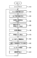
- FIG. 3 is a flowchart showing basic control processing by the air conditioner ECU 7.
- step 120 a switch signal is read from each switch such as a temperature setting switch.
- step 130 sensor signals from the inside air temperature sensor 71, outside air temperature sensor 72, solar radiation sensor 73, EVA surface temperature sensor 74, cooling water temperature sensor 75, humidity sensor 76, and the like are read.
- a target blowing temperature TAO of air blown into the vehicle interior is calculated based on the following formula 1 stored in advance in the ROM.
- TAO KSET ⁇ TSET-KR ⁇ TR-KAM ⁇ TAM-KS ⁇ TS + C
- TSET is the set temperature set by the temperature setting switch
- TR is the inside air temperature detected by the inside air temperature sensor 71
- TAM is the outside air temperature detected by the outside air temperature sensor 72
- TS is the solar radiation detected by the solar radiation sensor 73.
- KSET, KR, KAM, and KS are gains
- C is a correction constant.
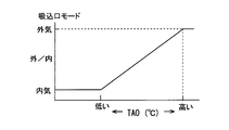
- step 150 for example, from the characteristic diagrams (maps) shown in FIGS. 5 and 6 stored in advance in the ROM, the inlet mode and the outlet corresponding to the target outlet temperature TAO are calculated. Determine the exit mode (blowing mode). In addition, when the suction inlet mode and the outlet mode are set by manual operation on the control panel P, the setting mode is determined.
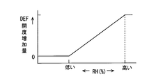
- step 150 when the blowing mode is determined as described above, for example, the defroster corresponding to the relative humidity RH of the inside air detected by the humidity sensor 76 from the characteristic diagram (map) shown in FIG.
- the opening degree of the opening 18 is increased.
- the defroster opening 18 is opened so that the increase amount of the defroster opening increases as the relative humidity RH increases. To do.
- the opening of the defroster opening 18 is increased so that the inner surface of the window glass 5 becomes cloudy.
- the closed defroster opening 18 is opened.
- the foot mode foot blowing mode
- the opening increase of the defroster opening 18 corresponding to the relative humidity RH of the inside air detected by the humidity sensor 76 has been described, but based on the dew point temperature of the inside air and the temperature of the inside surface of the window glass 5, the inner surface of the window glass 5. It is preferable to increase the opening degree of the defroster opening 18 in accordance with the degree of the ease of occurrence of dew condensation.
- the clouding phenomenon (fogging occurrence) on the inner surface of the window glass 5 is caused by the glass surface temperature (glass inner surface temperature) Tw and the dew point temperature Td of the air in contact therewith. That is, when the relationship of Tw ⁇ Td is established, condensation occurs on the inner surface of the window glass 5 and fogging occurs.
- the glass surface temperature Tw can be calculated from TAM, TR, TS, ⁇ am, ⁇ r, v, ⁇ , and ⁇ .
- the dew point temperature Td can be calculated from RH and TR.
- ⁇ am is the thermal conductivity outside the vehicle
- ⁇ r is the thermal conductivity inside the vehicle
- v is the vehicle speed
- ⁇ is the thickness of the windshield
- ⁇ is the thermal conductivity of the glass.
- the inner surface temperature of the window glass 5 may be accurately detected by a thermistor (an inner surface temperature detecting unit) provided so as to be in contact with the inner surface of the window glass 5.
- Step 150 corresponds to a blowing mode setting unit that sets a blowing mode of air into the vehicle compartment from the opening other than the defroster opening 18 and the defroster opening 18.
- step 160 correction control for preventing fogging of the outer surface of the window glass 5 is performed.
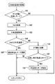
- FIG. 4 is a flowchart for explaining the general control operation of step 160.
- the air conditioner ECU 7 first determines whether or not the blowing mode in which the defroster opening 18 is opened is set (step 161). That is, in step 150, it is determined whether the foot blowing mode is set, or whether the mode in which the defroster opening 18 is opened for anti-fogging inside is set in the face blowing mode and the bi-level blowing mode. .
- step 161 When it is determined in step 161 that the defroster opening 18 is not in the blowing mode, the process proceeds to step 170.
- step 161 the auto mode (blow-out port automatic control mode) is set, and the blow mode determined corresponding to the target blow temperature TAO, and for the anti-fogging of the inner surface of the window glass 5 from the blow mode.
- the blowing mode set so that the defroster opening 18 opens it is determined whether or not the blowing mode in which the defroster opening 18 opens is set. That is, when the blowout port mode is set by manual operation on the control panel P, the process proceeds to step 170 without substantially performing the correction control for the outer antifogging.
- step 161 if it is determined in step 161 that the defroster opening 18 is in the blowing mode, the TAO calculated in step 140 is acquired (step 162). In addition, the outside air temperature TAM detected by the outside air temperature sensor 72 is acquired (step 163).
- step 162 corresponds to the temperature of the air blown from the defroster outlet to the vehicle interior when the defroster opening 18 is open. Therefore, step 162 is equivalent to the 1st temperature acquisition part which acquires the temperature of the air which blows off from a defroster blower outlet in this embodiment as the 1st temperature.
- step 163 The outside air temperature TAM acquired in step 163 is slightly higher than the dew point temperature of the outside air on the outer surface of the window glass 5 (temperature approximated on the higher temperature side) (if the outside air relative humidity is 100%). , Equal to dew point temperature).
- the outside air temperature TAM is acquired as the related temperature of the dew point temperature higher than the dew point temperature of the outside air on the outer surface of the window glass 5. Therefore, step 163 corresponds to a second temperature acquisition unit that acquires a related temperature of the dew point temperature higher than the dew point temperature of the outside air on the outer surface of the window glass 5 as the second temperature.
- Step 164 it is next determined whether or not the target outlet temperature TAO acquired in Step 162 is equal to or higher than the outside air temperature TAM (Step 164).
- step 164 when it is determined that the target blowing temperature TAO is equal to or higher than the outside air temperature TAM, the outer surface of the window glass 5 is not clouded by the wind blown from the defroster outlet toward the window glass 5.
- the blowing mode set in 150 is selected (step 165), and the process proceeds to step 170.
- step 164 when it is determined that the target blowing temperature TAO is lower than the outside air temperature TAM, the possibility that the outer surface of the window glass 5 is clouded by the wind blown from the defroster outlet toward the window glass 5 is high.
- a mode in which the defroster opening 18 is closed by the outlet switching damper 21 is set for the outlet mode set in step 150 (step 166).
- step 164 When the determination step of step 164 is executed, as shown in FIG. 8, the determination criterion is switched in consideration of the opening / closing state of the defroster opening 18 at the time of the previous control flow execution (so-called hysteresis is provided), It is preferable to prevent the hunting operation of the outlet switching damper 21.
- step 166 it is next determined whether or not the suction port mode set in step 150 is the inside air introduction mode for introducing only the inside air or the inside / outside air introduction mode for introducing both the inside air and the outside air (step 167). .
- step 167 If it is determined in step 167 that the suction port mode is not the inside air introduction mode or the inside / outside air introduction mode, that is, if it is determined that the suction port mode is the outside air introduction mode in which only the outside air is introduced, the process proceeds to step 170 as it is. On the other hand, if it is determined in step 167 that the suction port mode is not the inside air introduction mode or the inside / outside air introduction mode, the setting is changed to the outside air introduction mode (step 168), and the process proceeds to step 170.
- step 170 the blower air volume (substantially the voltage applied to the blower motor 32 of the blower 30) is determined.
- the air conditioner ECU 7 determines the blower air volume corresponding to the target blowing temperature TAO from the characteristic diagram (map) shown in FIG. 9 stored in advance in the ROM.
- the target damper opening SW of the air mix damper 52 is calculated based on the following mathematical formula 2 stored in advance in the ROM.
- SW [(TAO-TE) / (TW-TE)] ⁇ 100 (%)
- TE is an evaporation surface temperature detected by the evaporation surface temperature sensor 74
- TW is a cooling water temperature detected by the cooling water temperature sensor 75.
- the air mix damper 52 is controlled to a position (MAXCOOL position) that bypasses all of the cold air from the evaporator 45 from the heater core 51. Further, when calculated as SW ⁇ 100 (%), the air mix damper 52 is controlled to a position (MAXHOT position) through which all the cold air from the evaporator 45 passes through the heater core 51. Further, when calculated as 0 (%) ⁇ SW ⁇ 100 (%), the air mix damper 52 is an intermediate that passes a part of the cool air from the evaporator 45 through the heater core 51 and bypasses the rest of the cool air from the heater core 51. Controlled by position.
- a target evaporation surface temperature TEO for driving and controlling the compressor 41 is calculated.
- the air conditioner ECU 7 obtains the outer surface temperature of the heat exchange section of the evaporator 45 that is required when performing various controls such as temperature adjustment control in the vehicle interior, comfortable humidity control in the vehicle interior, and antifogging control on the inner surface of the window glass.
- the target EVA surface temperature TEO is calculated.
- the temperature adjustment control is control for driving the compressor 41 so as to obtain a target evaporation surface temperature corresponding to the target blowing temperature TAO.
- the comfortable humidity control is to drive and control the compressor 41 so as to achieve a target evaporation surface temperature corresponding to the vehicle interior humidity.
- the compressor humidity control is performed so that the vehicle interior humidity is between an upper limit set value and a lower limit set value.
- 41 is a control for driving 41.
- the anti-fogging control is a control for driving the compressor 41 so that the vehicle interior humidity does not reach the cloudy limit indoor humidity with respect to the outside air temperature so as to obtain a target evaporation surface temperature.
- the air conditioner ECU 7 proceeds to step 200 after setting the target evaporation surface temperature TEO, and determines the control state of the compressor 41 so that the detected temperature TE of the evaporation surface temperature sensor 74 becomes the set target evaporation surface temperature TEO.
- step 210 a control signal is output so that each control state calculated or determined in each of the above steps 150, 160, 170, 180, 200 is obtained. Then, the process returns to step 120.
- the air conditioner ECU 7 opens the defroster opening 18 in step 150 shown in FIG. 3 and blows wind from the defroster outlet toward the inner surface of the window glass 5 of the vehicle. Even if the blowing mode is set, if it is determined in step 164 shown in FIG. 4 that the target blowing temperature TAO is lower than the outside air temperature TAM, the blowing outlet switching damper is closed so as to close the defroster opening 18 in step 166. 21 is controlled.
- the defroster outlet opens the window glass 5.
- TAO the temperature of the air blown out from the defroster outlet
- TAM the outside air temperature of the outside air on the outer surface of the window glass 5
- the blowing mode for blowing wind from the defroster outlet toward the window glass 5 is set, the blowing of wind toward the inner surface of the window glass 5 by closing the defroster opening 18 is performed. It is prohibited and the occurrence of fogging on the outer surface of the window glass 5 can be suppressed.
- the outside air temperature TAM is acquired as the related temperature of the dew point temperature higher than the dew point temperature of the outside air on the outer surface of the window glass 5.
- the outside air temperature TAM is a temperature corresponding to the dew point temperature when the relative humidity of the outside air is 100%, and is usually slightly higher than the dew point temperature of the outside air (when the relative humidity is less than 100%). Therefore, the related temperature of the dew point temperature slightly higher than the dew point temperature of the outside air on the outer surface of the window glass 5, which is necessary for determining whether or not to close the defroster opening 18 in order to prevent the outer surface of the window glass 5 from being fogged. It can be easily obtained without detecting the humidity of the outside air.
- step 166 shown in FIG. 4 is executed and correction is performed so as to close the defroster opening 18 even when the blowing mode for opening the defroster opening 18 is set
- step 167, By 168, the mode of the suction port is set to the outside air introduction mode.
- the defroster opening 18 when the defroster opening 18 is closed to prevent the windshield from blowing toward the inner surface of the window glass 5 in order to prevent fogging of the outer surface of the window glass 5, the outside air whose absolute humidity is often lower than the inside air. It can be actively introduced into the air conditioning duct 20. Therefore, even if the defroster opening 18 is closed and the blowing of the wind toward the inner surface of the window glass 5 is prohibited, the opening to the vehicle interior is opened through the opening in the other opening other than the defroster opening 18. It is possible to blow off the conditioned air having a relatively low humidity and suppress fogging of the inner surface of the window glass 5.
- the first temperature acquired in step 162 is set as the target blowing temperature TAO, but is not limited to this.
- a thermistor or the like may be provided as a blowing temperature detection unit at the defroster outlet, and the temperature of the air blown out from the defroster outlet may be detected and acquired.
- the second temperature acquired in step 163 is the outside air temperature TAM.
- the second temperature may be any temperature related to the dew point temperature of the outside air on the outer surface of the window glass 5 or a dew point temperature higher than the dew point temperature.
- a humidity sensor 77 is provided as an outside air humidity detection unit for detecting the outside air relative humidity RHam, and the outside air temperature TAM detected by the outside air temperature sensor 72 and the outside air relative humidity RHam detected by the humidity sensor 77 are provided.
- the dew point temperature of the outside air may be calculated and acquired as the second temperature.
- the temperature of the outer surface of the window glass 5 is accurately detected by a thermistor (outer surface temperature detector) provided so as to be in contact with the outer surface of the window glass 5, and A highly accurate outside air dew point temperature may be acquired.
- the second temperature acquired in step 163 may be the outer surface temperature of the window glass 5.
- a temperature lower than the dew point temperature that fluctuates with a change in the dew point temperature of the outside air is detected, and a correction such as adding a predetermined temperature is added to the detected temperature to calculate a second temperature equal to or higher than the dew point temperature. , May be acquired.
- the setting change to the outside air introduction mode is performed in step 168.
- the present invention is not limited to this.
- the degree of the likelihood of dew condensation on the inner surface of the window glass 5 is also determined.
- the setting may be changed to the introduction mode.
- the suction inlet mode was set to the external air introduction mode by step 167,168,
- the suction inlet mode may be increased.
- the blower motor 32 which is an air volume adjustment part so that the air volume of the air which blows off into a vehicle interior may be increased.
- you may control the blower motor 32 which is an air volume adjustment part so that the air volume of the air which blows off into a vehicle interior may be increased.
- the blower motor 32 which is an air volume adjustment part so that the air volume of the air which blows off into a vehicle interior may be increased.
- the compressor 41 which is a cooling capacity adjusting unit is controlled so as to increase the cooling capacity of the air by the evaporator 45, and other openings other than the defroster opening 18 as the cooling capacity of the evaporator 45 increases.
- the air mix damper 52 which is a temperature adjusting unit, may be controlled so that the temperature at which the air is blown into the vehicle compartment does not change before and after the increase in the cooling capacity of the evaporator 45. Controlling the compressor 41 so as to increase the cooling capacity of the air by the evaporator 45 is to turn it on when the compressor 41 is off, and to increase the refrigerant discharge amount when the compressor 41 is on. It is to let you.
- the compressor 41 is controlled to increase the air cooling capacity by the evaporator 45.
- the air mix damper 52 is controlled so as not to change the temperature at which the air is blown into the passenger compartment. Therefore, the air is dehumidified by increasing the cooling capacity of the evaporator 45, and the temperature of the air cooled for dehumidification is adjusted by the air mix damper 52, so that the dehumidified air is released from the other openings in the open state. Blow out into the passenger compartment.
- the defroster opening 18 is closed, fogging of the inner surface of the window glass 5 can be suppressed.
- the correction control for the outer defrosting shown in FIG. 4 is performed, and the air outlet mode is set by manual operation.
- the air outlet mode is set by manual operation, the correction control for the outer anti-fogging is performed. It may be a thing.
- the window glass 5 was a vehicle front (front) window glass, it is not limited to this.
- the invention of the present disclosure may be applied to anti-fogging of side and rear window glasses.
Landscapes
- Engineering & Computer Science (AREA)
- Mechanical Engineering (AREA)
- Physics & Mathematics (AREA)
- Thermal Sciences (AREA)
- Air-Conditioning For Vehicles (AREA)
Abstract
Description
図1は、本開示の第1の実施形態における車両用空調装置の全体概略構成を示す模式図である。また、図2は車両用空調装置の制御系を示したブロック図である。
(数式1)
TAO=KSET×TSET-KR×TR-KAM×TAM-KS×TS+C
なお、TSETは温度設定スイッチにて設定した設定温度、TRは内気温センサ71にて検出した内気温度、TAMは外気温センサ72にて検出した外気温度、TSは日射センサ73にて検出した日射量である。また、KSET、KR、KAMおよびKSはゲインで、Cは補正用の定数である。
また、窓ガラス5の内表面温度は、窓ガラス5の内表面に接するように設けられたサーミスタ(内表面温度検出部)により精度よく検出するものであってもよい。
(数式2)
SW=[(TAO-TE)/(TW-TE)]×100(%)
なお、TEはエバ表面温度センサ74にて検出したエバ表面温度で、TWは冷却水温度センサ75にて検出した冷却水温度である。
以上、本開示は上述した実施形態を例として説明したが、上述した実施形態に何ら制限されることなく、本開示の主旨を逸脱しない範囲において種々変形して実施することが可能である。
Claims (5)
- 車室内へ吹き出す空気の通路が内部に形成された空調ダクト(10)と、
前記空調ダクト(10)に設けられ、車両の窓ガラス(5)の内面に向けて前記空気を吹き出すデフロスタ吹出口に接続されるデフロスタ開口部(18)と、
前記空調ダクト(10)に設けられ、前記車室内へ前記空気を吹き出す前記デフロスタ吹出口以外の吹出口に接続される、前記デフロスタ開口部(18)以外の他の開口部(19、20)と、
前記デフロスタ開口部(18)を開閉するドア部(21)と、
前記デフロスタ開口部(18)および前記他の開口部(19、20)から前記車室内への前記空気の吹出しモードを設定する吹出しモード設定部(150)と、
前記デフロスタ吹出口から吹き出される前記空気の温度(TAO)を第1温度として取得する第1温度取得部(162)と、
前記窓ガラス(5)の外面における外気の露点温度もしくは前記露点温度よりも高い前記露点温度の関連温度(TAM)を第2温度として取得する第2温度取得部(163)と、
前記吹出しモード設定部(150)により設定された前記吹出しモード、前記第1温度取得部(162)が取得した前記第1温度(TAO)および前記第2温度取得部(163)が取得した前記第2温度(TAM)に基づいて、前記ドア部(21)の開閉動作を制御する制御部(7)と、を備え、
前記制御部(7)は、前記吹出しモード設定部(150)により前記ドア部(21)が前記デフロスタ開口部(18)を開く吹出モードが設定されているときであっても、前記第1温度(TAO)が前記第2温度(TAM)よりも低い場合には、前記デフロスタ開口部(18)を閉じるように前記ドア部(21)を制御する車両用空調装置。 - 前記第2温度取得部(163)は、前記露点温度の関連温度である外気温度(TAM)を、第2温度として取得する請求項1に記載の車両用空調装置。
- 前記空調ダクト(10)内へ導入する内気及び外気の比率を調節する内外気比率調節部(13)を備え、
前記制御部(7)は、
前記吹出しモード設定部(150)により前記ドア部(21)が前記デフロスタ開口部(18)を開く吹出モードが設定されているときに、前記第1温度(TAO)および前記第2温度(TAM)に基づいて前記デフロスタ開口部(18)を閉じるように前記ドア部(21)を制御した場合には、
前記空調ダクト(10)内へ導入する外気比率を増大させるように前記内外気比率調節部(13)を制御し、
前記他の開口部(19、20)のうち開状態である開口部から前記車室内へ前記空気を吹き出すようにする請求項1または請求項2に記載の車両用空調装置。 - 前記車室内へ吹き出す前記空気の風量を調節する風量調節部(32)を備え、
前記制御部(7)は、
前記吹出しモード設定部(150)により前記ドア部(21)が前記デフロスタ開口部(18)を開く吹出モードが設定されているときに、前記第1温度(TAO)および前記第2温度(TAM)に基づいて前記デフロスタ開口部(18)を閉じるように前記ドア部(21)を制御した場合には、
前記車室内へ吹き出す前記空気の風量を増大させるように前記風量調節部(32)を制御し、
前記他の開口部(19、20)のうち開状態である開口部から前記車室内へ前記空気を吹き出すようにする請求項1ないし請求項3のいずれか1つに記載の車両用空調装置。 - 前記空調ダクト(10)内を流通する前記空気を冷却する冷却用熱交換器(45)と、
前記冷却用熱交換器(45)による前記空気の冷却能力を調節する冷却能力調節部(41)と、
前記冷却用熱交換器(45)で冷却された前記空気の温度調節をする温度調節部(52)と、を備え、
前記制御部(7)は、
前記吹出しモード設定部(150)により前記ドア部(21)が前記デフロスタ開口部(18)を開く吹出モードが設定されているときに、前記第1温度(TAO)および前記第2温度(TAM)に基づいて前記デフロスタ開口部(18)を閉じるように前記ドア部(21)を制御した場合には、
前記冷却用熱交換器(45)による前記空気の冷却能力を増大するように前記冷却能力調節部(41)を制御するとともに、前記他の開口部(19、20)から前記車室内への吹出し温度が前記冷却能力の増大前後で変化しないように前記温度調節部(52)を制御し、
前記他の開口部(19、20)のうち開状態である開口部から前記車室内へ前記空気を吹き出すようにする請求項1ないし請求項4のいずれか1つに記載の車両用空調装置。
Priority Applications (3)
| Application Number | Priority Date | Filing Date | Title |
|---|---|---|---|
| US14/122,189 US9475463B2 (en) | 2011-05-30 | 2012-04-17 | Air-conditioner for vehicle |
| CN201280026750.5A CN103561975B (zh) | 2011-05-30 | 2012-04-17 | 车用空气调节器 |
| DE112012002302.1T DE112012002302T5 (de) | 2011-05-30 | 2012-04-17 | Klimaanlage für Fahrzeug |
Applications Claiming Priority (2)
| Application Number | Priority Date | Filing Date | Title |
|---|---|---|---|
| JP2011120505A JP5445514B2 (ja) | 2011-05-30 | 2011-05-30 | 車両用空調装置 |
| JP2011-120505 | 2011-05-30 |
Publications (1)
| Publication Number | Publication Date |
|---|---|
| WO2012164812A1 true WO2012164812A1 (ja) | 2012-12-06 |
Family
ID=47258690
Family Applications (1)
| Application Number | Title | Priority Date | Filing Date |
|---|---|---|---|
| PCT/JP2012/002634 Ceased WO2012164812A1 (ja) | 2011-05-30 | 2012-04-17 | 車両用空調装置 |
Country Status (5)
| Country | Link |
|---|---|
| US (1) | US9475463B2 (ja) |
| JP (1) | JP5445514B2 (ja) |
| CN (1) | CN103561975B (ja) |
| DE (1) | DE112012002302T5 (ja) |
| WO (1) | WO2012164812A1 (ja) |
Cited By (1)
| Publication number | Priority date | Publication date | Assignee | Title |
|---|---|---|---|---|
| WO2024241799A1 (ja) * | 2023-05-22 | 2024-11-28 | サンデン株式会社 | 車両用空調装置 |
Families Citing this family (15)
| Publication number | Priority date | Publication date | Assignee | Title |
|---|---|---|---|---|
| US20140004782A1 (en) * | 2012-06-29 | 2014-01-02 | Ford Global Technologies, Llc | System and method of controlling ventilation of a passenger compartment of a vehicle |
| EP2743473B1 (en) * | 2012-12-11 | 2016-07-13 | V2 Plug-in Hybrid Vehicle Partnership Handelsbolag | Running a PHEV in EV mode under cold conditions |
| KR20160031654A (ko) * | 2014-09-12 | 2016-03-23 | 현대자동차주식회사 | 차량의 디포깅 방법 및 시스템 |
| JP6468348B2 (ja) * | 2015-04-24 | 2019-02-13 | 株式会社デンソー | 車両用防曇装置 |
| US10787154B2 (en) * | 2016-09-07 | 2020-09-29 | Ford Global Technologies, Llc | Windshield defroster with secondary ducted outlet |
| JP6583195B2 (ja) * | 2016-09-07 | 2019-10-02 | 株式会社デンソー | 車両用空調装置 |
| KR102028884B1 (ko) * | 2017-08-11 | 2019-10-04 | 현대모비스 주식회사 | 차량용 공조장치 제어 방법 |
| KR102528113B1 (ko) * | 2018-06-01 | 2023-05-04 | 한온시스템 주식회사 | 차량의 공조장치 및 그 제어방법 |
| JP7077980B2 (ja) * | 2019-02-01 | 2022-05-31 | トヨタ自動車株式会社 | 車両用インストルメントパネル構造 |
| FR3097623A1 (fr) * | 2019-06-19 | 2020-12-25 | Valeo Systemes Thermiques | Procédé de contrôle d’un circuit de conditionnement thermique d’un flux d’air |
| CN112208299A (zh) * | 2020-10-30 | 2021-01-12 | 上海马勒热系统有限公司 | 电动汽车空调系统新回风装置及其控制方法 |
| US11724568B2 (en) | 2020-12-09 | 2023-08-15 | Ford Global Technologies, Llc | Temperature regulating system for vehicle interior surfaces |
| KR20220138743A (ko) * | 2021-04-06 | 2022-10-13 | 현대자동차주식회사 | 차량용 hvac시스템의 제어방법 |
| CN114274736B (zh) * | 2022-02-16 | 2023-11-21 | 一汽解放汽车有限公司 | 汽车空调防雾控制方法、装置、设备、存储介质 |
| CN116021955B (zh) * | 2023-01-17 | 2025-12-30 | 长城汽车股份有限公司 | 车辆循环风门控制方法、装置、设备、存储介质及车辆 |
Citations (4)
| Publication number | Priority date | Publication date | Assignee | Title |
|---|---|---|---|---|
| JPS61139514A (ja) * | 1984-12-13 | 1986-06-26 | Nissan Motor Co Ltd | 車両用空調装置 |
| JPH07172140A (ja) * | 1993-12-22 | 1995-07-11 | Nissan Motor Co Ltd | 車両用空調装置 |
| JP2000103323A (ja) * | 1998-09-29 | 2000-04-11 | Mazda Motor Corp | 車両用空気調和装置 |
| JP2010167895A (ja) * | 2009-01-22 | 2010-08-05 | Sanden Corp | 車両用空調装置 |
Family Cites Families (6)
| Publication number | Priority date | Publication date | Assignee | Title |
|---|---|---|---|---|
| JPS5663513A (en) | 1979-10-31 | 1981-05-30 | Diesel Kiki Co Ltd | Method and apparatus for preventing clouding inside car glass and control moisture for car-air conditioner |
| JPH051515U (ja) | 1991-06-26 | 1993-01-14 | 三菱自動車工業株式会社 | 車両用エアコンの制御装置 |
| DE19728579C1 (de) * | 1997-07-04 | 1998-06-10 | Daimler Benz Ag | Fahrzeugklimaanlage mit außentaupunktabhängiger Klimatisierungsfunktion |
| US6508408B2 (en) * | 2001-05-08 | 2003-01-21 | Delphi Technologies, Inc. | Automatic windglass fog prevention method for a vehicle climate control system |
| JP2007008449A (ja) | 2005-05-31 | 2007-01-18 | Denso Corp | 車両用空調装置 |
| JP4424409B2 (ja) * | 2007-11-02 | 2010-03-03 | 株式会社デンソー | 車両用空調装置 |
-
2011
- 2011-05-30 JP JP2011120505A patent/JP5445514B2/ja not_active Expired - Fee Related
-
2012
- 2012-04-17 CN CN201280026750.5A patent/CN103561975B/zh not_active Expired - Fee Related
- 2012-04-17 DE DE112012002302.1T patent/DE112012002302T5/de not_active Withdrawn
- 2012-04-17 WO PCT/JP2012/002634 patent/WO2012164812A1/ja not_active Ceased
- 2012-04-17 US US14/122,189 patent/US9475463B2/en not_active Expired - Fee Related
Patent Citations (4)
| Publication number | Priority date | Publication date | Assignee | Title |
|---|---|---|---|---|
| JPS61139514A (ja) * | 1984-12-13 | 1986-06-26 | Nissan Motor Co Ltd | 車両用空調装置 |
| JPH07172140A (ja) * | 1993-12-22 | 1995-07-11 | Nissan Motor Co Ltd | 車両用空調装置 |
| JP2000103323A (ja) * | 1998-09-29 | 2000-04-11 | Mazda Motor Corp | 車両用空気調和装置 |
| JP2010167895A (ja) * | 2009-01-22 | 2010-08-05 | Sanden Corp | 車両用空調装置 |
Cited By (1)
| Publication number | Priority date | Publication date | Assignee | Title |
|---|---|---|---|---|
| WO2024241799A1 (ja) * | 2023-05-22 | 2024-11-28 | サンデン株式会社 | 車両用空調装置 |
Also Published As
| Publication number | Publication date |
|---|---|
| US20140087644A1 (en) | 2014-03-27 |
| CN103561975A (zh) | 2014-02-05 |
| DE112012002302T5 (de) | 2014-03-06 |
| CN103561975B (zh) | 2016-03-16 |
| JP2012245921A (ja) | 2012-12-13 |
| JP5445514B2 (ja) | 2014-03-19 |
| US9475463B2 (en) | 2016-10-25 |
Similar Documents
| Publication | Publication Date | Title |
|---|---|---|
| JP5445514B2 (ja) | 車両用空調装置 | |
| JP3841039B2 (ja) | 車両用空調装置 | |
| JP4314933B2 (ja) | 車両用空調装置 | |
| JP5316264B2 (ja) | 車両用空調装置 | |
| JP6583195B2 (ja) | 車両用空調装置 | |
| JP2010030435A (ja) | 車両用空調装置 | |
| JP2001113939A (ja) | 車両用空調装置 | |
| JP4858353B2 (ja) | 車両用空調装置 | |
| JP4407368B2 (ja) | 車両用空調装置 | |
| JP2002036847A (ja) | 車両用空調装置 | |
| JP4561014B2 (ja) | 車両用空調装置 | |
| JP5245537B2 (ja) | 車両用空調装置 | |
| JP3862942B2 (ja) | 車両用空調装置 | |
| JP2002002267A (ja) | 車両用空調装置 | |
| JP3201125B2 (ja) | 車両用空調装置 | |
| JP2002283839A (ja) | 車両用冷房装置 | |
| JP2002331820A (ja) | 車両用空調装置 | |
| JP2008179202A (ja) | 空調装置 | |
| JPH11151930A (ja) | 車両用空調装置 | |
| JP3326954B2 (ja) | 車両用空調装置 | |
| JP2006224705A (ja) | 車両用空調装置 | |
| JP4306102B2 (ja) | 車両用空調装置 | |
| JP4613942B2 (ja) | 車両用空調装置 | |
| JP2005349939A (ja) | 車両用空調装置 | |
| JP4218550B2 (ja) | 車両用空調装置 |
Legal Events
| Date | Code | Title | Description |
|---|---|---|---|
| WWE | Wipo information: entry into national phase |
Ref document number: 201280026750.5 Country of ref document: CN |
|
| 121 | Ep: the epo has been informed by wipo that ep was designated in this application |
Ref document number: 12794090 Country of ref document: EP Kind code of ref document: A1 |
|
| WWE | Wipo information: entry into national phase |
Ref document number: 14122189 Country of ref document: US |
|
| WWE | Wipo information: entry into national phase |
Ref document number: 1120120023021 Country of ref document: DE Ref document number: 112012002302 Country of ref document: DE |
|
| 122 | Ep: pct application non-entry in european phase |
Ref document number: 12794090 Country of ref document: EP Kind code of ref document: A1 |