WO2012161136A1 - 電動機付き車両の駆動装置 - Google Patents
電動機付き車両の駆動装置 Download PDFInfo
- Publication number
- WO2012161136A1 WO2012161136A1 PCT/JP2012/062859 JP2012062859W WO2012161136A1 WO 2012161136 A1 WO2012161136 A1 WO 2012161136A1 JP 2012062859 W JP2012062859 W JP 2012062859W WO 2012161136 A1 WO2012161136 A1 WO 2012161136A1
- Authority
- WO
- WIPO (PCT)
- Prior art keywords
- drive
- motor
- drive device
- outer cup
- vehicle
- Prior art date
Links
Images


Classifications
-
- F—MECHANICAL ENGINEERING; LIGHTING; HEATING; WEAPONS; BLASTING
- F16—ENGINEERING ELEMENTS AND UNITS; GENERAL MEASURES FOR PRODUCING AND MAINTAINING EFFECTIVE FUNCTIONING OF MACHINES OR INSTALLATIONS; THERMAL INSULATION IN GENERAL
- F16C—SHAFTS; FLEXIBLE SHAFTS; ELEMENTS OR CRANKSHAFT MECHANISMS; ROTARY BODIES OTHER THAN GEARING ELEMENTS; BEARINGS
- F16C1/00—Flexible shafts; Mechanical means for transmitting movement in a flexible sheathing
- F16C1/02—Flexible shafts; Mechanical means for transmitting movement in a flexible sheathing for conveying rotary movements
-
- H—ELECTRICITY
- H02—GENERATION; CONVERSION OR DISTRIBUTION OF ELECTRIC POWER
- H02K—DYNAMO-ELECTRIC MACHINES
- H02K7/00—Arrangements for handling mechanical energy structurally associated with dynamo-electric machines, e.g. structural association with mechanical driving motors or auxiliary dynamo-electric machines
- H02K7/10—Structural association with clutches, brakes, gears, pulleys or mechanical starters
- H02K7/116—Structural association with clutches, brakes, gears, pulleys or mechanical starters with gears
-
- F—MECHANICAL ENGINEERING; LIGHTING; HEATING; WEAPONS; BLASTING
- F16—ENGINEERING ELEMENTS AND UNITS; GENERAL MEASURES FOR PRODUCING AND MAINTAINING EFFECTIVE FUNCTIONING OF MACHINES OR INSTALLATIONS; THERMAL INSULATION IN GENERAL
- F16D—COUPLINGS FOR TRANSMITTING ROTATION; CLUTCHES; BRAKES
- F16D3/00—Yielding couplings, i.e. with means permitting movement between the connected parts during the drive
- F16D3/16—Universal joints in which flexibility is produced by means of pivots or sliding or rolling connecting parts
- F16D3/20—Universal joints in which flexibility is produced by means of pivots or sliding or rolling connecting parts one coupling part entering a sleeve of the other coupling part and connected thereto by sliding or rolling members
- F16D3/202—Universal joints in which flexibility is produced by means of pivots or sliding or rolling connecting parts one coupling part entering a sleeve of the other coupling part and connected thereto by sliding or rolling members one coupling part having radially projecting pins, e.g. tripod joints
- F16D3/205—Universal joints in which flexibility is produced by means of pivots or sliding or rolling connecting parts one coupling part entering a sleeve of the other coupling part and connected thereto by sliding or rolling members one coupling part having radially projecting pins, e.g. tripod joints the pins extending radially outwardly from the coupling part
- F16D3/2055—Universal joints in which flexibility is produced by means of pivots or sliding or rolling connecting parts one coupling part entering a sleeve of the other coupling part and connected thereto by sliding or rolling members one coupling part having radially projecting pins, e.g. tripod joints the pins extending radially outwardly from the coupling part having three pins, i.e. true tripod joints
-
- H—ELECTRICITY
- H02—GENERATION; CONVERSION OR DISTRIBUTION OF ELECTRIC POWER
- H02K—DYNAMO-ELECTRIC MACHINES
- H02K7/00—Arrangements for handling mechanical energy structurally associated with dynamo-electric machines, e.g. structural association with mechanical driving motors or auxiliary dynamo-electric machines
- H02K7/006—Structural association of a motor or generator with the drive train of a motor vehicle
-
- H—ELECTRICITY
- H02—GENERATION; CONVERSION OR DISTRIBUTION OF ELECTRIC POWER
- H02K—DYNAMO-ELECTRIC MACHINES
- H02K7/00—Arrangements for handling mechanical energy structurally associated with dynamo-electric machines, e.g. structural association with mechanical driving motors or auxiliary dynamo-electric machines
- H02K7/08—Structural association with bearings
- H02K7/086—Structural association with bearings radially supporting the rotor around a fixed spindle; radially supporting the rotor directly
- H02K7/088—Structural association with bearings radially supporting the rotor around a fixed spindle; radially supporting the rotor directly radially supporting the rotor directly
-
- B—PERFORMING OPERATIONS; TRANSPORTING
- B60—VEHICLES IN GENERAL
- B60L—PROPULSION OF ELECTRICALLY-PROPELLED VEHICLES; SUPPLYING ELECTRIC POWER FOR AUXILIARY EQUIPMENT OF ELECTRICALLY-PROPELLED VEHICLES; ELECTRODYNAMIC BRAKE SYSTEMS FOR VEHICLES IN GENERAL; MAGNETIC SUSPENSION OR LEVITATION FOR VEHICLES; MONITORING OPERATING VARIABLES OF ELECTRICALLY-PROPELLED VEHICLES; ELECTRIC SAFETY DEVICES FOR ELECTRICALLY-PROPELLED VEHICLES
- B60L2220/00—Electrical machine types; Structures or applications thereof
- B60L2220/40—Electrical machine applications
- B60L2220/46—Wheel motors, i.e. motor connected to only one wheel
-
- B—PERFORMING OPERATIONS; TRANSPORTING
- B60—VEHICLES IN GENERAL
- B60L—PROPULSION OF ELECTRICALLY-PROPELLED VEHICLES; SUPPLYING ELECTRIC POWER FOR AUXILIARY EQUIPMENT OF ELECTRICALLY-PROPELLED VEHICLES; ELECTRODYNAMIC BRAKE SYSTEMS FOR VEHICLES IN GENERAL; MAGNETIC SUSPENSION OR LEVITATION FOR VEHICLES; MONITORING OPERATING VARIABLES OF ELECTRICALLY-PROPELLED VEHICLES; ELECTRIC SAFETY DEVICES FOR ELECTRICALLY-PROPELLED VEHICLES
- B60L2240/00—Control parameters of input or output; Target parameters
- B60L2240/40—Drive Train control parameters
- B60L2240/42—Drive Train control parameters related to electric machines
- B60L2240/421—Speed
-
- Y—GENERAL TAGGING OF NEW TECHNOLOGICAL DEVELOPMENTS; GENERAL TAGGING OF CROSS-SECTIONAL TECHNOLOGIES SPANNING OVER SEVERAL SECTIONS OF THE IPC; TECHNICAL SUBJECTS COVERED BY FORMER USPC CROSS-REFERENCE ART COLLECTIONS [XRACs] AND DIGESTS
- Y02—TECHNOLOGIES OR APPLICATIONS FOR MITIGATION OR ADAPTATION AGAINST CLIMATE CHANGE
- Y02T—CLIMATE CHANGE MITIGATION TECHNOLOGIES RELATED TO TRANSPORTATION
- Y02T10/00—Road transport of goods or passengers
- Y02T10/60—Other road transportation technologies with climate change mitigation effect
- Y02T10/64—Electric machine technologies in electromobility
Definitions
- the present invention relates to a drive device for a vehicle with an electric motor in which at least a drive motor is used as a drive source, and the drive motor and drive wheels are connected by a constant velocity joint.
- a drive motor may be used as a drive source.
- vehicles with electric motors such as a hybrid vehicle on which an engine and a drive motor are mounted and an electric vehicle (or a fuel cell electric vehicle) on which only the drive motor is mounted are known.
- This type of vehicle with an electric motor is generally configured to travel under the rotational action of the drive wheel by transmitting the rotational force of the drive motor to the drive wheel (tire) via a constant velocity joint. ing.
- a drive mechanism for an electric vehicle disclosed in Japanese Patent Laid-Open No. 4-325803 is known.
- a stator 3 around which a coil 2 is wound in a motor case 1 is press-fitted and fixed.
- a cup-shaped rotor 4 constituting an air-core motor is accommodated in the motor case 1, and the cup-shaped rotor 4 is rotatable by a permanent magnet 5.
- a motor side constant velocity joint 6 is fixed inside the bottom of the cup-shaped rotor 4, and a shaft 7 having one end connected to the motor side constant velocity joint 6 is connected to a tire 9 via a tire side constant velocity joint 8. Connected to the side.
- the drive shaft 7 can be drawn to the air core part of the cup-shaped rotor 4, and the length of the drive shaft 7 can be made more than twice that of the conventional drive mechanism. .
- an air-core motor is configured by disposing the cup-shaped rotor 4 in the motor case 1.
- an air core is provided in the motor, there is a problem that the entire motor is considerably enlarged in the radial direction.
- a general object of the present invention is to provide a drive device for a vehicle with an electric motor that does not require an air core.
- the main object of the present invention is to provide a drive device for a motor-equipped vehicle that can be reduced in size and weight.
- Another object of the present invention is to provide a drive device for a vehicle with an electric motor capable of maintaining the stroke amount of the drive shaft.
- Another object of the present invention is to provide a drive device for a vehicle with an electric motor that can improve the output torque satisfactorily.
- the present invention relates to a drive device for a vehicle with an electric motor in which at least a drive motor is used as a drive source, and the drive motor and drive wheels are connected by an inboard constant velocity joint, a drive shaft and an outboard constant velocity joint. Is.
- the inboard constant velocity joint is accommodated in the inner peripheral portion of the driving motor, and the outer cup constituting the inboard constant velocity joint has a joint portion in the inner peripheral portion.
- a sliding surface that slides is provided, and an outer peripheral portion is rotatably supported by an inner peripheral portion of the driving motor.
- the rotational force of the driving motor is directly transmitted to the outer cup by rotatably supporting the outer cup constituting the inboard constant velocity joint on the inner peripheral portion of the driving motor.
- the driving force can be reliably and easily transmitted to the inboard constant velocity joint. Therefore, it is possible to reduce the size and weight without providing an air core.
- the joint portion of the inboard constant velocity joint is accommodated in the inner peripheral portion of the drive motor, the stroke amount of the drive shaft can be maintained well.
- this drive device it is preferable that a reduction mechanism for decelerating the rotation of the drive motor and transmitting it to the inboard constant velocity joint is accommodated in the inner peripheral portion of the drive motor.
- the inboard constant velocity joint includes an outer cup in which a joint portion is accommodated, and the shaft portion protrudes axially outward from the bottom portion of the outer cup, and the drive The apparatus includes a speed reduction mechanism that is coupled to the shaft portion and is accommodated in the inner peripheral portion of the drive motor.
- the speed reduction mechanism includes a sun gear provided in a rotor constituting the drive motor, a planetary gear supported by a carrier member fixed to the shaft portion, and a stator side constituting the drive motor. It is preferable that the sun gear, the planetary gear, and the internal gear are accommodated in the inner peripheral portion of the rotor.
- FIG. 4 is a cross-sectional explanatory view taken along the line IV-IV in FIG. 3 of the speed reduction mechanism constituting the drive device. It is a schematic sectional explanatory drawing of the drive device of the vehicle with an electric motor which concerns on the 2nd modification of 1st Embodiment.
- FIG. 4 is a cross-sectional explanatory view taken along the line IV-IV in FIG. 3 of the speed reduction mechanism constituting the drive device.
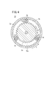
- FIG. 6 is a cross-sectional explanatory view taken along the line VI-VI in FIG. 5 of the speed reduction mechanism constituting the driving device. It is explanatory drawing of the vehicle by which the drive device of the vehicle with an electric motor which concerns on 2nd Embodiment of this invention is employ
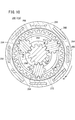
- FIG. 9 is a cross-sectional explanatory view taken along the line IX-IX in FIG. 8 of the speed reduction mechanism constituting the drive device. It is operation
- FIG. 4 is an explanatory diagram of a drive mechanism disclosed in Japanese Patent Laid-Open No. 4-325803.
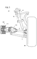
- a drive device 10 for a vehicle with an electric motor is mounted on a vehicle 11, and the vehicle 11 connects a drive wheel DW and a drive device 10 to a drive shaft 12. Connect through.
- the driving wheel DW is elastically supported with respect to the vehicle body by the suspension SP.
- the suspension SP includes a link mechanism L that connects the drive wheels DW to the vehicle body, and a shock absorber SA that absorbs vibration transmitted to the drive wheels DW.
- An inboard joint (inboard constant velocity joint) 16 connected to the drive motor 14 is provided on one end side of the drive shaft 12.
- the inboard joint 16 constitutes, for example, a tripart type constant velocity joint.
- An outboard joint (outboard constant velocity joint) 17 connected to the drive wheel DW is provided on the other end side of the drive shaft 12.
- a spline shaft portion 18 is provided at one end portion of the drive shaft 12, and a joint portion of the inboard joint 16, for example, a spider 20 is externally mounted on the spline shaft portion 18.
- a plurality of, for example, three trunnions 22, for example, are integrally formed on the outer peripheral portion of the spider 20 with a predetermined angular interval (equal angular interval).
- a ring-shaped roller member 26 is rotatably attached to the outer peripheral portion of each trunnion 22 via a rolling element (needle, roller, etc.) 24.
- the inboard joint 16 includes a bottomed cylindrical outer cup 28.
- the outer cup 28 is integrally provided with a shaft portion 30 on one end side (bottomed side), and the other end side is opened.
- a guide groove 34 in which the roller member 26 slides rotatably is formed in the inner peripheral portion 32 of the outer cup 28.
- three guide grooves 34 are provided in the inner peripheral portion 32 so as to be spaced apart at equal angular intervals, and each of the guide grooves 34 extends in the axial direction of the outer cup 28.
- Both ends of the boot 36 are fastened and fixed to the front end of the outer cup 28 and the drive shaft 12 via band members 38, 38.
- the driving motor 14 includes a motor case 40, and the motor case 40 is substantially divided into a first case part 40a and a second case part 40b.
- a plurality of coils 44 constituting the stator 42 are arranged around the second case portion 40b.
- Each coil 44 is connected to a drive circuit 46, and the stator 42 is provided with a hall element 48 for detecting a magnetic field.
- the drive motor 14 constitutes a brushless motor.
- magnetic field detection is performed via the Hall element 48.
- the rotor 50 is disposed inside the stator 42.
- the rotor 50 includes an outer cup 28 and a plurality of permanent magnets 52 that are directly fixed to the outer peripheral portion of the outer cup 28.
- the outer cup 28 is rotatably supported in the first case portion 40 a and the second case portion 40 b via a plurality of angular bearings 54.
- Each permanent magnet 52 is arranged around the outer cup 28 in an alternating manner with S and N poles alternately.
- the drive motor 14 has a brushless DC motor structure, and the drive circuit 46 controls the S pole and the N pole to perform switching operations. Therefore, the outer cup 28 is rotated under the action of the repulsive force and the attractive force generated between the permanent magnet 52 and the coil 44 in which the S pole and the N pole are alternately arranged on the outer peripheral portion of the outer cup 28.
- the outer cup 28 constituting the inboard joint 16 is rotatably supported on the inner peripheral portion of the motor case 40 constituting the drive motor 14 via a plurality of angular bearings 54. .
- the outer cup 28 forms a rotor 50 by disposing a plurality of permanent magnets 52 on the outer peripheral portion, and the rotational force of the driving motor 14 is directly transmitted to the outer cup 28. For this reason, it is possible to transmit the driving force (rotational force) to the inboard joint 16 reliably and easily, and there is no need to provide a conventional air core, which makes it possible to reduce the size and weight. can get.
- the spider 20 which is the joint portion of the inboard joint 16 is accommodated in the inner peripheral portion of the drive motor 14.
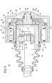
- FIG. 3 is a schematic cross-sectional explanatory view of a drive device 60 for a vehicle with an electric motor according to a first modification of the first embodiment.
- the driving device 60 includes a driving motor 62, and the driving motor 62 includes a stator 42 and a rotor 64.
- the rotor 64 has a shaft portion 66 that is rotatably supported at the center portion of the motor case 40 via an angular bearing 54, and a relatively large-diameter ring portion is provided at an inner side end portion of the shaft portion 66. 68 is provided integrally. On the outer periphery of the ring portion 68, a plurality of permanent magnets 52 are arranged around the S pole and N pole alternately.
- a reduction mechanism 72 is provided between the outer cup 70 and the rotor 64 constituting the inboard joint 16.
- the speed reduction mechanism 72 includes a sun gear 74 fixed to the rotation axis of the rotor 64 and a plurality of, for example, three planetary gears rotatably supported on the end surface 70 a of the outer cup 70. 76, and an internal gear 78 in which a tooth portion extending in a direction orthogonal to the end surface 70a of the outer cup 70 is formed on the inner peripheral portion.
- Each planetary gear 76 meshes with the sun gear 74 and the internal gear 78 integrally.
- the rotor 64 is rotated under the switching action of the drive circuit 46. For this reason, the sun gear 74 fixed coaxially to the rotor 64 rotates in the direction of the arrow a1 in FIG. 4, for example.
- Each planetary gear 76 meshes with the sun gear 74, and when the sun gear 74 rotates in the arrow a1 direction, a rotational force in the arrow b1 direction is applied to each planetary gear 76. At that time, each planetary gear 76 meshes with the internal gear 78.
- each planetary gear 76 is rotatably supported by the end surface 70a of the outer cup 70, while the internal gear 78 is formed directly on the outer cup 70. Accordingly, the outer cup 70 rotates in the direction of the arrow c in FIG. 4, and the deceleration state is set by the gear ratio of the sun gear 74, the planetary gear 76 and the internal gear 78.
- the transmission force of the rotational force from the driving motor 62 to the inboard joint 16 can be improved, and the necessary torque, rotational speed, and the like can be set. The effect that there is.
- FIG. 5 is a schematic cross-sectional explanatory diagram of a drive device 90 for a vehicle with an electric motor according to a second modification.
- the driving device 90 includes a driving motor 92, and the driving motor 92 includes a stator 42 and a rotor 94.
- the rotor 94 has a shaft portion 96 that is rotatably supported by the shaft center of the motor case 40, similarly to the rotor 64 of the first modification, and a ring portion 68 and an inner side of the shaft portion 96.
- the bulging part 98 is provided integrally.
- the driving device 90 includes a speed reduction mechanism 100.
- the speed reduction mechanism 100 includes a plurality of, for example, a sun gear 102 formed on the outer peripheral portion of the bulging portion 98 of the rotor 94 and an outer cup 104 constituting the inboard joint 16. It has three planetary gears 106 and an internal gear 108 formed on the motor case 40 side.
- the planetary gears 106 are rotatably mounted on the carrier member 110 fixed to the tip of the outer cup 104 and are spaced apart from each other at equal angular intervals.
- the internal gear 108 is formed at the tip of the inner peripheral portion of the cylindrical portion 112 extending from the inner peripheral end portion of the second case portion 40b into the first case portion 40a.
- the rotor 94 rotates in the direction of the arrow a2 in FIG. 6, for example, by switching control of the drive circuit 46. For this reason, the sun gear 102 provided in the bulging part 98 of the rotor 94 rotates in the arrow a2 direction, and each planetary gear 106 that meshes with the sun gear 102 rotates in the arrow b2 direction.
- Each planetary gear 106 meshes with an internal gear 108 formed in the cylindrical portion 112 on the motor case 40 side. Therefore, when the planetary gear 106 rotates in the arrow b2 direction, the outer cup 104 rotates in the arrow d direction (the direction opposite to the arrow c direction) via the carrier member 110.
- a drive device 210 for a vehicle with an electric motor is mounted on a vehicle 11, and the vehicle 11 connects a drive wheel DW and the drive device 210 to a drive shaft. 12 is connected.
- the driving wheel DW is elastically supported with respect to the vehicle body by the suspension SP.
- the suspension SP includes a link mechanism L that connects the drive wheels DW to the vehicle body, and a shock absorber SA that absorbs vibration transmitted to the drive wheels DW.
- An inboard joint (inboard constant velocity joint) 216 connected to the driving motor 214 is provided on one end side of the drive shaft 12.
- the inboard joint 216 constitutes, for example, a tripart type constant velocity joint.
- An outboard joint (outboard constant velocity joint) 17 connected to the drive wheel DW is provided on the other end side of the drive shaft 12.
- a spline shaft portion 18 is provided at one end portion of the drive shaft 12, and a joint portion of the inboard joint 216, for example, a spider 20 is externally mounted on the spline shaft portion 18.
- a plurality of, for example, three trunnions 22, for example, are integrally formed on the outer peripheral portion of the spider 20 with a predetermined angular interval (equal angular interval).
- the inboard joint 216 various constant velocity joints conventionally used can be adopted.
- a ring-shaped roller member 26 is rotatably attached to the outer peripheral portion of each trunnion 22 via a rolling element (needle, roller, etc.) 24.
- the inboard joint 216 includes a bottomed cylindrical outer cup 228.
- the outer cup 228 has a shaft portion 230 integrally protruding outward from the bottom portion (one end side) in the axial direction, and the other end side is opened.
- a guide groove 34 in which the roller member 26 slides rotatably is formed in the inner peripheral portion 232 of the outer cup 228, a guide groove 34 in which the roller member 26 slides rotatably is formed.
- three guide grooves 34 are provided in the inner peripheral portion 232 so as to be spaced apart at equal angular intervals, and are each formed to extend in the axial direction of the outer cup 228.
- the both ends of the boot 36 are fastened and fixed to the front end of the outer cup 228 and the drive shaft 12 via band members 38, 38.
- the driving device 210 includes a speed reduction mechanism 240 that is connected to the shaft portion 230 of the outer cup 228 and is accommodated in the inner peripheral portion of the driving motor 214.
- the drive motor 214 is provided with a motor case 242, and the motor case 242 has a bottomed cylindrical shape.
- a disc-shaped bottom 242 a is provided on one end side of the motor case 242.
- a plurality of coils 246 constituting the stator 244 are arranged around the inner peripheral portion of the motor case 242.
- Each coil 246 is connected to a drive circuit (not shown).
- a brushless DC motor structure is employed for the drive motor 214.
- a rotor 248 is disposed on the inner periphery of the stator 244. As shown in FIG. 8, the rotor 248 has a shaft portion 252 that is rotatably supported via a bearing 250 at the center portion of the bottom portion 242 a of the motor case 242.
- the shaft portion 252 is integrally provided with a ring portion 256 having a relatively large diameter via a disc portion 254, and a bulging portion 258 is integrally provided coaxially inside the shaft portion 252. .
- a plurality of permanent magnets 260 are arranged around the S poles and N poles alternately.
- the rotor structure may be constituted by a laminated body of electromagnetic steel plates instead of the permanent magnet 260.
- the speed reduction mechanism 240 includes a sun gear 262 formed on the outer peripheral portion of the bulging portion 258 of the rotor 248, a plurality of, for example, three planetary gears 264 supported by the outer cup 228 constituting the inboard joint 216, and a motor case. And an internal gear 266 formed on the 242 side.
- the sun gear 262, the planetary gear 264 and the internal gear 266 are accommodated in the inner peripheral portion of the rotor 248.
- Each planetary gear 264 is rotatably mounted on a carrier member 268 fixed to the tip of the shaft portion 230 that constitutes the outer cup 228, and is arranged at an equal angular interval from each other (FIGS. 8 and 8). 9).
- the large-diameter side end of the disc part 270 is provided integrally or separately at the opening side end of the motor case 242, and the small-diameter side end of the disc part 270 is provided at the end of the small-diameter side.
- the cylindrical portion 272 is integrally formed.
- An internal gear 266 is formed on the inner peripheral portion of the cylindrical portion 272.
- the shaft portion 230 of the outer cup 228 is rotatably supported by a bearing 274 disposed between the shaft portion 230 and the cylindrical portion 272 with respect to the motor case 242.
- a bulging portion 258 of the rotor 248 is engaged with the tip end of the shaft portion 230 via a bearing 276 so as to be relatively rotatable.
- an electromagnetic force is generated by supplying electricity to the plurality of coils 246 constituting the stator 244. Therefore, the rotor provided with the ring portion 256 under the action of the repulsive force and the attractive force generated between the permanent magnet 260 and the coil 246 in which the S pole and the N pole are alternately arranged on the ring portion 256. 248 is rotated.
- Each planetary gear 264 is meshed with the sun gear 262.
- a rotational force in the direction of the arrow b3 is applied to each planetary gear 264.
- each planetary gear 264 is meshed with an internal gear 266, and the internal gear 266 is formed on an inner peripheral portion of a cylindrical portion 272 fixed or integrally formed with the motor case 242.
- the outer cup 228 rotates in the direction of the arrow a3 via the carrier member 268, and is decelerated by the gear ratio of the sun gear 262, the planetary gear 264, and the internal gear 266.
- the state is set.
- the speed reduction mechanism 240 is connected to the shaft portion 230 that protrudes outward in the axial direction from the bottom portion of the outer cup 228 constituting the inboard joint 216, and The speed reduction mechanism 240 is accommodated in the inner peripheral portion of the drive motor 214. For this reason, the rotational force of the driving motor 214 is directly transmitted to the outer cup 228 via the speed reduction mechanism 240, and the driving force can be reliably and easily transmitted to the inboard joint 216.
Abstract
本発明は、駆動源として少なくとも駆動用モータが用いられ、前記駆動用モータと駆動輪とが等速ジョイントにより連結される電動機付き車両の駆動装置に関する。駆動装置(10)は、駆動用モータ(14)を備えるとともに、前記駆動用モータ(14)には、インボードジョイント(16)を介してドライブシャフト(12)が連結される。インボードジョイント(16)は、駆動用モータ(14)の内周部に収容されるとともに、前記インボードジョイント(16)を構成するアウタカップ(28)は、内周部(32)にローラ部材(26)が摺動する案内溝(34)を設け、且つ、外周部が前記駆動用モータ(14)の内周部に回転自在に支持される。
Description
本発明は、駆動源として少なくとも駆動用モータが用いられ、前記駆動用モータと駆動輪とが等速ジョイントにより連結される電動機付き車両の駆動装置に関する。
自動車等の車両には、駆動源として、例えば、駆動用モータが用いられている場合がある。実際上、エンジンと駆動用モータとが搭載されるハイブリッド自動車や、前記駆動用モータのみが搭載される電気自動車(又は燃料電池電気自動車)等の電動機付き車両が知られている。
この種の電動機付き車両では、一般的に、駆動用モータの回転力を等速ジョイントを介して駆動輪(タイヤ)に伝達することにより、前記駆動輪の回転作用下に走行するように構成されている。
この種の技術として、例えば、特開平4-325803号公報に開示されている電気自動車の駆動機構が知られている。この駆動機構は、図11に示すように、モータケース1内にコイル2が巻かれたステータ3が圧入固定されている。モータケース1内には、空芯モータを構成するカップ状ロータ4が収容されるとともに、このカップ状ロータ4は、永久磁石5により回転自在である。カップ状ロータ4の底部内側には、モータ側等速ジョイント6が固定されており、このモータ側等速ジョイント6に一端が連結されるシャフト7は、タイヤ側等速ジョイント8を介してタイヤ9側に接続されている。
これにより、カップ状ロータ4の空芯部までドライブシャフト7を引き込むことができ、前記ドライブシャフト7の長さを、従来の駆動機構の2倍以上にすることが可能になっている、としている。
上記の駆動機構では、モータケース1内にカップ状ロータ4を配設することにより、空芯モータを構成している。しかしながら、モータ内に空芯が設けられるため、該モータ全体が径方向に相当に大型化するという問題がある。
本発明の一般的な目的は、空芯を設ける必要のない電動機付き車両の駆動装置を提供することにある。
本発明の主たる目的は、小型化及び軽量化を図ることが可能な電動機付き車両の駆動装置を提供することにある。
本発明の別の目的は、ドライブシャフトのストローク量を維持することが可能な電動機付き車両の駆動装置を提供することにある。
本発明のまた別の目的は、出力トルクを良好に向上させることが可能な電動機付き車両の駆動装置を提供することにある。
本発明は、駆動源として少なくとも駆動用モータが用いられ、前記駆動用モータと駆動輪とが、インボード等速ジョイント、ドライブシャフト及びアウトボード等速ジョイントにより連結される電動機付き車両の駆動装置に関するものである。
本発明の一実施形態に係る駆動装置では、インボード等速ジョイントは駆動用モータの内周部に収容されるとともに、前記インボード等速ジョイントを構成するアウタカップは、内周部にジョイント部が摺動する摺動面を設け、且つ、外周部が前記駆動用モータの内周部に回転自在に支持されている。
このように、インボード等速ジョイントを構成するアウタカップを、駆動用モータの内周部に回転自在に支持することにより、駆動用モータの回転力が、アウタカップに直接伝達されるようになる。その結果として、インボード等速ジョイントに駆動力を確実且つ容易に伝えることができる。従って、空芯を設けることがなく、小型化及び軽量化を図ることが可能になる。
しかも、インボード等速ジョイントのジョイント部は、駆動用モータの内周部に収容されるため、ドライブシャフトのストローク量を良好に維持することができる。
また、この駆動装置では、駆動用モータの内周部には、前記駆動用モータの回転を減速してインボード等速ジョイントに伝達させるための減速機構が収容されることが好ましい。
本発明の別の一実施形態に係る駆動装置では、インボード等速ジョイントは、ジョイント部が収容されるアウタカップを備え、前記アウタカップの底部から軸方向外方に軸部が突出するとともに、前記駆動装置は、前記軸部に連結され、駆動用モータの内周部に収容される減速機構を備えている。
このような構成とすることにより、駆動用モータの回転力が、減速機構を介してアウタカップに直接伝達されるようになる。このため、インボード等速ジョイントに駆動力を確実且つ容易に伝えることができる。
従って、空芯を設けることがなく、小型化及び軽量化を図るとともに、減速機構による減速比を設定することにより、出力トルクを良好に向上させることが可能になる。
また、この駆動装置では、減速機構は、駆動用モータを構成するロータに設けられる太陽歯車と、軸部に固着されるキャリア部材に支持される遊星歯車と、前記駆動用モータを構成するステータ側に固定される内歯車とを備えるとともに、前記ロータの内周部には、前記太陽歯車、前記遊星歯車及び前記内歯車が収容されることが好ましい。
以下、本発明に係る電動機付き車両の駆動装置につき好適な実施の形態を挙げ、添付の図面を参照して詳細に説明する。
図1に示すように、本発明の第1実施形態に係る電動機付き車両の駆動装置10は、車両11に搭載されるとともに、前記車両11は、駆動輪DWと駆動装置10とをドライブシャフト12を介して連結する。
駆動輪DWは、サスペンションSPにより車体に対して弾性的に支持される。サスペンションSPは、駆動輪DWを車体に連結するリンク機構Lと、前記駆動輪DWに伝わる振動を吸収するショックアブソーバSAとを含む。
ドライブシャフト12の一端側には、駆動用モータ14に連結されるインボードジョイント(インボード等速ジョイント)16が設けられる。インボードジョイント16は、例えば、トリポート型の等速ジョイントを構成する。ドライブシャフト12の他端側には、駆動輪DWに連結されるアウトボードジョイント(アウトボード等速ジョイント)17が設けられる。
図2に示すように、ドライブシャフト12の一端部には、スプライン軸部18が設けられ、このスプライン軸部18には、インボードジョイント16のジョイント部、例えば、スパイダ20が外装される。スパイダ20の外周部には、それぞれ所定の角度間隔(等角度間隔)ずつ離間して、複数、例えば、3本のトラニオン22が一体的に形成される。
各トラニオン22の外周部には、転動体(ニードルやころ等)24を介してリング状のローラ部材26が回転自在に軸着される。
インボードジョイント16は、有底円筒形状のアウタカップ28を備える。このアウタカップ28は、一端側(有底側)に軸部30を一体に設けるとともに、他端側が開放される。
アウタカップ28の内周部32には、ローラ部材26が回転自在に摺動する案内溝34が形成される。案内溝34は、内周部32に等角度間隔ずつ離間して、例えば、3本設けられており、それぞれアウタカップ28の軸方向に延在して形成される。
アウタカップ28の開口側先端と、ドライブシャフト12とには、ブーツ36の両端がバンド部材38、38を介して締め付け固定される。
駆動用モータ14は、モータケース40を備え、このモータケース40は、実質的に第1ケース部40aと第2ケース部40bとに2分割される。第2ケース部40b内には、ステータ42を構成する複数のコイル44が周回配置される。各コイル44は、駆動回路46に接続されるとともに、ステータ42には、磁界を検出するためのホール素子48が配設される。
駆動用モータ14は、ブラシレスモータを構成している。駆動回路46によりS極とN極とを制御し切り替えるタイミングを得るために、ホール素子48を介して磁界検出が行われる。
ステータ42の内側には、ロータ50が配設される。このロータ50は、アウタカップ28と、このアウタカップ28の外周部に直接固着される複数の永久磁石52とにより構成される。アウタカップ28は、第1ケース部40a及び第2ケース部40b内に、複数のアンギュラベアリング54を介して回転自在に支持される。各永久磁石52は、アウタカップ28の外周部にS極とN極とを交互にして周回配置される。
このように構成される駆動装置10の動作について、以下に説明する。
駆動用モータ14は、ブラシレスDCモータ構造であり、駆動回路46によりS極とN極とを制御し、切り替える作業が行われる。このため、アウタカップ28の外周部にS極とN極とを交互に配置した永久磁石52とコイル44との間に発生する反発力及び吸引力の作用下に、前記アウタカップ28が回転される。
従って、アウタカップ28の内周部32に複数のローラ部材26が摺接するスパイダ20を介してドライブシャフト12に回転力が伝達される。これにより、ドライブシャフト12のアウトボードジョイント17に連結された駆動輪DWに回転力が付与され(図1参照)、車両の走行が行われる。
この場合、第1実施形態では、インボードジョイント16を構成するアウタカップ28は、駆動用モータ14を構成するモータケース40の内周部に複数のアンギュラベアリング54を介して回転自在に支持されている。
アウタカップ28は、外周部に複数の永久磁石52を配設することによりロータ50を構成しており、駆動用モータ14の回転力は、前記アウタカップ28に、直接、伝達されている。このため、インボードジョイント16に駆動力(回転力)を確実且つ容易に伝えることができるとともに、従来の空芯を設ける必要がなく、小型化及び軽量化を図ることが可能になるという効果が得られる。
しかも、インボードジョイント16のジョイント部であるスパイダ20は、駆動用モータ14の内周部に収容されている。これにより、ドライブシャフト12のストローク量を良好に維持することができるという利点がある。
図3は、第1実施形態の第1変形例に係る電動機付き車両の駆動装置60の概略断面説明図である。
なお、第1実施形態に係る駆動装置10と同一の構成要素には、同一の参照符号を付して、その詳細な説明は省略する。また、以下に説明する第1実施形態の第2変形例においても同様に、その詳細な説明は省略する。
駆動装置60は、駆動用モータ62を備えるとともに、前記駆動用モータ62は、ステータ42とロータ64とを有する。ロータ64は、モータケース40の中央部にアンギュラベアリング54を介して回転自在に支持される軸部66を有し、この軸部66の内方側端部には、比較的大径なリング部68が一体に設けられる。リング部68の外周部には、複数の永久磁石52がS極とN極を交互にして周回配置される。
インボードジョイント16を構成するアウタカップ70とロータ64との間には、減速機構72が設けられる。図3及び図4に示すように、減速機構72は、ロータ64の回転軸心に固着される太陽歯車74と、アウタカップ70の端面70aに回転自在に支持される複数、例えば、3つの遊星歯車76と、前記アウタカップ70の端面70aに直交する方向に延在する歯部が内周部に形成される内歯車78とを有する。各遊星歯車76は、太陽歯車74と内歯車78とに一体に噛合する。
このように構成される第1変形例では、駆動回路46の切り替え作用下に、ロータ64が回転される。このため、ロータ64に同軸的に固着されている太陽歯車74は、例えば、図4中、矢印a1方向に回転する。
太陽歯車74には、各遊星歯車76が噛合しており、前記太陽歯車74が矢印a1方向に回転すると、各遊星歯車76には、矢印b1方向への回転力が付与される。その際、各遊星歯車76は、内歯車78に噛合している。
ここで、各遊星歯車76は、アウタカップ70の端面70aに回転自在に支持される一方、内歯車78は、前記アウタカップ70に直接形成されている。従って、アウタカップ70は、図4中、矢印c方向に回転するとともに、太陽歯車74、遊星歯車76及び内歯車78のギア比によって減速状態が設定される。
このように、第1変形例では、減速機構72を用いることにより、駆動用モータ62からインボードジョイント16への回転力の伝達力が向上するとともに、必要なトルク及び回転速度等を設定可能であるという効果が得られる。
図5は、第2変形例に係る電動機付き車両の駆動装置90の概略断面説明図である。
駆動装置90は、駆動用モータ92を備えるとともに、前記駆動用モータ92は、ステータ42とロータ94とを有する。ロータ94は、第1変形例のロータ64と同様に、モータケース40の軸心に回転自在に支持される軸部96を有し、この軸部96の内方側には、リング部68と膨出部98とが一体に設けられる。
駆動装置90は、減速機構100を備える。図5及び図6に示すように、減速機構100は、ロータ94の膨出部98の外周部に形成される太陽歯車102と、インボードジョイント16を構成するアウタカップ104に支持される複数、例えば、3つの遊星歯車106と、モータケース40側に形成される内歯車108とを有する。
各遊星歯車106は、アウタカップ104の先端に固着されるキャリア部材110に対して回転自在に装着されるとともに、互いに等角度間隔ずつ離間して配置される。内歯車108は、第2ケース部40bの内周端部から第1ケース部40a内に延在する円筒部112の内周部先端に形成される。
このように構成される第2変形例では、駆動回路46の切り替え制御により、ロータ94が、例えば、図6中、矢印a2方向に回転する。このため、ロータ94の膨出部98に設けられる太陽歯車102は、矢印a2方向に回転し、前記太陽歯車102に噛合する各遊星歯車106は、矢印b2方向に回転する。
各遊星歯車106は、モータケース40側の円筒部112に形成されている内歯車108に噛合している。従って、遊星歯車106が、矢印b2方向に回転することにより、キャリア部材110を介してアウタカップ104が、矢印d方向(矢印c方向とは反対方向)に回転する。
これにより、第2変形例では、駆動用モータ92の回転を減速してインボードジョイント16に確実に伝達することができ、上記の第1変形例と同様の効果が得られる。
次に、本発明の第2実施形態につき説明する。なお、図1~図6に示される構成要素と同一の構成要素に対しては、場合により、同一の参照符号を付して詳細な説明を省略する。
図7に示すように、本発明の第2実施形態に係る電動機付き車両の駆動装置210は、車両11に搭載されるとともに、前記車両11は、駆動輪DWと前記駆動装置210とをドライブシャフト12を介して連結する。
駆動輪DWは、サスペンションSPにより車体に対して弾性的に支持される。サスペンションSPは、駆動輪DWを車体に連結するリンク機構Lと、前記駆動輪DWに伝わる振動を吸収するショックアブソーバSAとを含む。
ドライブシャフト12の一端側には、駆動用モータ214に連結されるインボードジョイント(インボード等速ジョイント)216が設けられる。インボードジョイント216は、例えば、トリポート型の等速ジョイントを構成する。ドライブシャフト12の他端側には、駆動輪DWに連結されるアウトボードジョイント(アウトボード等速ジョイント)17が設けられる。
図8に示すように、ドライブシャフト12の一端部には、スプライン軸部18が設けられ、このスプライン軸部18には、インボードジョイント216のジョイント部、例えば、スパイダ20が外装される。スパイダ20の外周部には、それぞれ所定の角度間隔(等角度間隔)ずつ離間して、複数、例えば、3本のトラニオン22が一体的に形成される。なお、インボードジョイント216は、従来より用いられている種々の等速ジョイントを採用することができる。
各トラニオン22の外周部には、転動体(ニードルやころ等)24を介してリング状のローラ部材26が回転自在に軸着される。
インボードジョイント216は、有底円筒形状のアウタカップ228を備える。このアウタカップ228は、底部(一端側)から軸方向外方に軸部230が一体に突出形成されるとともに、他端側が開放される。
アウタカップ228の内周部232には、ローラ部材26が回転自在に摺動する案内溝34が形成される。案内溝34は、内周部232に等角度間隔ずつ離間して、例えば、3本設けられており、それぞれアウタカップ228の軸方向に延在して形成される。
アウタカップ228の開口側先端と、ドライブシャフト12とには、ブーツ36の両端がバンド部材38、38を介して締め付け固定される。
駆動装置210は、アウタカップ228の軸部230に連結され、駆動用モータ214の内周部に収容される減速機構240を備える。駆動用モータ214は、モータケース242を設けるとともに、前記モータケース242は、有底円筒形状を有する。モータケース242の一端側には、円板状の底部242aが設けられる。
図8及び図9に示すように、モータケース242の内周部には、ステータ244を構成する複数のコイル246が周回配置される。各コイル246は、図示しないが、駆動回路に接続される。駆動用モータ214は、例えば、ブラシレスDCモータ構造が採用される。
ステータ244の内周部には、ロータ248が配設される。図8に示すように、ロータ248は、モータケース242の底部242aの中央部にベアリング250を介して回転自在に支持される軸部252を有する。軸部252には、円板部254を介して比較的大径なリング部256が一体に設けられるとともに、前記軸部252の内方には、同軸上に膨出部258が一体に設けられる。
リング部256には、複数の永久磁石260がS極とN極を交互にして周回配置される。なお、ロータ構造は、永久磁石260に代えて、電磁鋼板の積層体により構成してもよい。
減速機構240は、ロータ248の膨出部258の外周部に形成される太陽歯車262と、インボードジョイント216を構成するアウタカップ228に支持される複数、例えば、3つの遊星歯車264と、モータケース242側に形成される内歯車266とを有する。減速機構240では、ロータ248の内周部に、太陽歯車262、遊星歯車264及び内歯車266が収容される。
各遊星歯車264は、アウタカップ228を構成する軸部230の先端に固着されるキャリア部材268に対して回転自在に装着されるとともに、互いに等角度間隔ずつ離間して配置される(図8及び図9参照)。モータケース242の開口側端部には、図8に示すように、円板部270の大径側端部が一体に又は別体に設けられ、前記円板部270の小径側端部には、筒状部272が一体に形成される。筒状部272の内周部には、内歯車266が形成される。
アウタカップ228の軸部230は、モータケース242に対して前記軸部230と筒状部272との間に配設されるベアリング274により回転自在に支持される。軸部230の先端には、ベアリング276を介してロータ248の膨出部258が相対的に回転自在に係合する。
このように構成される駆動装置210の動作について、以下に説明する。
駆動用モータ214では、ステータ244を構成する複数のコイル246に電気を流すことにより、電磁力が発生する。このため、リング部256にS極とN極とを交互に配置した永久磁石260とコイル246との間に発生する反発力及び吸引力の作用下に、前記リング部256が設けられているロータ248が回転される。
図10に示すように、ロータ248が、例えば、矢印a3方向に回転されると、このロータ248に設けられている膨出部258の太陽歯車262は、前記ロータ248と一体に矢印a3方向に回転する。
太陽歯車262には、各遊星歯車264が噛合しており、前記太陽歯車262が矢印a3方向に回転すると、各遊星歯車264には、矢印b3方向への回転力が付与される。その際、各遊星歯車264は、内歯車266に噛合しており、この内歯車266は、モータケース242に固定又は一体成形された筒状部272の内周部に形成されている。
従って、遊星歯車264が、矢印b3方向に回転することにより、キャリア部材268を介してアウタカップ228が、矢印a3方向に回転するとともに、太陽歯車262、遊星歯車264及び内歯車266のギア比によって減速状態が設定される。
これにより、アウタカップ228の内周部232に複数のローラ部材26が摺接するスパイダ20を介して、ドライブシャフト12に回転力が伝達される。このため、ドライブシャフト12のアウトボードジョイント17に連結された駆動輪DWに回転力が付与され(図7参照)、車両の走行が行われる。
この場合、第2実施形態では、図8に示すように、インボードジョイント216を構成するアウタカップ228の底部から軸方向外方に突出する軸部230に、減速機構240が連結されるとともに、前記減速機構240は、駆動用モータ214の内周部に収容されている。このため、駆動用モータ214の回転力は、減速機構240を介してアウタカップ228に直接伝達され、インボードジョイント216に駆動力を確実且つ容易に伝えることができる。
従って、従来の空芯を設けることがなく、小型化及び軽量化を図るとともに、減速機構240による減速比を設定することにより、出力トルクを良好に向上させることが可能になるという効果が得られる。
Claims (6)
- 駆動源として少なくとも駆動用モータ(14)が用いられ、前記駆動用モータ(14)と駆動輪(DW)とが、インボード等速ジョイント(16)、ドライブシャフト(12)及びアウトボード等速ジョイント(17)により連結される電動機付き車両(11)の駆動装置(10)であって、
前記インボード等速ジョイント(16)は、内周部にジョイント部(20)が摺動する摺動面(34)を設けたアウタカップ(28)を備え、
前記アウタカップ(28)の外周部が前記駆動用モータ(14)の内周部に回転自在に支持されることで、前記インボード等速ジョイント(16)が前記駆動用モータ(14)の内周部に収容されることを特徴とする電動機付き車両(11)の駆動装置(10)。 - 請求項1記載の駆動装置(60)において、前記駆動用モータ(62)の内周部には、該駆動用モータ(62)の回転を減速して前記インボード等速ジョイント(16)に伝達させるための減速機構(72)が収容されることを特徴とする電動機付き車両(11)の駆動装置(60)。
- 請求項2記載の駆動装置(60)において、前記減速機構(72)は、前記駆動用モータ(62)を構成するロータ(64)に設けられる太陽歯車(74)と、
前記アウタカップ(70)に回転自在に支持されて前記太陽歯車(74)に噛合する遊星歯車(76)と、
前記遊星歯車(76)に噛合する歯部が、前記アウタカップ(70)の底部に対して直交する方向に延在する内歯車(78)と、
を備えることを特徴とする電動機付き車両(11)の駆動装置(60)。 - 請求項2記載の駆動装置(90)において、前記減速機構(100)は、前記駆動用モータ(92)を構成するロータ(94)に設けられる太陽歯車(102)と、
前記アウタカップ(104)に回転自在に支持されて前記太陽歯車(102)に噛合する遊星歯車(106)と、
前記駆動用モータ(92)を収容するケース(40)に形成され、前記遊星歯車(106)に噛合する内歯車(108)と、
を備えることを特徴とする電動機付き車両(11)の駆動装置(90)。 - 駆動源として少なくとも駆動用モータ(214)が用いられ、前記駆動用モータ(214)と駆動輪(DW)とが、インボード等速ジョイント(216)、ドライブシャフト(12)及びアウトボード等速ジョイント(17)により連結される電動機付き車両(11)の駆動装置(210)であって、
前記インボード等速ジョイント(216)は、ジョイント部(20)が収容されるアウタカップ(228)を備え、前記アウタカップ(228)の底部から軸方向外方に軸部(230)が突出するとともに、
前記軸部(230)に連結され、且つ前記駆動用モータ(214)の内周部に収容される減速機構(240)を備えることを特徴とする電動機付き車両(11)の駆動装置(210)。 - 請求項5記載の駆動装置(210)において、前記減速機構(240)は、前記駆動用モータ(214)を構成するロータ(248)に設けられる太陽歯車(262)と、
前記軸部(230)に固着されるキャリア部材(268)に支持され、前記太陽歯車(262)に噛合する遊星歯車(264)と、
前記駆動用モータ(214)を構成するステータ(244)側に固定され、前記遊星歯車(264)に噛合する内歯車(266)と、
を備えるとともに、
前記ロータ(248)の内周部には、前記太陽歯車(262)、前記遊星歯車(264)及び前記内歯車(266)が収容されることを特徴とする電動機付き車両(11)の駆動装置(210)。
Priority Applications (2)
| Application Number | Priority Date | Filing Date | Title |
|---|---|---|---|
| US14/113,624 US20140066248A1 (en) | 2011-05-23 | 2012-05-18 | Drive device for vehicle with electric motor |
| CN201280024872.0A CN103548245B (zh) | 2011-05-23 | 2012-05-18 | 用于具有电动机的车辆的驱动装置 |
Applications Claiming Priority (4)
| Application Number | Priority Date | Filing Date | Title |
|---|---|---|---|
| JP2011-114512 | 2011-05-23 | ||
| JP2011114505A JP5813997B2 (ja) | 2011-05-23 | 2011-05-23 | 電動機付き車両の駆動装置 |
| JP2011-114505 | 2011-05-23 | ||
| JP2011114512A JP2012240599A (ja) | 2011-05-23 | 2011-05-23 | 電動機付き車両の駆動装置 |
Publications (1)
| Publication Number | Publication Date |
|---|---|
| WO2012161136A1 true WO2012161136A1 (ja) | 2012-11-29 |
Family
ID=47217213
Family Applications (1)
| Application Number | Title | Priority Date | Filing Date |
|---|---|---|---|
| PCT/JP2012/062859 WO2012161136A1 (ja) | 2011-05-23 | 2012-05-18 | 電動機付き車両の駆動装置 |
Country Status (3)
| Country | Link |
|---|---|
| US (1) | US20140066248A1 (ja) |
| CN (1) | CN103548245B (ja) |
| WO (1) | WO2012161136A1 (ja) |
Cited By (1)
| Publication number | Priority date | Publication date | Assignee | Title |
|---|---|---|---|---|
| WO2015129009A1 (ja) * | 2014-02-27 | 2015-09-03 | 株式会社小松製作所 | ダンプトラック |
Families Citing this family (6)
| Publication number | Priority date | Publication date | Assignee | Title |
|---|---|---|---|---|
| US9387756B1 (en) * | 2013-10-31 | 2016-07-12 | Quanta Products LLC | Vehicle hybrid drive arrangement |
| CN106571706B (zh) * | 2015-10-09 | 2020-10-16 | Avl里斯脱有限公司 | 电动车 |
| EP3154158B1 (en) * | 2015-10-09 | 2020-04-15 | AVL List GmbH | Hysteresis motor-brake |
| GB2555651A (en) * | 2016-11-08 | 2018-05-09 | Ricardo Uk Ltd | Electric vehicle with improved drive assembly |
| US10196007B2 (en) * | 2016-11-16 | 2019-02-05 | GM Global Technology Operations LLC | Vehicle sensor mounting systems |
| DE102017002198A1 (de) * | 2017-03-07 | 2018-09-13 | Daimler Ag | Antriebesstrang für ein Kraftfahrzeug, insbesondere für ein Nutzfahrzeug |
Citations (4)
| Publication number | Priority date | Publication date | Assignee | Title |
|---|---|---|---|---|
| JPH04325803A (ja) * | 1991-04-25 | 1992-11-16 | Seiko Epson Corp | 電気自動車の駆動機構 |
| JPH0947003A (ja) * | 1995-08-03 | 1997-02-14 | Kokusan Denki Co Ltd | ブラシレス直流電動機 |
| JP2008279850A (ja) * | 2007-05-09 | 2008-11-20 | Jtekt Corp | 車両用駆動車輪の駆動装置 |
| JP2010217110A (ja) * | 2009-03-18 | 2010-09-30 | Toyota Motor Corp | ドライブシャフトアッシーのモデル作成方法 |
Family Cites Families (8)
| Publication number | Priority date | Publication date | Assignee | Title |
|---|---|---|---|---|
| US5707293A (en) * | 1969-04-16 | 1998-01-13 | Honda Giken Kogyo Kabushiki Kaisha | Slide type universal joint |
| DE4421427C1 (de) * | 1994-06-18 | 1996-01-18 | Fichtel & Sachs Ag | Elektromotor-Getriebe-Baueinheit |
| JP3372718B2 (ja) * | 1995-07-06 | 2003-02-04 | 本田技研工業株式会社 | 減速機付きブラシレスモータ |
| JP4038116B2 (ja) * | 2002-11-14 | 2008-01-23 | 本田技研工業株式会社 | 電動機付き車両 |
| JP4276579B2 (ja) * | 2004-05-17 | 2009-06-10 | トヨタ自動車株式会社 | インホイールモータに設けられる部品の搭載構造 |
| JP2006188153A (ja) * | 2005-01-06 | 2006-07-20 | Toyota Motor Corp | インホイールモータ |
| CN2845291Y (zh) * | 2005-10-25 | 2006-12-06 | 宁波江北托普晟机电制造有限公司 | 无刷高速迷你电机 |
| JP2007191126A (ja) * | 2006-01-23 | 2007-08-02 | Bridgestone Corp | インホイールモータシステム |
-
2012
- 2012-05-18 CN CN201280024872.0A patent/CN103548245B/zh active Active
- 2012-05-18 WO PCT/JP2012/062859 patent/WO2012161136A1/ja active Application Filing
- 2012-05-18 US US14/113,624 patent/US20140066248A1/en not_active Abandoned
Patent Citations (4)
| Publication number | Priority date | Publication date | Assignee | Title |
|---|---|---|---|---|
| JPH04325803A (ja) * | 1991-04-25 | 1992-11-16 | Seiko Epson Corp | 電気自動車の駆動機構 |
| JPH0947003A (ja) * | 1995-08-03 | 1997-02-14 | Kokusan Denki Co Ltd | ブラシレス直流電動機 |
| JP2008279850A (ja) * | 2007-05-09 | 2008-11-20 | Jtekt Corp | 車両用駆動車輪の駆動装置 |
| JP2010217110A (ja) * | 2009-03-18 | 2010-09-30 | Toyota Motor Corp | ドライブシャフトアッシーのモデル作成方法 |
Cited By (4)
| Publication number | Priority date | Publication date | Assignee | Title |
|---|---|---|---|---|
| WO2015129009A1 (ja) * | 2014-02-27 | 2015-09-03 | 株式会社小松製作所 | ダンプトラック |
| CN106029408A (zh) * | 2014-02-27 | 2016-10-12 | 株式会社小松制作所 | 自卸车 |
| JPWO2015129009A1 (ja) * | 2014-02-27 | 2017-03-30 | 株式会社小松製作所 | ダンプトラック |
| US9643527B2 (en) | 2014-02-27 | 2017-05-09 | Komatsu Ltd. | Dump truck |
Also Published As
| Publication number | Publication date |
|---|---|
| CN103548245B (zh) | 2016-10-12 |
| CN103548245A (zh) | 2014-01-29 |
| US20140066248A1 (en) | 2014-03-06 |
Similar Documents
| Publication | Publication Date | Title |
|---|---|---|
| WO2012161136A1 (ja) | 電動機付き車両の駆動装置 | |
| WO2012096310A1 (ja) | モータ駆動力伝達装置 | |
| US6864607B2 (en) | Driving apparatus for vehicle | |
| JP4799199B2 (ja) | インホイールモータ駆動装置 | |
| WO2012132721A1 (ja) | インホイールモータ駆動装置 | |
| EP3584102A1 (en) | Electric vehicle drive device | |
| JP2007218407A (ja) | 自動車駆動ユニット | |
| JP2013132963A (ja) | 四輪駆動車の駆動装置 | |
| JP2018189192A (ja) | 車両用駆動装置 | |
| JP2007224979A (ja) | 電気自動車駆動ユニット | |
| WO2019124543A1 (ja) | コアレスモータ | |
| JP2003127682A (ja) | 車両の駆動装置 | |
| JP2012240599A (ja) | 電動機付き車両の駆動装置 | |
| US10794485B2 (en) | Vehicle parking mechanism | |
| WO2015100630A1 (zh) | 具有行星电机的轮毂驱动装置及采用该轮毂驱动装置的车轮动力系统 | |
| JP2013129311A (ja) | モータ駆動力伝達装置 | |
| JP5813997B2 (ja) | 電動機付き車両の駆動装置 | |
| JP2014177265A (ja) | 駆動装置 | |
| JP2018118546A (ja) | 車両 | |
| JP2013147177A (ja) | 駆動装置、及びインホイールモータ駆動装置 | |
| JP2008253004A (ja) | 車両用駆動装置 | |
| JP6589215B1 (ja) | コアレスモータ | |
| JP5263577B2 (ja) | 車両駆動用アクチュエータ | |
| JP6741705B2 (ja) | 車両用動力伝達装置のオイルポンプ駆動機構 | |
| JP5659588B2 (ja) | ホイール軸受および電動車両駆動装置 |
Legal Events
| Date | Code | Title | Description |
|---|---|---|---|
| 121 | Ep: the epo has been informed by wipo that ep was designated in this application |
Ref document number: 12789151 Country of ref document: EP Kind code of ref document: A1 |
|
| WWE | Wipo information: entry into national phase |
Ref document number: 14113624 Country of ref document: US |
|
| NENP | Non-entry into the national phase |
Ref country code: DE |
|
| 122 | Ep: pct application non-entry in european phase |
Ref document number: 12789151 Country of ref document: EP Kind code of ref document: A1 |