WO2012161087A1 - 車両のインレットボックスアッセンブリ - Google Patents
車両のインレットボックスアッセンブリ Download PDFInfo
- Publication number
- WO2012161087A1 WO2012161087A1 PCT/JP2012/062662 JP2012062662W WO2012161087A1 WO 2012161087 A1 WO2012161087 A1 WO 2012161087A1 JP 2012062662 W JP2012062662 W JP 2012062662W WO 2012161087 A1 WO2012161087 A1 WO 2012161087A1
- Authority
- WO
- WIPO (PCT)
- Prior art keywords
- inlet box
- lid
- switch
- vehicle
- pressing
- Prior art date
- Legal status (The legal status is an assumption and is not a legal conclusion. Google has not performed a legal analysis and makes no representation as to the accuracy of the status listed.)
- Ceased
Links
Images




Classifications
-
- B—PERFORMING OPERATIONS; TRANSPORTING
- B60—VEHICLES IN GENERAL
- B60K—ARRANGEMENT OR MOUNTING OF PROPULSION UNITS OR OF TRANSMISSIONS IN VEHICLES; ARRANGEMENT OR MOUNTING OF PLURAL DIVERSE PRIME-MOVERS IN VEHICLES; AUXILIARY DRIVES FOR VEHICLES; INSTRUMENTATION OR DASHBOARDS FOR VEHICLES; ARRANGEMENTS IN CONNECTION WITH COOLING, AIR INTAKE, GAS EXHAUST OR FUEL SUPPLY OF PROPULSION UNITS IN VEHICLES
- B60K15/00—Arrangement in connection with fuel supply of combustion engines or other fuel consuming energy converters, e.g. fuel cells; Mounting or construction of fuel tanks
- B60K15/03—Fuel tanks
- B60K15/04—Tank inlets
- B60K15/05—Inlet covers
-
- B—PERFORMING OPERATIONS; TRANSPORTING
- B60—VEHICLES IN GENERAL
- B60L—PROPULSION OF ELECTRICALLY-PROPELLED VEHICLES; SUPPLYING ELECTRIC POWER FOR AUXILIARY EQUIPMENT OF ELECTRICALLY-PROPELLED VEHICLES; ELECTRODYNAMIC BRAKE SYSTEMS FOR VEHICLES IN GENERAL; MAGNETIC SUSPENSION OR LEVITATION FOR VEHICLES; MONITORING OPERATING VARIABLES OF ELECTRICALLY-PROPELLED VEHICLES; ELECTRIC SAFETY DEVICES FOR ELECTRICALLY-PROPELLED VEHICLES
- B60L53/00—Methods of charging batteries, specially adapted for electric vehicles; Charging stations or on-board charging equipment therefor; Exchange of energy storage elements in electric vehicles
- B60L53/10—Methods of charging batteries, specially adapted for electric vehicles; Charging stations or on-board charging equipment therefor; Exchange of energy storage elements in electric vehicles characterised by the energy transfer between the charging station and the vehicle
- B60L53/14—Conductive energy transfer
- B60L53/16—Connectors, e.g. plugs or sockets, specially adapted for charging electric vehicles
-
- B—PERFORMING OPERATIONS; TRANSPORTING
- B60—VEHICLES IN GENERAL
- B60K—ARRANGEMENT OR MOUNTING OF PROPULSION UNITS OR OF TRANSMISSIONS IN VEHICLES; ARRANGEMENT OR MOUNTING OF PLURAL DIVERSE PRIME-MOVERS IN VEHICLES; AUXILIARY DRIVES FOR VEHICLES; INSTRUMENTATION OR DASHBOARDS FOR VEHICLES; ARRANGEMENTS IN CONNECTION WITH COOLING, AIR INTAKE, GAS EXHAUST OR FUEL SUPPLY OF PROPULSION UNITS IN VEHICLES
- B60K15/00—Arrangement in connection with fuel supply of combustion engines or other fuel consuming energy converters, e.g. fuel cells; Mounting or construction of fuel tanks
- B60K15/03—Fuel tanks
- B60K15/04—Tank inlets
- B60K15/05—Inlet covers
- B60K2015/0515—Arrangements for closing or opening of inlet cover
- B60K2015/053—Arrangements for closing or opening of inlet cover with hinged connection to the vehicle body
-
- B—PERFORMING OPERATIONS; TRANSPORTING
- B60—VEHICLES IN GENERAL
- B60L—PROPULSION OF ELECTRICALLY-PROPELLED VEHICLES; SUPPLYING ELECTRIC POWER FOR AUXILIARY EQUIPMENT OF ELECTRICALLY-PROPELLED VEHICLES; ELECTRODYNAMIC BRAKE SYSTEMS FOR VEHICLES IN GENERAL; MAGNETIC SUSPENSION OR LEVITATION FOR VEHICLES; MONITORING OPERATING VARIABLES OF ELECTRICALLY-PROPELLED VEHICLES; ELECTRIC SAFETY DEVICES FOR ELECTRICALLY-PROPELLED VEHICLES
- B60L2250/00—Driver interactions
- B60L2250/16—Driver interactions by display
-
- Y—GENERAL TAGGING OF NEW TECHNOLOGICAL DEVELOPMENTS; GENERAL TAGGING OF CROSS-SECTIONAL TECHNOLOGIES SPANNING OVER SEVERAL SECTIONS OF THE IPC; TECHNICAL SUBJECTS COVERED BY FORMER USPC CROSS-REFERENCE ART COLLECTIONS [XRACs] AND DIGESTS
- Y02—TECHNOLOGIES OR APPLICATIONS FOR MITIGATION OR ADAPTATION AGAINST CLIMATE CHANGE
- Y02T—CLIMATE CHANGE MITIGATION TECHNOLOGIES RELATED TO TRANSPORTATION
- Y02T10/00—Road transport of goods or passengers
- Y02T10/60—Other road transportation technologies with climate change mitigation effect
- Y02T10/70—Energy storage systems for electromobility, e.g. batteries
-
- Y—GENERAL TAGGING OF NEW TECHNOLOGICAL DEVELOPMENTS; GENERAL TAGGING OF CROSS-SECTIONAL TECHNOLOGIES SPANNING OVER SEVERAL SECTIONS OF THE IPC; TECHNICAL SUBJECTS COVERED BY FORMER USPC CROSS-REFERENCE ART COLLECTIONS [XRACs] AND DIGESTS
- Y02—TECHNOLOGIES OR APPLICATIONS FOR MITIGATION OR ADAPTATION AGAINST CLIMATE CHANGE
- Y02T—CLIMATE CHANGE MITIGATION TECHNOLOGIES RELATED TO TRANSPORTATION
- Y02T10/00—Road transport of goods or passengers
- Y02T10/60—Other road transportation technologies with climate change mitigation effect
- Y02T10/7072—Electromobility specific charging systems or methods for batteries, ultracapacitors, supercapacitors or double-layer capacitors
-
- Y—GENERAL TAGGING OF NEW TECHNOLOGICAL DEVELOPMENTS; GENERAL TAGGING OF CROSS-SECTIONAL TECHNOLOGIES SPANNING OVER SEVERAL SECTIONS OF THE IPC; TECHNICAL SUBJECTS COVERED BY FORMER USPC CROSS-REFERENCE ART COLLECTIONS [XRACs] AND DIGESTS
- Y02—TECHNOLOGIES OR APPLICATIONS FOR MITIGATION OR ADAPTATION AGAINST CLIMATE CHANGE
- Y02T—CLIMATE CHANGE MITIGATION TECHNOLOGIES RELATED TO TRANSPORTATION
- Y02T90/00—Enabling technologies or technologies with a potential or indirect contribution to GHG emissions mitigation
- Y02T90/10—Technologies relating to charging of electric vehicles
- Y02T90/14—Plug-in electric vehicles
Definitions
- the present invention relates to an inlet box assembly for a vehicle.
- the occupant who performs the refueling operation can open and close the lid of the inlet box provided with the refueling port by remote control while in the passenger compartment. And when a lid
- the lighting equipment is lit not only while the occupant is refueling, but also while the occupant is still in the passenger compartment, resulting in wasted battery power. .
- the assembly includes an inlet box having an opening attached to the outer panel of the vehicle, a lid that opens and closes the opening of the inlet box, and a hinge mechanism that connects the lid to the inlet box.
- the assembly further includes a pressing mechanism that presses the lid in the opening direction from the inlet box, a lighting fixture provided in the inlet box, and a switch that turns on the lighting fixture by the on operation and turns off the lighting fixture by the off operation.
- the switch is turned on in conjunction with an operation in which the pressing mechanism presses the lid in the opening direction, and is turned off in conjunction with an operation in which the lid is closed and the pressing mechanism is pushed in.
- the operator touches the lid to open the lid, so that the pressing mechanism presses the lid in the opening direction, and the lighting fixture Are configured to be turned on. Therefore, the lighting fixture in the inlet box is turned on only when work is performed. Further, when the work is completed and the operator closes the lid, the lighting device is turned off. Therefore, the lighting time of the lighting device is minimized, and battery power is not wasted.
- the switch is not a method of lighting the lighting fixture by direct operation by the operator, it is not necessary to arrange the switch at an operable position in the inlet box. For this reason, the degree of freedom of arrangement of the switch is improved, and it is not necessary to increase the opening area of the inlet box by providing the switch.
- FIGS. 1 to 12 An inlet box assembly for a vehicle according to an embodiment of the present invention will be described with reference to FIGS. 1 to 12.
- a vehicle having a battery that can be charged by an external power source such as an electric vehicle (EV) or a plug-in hybrid electric vehicle (PHEV), is connected to a power supply side connector when the battery is charged.
- a charging connector 50 is provided.
- the charging connector 50 is accommodated in the resin inlet box 20.
- the inlet box 20 constitutes a part of the assembled resin inlet box assembly 10 (hereinafter simply referred to as an assembly).
- the assembly 10 is attached to a predetermined position on the side surface of the outer panel 2 of the vehicle.
- front and rear, left and right, and top and bottom mean front and rear, left and right, and top and bottom of the vehicle, respectively.
- the assembly 10 includes a resin inlet box 20 having an opening 22, a resin lid 30 (lid) that opens and closes the opening 22 of the inlet box 20, and an inlet box 20. And a hinge mechanism 40 that rotatably connects the lid 30.
- the inlet box 20 includes a box main body portion 21 that accommodates the charging connector 50, and an overhang portion 23 that projects forward from the front side surface of the box main body portion 21.
- the box body 21 is formed in a substantially cup shape.
- the overhang portion 23 is formed in a substantially square bag shape (see FIG. 2) opened on the box body portion 21 side.
- a lighting fixture 27 that illuminates the charging connector 50 is provided on the upper side surface in the box body 21.
- the lighting fixture 27 includes a switch 28 that switches on and off the lighting fixture 27.
- a pressing mechanism 60 push lifter
- a floor surface opening 21 h through which a cable (not shown) connected to the charging connector 50 accommodated in the box body 21 is passed is formed at the bottom of the box body 21. ing.
- a circular flange portion 21 f is formed on the periphery of the opening 22 of the inlet box 20.
- a rubber seal 21e is attached along the periphery of the flange portion 21f.
- a bolt 215 for attaching the inlet box 20 to the outer panel 2 of the vehicle is formed on the back side of the flange portion 21 f so as to protrude substantially at right angles to the back surface of the flange portion 21 f. .
- the bolts 215 are provided at intervals of about 90 ° in the circumferential direction of the flange portion 21f so that two bolts 215 are arranged on each of the upper side and the lower side with respect to the box body portion 21.
- the outer panel 2 of the vehicle is formed with a circular recess 2k in which the lid 30 of the assembly 10 is accommodated.
- a substantially cross-shaped hole 2j into which the inlet box 20 is inserted is formed at the bottom of the recess 2k.
- a bolt hole 2b through which each bolt 215 provided in the flange portion 21f of the inlet box 20 is inserted is formed at the peripheral edge 2f of the hole 2j, that is, at the bottom of the recess 2k. Yes.
- the inlet box 20 In order to attach the inlet box 20 to the vehicle, first, the inlet box 20 is inserted into the hole 2j of the outer panel 2, and the four bolts 215 of the inlet box 20 are inserted into the bolt holes of the outer panel 2 as shown in FIG. Pass 2b. Next, the nut N is fastened to each bolt 215 from the inner side of the outer panel 2.
- the lid 30 includes a disc-shaped lid body 32 and a plane U-shaped lever 35 that supports the lid body 32.
- the lid body 32 is set to have an outer diameter that is substantially equal to the flange portion 21 f of the inlet box 20, and is configured to be received in the circular recess 2 k of the outer panel 2. ing.
- the lid body 32 closes the opening 22 of the inlet box 20 while being arranged coaxially with the flange portion 21 f of the inlet box 20.
- the lid body 32 is configured by combining the front surface plate portion 32f and the back surface plate portion 32u.
- a cover portion 32c of the charging connector 50 is formed at the center position of the back plate portion 32u.
- the lever 35 is accommodated in the overhang portion 23 of the inlet box 20 so that the lid 30 is allowed to rotate.
- the rotation free end side of the lever 35 is connected to the front end portion of the back plate portion 32 u of the lid body 32.
- the hinge mechanism 40 is a mechanism for connecting the lid 30 to the inlet box 20 so as to be able to rotate substantially horizontally.
- the hinge mechanism 40 includes a spring (not shown), and can hold the lid 30 in the fully closed position or the fully open position by the biasing force of the spring.
- the hinge mechanism 40 includes a hinge pin 41.
- An upper bearing portion 23j through which each end portion of the hinge pin 41 is passed and a lower bearing portion (not shown) are formed on the upper wall portion and the lower wall portion on the right side of the front end in the overhang portion 23 of the inlet box 20, respectively. ing.
- the pressing mechanism 60 presses the rotation free end side of the cover 30 from the inlet box 20 as shown in FIGS. 7 and 11, and the switch 28 of the lighting fixture 27 (see FIG. 4). To turn on.
- the pressing mechanism 60 includes a pressing mechanism main body 61 and an operation unit 70 of the switch 28.
- the pressing mechanism main body 61 includes a guide cylinder 62 attached to the box main body 21 in a state perpendicular to the closed lid main body 32 as shown in FIGS. 8 and 11.
- the guide cylinder 62 includes an outer cylinder 62t and an inner cylinder 62e that are fitted in the axial direction. One end side of the outer cylinder 62t is fixed to the box body 21.
- the shaft member 64 is accommodated in the guide tube 62 so as to be slidable in the axial direction.
- the shaft member 64 includes a lid pressing shaft 64p protruding from an opening on the inner cylinder 62e side (upper opening in the figure) and an opening on the outer cylinder 62t side (in the figure).
- a switch pressing shaft 64s protruding from the lower opening).
- the lid pressing shaft 64p includes a shaft main body 64m, a flange 64f, and a small-diameter connecting shaft 64c.
- the shaft portion main body 64m, the flange portion 64f, and the small-diameter connecting shaft portion 64c are provided coaxially.
- the connecting shaft portion 64c of the lid pressing shaft 64p is fitted into the connecting hole 64h of the switch pressing shaft 64s, and both the pressing shafts 64p and 64s are coaxially connected.
- the pressing mechanism main body 61 is provided with a bellows-shaped protective cover 69 that covers the protruding portion of the lid pressing shaft 64p while preventing the movement of the shaft member 64.
- a coil spring 65 is mounted around the switch pressing shaft 64s of the shaft member 64 in the guide cylinder 62 as shown in FIGS.
- the coil spring 65 biases the shaft member 64 so as to protrude from the opening (upper opening) of the guide tube 62 on the inner tube 62e side.
- a regulating mechanism 68 is provided between the inner cylinder 62e of the guide cylinder 62 and the lid pressing shaft 64p of the shaft member 64.
- the regulation mechanism 68 can regulate the pressing operation of the lid pressing shaft 64p and can release the regulation.
- the restricting mechanism 68 includes a ring member 68w that is rotatably mounted around the connecting shaft portion 64c of the lid pressing shaft 64p.
- a corrugated inclined surface 68k is formed on one surface (the lower surface in FIG. 12) of the flange portion 64f of the lid pressing shaft 64p.
- An inclined surface (not shown) that can slide along the corrugated inclined surface 68k of the lid pressing shaft 64p is formed on one end surface (upper surface in FIG. 12) of the ring member 68w in the axial direction.
- a guide groove 68m and an engagement groove 68s are formed on the inner peripheral surface of the inner cylinder 62e of the guide cylinder 62.
- the guide groove 68m is formed from one end to the other end in the axial direction of the inner cylinder 62e, and the engagement groove 68s is formed at one end of the inner cylinder 62e (the central portion of the guide cylinder 62).
- the ring member 68w includes an outer peripheral claw (not shown) on the outer peripheral surface. The outer peripheral claw can be fitted into either the guide groove 68m or the engagement groove 68s.
- FIG. 8 shows a state in which the outer peripheral claw is engaged with the engaging groove 68s
- FIG. 12 shows a state in which the outer peripheral claw is engaged with the guide groove 68m.
- the guide grooves 68m and the engagement grooves 68s are alternately formed at a constant angular interval. Each time the ring member 68w rotates by a certain angle, the outer peripheral claw of the ring member 68w is alternately engaged with the guide groove 68m or the engagement groove 68s.
- the shaft member 64 moves together with the ring member 68w and protrudes from the guide tube 62 in the direction of pressing the lid 30.
- the pressing mechanism main body 61 is held in a state in which the shaft member 64 protrudes (see FIG. 11).
- the operation unit 70 of the switch 28 includes a housing 72 and a switch operation lever 74 (movable unit) that can move in the housing 72.
- the housing 72 is attached to the other end side of the guide cylinder 62 (outer cylinder 62t) located on the back side of the inlet box 20.
- the switch operation lever 74 is connected to the switch pressing shaft 64s. Specifically, the switch operation lever 74 is urged by a spring provided between the housing 72 and the switch operation lever 74 as shown in FIGS.
- the operator To open the lid 30 of the assembly 10, the operator first presses the lid 30 in the closing direction, and pushes the shaft member 64 of the pressing mechanism 60 (the pressing mechanism main body 61) with the lid 30. As a result, the outer peripheral claw of the ring member 68w is disengaged from the engagement groove 68s of the inner cylinder 62e. As a result, the ring member 68w is rotated by a constant angle by the action of the inclined surface 68k of the shaft member 64, and the outer peripheral claw of the ring member 68w is aligned with the position of the guide groove 68m of the inner cylinder 62e.
- the outer peripheral claw of the ring member 68 w is moved along the guide groove 68 m by the biasing force of the coil spring 65, and the shaft member 64 is moved from the guide cylinder 62 to the lid 30. It protrudes in the direction which presses (refer FIG.7 and FIG.11).
- the lid 30 is opened by a certain amount, the switch 28 is turned on, and the lighting fixture 27 is turned on. In this state, the lid 30 can be opened to the fully open position. Further, since the lighting fixture 27 is turned on, it becomes easy to connect the power supply side connector (not shown) to the charging connector 50 even in a dark position.
- the operator To close the lid 30 of the assembly 10, the operator first closes the fully opened lid 30 to a position near the fully closed position in FIG. 11 against the biasing force of a spring (not shown) of the hinge mechanism 40. Next, the operator presses the lid 30 in the closing direction and pushes the shaft member 64 by the lid 30. As a result, the outer peripheral claw of the ring member 68w is disengaged from the guide groove 68m of the inner cylinder 62e. Thereby, the ring member 68w is rotated by a fixed angle by the action of the inclined surface 68k of the shaft member 64, and the outer peripheral claw of the ring member 68w is aligned with the position of the engagement groove 68s of the inner cylinder 62e.
- the outer peripheral claw of the ring member 68 w is engaged with the engagement groove 68 s by the biasing force of the coil spring 65.
- the switch 28 is turned off and the lighting fixture 27 is turned off.
- the lid 30 is held in the fully closed position by a biasing force of a spring (not shown) of the hinge mechanism 40.
- the assembly 10 includes the inlet box 20 having the opening 22 attached to the outer panel 2 of the vehicle, the lid 30 that opens and closes the opening 22 of the inlet box 20, and the hinge that connects the lid 30 to the inlet box 20. And a mechanism 40. Further, the assembly 10 includes a pressing mechanism 60 that presses the lid 30 from the inlet box 20 in the opening direction, a lighting fixture 27 provided in the inlet box 20, and a lighting fixture 27 that is turned on by an on operation and a lighting fixture that is turned off. And a switch 28 for turning off 27. The switch 28 is turned on in conjunction with the operation of the pressing mechanism 60 pressing the lid 30 in the opening direction, and is turned off in conjunction with the operation of closing the lid 30 and pushing the pressing mechanism 60.
- the lid 30 when an operation related to the inlet box 20 such as a charging operation is performed, an operator touches the lid 30 to perform an opening operation, so that the pressing mechanism 60 presses the lid 30 in the opening direction and the switch 28 of the lighting fixture 27. Is turned on, the lighting fixture 27 in the inlet box 20 is turned on only when work is performed. Further, when the work is completed and the operator closes the lid 30, the lighting fixture 27 is turned off. Therefore, the lighting time of the lighting fixture 27 is minimized, and battery power is not wasted.
- the switch 28 has a movable part that is turned on and off.
- the pressing mechanism 60 includes a shaft member 64, a guide tube 62, and a spring 65.
- the shaft member 64 presses the lid 30 with one end portion in the axial direction (lid pressing shaft 64p) and presses the movable portion (switch operation lever 74) of the switch 28 with the other end portion in the axial direction (switch pressing shaft 64s).
- the guide cylinder 62 is attached to the inlet box 20 and supports the shaft member 64 so as to be slidable in the axial direction.
- the spring 65 urges the shaft member 64 in the pressing direction of the lid 30 with respect to the guide tube 62.
- the pressing mechanism 60 has a regulation structure 68 (regulation structure).
- the restricting mechanism 68 restricts the pressing operation of the shaft member 64 when the shaft member is pushed to a predetermined position against the biasing force of the spring 65 when the lid 30 is closed. Further, the restriction structure 68 releases the restriction of the pressing operation of the shaft member 64 when the shaft member 64 is pushed from the predetermined position when the cover member 30 is pressed in the closing direction from the position where the cover 30 is closed when the cover 30 is opened. Thereby, since the shaft member 64 presses the lid 30 only when the lid 30 is opened, the lid opening operation is facilitated.
- a charging connector to which a power supply side connector is connected when charging the battery of the vehicle is provided, so that the above-described effects can be obtained during the charging operation.
- the lid pressing shaft 64p and the switch pressing shaft 64s constituting the shaft member 64 are not only separated as in the present embodiment, but the lid pressing shaft 64p and the switch pressing shaft 64s can be integrally formed. .
- the assembly 10 may include an oil filler port instead of the charging connector 50.
Landscapes
- Engineering & Computer Science (AREA)
- Transportation (AREA)
- Mechanical Engineering (AREA)
- Sustainable Energy (AREA)
- Chemical & Material Sciences (AREA)
- Combustion & Propulsion (AREA)
- Life Sciences & Earth Sciences (AREA)
- Sustainable Development (AREA)
- Power Engineering (AREA)
- Electric Propulsion And Braking For Vehicles (AREA)
- Cooling, Air Intake And Gas Exhaust, And Fuel Tank Arrangements In Propulsion Units (AREA)
- Hybrid Electric Vehicles (AREA)
- Arrangement Or Mounting Of Propulsion Units For Vehicles (AREA)
Abstract
アッセンブリ(10)は、車両のアウタパネル(2)に取付けられる開口(22)を有するインレットボックス(20)と、インレットボックス(20)の開口(22)を開閉する蓋(30)と、蓋(30)をインレットボックス(20)に連結するヒンジ機構(40)と、を有する。さらにアッセンブリ(10)は、蓋(30)をインレットボックス(20)内から開方向に押圧する押圧機構(60)と、インレットボックス(20)内に設けられた照明器具(27)と、オン動作により照明器具(27)を点灯させオフ動作により照明器具(27)を消灯させるスイッチ(28)と、を有する。スイッチ(28)は、押圧機構(60)が蓋(30)を開方向に押圧する動作を受けてオン動作し、蓋(30)が閉操作されて押圧機構(60)が押し込まれる動作を受けてオフ動作する。
Description
本発明は、車両のインレットボックスアッセンブリに関する。
実開平3-121920号公報に記載されている技術では、給油作業を行う乗員が給油口を備えるインレットボックスの蓋を車室内にいながら遠隔操作によって開閉できる。そして、蓋が開放された際には、インレットボックス内の照明器具が点灯する。これにより、暗い場所での給油作業の効率が向上していた。
しかし、遠隔操作によって蓋が開放されると、乗員が給油作業をしている間のみならず、乗員がまだ車室内にいる間にも照明器具が点灯しているため、バッテリ電力の無駄が生じる。この点を解決するために、インレットボックス内に照明器具の点灯スイッチを設けることが考えられる。しかし、インレットボックス内において乗員が操作し易い位置に点灯スイッチを設けるためには、インレットボックスの開口面積を大きくする必要があり、これはインレットボックスの大型化につながり好ましくない。そこで、照明器具の点灯時間を必要最小限にしつつインレットボックスの開口面積が大きくならないようにすることが望まれる。
本発明の一つの特徴によると、アッセンブリは、車両のアウタパネルに取付けられる開口を有するインレットボックスと、インレットボックスの開口を開閉する蓋と、蓋をインレットボックスに連結するヒンジ機構と、を有する。さらにアッセンブリは、蓋をインレットボックス内から開方向に押圧する押圧機構と、インレットボックス内に設けられた照明器具と、オン動作により照明器具を点灯させオフ動作により照明器具を消灯させるスイッチと、を有する。スイッチは、押圧機構が蓋を開方向に押圧する動作に連動してオン動作し、蓋が閉操作されて押圧機構が押し込まれる動作に連動してオフ動作する。
これによると、車両の充電作業や給油作業等、インレットボックスに関わる作業の際、作業者が蓋に触れて蓋を開操作することで、押圧機構がその蓋を開方向に押圧し、照明器具のスイッチがオンになるように構成されている。したがって、作業を行うときにのみインレットボックス内の照明器具が点灯するようになる。また、作業が完了して作業者が蓋を閉操作することで照明器具が消灯するようになるため、照明器具の点灯時間が必要最小限になり、バッテリ電力の無駄が生じない。
また、スイッチは作業者が直接的に操作することにより照明器具を点灯させる方式ではないため、スイッチをインレットボックス内の操作可能な位置に配置する必要がなくなる。このため、スイッチの配置の自由度が向上し、スイッチを設けることでインレットボックスの開口面積を大きくする必要がなくなる。
以下、本発明の実施形態に係る車両のインレットボックスアッセンブリについて、図1から図12までを参照しながら説明する。
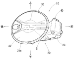
電気自動車(EV)、プラグインハイブリッド電気自動車(PHEV)等、外部電源により充電可能なバッテリを備える自動車は、図3に示されるように、バッテリを充電する際に電源側のコネクタが接続される充電コネクタ50を備える。充電コネクタ50は、樹脂製のインレットボックス20に収容されている。インレットボックス20は、図2に示されるように、組み立てられた樹脂製のインレットボックスアッセンブリ10(以下、単にアッセンブリという)の一部を構成する。アッセンブリ10は、図1に示されるように、車両のアウタパネル2の側面の所定位置に取付けられる。以下の説明において、前後、左右、上下はそれぞれ車両の前後、左右、上下を意味するものとする。
アッセンブリ10は、図2及び図3に示されるように、開口22を有する樹脂製のインレットボックス20と、インレットボックス20の開口22を開閉する樹脂製の蓋30(リッド)と、インレットボックス20に対して蓋30を回動可能に連結するヒンジ機構40と、を備える。
インレットボックス20は、図6及び図7に示されるように、充電用コネクタ50を収容するボックス本体部21と、ボックス本体部21の側面前部から前方に張り出す張出し部23とから構成される。ボックス本体部21は略カップ状に形成されている。張出し部23は、ボックス本体部21側で開放した略角形(図2参照)の袋状に形成されている。
ボックス本体部21内の上側面には、図3に示されるように、充電用コネクタ50を照らす照明器具27が設けられている。照明器具27は、図4に示されるように、照明器具27の点灯及び消灯を切り替えるスイッチ28を備えている。ボックス本体部21内の後部上面には、図3に示されるように、蓋30を開く際に蓋30の回動自由端側を押圧する押圧機構60(プッシュリフタ)が設けられている。ボックス本体部21内の底部には、図5に示されるように、ボックス本体部21に収容された充電用コネクタ50に接続されるケーブル(図示省略)が通される床面開口21hが形成されている。
インレットボックス20の開口22の周縁には、円形のフランジ部21fが形成されている。フランジ部21fの周縁に沿ってゴム製のシール材21eが装着されている。フランジ部21fの裏側には、図5に示されるように、インレットボックス20を車両のアウタパネル2に取付けるためのボルト215がフランジ部21fの裏面に対してほぼ直角に突出するように形成されている。ボルト215は、ボックス本体部21に対して上側と下側のそれぞれに二本づつ配置されるように、フランジ部21fの周方向に約90°間隔で設けられている。
車両のアウタパネル2には、図5及び図6に示されるように、アッセンブリ10の蓋30等が収容される円形の窪み2kが形成されている。窪み2kの底の位置には、インレットボックス20が挿入される略十字形の穴部2jが形成されている。穴部2jの周縁2f、即ち窪み2kの底の位置には、図5に示されるように、インレットボックス20のフランジ部21fに設けられた各ボルト215が挿通されるボルト孔2bが形成されている。インレットボックス20を車両に取付けるには、まず、インレットボックス20をアウタパネル2の穴部2jに挿入して、図5に示されるように、インレットボックス20の四本のボルト215をアウタパネル2のボルト孔2bに通す。次に、アウタパネル2の内側から各々のボルト215にナットNを締め付ける。
蓋30は、図3に示されるように、円板状の蓋本体32と、蓋本体32を支持する平面略U字形のレバー35と、を備える。蓋本体32は、図6及び図7に示されるように、インレットボックス20のフランジ部21fとほぼ等しい外径寸法に設定されており、アウタパネル2の円形の窪み2kに収容されるように構成されている。蓋本体32は、インレットボックス20のフランジ部21fと同軸に配置された状態でインレットボックス20の開口22を塞ぐ。蓋本体32は、表面板部32fと裏面板部32uとが合わせられることにより構成されている。裏面板部32uの中央位置には、充電用コネクタ50のカバー部32cが形成されている。レバー35は、蓋30の回動が許容されるようにインレットボックス20の張出し部23内に収容されている。レバー35の回動自由端側は、蓋本体32の裏面板部32uの前端部分に連結されている。
ヒンジ機構40は、インレットボックス20に対して蓋30をほぼ水平に回動可能に連結する機構である。ヒンジ機構40は、バネ(図示省略)を備え、バネの付勢力で蓋30を全閉位置、あるいは全開位置に保持できる。ヒンジ機構40は、図5に示されるように、ヒンジピン41を備える。インレットボックス20の張出し部23内における前端右側の上壁部と下壁部には、ヒンジピン41の各端部が通される上側軸受部23jと下側軸受部(図示省略)とがそれぞれ形成されている。
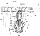
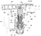
押圧機構60は、蓋30を開く際、図7及び図11に示されるように蓋30の回動自由端側をインレットボックス20内から押圧するとともに、照明器具27のスイッチ28(図4参照)をオン動作させる。押圧機構60は、図8及び図11に示されるように、押圧機構本体61と、スイッチ28の動作部70と、を備える。
押圧機構本体61は、図8及び図11に示されるように、閉じた蓋本体32に対して垂直となる状態でボックス本体部21に取付けられるガイド筒62を備える。ガイド筒62は、軸方向から嵌め合わされる外筒62tと内筒62eを備える。外筒62tの一端側は、ボックス本体部21に固定されている。
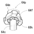
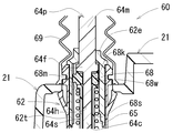
ガイド筒62内には、軸部材64が軸方向に摺動可能に収容されている。軸部材64は、図8及び図11に示されるように、内筒62e側の開口(同図中、上側の開口)から突出する蓋押圧軸64pと、外筒62t側の開口(同図中、下側の開口)から突出するスイッチ押圧軸64sと、を備える。蓋押圧軸64pは、図9に示されるように、軸部本体64mと、フランジ部64fと、小径の連結軸部64cと、を備える。軸部本体64mとフランジ部64fと小径の連結軸部64cは、同軸に設けられている。蓋押圧軸64pの連結軸部64cがスイッチ押圧軸64sの連結孔64hに嵌め込まれて、両押圧軸64p,64sが同軸に連結されている。押圧機構本体61には、軸部材64の移動を妨げないようにしつつ蓋押圧軸64pの突出部分を覆うジャバラ状の保護カバー69が設けられている。
ガイド筒62内における軸部材64のスイッチ押圧軸64sの周囲には、図8及び図11に示されるように、コイルバネ65が装着されている。コイルバネ65は、軸部材64をガイド筒62の内筒62e側の開口(上側の開口)から突出させるように付勢する。
ガイド筒62の内筒62eと軸部材64の蓋押圧軸64pとの間には、規制機構68が設けられている。規制機構68は、蓋押圧軸64pの押圧動作を規制可能で且つ該規制を解除可能である。規制機構68は、図12に示されるように、蓋押圧軸64pの連結軸部64cの周囲に回動可能に装着されたリング部材68wを備える。
蓋押圧軸64pのフランジ部64fの片面(図12において下面)には、図10に示されるように、波形の傾斜面68kが形成されている。リング部材68wの軸方向における一端面(図12において上面)には、蓋押圧軸64pの波形の傾斜面68kに沿って摺動可能な傾斜面(図示省略)が形成されている。リング部材68wが蓋押圧軸64pのフランジ部64fに押されて蓋押圧軸64pと共に軸方向に移動する毎に、傾斜面68k等の摺動作用によって、リング部材68wは蓋押圧軸64pの連結軸部64cの回りを一定角度だけ回動する。
ガイド筒62の内筒62eの内周面には、ガイド溝68mと係合溝68sとが形成されている。ガイド溝68mは内筒62eの軸方向一端部から他端部まで形成されており、係合溝68sは内筒62eの一端部(ガイド筒62の中央部分)に形成されている。リング部材68wは、外周面に外周爪(図示省略)を備える。外周爪は、ガイド溝68m及び係合溝68sのいずれにも嵌合可能である。図8には外周爪が係合溝68sと嵌合した状態が、図12には外周爪がガイド溝68mと嵌合した状態が示されている。ガイド溝68m及び係合溝68sは、一定角度間隔で交互に形成されている。リング部材68wが一定角度回動する毎に、リング部材68wの外周爪がガイド溝68m又は係合溝68sと交互に嵌合する。
図11に示される状態で、軸部材64がコイルバネ65の付勢力に抗して軸方向に押し込まれると、リング部材68wの外周爪が内筒62eのガイド溝68mに沿って移動する。リング部材68wの外周爪がガイド溝68mから外れた時点で、リング部材68wが蓋押圧軸64pの傾斜面68kの作用により一定角度だけ回動する。これにより、リング部材68wの外周爪が係合溝68sの位置に合わせられる。次に、軸部材64の押し込み力が除去されると、コイルバネ65の付勢力でリング部材68wが移動して外周爪が係合溝68sと係合し、押圧機構本体61は軸部材64が押し込まれた状態に保持される(図8参照)。
図8に示される状態で、軸部材64がコイルバネ65の付勢力に抗して軸方向に押し込まれると、リング部材68wの外周爪が内筒62eの係合溝68sから外れ、リング部材68wが蓋押圧軸64pの傾斜面68kの働きで一定角度だけ回動する。これにより、リング部材68wの外周爪がガイド溝68mの位置に合わせられる。次に、軸部材64の押し込み力が除去されると、コイルバネ65の付勢力でリング部材68wの外周爪がガイド溝68mに沿って移動する。この間、軸部材64はリング部材68wと共に移動してガイド筒62から蓋30を押圧する方向に突出する。こうして、押圧機構本体61は軸部材64が突出した状態に保持される(図11参照)。
スイッチ28の動作部70は、図8及び図11に示されるように、ハウジング72と、ハウジング72内を移動可能であってスイッチ動作レバー74(可動部)と、を備える。ハウジング72は、インレットボックス20の裏側に位置するガイド筒62(外筒62t)の他端側に取付けられている。スイッチ動作レバー74は、スイッチ押圧軸64sに連結されている。詳しくは、スイッチ動作レバー74は、図8及び図11に示されるようにハウジング72とスイッチ操作レバー74との間に設けられたバネにより付勢されている。
図8に示されるように、蓋30が閉じられて軸部材64が押し込まれると、ガイド筒62に対するスイッチ押圧軸64sの突出量が大きくなる。突出量が最大となるとスイッチ動作レバー74が図8において下限位置に保持される。スイッチ動作レバー74のオフ動作により、スイッチ28がオフになり照明器具27が消灯する。
図11に示されるように、蓋30が開けられて軸部材64が突出すると、ハウジング72とスイッチ操作レバー74との間に設けられたバネの作用により、ガイド筒62に対するスイッチ押圧軸64sの突出量が小さくなる。突出量が最小になるとスイッチ動作レバー74が図11において上限位置に保持される。スイッチ動作レバー74のオン動作により、スイッチ28がオンになり照明器具27が点灯する。
図6及び図8に示されるように、アッセンブリ10の蓋30が閉じられている状態では、軸部材64が押し込まれた状態に保持されており、スイッチ28がオフ状態で照明器具27が消灯している。さらに、アッセンブリ10の蓋30は、ヒンジ機構40のバネ(図示省略)の付勢力で全閉位置に保持されている。
アッセンブリ10の蓋30を開くには、作業者はまず蓋30を閉じ方向に押圧して、蓋30により押圧機構60(押圧機構本体61)の軸部材64を押し込む。これにより、リング部材68wの外周爪が内筒62eの係合溝68sから外れる。これにより、リング部材68wが軸部材64の傾斜面68kの作用で一定角度回動し、リング部材68wの外周爪が内筒62eのガイド溝68mの位置に合わされる。
次に、作業者が蓋30から手を離すと、これにより、コイルバネ65の付勢力でリング部材68wの外周爪がガイド溝68mに沿って移動するとともに、軸部材64がガイド筒62から蓋30を押圧する方向に突出する(図7及び図11参照)。これにより、蓋30が一定量開かれるとともに、スイッチ28がオンになり照明器具27が点灯する。この状態で、蓋30を持って全開位置まで開放できる。また、照明器具27が点灯することで、暗い位置であっても電源側コネクタ(図示省略)を充電用コネクタ50に接続し易くなる。
アッセンブリ10の蓋30を閉じるには、作業者はまず全開状態の蓋30をヒンジ機構40のバネ(図示省略)の付勢力に抗して図11の全閉近傍位置まで閉じる。作業者は次に、蓋30を閉じ方向に押圧して、蓋30により軸部材64を押し込む。これにより、リング部材68wの外周爪が内筒62eのガイド溝68mから外れる。これにより、リング部材68wが軸部材64の傾斜面68kの作用で一定角度回動し、リング部材68wの外周爪が内筒62eの係合溝68sの位置に合わされる。
次に、作業者が蓋30から手を離すと、これにより、コイルバネ65の付勢力でリング部材68wの外周爪が係合溝68sと係合する。軸部材64が押し込まれた状態に保持されるとともに、スイッチ28がオフになり照明器具27が消灯する。蓋30はヒンジ機構40のバネ(図示省略)の付勢力により全閉位置に保持される。
以上に説明したように、アッセンブリ10は、車両のアウタパネル2に取付けられる開口22を有するインレットボックス20と、インレットボックス20の開口22を開閉する蓋30と、蓋30をインレットボックス20に連結するヒンジ機構40と、を有する。さらにアッセンブリ10は、蓋30をインレットボックス20内から開方向に押圧する押圧機構60と、インレットボックス20内に設けられた照明器具27と、オン動作により照明器具27を点灯させオフ動作により照明器具27を消灯させるスイッチ28と、を有する。スイッチ28は、押圧機構60が蓋30を開方向に押圧する動作に連動してオン動作し、蓋30が閉操作されて押圧機構60が押し込まれる動作に連動してオフ動作する。
このように、充電作業等、インレットボックス20に関わる作業の際に、作業者が蓋30に触れて開操作することで、押圧機構60が蓋30を開方向に押圧し照明器具27のスイッチ28がオンになるため、作業が行われるときにのみインレットボックス20内の照明器具27が点灯する。また、作業が完了して作業者が蓋30を閉操作すると照明器具27が消灯するため、照明器具27の点灯時間が必要最小限になり、バッテリ電力の無駄が生じない。
また、スイッチ28は作業者が直接的に操作して照明器具27を点灯させるものではないため、スイッチ28をインレットボックス20内において作業者の操作可能な位置に設ける必要がない。このため、スイッチ28の配置の自由度が向上し、スイッチ28を設けることでインレットボックス20の開口面積を大きくする必要がなくなる。
具体的には、スイッチ28は、オン動作及びオフ動作する可動部を有する。押圧機構60は、軸部材64とガイド筒62とバネ65とを有する。軸部材64は、軸方向の一端部(蓋押圧軸64p)で蓋30を押圧し且つ軸方向の他端部(スイッチ押圧軸64s)でスイッチ28の可動部(スイッチ動作レバー74)を押圧する。ガイド筒62は、インレットボックス20に取付けられ軸部材64を軸方向に摺動可能に支持する。バネ65は、ガイド筒62に対して軸部材64を蓋30の押圧方向に付勢する。このように、スイッチ28が押圧機構60と重なる位置に設けられているため、スイッチ28を設けることでインレットボックス20の開口面積が大きくならない。
押圧機構60は、規制構造68(規制構造)を有する。規制機構68は、蓋30の閉操作時に軸部材がバネ65の付勢力に抗して所定位置まで押し込まれた際、軸部材64の押圧動作を規制する。また規制構造68は、蓋30の開操作時に蓋30が閉じた位置からさらに閉方向に押圧されて軸部材64が所定位置から押し込まれた際、軸部材64の押圧動作の規制を解除する。これにより、軸部材64は蓋30を開操作するときにのみ蓋30を押圧するため、蓋の開操作が容易になる。
インレットボックス内には、車両のバッテリを充電する際に電源側コネクタが接続される充電用コネクタが設けられているため、充電作業の際に上述の各効果が得られる。
本発明の形態を上記の構造を参照して説明したが、本発明の目的を逸脱せずに多くの交代、改良、変更が可能であることは当業者であれば明らかである。したがって本発明の形態は、添付された請求項の精神と目的と逸脱しない全ての交代、改良、変更を含み得る。例えば、本発明の形態は、前記の特別な構造に限定されず、下記のように変更が可能である。
軸部材64を構成する蓋押圧軸64pとスイッチ押圧軸64sは、本実施形態のように別体とするのみならず、蓋押圧軸64pとスイッチ押圧軸64sとを一体成形することも可能である。
アッセンブリ10は、充電用コネクタ50に代えて給油口を備えるものとすることも可能である。
Claims (4)
- 車両のインレットボックスアッセンブリであって、
前記車両のアウタパネルに取付けられる開口を有するインレットボックスと、前記インレットボックスの前記開口を開閉する蓋と、前記蓋を前記インレットボックスに連結するヒンジ機構と、前記蓋を前記インレットボックス内から開方向に押圧する押圧機構と、前記インレットボックス内に設けられた照明器具と、前記照明器具をオン動作により点灯させかつ前記照明をオフ動作により消灯させるスイッチを有し、
前記スイッチは、前記押圧機構が前記蓋を開方向に押圧する動作に連動して前記オン動作し、前記蓋が閉操作されて前記押圧機構が押し込まれる動作に連動して前記オフ動作するように構成された車両のインレットボックスアッセンブリ。 - 請求項1に記載の車両のインレットボックスアッセンブリであって、
前記スイッチは、前記オン動作及び前記オフ動作する可動部を有し、
前記押圧機構は、軸方向の一端部で前記蓋を押圧し且つ軸方向の他端部で前記スイッチの前記可動部を押圧する軸部材と、前記インレットボックスに取付けられ前記軸部材を軸方向に摺動可能に支持するガイド筒と、前記ガイド筒に対して前記軸部材を前記蓋の押圧方向に付勢するバネを有する車両のインレットボックスアッセンブリ。 - 請求項2に記載の車両のインレットボックスアッセンブリであって、
前記押圧機構は、前記蓋の閉操作時に前記軸部材が前記バネの付勢力に抗して所定位置まで押し込まれた際前記軸部材の押圧動作を規制しかつ前記蓋の開操作時に前記蓋が閉じた位置からさらに閉方向に押圧されて前記軸部材が前記所定位置から押し込まれた際前記軸部材の前記押圧動作の規制を解除する規制構造を有する車両のインレットボックスアッセンブリ。 - 請求項1から請求項3のいずれか一つに記載の車両のインレットボックスアッセンブリであって、
前記車両のバッテリを充電する際に電源側コネクタが接続される充電用コネクタが前記インレットボックス内に設けられている車両のインレットボックスアッセンブリ。
Applications Claiming Priority (2)
| Application Number | Priority Date | Filing Date | Title |
|---|---|---|---|
| JP2011-115780 | 2011-05-24 | ||
| JP2011115780A JP2012240645A (ja) | 2011-05-24 | 2011-05-24 | 車両のインレットボックスアッセンブリ |
Publications (1)
| Publication Number | Publication Date |
|---|---|
| WO2012161087A1 true WO2012161087A1 (ja) | 2012-11-29 |
Family
ID=47217165
Family Applications (1)
| Application Number | Title | Priority Date | Filing Date |
|---|---|---|---|
| PCT/JP2012/062662 Ceased WO2012161087A1 (ja) | 2011-05-24 | 2012-05-17 | 車両のインレットボックスアッセンブリ |
Country Status (2)
| Country | Link |
|---|---|
| JP (1) | JP2012240645A (ja) |
| WO (1) | WO2012161087A1 (ja) |
Cited By (7)
| Publication number | Priority date | Publication date | Assignee | Title |
|---|---|---|---|---|
| DE102016004557A1 (de) * | 2016-04-15 | 2017-10-19 | GM Global Technology Operations LLC (n. d. Gesetzen des Staates Delaware) | Klappe mit einem Anzeigemittel |
| US20210016658A1 (en) * | 2019-07-15 | 2021-01-21 | Illinois Tool Works Inc. | Charging or fueling recess and method for the production thereof |
| WO2021071704A1 (en) * | 2019-10-10 | 2021-04-15 | Illinois Tool Works Inc. | Charging or refuelling recess |
| US11124995B2 (en) * | 2018-02-28 | 2021-09-21 | Nifco Inc. | Push-lifter for vehicle |
| EP4140793A1 (de) * | 2021-08-27 | 2023-03-01 | Reich GmbH Regel- und Sicherheitstechnik | Klappeneinrichtung für ein fahrzeug |
| CN116783090A (zh) * | 2021-01-27 | 2023-09-19 | 浙江智马达智能科技有限公司 | 一种汽车充电口盖结构及汽车 |
| JP2023146184A (ja) * | 2022-03-29 | 2023-10-12 | 本田技研工業株式会社 | 燃料タンクの照明装置 |
Families Citing this family (6)
| Publication number | Priority date | Publication date | Assignee | Title |
|---|---|---|---|---|
| WO2014045831A1 (ja) * | 2012-09-19 | 2014-03-27 | 日産自動車株式会社 | 電動車両の外部充電構造 |
| JP5920146B2 (ja) * | 2012-09-27 | 2016-05-18 | 豊田合成株式会社 | フューエルインレットボックスのシール構造 |
| JP7086915B2 (ja) * | 2019-10-24 | 2022-06-20 | 株式会社ニフコ | リッド装置 |
| KR102327482B1 (ko) * | 2020-09-11 | 2021-11-17 | 대동하이렉스 주식회사 | 자동차 연료 주입구 도어 개폐장치 |
| KR20230087731A (ko) * | 2021-12-10 | 2023-06-19 | 에스엘 주식회사 | 충전 포트 도어 |
| FR3139515A1 (fr) * | 2022-09-08 | 2024-03-15 | Psa Automobiles Sa | Vehicule automobile avec prise de recharge de batterie de traction sur un panneau arriere de custode |
Citations (6)
| Publication number | Priority date | Publication date | Assignee | Title |
|---|---|---|---|---|
| JPH03121920U (ja) * | 1990-03-27 | 1991-12-12 | ||
| JPH06290836A (ja) * | 1993-03-31 | 1994-10-18 | Sumitomo Wiring Syst Ltd | 電気自動車における充電用コネクタ |
| JP2004281259A (ja) * | 2003-03-17 | 2004-10-07 | Alps Electric Co Ltd | プッシュスイッチ装置 |
| WO2007122835A1 (ja) * | 2006-04-25 | 2007-11-01 | Nifco Inc. | 押上装置 |
| JP2009146711A (ja) * | 2007-12-13 | 2009-07-02 | Mitsubishi Motors Corp | 充電コネクタの取付構造 |
| JP2011098632A (ja) * | 2009-11-05 | 2011-05-19 | Suzuki Motor Corp | 充電器冷却構造および車載機器冷却システム |
-
2011
- 2011-05-24 JP JP2011115780A patent/JP2012240645A/ja not_active Withdrawn
-
2012
- 2012-05-17 WO PCT/JP2012/062662 patent/WO2012161087A1/ja not_active Ceased
Patent Citations (6)
| Publication number | Priority date | Publication date | Assignee | Title |
|---|---|---|---|---|
| JPH03121920U (ja) * | 1990-03-27 | 1991-12-12 | ||
| JPH06290836A (ja) * | 1993-03-31 | 1994-10-18 | Sumitomo Wiring Syst Ltd | 電気自動車における充電用コネクタ |
| JP2004281259A (ja) * | 2003-03-17 | 2004-10-07 | Alps Electric Co Ltd | プッシュスイッチ装置 |
| WO2007122835A1 (ja) * | 2006-04-25 | 2007-11-01 | Nifco Inc. | 押上装置 |
| JP2009146711A (ja) * | 2007-12-13 | 2009-07-02 | Mitsubishi Motors Corp | 充電コネクタの取付構造 |
| JP2011098632A (ja) * | 2009-11-05 | 2011-05-19 | Suzuki Motor Corp | 充電器冷却構造および車載機器冷却システム |
Cited By (10)
| Publication number | Priority date | Publication date | Assignee | Title |
|---|---|---|---|---|
| DE102016004557A1 (de) * | 2016-04-15 | 2017-10-19 | GM Global Technology Operations LLC (n. d. Gesetzen des Staates Delaware) | Klappe mit einem Anzeigemittel |
| US11124995B2 (en) * | 2018-02-28 | 2021-09-21 | Nifco Inc. | Push-lifter for vehicle |
| US20210016658A1 (en) * | 2019-07-15 | 2021-01-21 | Illinois Tool Works Inc. | Charging or fueling recess and method for the production thereof |
| US11945300B2 (en) * | 2019-07-15 | 2024-04-02 | Illinois Tool Works Inc. | Charging or fueling recess and method for the production thereof |
| WO2021071704A1 (en) * | 2019-10-10 | 2021-04-15 | Illinois Tool Works Inc. | Charging or refuelling recess |
| CN116783090A (zh) * | 2021-01-27 | 2023-09-19 | 浙江智马达智能科技有限公司 | 一种汽车充电口盖结构及汽车 |
| EP4286256A4 (en) * | 2021-01-27 | 2024-11-06 | Zhejiang Smart Intelligence Technology Co., Ltd. | Automobile charging port cover structure, and automobile |
| EP4140793A1 (de) * | 2021-08-27 | 2023-03-01 | Reich GmbH Regel- und Sicherheitstechnik | Klappeneinrichtung für ein fahrzeug |
| JP2023146184A (ja) * | 2022-03-29 | 2023-10-12 | 本田技研工業株式会社 | 燃料タンクの照明装置 |
| JP7487249B2 (ja) | 2022-03-29 | 2024-05-20 | 本田技研工業株式会社 | 燃料タンクの照明装置 |
Also Published As
| Publication number | Publication date |
|---|---|
| JP2012240645A (ja) | 2012-12-10 |
Similar Documents
| Publication | Publication Date | Title |
|---|---|---|
| WO2012161087A1 (ja) | 車両のインレットボックスアッセンブリ | |
| US11519203B2 (en) | Actuation device | |
| US10328792B2 (en) | Lid device | |
| KR101577548B1 (ko) | 충전 포트 로크 장치 | |
| WO2012157489A1 (ja) | 車両のインレットボックスの取付け構造 | |
| CN108340974B (zh) | 充电盖单元 | |
| JP2014110205A (ja) | 充電ポートロック装置 | |
| US9631403B2 (en) | Actuation device for a flap | |
| JP2015207565A (ja) | 電動車両の充電ポート装置 | |
| JP2015074976A (ja) | ラッチ装置 | |
| US10124673B2 (en) | Reaction force output device | |
| US20120282806A1 (en) | Electric power connector | |
| US11426838B2 (en) | Rotating tool | |
| CN219569855U (zh) | 汽车车身盖的控制机构 | |
| JP6682364B2 (ja) | ハウジングユニット及び開閉体のロック装置 | |
| US10955053B2 (en) | Manual unlocking device for parking lock mechanism | |
| JP2016223256A (ja) | 車両用の蓋体開閉装置 | |
| US12590478B2 (en) | Lid opening/closing structure | |
| JP5355035B2 (ja) | 車両用リッドロック装置 | |
| JP2024532087A (ja) | 自動車用途の為のロック用アクチュエータ | |
| JP2012018838A (ja) | 車両側コネクタ | |
| JP7800382B2 (ja) | リッド開閉装置 | |
| KR20240017191A (ko) | 전기자동차용 아웃렛 충전기 | |
| US20240263506A1 (en) | Lid opening/closing device | |
| JP2015103379A (ja) | 車両側コネクタ |
Legal Events
| Date | Code | Title | Description |
|---|---|---|---|
| 121 | Ep: the epo has been informed by wipo that ep was designated in this application |
Ref document number: 12789892 Country of ref document: EP Kind code of ref document: A1 |
|
| DPE1 | Request for preliminary examination filed after expiration of 19th month from priority date (pct application filed from 20040101) | ||
| NENP | Non-entry into the national phase |
Ref country code: DE |
|
| 122 | Ep: pct application non-entry in european phase |
Ref document number: 12789892 Country of ref document: EP Kind code of ref document: A1 |