WO2012160988A1 - 流体制御装置 - Google Patents
流体制御装置 Download PDFInfo
- Publication number
- WO2012160988A1 WO2012160988A1 PCT/JP2012/062083 JP2012062083W WO2012160988A1 WO 2012160988 A1 WO2012160988 A1 WO 2012160988A1 JP 2012062083 W JP2012062083 W JP 2012062083W WO 2012160988 A1 WO2012160988 A1 WO 2012160988A1
- Authority
- WO
- WIPO (PCT)
- Prior art keywords
- horizontal frame
- line support
- fluid control
- frame member
- support member
- Prior art date
- Legal status (The legal status is an assumption and is not a legal conclusion. Google has not performed a legal analysis and makes no representation as to the accuracy of the status listed.)
- Ceased
Links
Images




Classifications
-
- F—MECHANICAL ENGINEERING; LIGHTING; HEATING; WEAPONS; BLASTING
- F16—ENGINEERING ELEMENTS AND UNITS; GENERAL MEASURES FOR PRODUCING AND MAINTAINING EFFECTIVE FUNCTIONING OF MACHINES OR INSTALLATIONS; THERMAL INSULATION IN GENERAL
- F16L—PIPES; JOINTS OR FITTINGS FOR PIPES; SUPPORTS FOR PIPES, CABLES OR PROTECTIVE TUBING; MEANS FOR THERMAL INSULATION IN GENERAL
- F16L3/00—Supports for pipes, cables or protective tubing, e.g. hangers, holders, clamps, cleats, clips, brackets
- F16L3/22—Supports for pipes, cables or protective tubing, e.g. hangers, holders, clamps, cleats, clips, brackets specially adapted for supporting a number of parallel pipes at intervals
-
- F—MECHANICAL ENGINEERING; LIGHTING; HEATING; WEAPONS; BLASTING
- F16—ENGINEERING ELEMENTS AND UNITS; GENERAL MEASURES FOR PRODUCING AND MAINTAINING EFFECTIVE FUNCTIONING OF MACHINES OR INSTALLATIONS; THERMAL INSULATION IN GENERAL
- F16K—VALVES; TAPS; COCKS; ACTUATING-FLOATS; DEVICES FOR VENTING OR AERATING
- F16K27/00—Construction of housing; Use of materials therefor
-
- F—MECHANICAL ENGINEERING; LIGHTING; HEATING; WEAPONS; BLASTING
- F16—ENGINEERING ELEMENTS AND UNITS; GENERAL MEASURES FOR PRODUCING AND MAINTAINING EFFECTIVE FUNCTIONING OF MACHINES OR INSTALLATIONS; THERMAL INSULATION IN GENERAL
- F16K—VALVES; TAPS; COCKS; ACTUATING-FLOATS; DEVICES FOR VENTING OR AERATING
- F16K27/00—Construction of housing; Use of materials therefor
- F16K27/003—Housing formed from a plurality of the same valve elements
-
- F—MECHANICAL ENGINEERING; LIGHTING; HEATING; WEAPONS; BLASTING
- F17—STORING OR DISTRIBUTING GASES OR LIQUIDS
- F17D—PIPE-LINE SYSTEMS; PIPE-LINES
- F17D1/00—Pipe-line systems
- F17D1/02—Pipe-line systems for gases or vapours
- F17D1/04—Pipe-line systems for gases or vapours for distribution of gas
Definitions
- the present invention relates to a fluid control device used in a semiconductor manufacturing apparatus or the like, and more particularly, to a fluid control device formed by integrating a plurality of fluid control devices.
- a plurality of fluid control devices are arranged in series, and a plurality of lines formed by connecting them without using pipes or joints are arranged in parallel on a base member. Integration is progressing in the area.
- An integrated fluid control device is often installed in a vertical state in a casing, and in Patent Document 1, as such a fluid control device, a plurality of fluid control devices are provided on one movable rail (line support member).
- a plurality of lines formed by being attached are disclosed, and each movable rail of the plurality of lines is slidably attached to a fixed rail (base member) that faces in a direction orthogonal thereto. ing.
- the structure is such that a plurality of large stresses (tensile stress, shear stress, etc.) are applied to the fastening member (bolt).
- the height of the portion that supports the fluid control device is the height of the movable rail (line support member) + the height of the fixed rail (base member).
- the height of a fluid control device including a fluid control device is increased, and a space (housing) for storing the fluid control device becomes large.
- An object of the present invention is to provide a fluid control device capable of shortening assembly time by facilitating fixing of a line support member.
- Another object of the present invention is to provide a fluid control device capable of suppressing an increase in the height of the portion supporting the fluid control device.
- a fluid control device is a fluid control device in which a plurality of fluid control devices are attached to one line support member, and the plurality of line support members are detachably attached to the base member.
- the frame member and the lower horizontal frame member and the left and right vertical frame members orthogonal to these are formed in a rectangular frame shape, and each horizontal frame member is provided with a positioning portion for positioning each line support member, The upper and lower end portions of each line support member are fixed in a state of being positioned by the positioning portions of the respective lateral frame members.
- the line support member to which the fluid control device is attached is attached in front of the fluid control device (FIG. 9), and the front, back, top, bottom, left and right are based on this.
- This state is a typical installation state of the fluid control device, but the fluid control device of the present invention is not limited to this installation state, and the base member formed in a rectangular frame shape is vertical (Y direction). ) And the base member formed in a rectangular frame shape may be installed horizontally (X direction, Z direction).
- the upper horizontal frame member may be arranged on either the left or right side, the lower horizontal frame member on the other side, and the line support members may be arranged in parallel so as to be parallel to each other.
- each line support member to each horizontal frame member may be performed, for example, by fitting both members or using a separate member (for example, a cover member).
- Each line support member is preferably sandwiched between each horizontal frame member and an upper and lower cover member that is detachably attached to the base member.
- each horizontal frame member is, for example, a recess formed on the upper surface of each horizontal frame member, and each line support member is positioned by fitting its upper and lower ends to the recesses of each horizontal frame member.
- the configuration for positioning is not limited to this, and the positioning portion of each horizontal frame member may be a convex portion, and the upper and lower end portions of each line support member may be provided with concave portions that fit into this. .
- Each horizontal frame member is provided with screw holes at least at both ends thereof, and the cover member is formed with screw member insertion holes at both ends thereof and is detachably attached to the horizontal frame member by male screw members. It is preferable.
- Each line support member is made of, for example, a sheet metal having a body portion with an inverted U-shaped cross section.
- Each horizontal frame member is, for example, a metal flat bar made of sheet metal or stainless steel having a substantially U-shaped cross section. When the horizontal frame member has a substantially U-shaped cross section, it is preferable that the horizontal frame member is disposed so as to open to the back side, and a concave portion is formed on the upper wall thereof.
- the vertical frame member is made of, for example, a sheet metal having a body portion with an inverted U-shaped cross section.
- the cover member is made of a sheet metal having a substantially L-shaped cross section, for example.
- Fluid control devices include on-off valves (valves that shut off and open fluid passages), pressure reducing valves, pressure and flow measurement and indicators, and flow regulators (flow control valves, thermal mass flow controllers such as mass flow controllers) A device, a pressure type flow rate control device, etc.).
- a plurality of block-shaped joint members which are lower layers, are attached to a line support member by male thread members, and a plurality of fluid control devices, which are upper layers so as to straddle adjacent joint members, It is attached to the joint member by a male screw member. If it does in this way, the fluid control apparatus of an upper layer can be taken out upwards independently by removing the external thread member from the upper part.
- the configuration of one line is not limited to that composed of a lower layer and an upper layer, and various configurations can be employed.
- the upper and lower cover members may be fixed to the base member (horizontal frame member or vertical frame member) with bolts or the like.
- the weight of the line support member can be supported by the upper horizontal frame member, the weight burden on the operator is reduced, the labor and time of work are reduced, and each line support member is Since it is fixed, the labor is eliminated and the assembly time can be greatly shortened.
- Each line support member has a flat plate-like device placement portion and an upper bent portion that is bent to the back side at the upper end side, and the upper and lower end portions of the device placement portion are in front of each horizontal frame member. It is preferable that the upper bent portion is in contact with the upper surface of the upper horizontal frame member.
- the upper bent portion of the line support member is received by the upper surface of the upper horizontal frame member, so that the weight of the line support member is supported by the upper horizontal frame member, and the fluid control device in the fluid control device is An increase in the height of the supporting portion can be suppressed.
- a convex portion extending downward is provided at the upper bent portion of each line support member, and concave portions into which the convex portions of the upper bent portion can be fitted are formed on the upper surface of the upper horizontal frame member at a required interval. It is preferable.
- the convex part of the upper bent part is, for example, that the rear side end of the upper bent part is bent at a right angle to the lower side and the lateral width thereof is shortened.
- the shape of the convex portion can be various shapes, and the shape of the concave portion of the upper horizontal frame member is determined according to this shape.
- the convex portion of the upper bent portion may be fitted into the concave portion of the upper horizontal frame member from above (using its own weight). It can be done easily.
- the recesses of the upper horizontal frame member are provided at an interval smaller than the pitch of the line support member arrangement, and the line support member can be positioned by using a plurality of recesses, one by two, etc. It is more preferable that it is made like this.
- Each line support member further has a left and right bent portion that is bent to the back side at the left and right edges of the device mounting portion, and the lower end of the left and right bent portion is fitted on the upper surface of the lower horizontal frame member. It is preferred that possible recesses are formed at the required intervals.
- the upper and lower ends of the left and right bent parts are notched so that the vertical length is shorter than the vertical length of the equipment placement section, and the upper and lower ends of the equipment placement section are in contact with the upper surfaces of the vertical horizontal frame members.
- both the upper bent portion and the convex portion of the upper bent portion are fitted into the concave portion of the upper horizontal frame member from above so that the upper and lower horizontal frame members do not interfere with each other.
- the width in the left-right direction of the concave portion of the lower horizontal frame member is such that both one of the left bent portion and the other right bent portion of the adjacent line support member can be fitted in one concave portion of the lower horizontal frame member. It is preferable that
- the width in the left-right direction of the concave portion of the lower horizontal frame member may be twice the plate thickness of each line support member. If it does in this way, while adjacent line support members can be arranged without a gap, play of each line support member can be controlled, and the full width of the device in the left-right direction can be reduced.
- the recesses of the lower horizontal frame member are also provided at intervals smaller than the pitch of the line support member arrangement, and the line support member can be positioned by using a plurality of recesses one by two, for example. It is preferable to be able to do this. More preferably, the width in the left-right direction of the recess of the upper horizontal frame member is made equal to the width of the recess in the upper horizontal frame member.
- the base member is formed in a rectangular frame shape by the upper horizontal frame member, the lower horizontal frame member, and the left and right vertical frame members orthogonal to them, and each horizontal frame member has a Positioning portions for positioning the line support members are provided, and the upper and lower end portions of each line support member are fixed in a state where they are positioned by the positioning portions of each horizontal frame member. Fixing work with bolts or the like is unnecessary, and the assembly time can be greatly shortened.
- a positioning structure between the line support member and each horizontal frame member (For example, positioning by fitting the convex portion and the concave portion) and a fixing structure (a structure in which the line support member is fixed by the upper and lower cover members) are divided, and thereby stress applied to the male screw member for attaching the upper and lower cover members. Is only stress generated when the line support member is fixed by the upper and lower cover members, and unnecessary stress is not applied to the male screw member.
- Each line support member has a flat device mounting portion and an upper bent portion that is bent to the back side at the upper end side thereof, and the upper and lower end portions of the device mounting portion are formed by the horizontal frame members. It is made to contact
- FIG. 1 is a perspective view showing a main part of an embodiment of a fluid control apparatus according to the present invention with a cover member omitted.
- FIG. 2 is a perspective view showing a main part of an embodiment of the fluid control apparatus according to the present invention including a cover member.
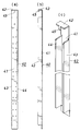
- 3A and 3B show a line support member of the fluid control apparatus according to the present invention, in which FIG. 3A is a partially cutaway front view, FIG. 3B is a side view thereof, and FIG. 4A and 4B are views showing an upper horizontal frame member used in the fluid control apparatus according to the present invention, in which FIG. 4A is a partially cutaway plan view, and FIG. 4B is a cross section taken along line bb in FIG. (C) is a partially cutaway front view.
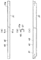
- FIG. 5A and 5B are views showing a lower horizontal frame member used in the fluid control apparatus according to the present invention, in which FIG. 5A is a partially cutaway plan view, and FIG. 5B is a cross section taken along line bb in FIG. (C) is a partially cutaway front view.
- 6A and 6B are views showing a lower cover member used in the fluid control apparatus according to the present invention.
- FIG. 6A is a partially cutaway plan view
- FIG. 6B is a sectional view taken along line bb in FIG. (C) is a partially cutaway front view.
- FIG. 7 is a perspective view showing a positioning configuration of each line support member and each horizontal frame member.
- FIG. 8 is a partially cutaway vertical cross-sectional view of the main part of the fluid control apparatus according to the present invention.
- FIG. 9 is a front view showing a comparative example of the fluid control apparatus according to the present invention.
- FIG. 10 is a side view of the same.
- Base member (31) Upper horizontal frame member (32) Lower horizontal frame member (33) (34) Left and right vertical frame members (36) (37) Upper and lower cover members (40) Line support member (41) Equipment placement section (42) Upper bent part (43) (44) Left and right bent part (45) Convex (46) Concave part (positioning part) (47) Concave part (positioning part)
- top / bottom / left / right refers to the top / bottom / left / right of FIG. 9, and for front / back (front and back), the front side of FIG. 9 is the front (front), and the back side of FIG. Let's say.
- FIG. 9 and FIG. 10 show an example (comparative example) of a fluid control device targeted by the present invention.
- the fluid control device (1) includes a plurality of block-shaped joint members (4), which are lower layers, attached to the line support member (3), and a plurality of fluids, which are upper layers so as to straddle adjacent joint members (4).
- the control device (5) has a plurality of lines formed by being attached to the joint member (4), and is attached to and detached from the base member (2) so that each line support member (3) is parallel to each other It is attached as possible.
- Each fluid control device (5) has a different function, but since it is a well-known device, it is generically referred to by reference numeral (5), and individual description is omitted.
- the base member (2) is fixed to, for example, a vertical wall surface of the casing, and the line support member (3) incorporating the joint member (4) and the fluid control device (5) can be changed or expanded. It is done by attaching and detaching.
- the base member (2) includes an upper horizontal frame member (11) arranged on the upper side and a lower horizontal frame member (12) arranged on the lower side, and a left vertical frame member (13) and a right vertical frame orthogonal to them.
- a square frame is formed by the member (14).
- Each fluid control device (5) is fixed to a corresponding joint member (4) by a male screw member from above.
- Each joint member (4) is fixed to the line support member (3) by a male screw member from above.
- Each horizontal frame member (11) (12) is a stainless steel flat bar, and each horizontal frame member (11) (12) is provided with a plurality of screw holes penetrating up and down at a required interval. It has been.
- the line support member (3) is formed as an integrated product by bending a sheet metal, and has a flat plate-like device placement portion (21) and flat plate-like device placement portions (21 ) The upper and lower ends of the upper and lower ends are bent so that the upper and lower mounting portions (22) and (23) are bent, and the reinforcing portion (24) is connected to both edges of the device placement portion (21). Become.
- the bent shape of the upper and lower end portions of the device mounting portion (21) is formed by bending the sheet metal, such as forming a bent shape with a plurality of members in addition to bending the sheet metal.
- Any configuration may be used as long as the same effects as in (23) can be obtained.
- Each mounting portion (22) (23) of the line support member (3) includes a flat plate portion (22a) (23a) formed in a flat plate shape that is flush with the end portion of the device placement portion (21).
- the right-angled portions (22b) and (23b) are substantially L-shaped, and the right-angled portions (22b) and (23b) are provided with through-holes (25) and (26) penetrating in the vertical direction. ing.
- the right angle portion (22b) of the upper mounting portion (22) is superimposed on the upper surface (outer surface) of the upper horizontal frame member (11), and the male screw member (10) is connected to the upper mounting portion ( 22)
- the upper end portion is fixed to the upper horizontal frame member (11) by being screwed into the screw hole of the upper horizontal frame member (11) from above (outside) the right angle portion (22b)
- the right angle portion (23b) of the lower mounting portion (23) is superimposed on the lower surface (outer surface) of the lower horizontal frame member (12), and the male screw member (10) is aligned with the right angle portion (23b) of the lower mounting portion (23).
- the lower end portion of the lower horizontal frame member (12) is fixed to the lower horizontal frame member (12) by being screwed into the screw hole of the lower horizontal frame member (12) from below (outside).
- each line support member (3) When fixing each line support member (3), the positioning of each line support member (3) is carried out through the through holes (25) (26) of the mounting portions (22) (23) and the horizontal frame members (11). Since it is only necessary to match the screw hole (15) of (12), it can be performed easily and easily, and the assembly time can be shortened. Further, the right angle portions (22b) and (23b) of the attachment portions (22) and (23) formed in a bent shape of the respective line support members (3) are overlapped on the outer surfaces of the respective lateral frame members (11) and (12). Therefore, the total height of the base member (2) (horizontal frame members (11) and (12)) and the line support member (3) is the height of the base member (2) + the height of the line support member (3).
- the height of the fixed rail (base member) of the conventional structure + the movable rail (line support) can be made lower than the height of the member.
- each line support member (3) With a male screw member (10), and there is a problem that it takes time and effort (the same applies to the device of Patent Document 1). There's a problem.).
- the fluid control device according to the present invention eliminates the trouble of fixing each line support member (3) to the fluid control device (1) shown in FIG. 9 and FIG.
- illustration of the joint member (4) and the fluid control device (5) is omitted, and only the support means including the base member (30), the line support member (40), and the cover members (36) (37) is illustrated. I will explain.
- the base member (30) includes an upper horizontal frame member (31) and a lower horizontal frame member (32), and a left vertical frame member (33) and a right vertical frame member ( 34) and the upper and lower ends of each vertical frame member (33) (34) are fixed to the left and right ends of each horizontal frame member (31) (32) by a male screw member (35) such as a bolt.
- a male screw member (35) such as a bolt.
- each horizontal frame member (31) (32) has a configuration for positioning each line support member (40) (a recess (not shown in the figure) of the upper horizontal frame member (31)) and a lower A recess (47) of the horizontal frame member (32) is provided.
- a wide member in addition to the narrow member (constituting one line) indicated by reference numeral (40), a wide member (constituting four lines) is also used. A space for installing an additional line is secured on the right side of the base member (30).
- Each line support member (40) is not fixed to each horizontal frame member (31) (32) by a screw member such as a bolt, but as shown in FIG. 2, the upper and lower cover members (36) ( 37) is fixed by being fastened to the horizontal frame members (31) and (32) by male screw members (38) such as bolts.
- each line support member (40) includes a flat plate-like device mounting portion (41), an upper bent portion (42) bent to the back side at the upper end side, and the device mounting. Left and right bent portions (43) and (44) bent to the back side at both left and right edges of the portion (41).
- the upper bent part (42) is rectangular and horizontal, and a substantially square convex part (45) extending downward is provided on the back face part.
- the left and right bent parts (43) and (44) are rectangular vertically long and perpendicular to the equipment mounting part (41), and are vertically longer than the vertical length of the equipment mounting part (41). Has been shortened.
- the convex portion (45) is formed such that the rear side end portion of the upper bent portion (42) is bent at a right angle downward and the lateral width thereof is shortened.
- the wide line support member constituting the four lines is basically the same shape as that of FIG.
- the part has a shape in which no convex part is provided, or a shape in which convex parts are provided at regular intervals.
- the upper horizontal frame member (31) has a substantially U-shaped cross-section opening on the back side, and the upper wall (31a) of the upper horizontal frame member is line-supported on the back side.
- a substantially rectangular recess (46) into which the protrusion (45) of the upper bent portion (42) of the member (40) can be fitted is formed at a required interval.
- the lower horizontal frame member (32) has a substantially U-shaped cross section that opens to the back side, like the upper horizontal frame member (31).
- substantially rectangular recesses (47) are formed at the same intervals as the recesses (46) of the upper horizontal frame member (31).
- the recess (47) is formed over the entire length of the upper wall (32a) in the front-rear direction, whereas the recess (46) of the upper horizontal frame member (31) is provided only on the back side.
- the lower end portions of the left and right bent portions (43) and (44) of the line support member (40) can be fitted into the concave portion (47).
- the lower cover member (37) (the upper cover member (36) has the same shape) has an L-shaped cross section composed of a vertical wall portion (37a) and a horizontal wall portion (37b).
- the wall (37a) is provided with a through hole (bolt insertion hole) (48).
- the convex portion (45) of the upper bent portion (42) of the line support member (40) is formed in the concave portion (46) provided on the upper surface (upper wall (31a)) of the upper horizontal frame member (31).
- the lower end of the left and right bent parts (43) and (44) of the line support member (40) in the recessed part (47) provided on the upper surface (upper wall (32a)) of the lower horizontal frame member (32). Is inserted.
- the left and right bent parts (43) and (44) of the line support member (40) are arranged when the upper and lower end parts of the equipment mounting part (41) are in contact with the front of the upper and lower horizontal frame members (31) and (32).
- the upper and lower horizontal frame members (31) and (32) Do not interfere with the upper and lower horizontal frame members (31) and (32) when fitting the convex portion (46) of the bent portion (42) into the concave portion (46) of the upper horizontal frame member (31) from above. Further, the upper end is positioned below the upper end of the device placement portion (41), and the lower end is positioned above the lower end of the device placement portion (41).
- the upper and lower end portions of the device mounting portion (41) are brought into contact with the front surfaces of the horizontal frame members (31) and (32), and the upper bent portion (42) is the upper horizontal frame member. It is brought into contact with the upper surface of (31).
- the upper bent portion (42) of the line support member (40) is received on the upper surface of the upper horizontal frame member (31), so that the weight of the line support member (40) is reduced by the upper horizontal frame member (31). It is supported.
- each line support member (40) when positioning each line support member (40), the convex portion (45) of the upper bent portion (42) of the line support member (40) from above to the concave portion (46) of the upper horizontal frame member (31) (
- Each line support member (40) can be easily positioned because it is only necessary to fit them using their own weight.
- the left and right bent parts (43) and (44) reinforce the equipment mounting part (41), and the position of each line support member (40) is determined by positioning using the bent parts. Both securing and simplification of the configuration are compatible.
- the combined height of the base member (30) (horizontal frame members (31) and (32)) and the line support member (40) is the base member (30 ) Height + line support member (40) height, not the base member (30) height + line support member (40) equipment mounting part (41) height (thickness).
- the height of the portion that supports the fluid control device in the fluid control device can be reduced. The increase can be suppressed.
- the left and right widths of the recesses (47) of the lower horizontal frame member (32) are twice the thickness of one of the left and right bent portions (43) and (44) of each line support member (40). Therefore, one left bent part (43) and the other right bent part (44) of the adjacent line support member (40) can be fitted into one concave part (47) of the lower horizontal frame member (32). It is said that.
- the upper cover member (36) has its horizontal wall portion (36b) applied to the upper surface of the upper wall (31a) of the upper horizontal frame member (31), and its vertical wall.
- the part (36a) is applied to the front of the upper end of the line support member (40)
- the lower cover member (37) has a horizontal wall part (37b) which is the lower wall (lower surface) of the lower horizontal frame member (32).
- the vertical wall portion (37a) is applied to the lower end portion of the line support member (40).
- the line support members to which the required fluid controllers are attached are sequentially attached.
- the convex portions (45) of the upper bent portions (42) of the respective line support members (40). ) Is fitted into the recess (46) of the upper horizontal frame member (31), and the lower ends of the left and right bent portions (43) and (44) are fitted into the recess (47) of the lower horizontal frame member (32).
- Positioning is performed.
- the upper and lower cover members (36), (37) are attached to the horizontal frame members (31), (32) by the male screw members (38). Install.
- each line support member (40) is sandwiched between the upper and lower horizontal frame members (31) (32) and the upper and lower cover members (36) (37), and each line support member to which the fluid controller is attached ( 40) is fixed to the base member (30). Therefore, at the time of positioning each line support member (40), fixing work with bolts or the like is unnecessary, and the assembly time can be greatly shortened. Also, when adding, changing, and maintaining the line, remove the upper and lower cover members (36), (37), remove the required line support member (40), add a new line support member (40), etc. The upper and lower cover members (36) and (37) may be attached, and the time for extension, change and maintenance of the line can be shortened.
- the left and right bent portions (43) and (44) can reinforce the device mounting portion (41) even if they are not perpendicular to the device mounting portion (41), and support multiple lines.
- any shape may be used as long as they do not interfere with the adjacent line support member (40). In that case, the concave shape of the lower horizontal frame member (32) may be changed accordingly.
- the present invention is suitable for use in a fluid control device formed by integrating a plurality of fluid control devices.
- the assembly time can be shortened, and an increase in the height of the portion supporting the fluid control device can be suppressed.
Landscapes
- Engineering & Computer Science (AREA)
- General Engineering & Computer Science (AREA)
- Mechanical Engineering (AREA)
- Valve Housings (AREA)
- Supports For Pipes And Cables (AREA)
Abstract
Description
(31) 上横枠部材
(32) 下横枠部材
(33)(34) 左右縦枠部材
(36)(37) 上下カバー部材
(40) ライン支持部材
(41) 機器載置部
(42) 上折曲げ部
(43)(44) 左右折曲げ部
(45) 凸部
(46) 凹部(位置決め部)
(47) 凹部(位置決め部)
Claims (6)
- 複数の流体制御機器が1つのライン支持部材に取り付けられ、複数のライン支持部材がベース部材に着脱可能に取り付けられている流体制御装置において、
ベース部材は、上横枠部材および下横枠部材とこれらに直交する左右縦枠部材とによって方形の枠状に形成されており、各横枠部材に、各ライン支持部材を位置決めするための位置決め部が設けられて、各ライン支持部材の上下端部は、各横枠部材の位置決め部によって位置決めされた状態で固定されることを特徴とする流体制御装置。 - 各ライン支持部材は、各横枠部材とベース部材に着脱可能に取り付けられた上下カバー部材との間に挟持されていることを特徴とする請求項1の流体制御装置。
- 各ライン支持部材は、平板状の機器載置部と、その上端側において背面側に折り曲げられた上折曲げ部とを有し、機器載置部の上下端部が各横枠部材の正面に当接させられ、上折曲げ部が上横枠部材の上面に当接させられていることを特徴とする請求項1または2の流体制御装置。
- 各ライン支持部材の上折曲げ部に、下方にのびる凸部が設けられて、上横枠部材の上面に、上折曲げ部の凸部が嵌め入れ可能な凹部が所要間隔で形成されていることを特徴とする請求項3の流体制御装置。
- 各ライン支持部材は、機器載置部の左右両縁において背面側に折り曲げられた左右折曲げ部をさらに有しており、下横枠部材の上面に、左右折曲げ部の下端部が嵌め入れ可能な凹部が所要間隔で形成されていることを特徴とする請求項4の流体制御装置。
- 下横枠部材の凹部の左右方向の幅は、下横枠部材の1つの凹部内に隣り合うライン支持部材の一方の左折曲げ部と他方の右折曲げ部との両方が嵌め入れ可能な大きさとされていることを特徴とする請求項5の流体制御装置。
Priority Applications (3)
| Application Number | Priority Date | Filing Date | Title |
|---|---|---|---|
| CN201280033618.7A CN103748393B (zh) | 2011-05-20 | 2012-05-11 | 流体控制装置 |
| KR1020137032107A KR101570280B1 (ko) | 2011-05-20 | 2012-05-11 | 유체 제어 장치 |
| US14/118,310 US9423056B2 (en) | 2011-05-20 | 2012-05-11 | Fluid control device |
Applications Claiming Priority (2)
| Application Number | Priority Date | Filing Date | Title |
|---|---|---|---|
| JP2011113531A JP5797010B2 (ja) | 2011-05-20 | 2011-05-20 | 流体制御装置 |
| JP2011-113531 | 2011-05-20 |
Publications (1)
| Publication Number | Publication Date |
|---|---|
| WO2012160988A1 true WO2012160988A1 (ja) | 2012-11-29 |
Family
ID=47217068
Family Applications (1)
| Application Number | Title | Priority Date | Filing Date |
|---|---|---|---|
| PCT/JP2012/062083 Ceased WO2012160988A1 (ja) | 2011-05-20 | 2012-05-11 | 流体制御装置 |
Country Status (6)
| Country | Link |
|---|---|
| US (1) | US9423056B2 (ja) |
| JP (1) | JP5797010B2 (ja) |
| KR (1) | KR101570280B1 (ja) |
| CN (1) | CN103748393B (ja) |
| TW (1) | TWI568962B (ja) |
| WO (1) | WO2012160988A1 (ja) |
Families Citing this family (1)
| Publication number | Priority date | Publication date | Assignee | Title |
|---|---|---|---|---|
| CN108779867B (zh) * | 2016-01-28 | 2020-02-28 | 株式会社富士金 | 流体控制装置以及气体管线部的装卸方法 |
Citations (5)
| Publication number | Priority date | Publication date | Assignee | Title |
|---|---|---|---|---|
| JP2001254900A (ja) * | 2000-03-10 | 2001-09-21 | Toshiba Corp | 流体制御装置 |
| JP2002206700A (ja) * | 2000-06-30 | 2002-07-26 | Tokyo Electron Ltd | 流体制御装置 |
| JP2005034553A (ja) * | 2003-06-23 | 2005-02-10 | Itoki Crebio Corp | 棚装置を備えた机 |
| WO2005114016A1 (ja) * | 2004-05-20 | 2005-12-01 | Ckd Corporation | ガス供給集積ユニット及びガスユニットの増設方法 |
| JP2009204090A (ja) * | 2008-02-28 | 2009-09-10 | Fujikin Inc | 流体制御装置 |
Family Cites Families (6)
| Publication number | Priority date | Publication date | Assignee | Title |
|---|---|---|---|---|
| KR100714755B1 (ko) * | 2000-03-10 | 2007-05-07 | 동경 엘렉트론 주식회사 | 유체 제어장치 |
| JP4487135B2 (ja) * | 2001-03-05 | 2010-06-23 | 東京エレクトロン株式会社 | 流体制御装置 |
| JP4655423B2 (ja) * | 2001-07-05 | 2011-03-23 | 株式会社フジキン | 流体制御装置 |
| JP5127304B2 (ja) * | 2007-05-31 | 2013-01-23 | 株式会社フジキン | 流体制御装置 |
| CN101956899A (zh) * | 2009-07-14 | 2011-01-26 | 北京航天试验技术研究所 | 一种超高压流量调节装置 |
| JP5775696B2 (ja) * | 2011-01-31 | 2015-09-09 | 株式会社フジキン | 流体制御装置 |
-
2011
- 2011-05-20 JP JP2011113531A patent/JP5797010B2/ja active Active
-
2012
- 2012-05-11 CN CN201280033618.7A patent/CN103748393B/zh not_active Expired - Fee Related
- 2012-05-11 KR KR1020137032107A patent/KR101570280B1/ko active Active
- 2012-05-11 WO PCT/JP2012/062083 patent/WO2012160988A1/ja not_active Ceased
- 2012-05-11 US US14/118,310 patent/US9423056B2/en active Active
- 2012-05-17 TW TW101117501A patent/TWI568962B/zh active
Patent Citations (5)
| Publication number | Priority date | Publication date | Assignee | Title |
|---|---|---|---|---|
| JP2001254900A (ja) * | 2000-03-10 | 2001-09-21 | Toshiba Corp | 流体制御装置 |
| JP2002206700A (ja) * | 2000-06-30 | 2002-07-26 | Tokyo Electron Ltd | 流体制御装置 |
| JP2005034553A (ja) * | 2003-06-23 | 2005-02-10 | Itoki Crebio Corp | 棚装置を備えた机 |
| WO2005114016A1 (ja) * | 2004-05-20 | 2005-12-01 | Ckd Corporation | ガス供給集積ユニット及びガスユニットの増設方法 |
| JP2009204090A (ja) * | 2008-02-28 | 2009-09-10 | Fujikin Inc | 流体制御装置 |
Also Published As
| Publication number | Publication date |
|---|---|
| CN103748393A (zh) | 2014-04-23 |
| KR101570280B1 (ko) | 2015-11-18 |
| JP5797010B2 (ja) | 2015-10-21 |
| US9423056B2 (en) | 2016-08-23 |
| CN103748393B (zh) | 2016-03-16 |
| JP2012241823A (ja) | 2012-12-10 |
| US20140239130A1 (en) | 2014-08-28 |
| TW201300669A (zh) | 2013-01-01 |
| KR20140007001A (ko) | 2014-01-16 |
| TWI568962B (zh) | 2017-02-01 |
Similar Documents
| Publication | Publication Date | Title |
|---|---|---|
| JP5078493B2 (ja) | 天井用補強金具とそれを用いた吊り天井 | |
| TWI554705B (zh) | Fluid control means | |
| JP5797010B2 (ja) | 流体制御装置 | |
| JP5775696B2 (ja) | 流体制御装置 | |
| JP3130718U (ja) | 圧縮空気メンテナンス装置 | |
| JP6261346B2 (ja) | パネルの取付け構造 | |
| JP6224541B2 (ja) | 建物組込型機械式駐車装置の水平支持装置と方法 | |
| JP7050430B2 (ja) | 外壁パネル、外壁構造および外壁施工方法 | |
| JP4884928B2 (ja) | バスダクト支持装置 | |
| JP5892782B2 (ja) | カーテンウォール形式の外壁構造 | |
| JP6347483B2 (ja) | 床板の固定具 | |
| JP2008082052A (ja) | 鋼殻沈埋トンネル内面への内装パネル取付構造 | |
| KR102564651B1 (ko) | 교량의 신축이음장치용 프리세팅장치 | |
| JP4644066B2 (ja) | まくら木連結構造 | |
| JP3742090B2 (ja) | トンネル覆工内面への耐火板取付構造 | |
| JP6296289B2 (ja) | 床ピット構造及びこれの構築方法 | |
| JP7071869B2 (ja) | 床構造、及び、床部の補強方法 | |
| JP5378254B2 (ja) | 鋼殻構造物の内装パネル取付構造及び内装パネル施工方法 | |
| JP5185163B2 (ja) | トンネル用内装パネルおよびトンネル覆工内面への内装パネル取付方法 | |
| JP4731449B2 (ja) | 二重床パネルの支持脚ユニットとこの支持脚ユニットを用いた二重床パネルの施工方法 | |
| KR20130071972A (ko) | 제어실에 배치되는 케이블 트레이 설치방법 | |
| JP6416321B2 (ja) | コーナーパネルの取付構造及びコーナーパネル支持部材 | |
| JP5018163B2 (ja) | 被締結材の締結構造 | |
| JP2017214797A (ja) | 天井仕上部材取付構造 | |
| JP2013213378A (ja) | 足場金具およびその取付け方法 |
Legal Events
| Date | Code | Title | Description |
|---|---|---|---|
| WWE | Wipo information: entry into national phase |
Ref document number: 201280033618.7 Country of ref document: CN |
|
| 121 | Ep: the epo has been informed by wipo that ep was designated in this application |
Ref document number: 12789261 Country of ref document: EP Kind code of ref document: A1 |
|
| NENP | Non-entry into the national phase |
Ref country code: DE |
|
| ENP | Entry into the national phase |
Ref document number: 20137032107 Country of ref document: KR Kind code of ref document: A |
|
| WWE | Wipo information: entry into national phase |
Ref document number: 14118310 Country of ref document: US |
|
| 122 | Ep: pct application non-entry in european phase |
Ref document number: 12789261 Country of ref document: EP Kind code of ref document: A1 |