WO2012160982A1 - アンテナ装置 - Google Patents
アンテナ装置 Download PDFInfo
- Publication number
- WO2012160982A1 WO2012160982A1 PCT/JP2012/061962 JP2012061962W WO2012160982A1 WO 2012160982 A1 WO2012160982 A1 WO 2012160982A1 JP 2012061962 W JP2012061962 W JP 2012061962W WO 2012160982 A1 WO2012160982 A1 WO 2012160982A1
- Authority
- WO
- WIPO (PCT)
- Prior art keywords
- antenna
- slot
- metal cavity
- shows
- return loss
- Prior art date
- Legal status (The legal status is an assumption and is not a legal conclusion. Google has not performed a legal analysis and makes no representation as to the accuracy of the status listed.)
- Ceased
Links
Images







Classifications
-
- H—ELECTRICITY
- H01—ELECTRIC ELEMENTS
- H01Q—ANTENNAS, i.e. RADIO AERIALS
- H01Q1/00—Details of, or arrangements associated with, antennas
- H01Q1/12—Supports; Mounting means
- H01Q1/22—Supports; Mounting means by structural association with other equipment or articles
- H01Q1/24—Supports; Mounting means by structural association with other equipment or articles with receiving set
- H01Q1/241—Supports; Mounting means by structural association with other equipment or articles with receiving set used in mobile communications, e.g. GSM
- H01Q1/242—Supports; Mounting means by structural association with other equipment or articles with receiving set used in mobile communications, e.g. GSM specially adapted for hand-held use
- H01Q1/243—Supports; Mounting means by structural association with other equipment or articles with receiving set used in mobile communications, e.g. GSM specially adapted for hand-held use with built-in antennas
-
- H—ELECTRICITY
- H01—ELECTRIC ELEMENTS
- H01Q—ANTENNAS, i.e. RADIO AERIALS
- H01Q13/00—Waveguide horns or mouths; Slot antennas; Leaky-waveguide antennas; Equivalent structures causing radiation along the transmission path of a guided wave
- H01Q13/10—Resonant slot antennas
- H01Q13/18—Resonant slot antennas the slot being backed by, or formed in boundary wall of, a resonant cavity ; Open cavity antennas
Definitions
- the present invention relates to an antenna device provided in an electronic device having a metal cavity.
- Patent Document 1 discloses a slot antenna.
- Patent Document 2 discloses a wireless device including a slot antenna.
- the slot antenna of Patent Document 1 is composed of an L-shaped microstrip line provided on a printed circuit board and a conductor plate in which slots are formed at right angles to the microstrip line.
- An object of the present invention is to provide an antenna device which can be provided in a metal cavity having a shield case and a shield function, which is simple in structure but has high communication performance, and has an object to solve the above problems. It is in.
- the antenna device of the present invention is configured as follows. (1) comprising a metal cavity and an antenna disposed inside the metal cavity;
- the metal cavity comprises an insulating or dielectric slot in part,
- the slot gap direction is a direction orthogonal or non-parallel to the plane of main polarization of the antenna,
- the antenna excites the slot.
- main polarization mainly refers to polarization with high antenna gain.
- the slot is preferably a dielectric having a dielectric constant higher than that of air.
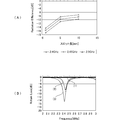
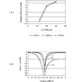
- FIG. 9A shows the antenna efficiency with respect to the full width dimension L of the slot in the applicable frequency band
- FIG. 9B shows the frequency characteristics of the return loss.
- the relationship between the characteristics in FIG. 9B and the dimensions of the slot 11 is as follows when represented by the symbols shown in FIG.
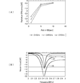
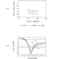
- FIG. 10A shows the antenna efficiency with respect to the antenna size
- FIG. 10B shows the frequency characteristics of the return loss with respect to the antenna size.
- the relationship between the characteristics in FIG. 10B and the dimensions of the slot 11 is as follows when represented by the symbols shown in FIG.
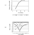
- FIG. 12A shows the antenna efficiency with respect to the interval between the slot 11 and the antenna 20, and FIG. 12B shows the frequency characteristics of the return loss with respect to the interval.
- the horizontal axis of FIG. 12A is 0 when the slot 11 is at the center height of the metal cavity, and the direction in which the slot 11 is lowered from the center is plus, and the direction in which the slot 11 is raised is minus.
- the relationship between each characteristic in FIG. 12B and the height H of the slot 11 is as follows.
- the antenna efficiency becomes maximum when the height H of the slot 11 is at the center height of the metal cavity.
- the return loss characteristic is the best.
- FIG. 14A shows the antenna efficiency with respect to the width dimension CW (see FIG. 1) of the metal cavity
- FIG. 14B shows the frequency characteristics of the return loss with respect to the dimension CW.
- the relationship between each characteristic in FIG. 14B and the width dimension CW of the metal cavity is as follows.
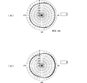
- FIG. 17A is a diagram showing the directivity viewed from directly above the antenna device that has obtained the characteristics of (2) of FIG.
- FIG. 17B is a diagram showing the directivity seen from directly above the antenna device that has obtained the characteristic of (3) of FIG.
- the normal direction (front) of the slot forming surface of the metal cavity corresponds to 90 °. It can be seen that both radiate strongly toward the slot 11 formation side.
Landscapes
- Engineering & Computer Science (AREA)
- Computer Networks & Wireless Communication (AREA)
- Waveguide Aerials (AREA)
- Details Of Aerials (AREA)
- Support Of Aerials (AREA)
Abstract
Description
(1)金属キャビティと、この金属キャビティの内部に配置されたアンテナとを備え、
前記金属キャビティは、一部に絶縁体または誘電体のスロットを備え、
前記スロットの間隙方向は前記アンテナの主偏波の面に直交または非平行の方向であり、
前記アンテナは前記スロットを励振することを特徴とする。
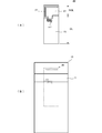
図1は本発明の実施の形態であるアンテナ装置100の斜視図である。このアンテナ装置100は、金属キャビティ10と、この金属キャビティ10の内部に配置されたアンテナ20とを備えている。金属キャビティ10は一部に絶縁体または誘電体のスロット11を備えている。アンテナ20はスロット11を励振する位置に配置されている。
図4は、スロット11の大きさと、給電回路から見たアンテナ装置のリターンロス特性である。スロット11の寸法を図1に示した記号で表すと、条件は次のとおりである。
(2)D=8.5mm,W=25mm,T=5mm
(3)D=8.5mm,W=25mm,T=10mm
(4)D=8.5mm,W=25mm,T=20mm
金属キャビティ10の各部の寸法は、図1に示した記号で表すと、CD=100mm、CH=50mm、CW=25mmである。また、金属キャビティ10の壁厚は1mmである。この条件は以降に示す各種寸法をパラメータにした場合について共通である。
(2)-0.73dB
(3)-0.55dB
(4)-0.66dB
このように、スロット11の間隙Tが大きくなるにつれて広帯域に亘って放射することがわかる。しかし、Tを大きくしすぎるとリターンロスが全体に大きくなる。これはスロット11からの電磁波の放射効率が低下するからであると考えられる。したがって、スロット11が放射効率の良好なスロットアンテナとして作用するように、スロット11の間隙Tを定める。
次に、スロット11の幅Wが、金属キャビティ10のスロット形成面のエッジにまで達していない状態で、スロット11の間隙(高さ)寸法Tを変化させたときのアンテナ効率およびリターンロスの変化について示す。
(2)W=10mm,T=30mm
(3)W=10mm,T=45mm
このように、スロット11の幅Wが小さいままであると、スロット11の間隙(高さ)Tを大きくしてもアンテナ効率はせいぜい-10dBであり、あまり大きくはならないことがわかる。
次に、スロット11の高さTを大きくしたまま、スロット11の幅Wが金属キャビティ10のスロット形成面のエッジにまで達しない範囲で、スロット11の幅Wを変化させたときのアンテナ効率およびリターンロスの変化について示す。
(2)W=5mm,T=45mm
(3)W=10mm,T=45mm
このように、スロット11の幅Wが小さいままであると、アンテナ効率はせいぜい-10dBであり、あまり大きくはならないことがわかる。
次に、スロット11の高さTを修正して、スロット11の幅Wを変化させたときのアンテナ効率とリターンロスなどの特性変化について示す。
(2)L=30mm,T=10mm
(3)L=45mm,T=10mm
(4)L=60mm,T=10mm
なお、金属キャビティの幅(図1に示した寸法CW)は25mmであるので、L=15mmの場合は、スロット11は金属キャビティの側面に達していない。
次に、スロット11の全幅方向寸法Lを最適にしたまま、スロット11の高さTを変化させたときのアンテナ効率およびリターンロスの変化について示す。
(2)L=45mm,T=5mm
(3)L=45mm,T=10mm
図9(B)に表れているように、スロット11の間隙(高さ)Tを小さくするほどアンテナのQ値が高くなり、リターンロスも増大することがわかる。このことからも、スロット11が放射素子として作用していることがわかる。
次に、アンテナのサイズを変化させたときのアンテナ効率およびリターンロスの変化について示す。
(2)GL=15mm,NGL=5mm
(3)GL=25mm,NGL=5mm
なお、スロット11に対するアンテナ素子22の位置関係は一定である。すなわち、グランド導体23の長さを変えることによってアンテナサイズを変更している。
次に、スロット11と金属キャビティ内部のアンテナとの間隔を変化させたときのアンテナ効率およびリターンロスの変化について示す。
(2)d=5mm
(3)d=10mm
スロット11の寸法は、図1に示した記号で表すと、L(=W+2*D)=45mm,T=10mmである。
次に、金属キャビティ10におけるスロット11の位置を変化させたときのアンテナ効率およびリターンロスの変化について示す。
(2)H=0mm
(3)H=+10mm
なお、アンテナ20の位置は固定している。
次に、金属キャビティ10の奥行き寸法CDを変化させたときのアンテナ効率およびリターンロスの変化について示す。
(2)CD=75mm
(3)CD=100mm
図13(A)、図13(B)から明らかなように、金属キャビティの奥行き寸法CDの変化に対するアンテナ特性の変化は小さい。すなわち、金属キャビティの奥行き寸法CDはスロットアンテナとしての特性に影響が無く、アンテナの特性に寄与しているのはやはりスロット11およびアンテナ20の配置領域であることがわかる。
次に、金属キャビティ10の幅寸法CWを変化させたときのアンテナ効率およびリターンロスの変化について示す。
(2)CW=25mm
(3)CW=35mm
図14(A)、図14(B)から明らかなように、金属キャビティの幅寸法CWが小さいほどアンテナ特性は向上する。これは金属キャビティの幅寸法CWが小さいほど、スロットの切り込みが相対的に深くなるためであると考えられる。
次に、金属キャビティ10の高さ寸法CHを変化させたときのアンテナ効率およびリターンロスの変化について示す。
(2)CH=50mm
(3)CH=60mm
図15(A)から明らかなように、金属キャビティの高さ寸法CHが大きいほどアンテナ効率は高い。また、図15(B)から明らかなように、金属キャビティの高さ寸法CHが大きいほど広帯域化することがわかる。
次に、スロット11の誘電率を変化させたときのアンテナ効率およびリターンロスの変化について示す。
(2)εr=20
(3)εr=40
(4)εr=60
図16(A)、図16(B)から明らかなように、スロット11の誘電率が所定の誘電率(この例ではεr=40)のときアンテナ特性は最も向上する。これはスロット11に共振周波数特性があって、適用周波数がその共振周波数に一致するからであるものと考えられる。したがって、スロット11の寸法に応じてアンテナ装置の適用周波数で共振するようにスロット11の誘電率を定めればよい。
図17(A)は図8の(2)の特性を得たアンテナ装置の真上から見た指向性を示す図である。図17(B)は図16の(3)の特性を得たアンテナ装置の真上から見た指向性を示す図である。ここで、金属キャビティのスロット形成面の法線方向(前方)が90°に相当する。
いずれもスロット11の形成側に強く放射することがわかる。
10…金属キャビティ
11…スロット
20…アンテナ
21…基板
22…アンテナ素子
23…グランド導体
100…アンテナ装置
Claims (4)
- 金属キャビティと、この金属キャビティの内部に配置されたアンテナとを備え、
前記金属キャビティは、一部に絶縁体または誘電体のスロットを備え、
前記スロットの間隙方向は前記アンテナの主偏波の面に直交または非平行の方向であり、
前記アンテナは前記スロットを励振することを特徴とするアンテナ装置。 - 前記スロットは空気より誘電率の高い誘電体である、請求項1に記載のアンテナ装置。
- 前記アンテナと前記スロットとの間隔は、適用周波数帯での(1/10)波長以下である、請求項1または2に記載のアンテナ装置。
- 前記スロットが形成された前記金属キャビティの面を、この面の法線方向に見た状態で、前記スロットが前記アンテナの一部に重なっている、請求項1~3のいずれかに記載のアンテナ装置。
Priority Applications (2)
| Application Number | Priority Date | Filing Date | Title |
|---|---|---|---|
| CN201290000385.6U CN203466286U (zh) | 2011-05-23 | 2012-05-10 | 天线装置 |
| JP2013516287A JPWO2012160982A1 (ja) | 2011-05-23 | 2012-05-10 | アンテナ装置 |
Applications Claiming Priority (2)
| Application Number | Priority Date | Filing Date | Title |
|---|---|---|---|
| JP2011-114523 | 2011-05-23 | ||
| JP2011114523 | 2011-05-23 |
Publications (1)
| Publication Number | Publication Date |
|---|---|
| WO2012160982A1 true WO2012160982A1 (ja) | 2012-11-29 |
Family
ID=47217062
Family Applications (1)
| Application Number | Title | Priority Date | Filing Date |
|---|---|---|---|
| PCT/JP2012/061962 Ceased WO2012160982A1 (ja) | 2011-05-23 | 2012-05-10 | アンテナ装置 |
Country Status (3)
| Country | Link |
|---|---|
| JP (1) | JPWO2012160982A1 (ja) |
| CN (1) | CN203466286U (ja) |
| WO (1) | WO2012160982A1 (ja) |
Cited By (8)
| Publication number | Priority date | Publication date | Assignee | Title |
|---|---|---|---|---|
| JP2017098872A (ja) * | 2015-11-27 | 2017-06-01 | Necプラットフォームズ株式会社 | アンテナ装置、無線通信装置およびアンテナ形成方法 |
| JP2017152951A (ja) * | 2016-02-25 | 2017-08-31 | 株式会社リコー | 無線装置、及び情報処理システム |
| WO2017162965A1 (fr) * | 2016-03-22 | 2017-09-28 | Continental Automotive France | Dispositif d'antenne multi-bande intégré à un boîtier tel qu'un système multimédia de véhicule |
| CN107889055A (zh) * | 2017-12-12 | 2018-04-06 | 株洲新科力科技有限公司 | 一种基于无线ap的室内定位导航系统装置 |
| CN107920332A (zh) * | 2017-12-12 | 2018-04-17 | 株洲新科力科技有限公司 | 一种基于无线ap的室内定位导航方法 |
| JP2018137152A (ja) * | 2017-02-22 | 2018-08-30 | パナソニックIpマネジメント株式会社 | 点灯装置及び照明装置 |
| JP2020141422A (ja) * | 2020-05-25 | 2020-09-03 | 株式会社リコー | 無線装置 |
| JP2022023043A (ja) * | 2017-02-22 | 2022-02-07 | パナソニックIpマネジメント株式会社 | 照明装置 |
Families Citing this family (4)
| Publication number | Priority date | Publication date | Assignee | Title |
|---|---|---|---|---|
| CN105530784B (zh) * | 2014-12-26 | 2016-10-12 | 比亚迪股份有限公司 | 一种通讯设备金属外壳 |
| CN105322275A (zh) * | 2015-12-03 | 2016-02-10 | 深圳市信维通信股份有限公司 | 背腔缝隙天线结构及电子设备 |
| CN106129609B (zh) * | 2016-07-25 | 2018-08-28 | 清华大学 | 双极化全向低风阻马刀形天线 |
| CN116365243A (zh) * | 2021-10-15 | 2023-06-30 | 荣耀终端有限公司 | 谐振腔天线及电子设备 |
Citations (2)
| Publication number | Priority date | Publication date | Assignee | Title |
|---|---|---|---|---|
| JP2002064320A (ja) * | 2000-08-21 | 2002-02-28 | Furukawa Electric Co Ltd:The | 無線端末 |
| JP2004304463A (ja) * | 2003-03-31 | 2004-10-28 | Shimizu Corp | Phs位置情報利用システム |
-
2012
- 2012-05-10 CN CN201290000385.6U patent/CN203466286U/zh not_active Expired - Lifetime
- 2012-05-10 JP JP2013516287A patent/JPWO2012160982A1/ja active Pending
- 2012-05-10 WO PCT/JP2012/061962 patent/WO2012160982A1/ja not_active Ceased
Patent Citations (2)
| Publication number | Priority date | Publication date | Assignee | Title |
|---|---|---|---|---|
| JP2002064320A (ja) * | 2000-08-21 | 2002-02-28 | Furukawa Electric Co Ltd:The | 無線端末 |
| JP2004304463A (ja) * | 2003-03-31 | 2004-10-28 | Shimizu Corp | Phs位置情報利用システム |
Cited By (14)
| Publication number | Priority date | Publication date | Assignee | Title |
|---|---|---|---|---|
| JP2017098872A (ja) * | 2015-11-27 | 2017-06-01 | Necプラットフォームズ株式会社 | アンテナ装置、無線通信装置およびアンテナ形成方法 |
| JP2017152951A (ja) * | 2016-02-25 | 2017-08-31 | 株式会社リコー | 無線装置、及び情報処理システム |
| US10587036B2 (en) | 2016-03-22 | 2020-03-10 | Continental Automotive France | Multiband antenna device integrated with a housing such as a vehicle multimedia system |
| FR3049396A1 (fr) * | 2016-03-22 | 2017-09-29 | Continental Automotive France | Dispositif d'antenne multi-bande integre a un boitier tel qu'un systeme multimedia de vehicule |
| CN108886195A (zh) * | 2016-03-22 | 2018-11-23 | 法国大陆汽车公司 | 集成到诸如车辆多媒体系统之类的箱体的多带天线设备 |
| US20190341681A1 (en) * | 2016-03-22 | 2019-11-07 | Continental Automotive France | Multiband antenna device integrated with a housing such as a vehicle multimedia system |
| WO2017162965A1 (fr) * | 2016-03-22 | 2017-09-28 | Continental Automotive France | Dispositif d'antenne multi-bande intégré à un boîtier tel qu'un système multimédia de véhicule |
| JP2018137152A (ja) * | 2017-02-22 | 2018-08-30 | パナソニックIpマネジメント株式会社 | 点灯装置及び照明装置 |
| JP2022023043A (ja) * | 2017-02-22 | 2022-02-07 | パナソニックIpマネジメント株式会社 | 照明装置 |
| JP7157964B2 (ja) | 2017-02-22 | 2022-10-21 | パナソニックIpマネジメント株式会社 | 照明装置 |
| CN107889055A (zh) * | 2017-12-12 | 2018-04-06 | 株洲新科力科技有限公司 | 一种基于无线ap的室内定位导航系统装置 |
| CN107920332A (zh) * | 2017-12-12 | 2018-04-17 | 株洲新科力科技有限公司 | 一种基于无线ap的室内定位导航方法 |
| JP2020141422A (ja) * | 2020-05-25 | 2020-09-03 | 株式会社リコー | 無線装置 |
| JP6992842B2 (ja) | 2020-05-25 | 2022-01-13 | 株式会社リコー | 無線装置 |
Also Published As
| Publication number | Publication date |
|---|---|
| CN203466286U (zh) | 2014-03-05 |
| JPWO2012160982A1 (ja) | 2014-07-31 |
Similar Documents
| Publication | Publication Date | Title |
|---|---|---|
| WO2012160982A1 (ja) | アンテナ装置 | |
| US8836581B2 (en) | Antenna having internal and external structures | |
| US9698487B2 (en) | Array antenna | |
| JP6528748B2 (ja) | アンテナ装置 | |
| KR101306547B1 (ko) | 평면형 역 에프 안테나용 방사체 및 이를 이용한 안테나 | |
| EP2073308B1 (en) | Antenna device | |
| Ghosh et al. | Miniaturization of slot antennas using wire loading | |
| JP5449036B2 (ja) | アンテナおよびアンテナ装置 | |
| JP2001339226A (ja) | アンテナ装置 | |
| JP2006174365A (ja) | アンテナ装置 | |
| JP2016146558A (ja) | アンテナ及びそれを用いた通信装置 | |
| JP4690834B2 (ja) | 多周波共用アンテナ | |
| JP4323413B2 (ja) | パッチアンテナ、アレイアンテナおよびそれを備えた実装基板 | |
| US20110109510A1 (en) | Antenna | |
| JPH11274845A (ja) | アンテナ装置 | |
| JP5078732B2 (ja) | アンテナ装置 | |
| CN105655699B (zh) | 一种采用基片集成波导的背腔缝隙圆极化天线 | |
| JP6004180B2 (ja) | アンテナ装置 | |
| JP2011130280A (ja) | アンテナ及び無線通信方法 | |
| CN102379065A (zh) | 天线装置 | |
| JP3454151B2 (ja) | アンテナ装置 | |
| JP2004328067A (ja) | 平面アンテナ | |
| US20110254737A1 (en) | Slotted antenna device | |
| JP5858844B2 (ja) | アンテナ装置 | |
| JP2011229072A (ja) | アンテナ装置 |
Legal Events
| Date | Code | Title | Description |
|---|---|---|---|
| WWE | Wipo information: entry into national phase |
Ref document number: 201290000385.6 Country of ref document: CN |
|
| 121 | Ep: the epo has been informed by wipo that ep was designated in this application |
Ref document number: 12789763 Country of ref document: EP Kind code of ref document: A1 |
|
| ENP | Entry into the national phase |
Ref document number: 2013516287 Country of ref document: JP Kind code of ref document: A |
|
| NENP | Non-entry into the national phase |
Ref country code: DE |
|
| 122 | Ep: pct application non-entry in european phase |
Ref document number: 12789763 Country of ref document: EP Kind code of ref document: A1 |