WO2012160896A1 - 空気入りタイヤ - Google Patents
空気入りタイヤ Download PDFInfo
- Publication number
- WO2012160896A1 WO2012160896A1 PCT/JP2012/059888 JP2012059888W WO2012160896A1 WO 2012160896 A1 WO2012160896 A1 WO 2012160896A1 JP 2012059888 W JP2012059888 W JP 2012059888W WO 2012160896 A1 WO2012160896 A1 WO 2012160896A1
- Authority
- WO
- WIPO (PCT)
- Prior art keywords
- tire
- fastener
- electronic circuit
- circuit device
- fasteners
- Prior art date
- Legal status (The legal status is an assumption and is not a legal conclusion. Google has not performed a legal analysis and makes no representation as to the accuracy of the status listed.)
- Ceased
Links
Images


Classifications
-
- B—PERFORMING OPERATIONS; TRANSPORTING
- B60—VEHICLES IN GENERAL
- B60C—VEHICLE TYRES; TYRE INFLATION; TYRE CHANGING; CONNECTING VALVES TO INFLATABLE ELASTIC BODIES IN GENERAL; DEVICES OR ARRANGEMENTS RELATED TO TYRES
- B60C23/00—Devices for measuring, signalling, controlling, or distributing tyre pressure or temperature, specially adapted for mounting on vehicles; Arrangement of tyre inflating devices on vehicles, e.g. of pumps or of tanks; Tyre cooling arrangements
-
- B—PERFORMING OPERATIONS; TRANSPORTING
- B29—WORKING OF PLASTICS; WORKING OF SUBSTANCES IN A PLASTIC STATE IN GENERAL
- B29D—PRODUCING PARTICULAR ARTICLES FROM PLASTICS OR FROM SUBSTANCES IN A PLASTIC STATE
- B29D30/00—Producing pneumatic or solid tyres or parts thereof
- B29D30/0061—Accessories, details or auxiliary operations not otherwise provided for
-
- B—PERFORMING OPERATIONS; TRANSPORTING
- B60—VEHICLES IN GENERAL
- B60C—VEHICLE TYRES; TYRE INFLATION; TYRE CHANGING; CONNECTING VALVES TO INFLATABLE ELASTIC BODIES IN GENERAL; DEVICES OR ARRANGEMENTS RELATED TO TYRES
- B60C23/00—Devices for measuring, signalling, controlling, or distributing tyre pressure or temperature, specially adapted for mounting on vehicles; Arrangement of tyre inflating devices on vehicles, e.g. of pumps or of tanks; Tyre cooling arrangements
- B60C23/02—Signalling devices actuated by tyre pressure
- B60C23/04—Signalling devices actuated by tyre pressure mounted on the wheel or tyre
- B60C23/0491—Constructional details of means for attaching the control device
- B60C23/0493—Constructional details of means for attaching the control device for attachment on the tyre
-
- B—PERFORMING OPERATIONS; TRANSPORTING
- B29—WORKING OF PLASTICS; WORKING OF SUBSTANCES IN A PLASTIC STATE IN GENERAL
- B29D—PRODUCING PARTICULAR ARTICLES FROM PLASTICS OR FROM SUBSTANCES IN A PLASTIC STATE
- B29D30/00—Producing pneumatic or solid tyres or parts thereof
- B29D30/0061—Accessories, details or auxiliary operations not otherwise provided for
- B29D2030/0072—Attaching fasteners to tyres, e.g. patches, in order to connect devices to tyres
-
- B—PERFORMING OPERATIONS; TRANSPORTING
- B29—WORKING OF PLASTICS; WORKING OF SUBSTANCES IN A PLASTIC STATE IN GENERAL
- B29D—PRODUCING PARTICULAR ARTICLES FROM PLASTICS OR FROM SUBSTANCES IN A PLASTIC STATE
- B29D30/00—Producing pneumatic or solid tyres or parts thereof
- B29D30/0061—Accessories, details or auxiliary operations not otherwise provided for
- B29D2030/0077—Directly attaching monitoring devices to tyres before or after vulcanization, e.g. microchips
-
- F—MECHANICAL ENGINEERING; LIGHTING; HEATING; WEAPONS; BLASTING
- F16—ENGINEERING ELEMENTS AND UNITS; GENERAL MEASURES FOR PRODUCING AND MAINTAINING EFFECTIVE FUNCTIONING OF MACHINES OR INSTALLATIONS; THERMAL INSULATION IN GENERAL
- F16B—DEVICES FOR FASTENING OR SECURING CONSTRUCTIONAL ELEMENTS OR MACHINE PARTS TOGETHER, e.g. NAILS, BOLTS, CIRCLIPS, CLAMPS, CLIPS OR WEDGES; JOINTS OR JOINTING
- F16B21/00—Means for preventing relative axial movement of a pin, spigot, shaft or the like and a member surrounding it; Stud-and-socket releasable fastenings
- F16B21/06—Releasable fastening devices with snap-action
- F16B21/08—Releasable fastening devices with snap-action in which the stud, pin, or spigot has a resilient part
-
- Y—GENERAL TAGGING OF NEW TECHNOLOGICAL DEVELOPMENTS; GENERAL TAGGING OF CROSS-SECTIONAL TECHNOLOGIES SPANNING OVER SEVERAL SECTIONS OF THE IPC; TECHNICAL SUBJECTS COVERED BY FORMER USPC CROSS-REFERENCE ART COLLECTIONS [XRACs] AND DIGESTS
- Y10—TECHNICAL SUBJECTS COVERED BY FORMER USPC
- Y10T—TECHNICAL SUBJECTS COVERED BY FORMER US CLASSIFICATION
- Y10T24/00—Buckles, buttons, clasps, etc.
- Y10T24/45—Separable-fastener or required component thereof [e.g., projection and cavity to complete interlock]
Definitions
- the present invention relates to a pneumatic tire, and more particularly to a pneumatic tire in which an electronic circuit device is attached to the inner surface of the pneumatic tire by a novel method.
- Patent Document 1 a mounting method of attaching a tire tag (high frequency identification tag) or a chip using a so-called hook-and-loop fastener such as a hook-and-loop fastener or a hook-and-hook fastener to an inner liner of a raw tire has been proposed (Patent Document 1).
- a pneumatic tire in which a surface fastener is vulcanized and bonded to a region corresponding to a tread portion on the tire inner surface, and a sound absorbing material is attached to the tire inner surface via the surface fastener (Patent Document 2). ).
- the mounting method using the hook-and-loop fastener proposed in Patent Documents 1 and 2 realizes a relatively strong engaging force during mounting, and there is a problem of some positional deviation during mounting work. This is preferable in that the engagement in a planar shape can be realized without using a non-symmetrical structure.
- the individual engagement elements of the hook-and-loop fastener are caused by the fact that the inner peripheral surface of the pneumatic tire is a curved curved surface.
- the engagement state is not ideal, and a part of the engagement portion floats at the end portion, the center portion, and the like, and the magnitude of the obtained engagement force varies (positional variation within the tire. Variation may occur, and the engagement force as expected may not be obtained.
- surface fasteners caused by the occurrence of partial physical deterioration and its progress by repeated deformation and compression due to rolling at high speed under relatively high temperature conditions for a long time. In some cases, the entire engagement force deteriorates or decreases over time, and it is difficult to maintain the desired engagement force over a long period of time.
- the inventors of the present invention first have a particularly large engagement force and a variation in the magnitude (positional variation within the tire, variation between tires). There is almost no deterioration and decrease over time in the engagement force due to severe use conditions in which deformation and compression accompanying tire rolling at relatively high temperature and high speed are repeated for a long time.
- a pneumatic tire using a method of attaching an object capable of maintaining a desired engagement force a pneumatic tire having one of a pair of mechanical fasteners that can be separated into two on the tire inner surface has been proposed ( Japanese Patent Application No. 2010-167839).
- the mechanical fastener is a pair of fasteners that can be separated into two fasteners and can be physically engaged again, and this engagement and separation can be freely repeated. It is composed of ingredients.
- Typical examples are mechanical fasteners called hooks or snaps, which are generally used in the clothing industry, and more specifically, snap buttons, ring snaps, ring hooks, American snaps, American hooks, eyelet hooks, spring hooks.
- the so-called “surface fastener” in which the area of the engaging portion is infinite in all areas, and the engaging portion has a small area (for example, preferably about 1 to 115 mm 2). Etc., more preferably about 4 to 90 mm 2 ). That is, for example, even a small area of about 1 to 115 mm 2 or the like can be engaged by a mechanical male / female structure or the like, and can be of a known structure.
- the material is made of metal, rubber, synthetic resin or the like. This method using the mechanical fastener is excellent in terms of the magnitude of the engagement force to be obtained, the variation in the magnitude, the certainty of the engagement work, and the like.
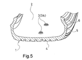
- FIG. 5 shows a state in which one of the mechanical fasteners is attached to the tire inner peripheral surface.
- one fastener 3 (3 ⁇ / b> A) of a pair of mechanical fasteners that can be separated into two fasteners is disposed on the tire inner surface 2 of the pneumatic tire 1.
- 4 is a tread portion
- 5 is a sidewall portion
- 6 is a bead portion.
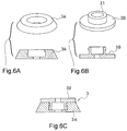
- the mechanical fastener 3 is composed of a pair of fasteners of a concave or female fastener 3A as shown in FIG. 6A and a convex or male fastener 3B as shown in FIG. 6B.
- the engaged state is shown in FIG. 6C.
- the object of the present invention is to provide a liquid such as a puncture repair liquid when a puncture is applied to a tire having an electronic circuit device attached to the tire inner surface.
- An object of the present invention is to provide a pneumatic tire in which there is no possibility that the electronic circuit device will be broken by being attached to an electronic circuit device such as a pneumatic sensor.
- the pneumatic tire of the present invention that achieves the above-described object has the following configuration (1).
- (1) It has one fastener of a pair of mechanical fasteners that can be separated into two within a range from the tip of the bead portion of the tire inner surface to the maximum width position of the tire, and the one fastener
- the pneumatic tire of the present invention preferably has any one of the following configurations (2) to (7).
- the main body portion of the electronic circuit device is housed in a housing, and an interval between the tire inner surface and the housing excluding a fitting portion between the fastener on the housing side and the fastener on the tire inner surface side is set.
- a mechanism for preventing the electronic circuit device from rotating by sliding both fasteners at the fitting portion where the two fasteners are fitted is provided in the vicinity of the fitting portion.
- the one fastener is provided at equal intervals in two or more locations in the tire circumferential direction in the region in the range from the tip of the bead portion of the tire inner surface to the maximum width position of the tire.
- the liquid such as puncture repair liquid is injected into the tire when punctured
- the liquid is a pneumatic sensor or the like.
- the electronic circuit device is not likely to be broken by being attached to the electronic circuit device.
- a pneumatic tire can be provided in which the effect of the configuration of (1) described above can be obtained more reliably and with a high effect.
- the effect of the configuration of (1) described above is obtained, and it is excellent in that the mounting position of the electronic circuit device can be set to an optimum position in relation to other members such as an air valve.
- a pneumatic tire is provided.
- the pneumatic circuit is provided as an electronic circuit device, and the effect obtained by the configuration of (1) described above can be further enhanced, and the tire is more accurately and highly durable.
- a pneumatic tire capable of detecting the air pressure inside is provided.
- FIG. 1A is a schematic cross-sectional view in the tire meridian direction showing an embodiment of the pneumatic tire of the present invention
- FIG. 1B is an ellipse centered on the mounting portion of the electronic circuit device 9 on the diagram of FIG. 1A. It is the principal part expanded sectional view which expanded and showed the vicinity.
- FIG. 2A and FIG. Some fasteners are shown, and FIG. 2C shows their engaged state.
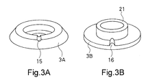
- 3A and 3B illustrate another example of a fastener having a mechanism for preventing the electronic circuit device from rotating among a pair of mechanical fasteners used in the pneumatic tire of the present invention.
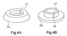
- 4A and 4B show still another example of a fastener having a mechanism for preventing the electronic circuit device from rotating among a pair of mechanical fasteners used in the pneumatic tire of the present invention.
- FIG. 6A and FIG. 6B show a pair of fasteners 3A and 3B, and FIG. 6C shows a state in which they are engaged.
- FIGS. 6A and 6B what is drawn upward is a perspective view seen from above, and what is drawn below is a cross-sectional view seen from the front.
- the pneumatic tire according to the embodiment of the present invention is separated into two in a region Z in the range from the bead portion tip 7 of the tire inner surface to the maximum width position 8 of the tire.
- An electronic circuit device 9 having one fastener 3A of a pair of possible mechanical fasteners 3 and having the other fastener 3B engaged with the one fastener is connected to the two fasteners 3A, 3B.
- the tire is fixed to the tire inner surface 2 by fitting.
- the positioning of the electronic circuit device can be accurately performed because it is uniquely determined by the position of the fastener 3A provided on the tire inner surface 2.
- the decrease in engagement force due to this is small or hardly reduced, and stable mounting is always achieved at an accurate position.
- the intended function of the electronic circuit device can be exhibited accurately and with good durability.
- the installation position can be accurately set as desired without making a mistake due to the wrong type. This is very effective in that it can be installed accurately without making a mistake even when the electronic circuit device such as a sensor attached for each type of tire is different.
- the main body (not shown) of the electronic circuit device 9 is housed in the housing 12, and the fastener 3B on the housing 12 side is engaged with the fastener 3A on the tire inner surface side. It is preferable that the electronic circuit device 9 is fixed by the engagement of both the fasteners 3A and 3B so that the distance L between the tire inner surface 2 excluding the portion and the housing 12 is 2 to 40 mm.
- the liquid does not adhere to the electronic circuit device, and the expected function of the electronic circuit device 9 is more accurately and durable. It can be demonstrated well.
- the distance L can be obtained as desired by changing the shapes and dimensions of the fasteners 3A and 3B and changing the shape and dimensions of the electronic circuit device 9.
- a more preferable range of L is 3 to 20 mm.
- a mechanism for preventing the electronic circuit device 3 from rotating due to the two fasteners 3A, 3B sliding at the fitting portion where the two fasteners 3A, 3B are fitted is provided in the vicinity of the fitting portion. It is preferable that This is because by preventing the electronic circuit device 9 from rotating, the transmission quality of radio waves can be stabilized and improved when the electronic circuit device 9 has a wireless transmission function.
- the cross-sectional shape of the engagement tube portion 21 is elliptical or polygonal.
- a non-circular cross section such as a shape can be used so as not to slide and rotate.
- FIG. 2 shows an example in which the concave portion 13 is provided in the concave or female fastener 3A and the convex portion 14 is provided in the convex or male fastener 3B.
- the fasteners 3A and 3B cannot be engaged, and the concave portion 13 and the convex portion 14 are fitted.
- the fasteners 3A and 3B cannot rotate relative to each other.
- the recessed part 13 and the convex part 14 do not need to be provided in the main body of fastener 3A, 3B, and this recessed part 13 and the convex part 14 may be provided in a base part.
- FIG. 3 and FIG. 4 show other examples of mechanisms for preventing further rotation, respectively.
- the horizontal groove 15 and the horizontal ridge 16 as shown in FIG.
- the pair of fasteners 3A and 3B is provided, or an example in which the vertical groove 17 and the vertical protrusion 18 are provided in the pair of fasteners 3A and 3B as shown in FIG.
- an identification mark is provided on the inner surface of the tire corresponding to the position where one fastener 3A is provided, and the position can be visually confirmed on the outer side of the tire.
- the air valve for filling the puncture repair liquid and the position where the electronic circuit device is installed are shifted in the tire circumferential direction. This is because it is effective and preferable so that an operator or the like can visually confirm such a positional relationship from the outside of the tire.
- the amount of shift is preferably a shift of 45 ° or more in the circumferential phase angle with the tire rotation center as the center point, and the position where the electronic circuit device is installed outside the tire can be visually confirmed.
- one fastener 3A is provided at equal intervals in two or more locations in the tire circumferential direction in a region Z in a range from the tip of the bead portion on the tire inner surface to the maximum width position of the tire.
- the tire is usually assembled with the light spot mark and the installation position of the air valve so that the optimal mounting position of the fastener 3A can be selected. Because it becomes like this.
- it is preferable to provide them at equal intervals in the tire circumferential direction so as not to deteriorate the mass balance of the tire. If it is provided at three positions at 180 ° facing positions, it is preferably installed at positions separated by approximately 120 °.
- the fastener 3A may be installed on the bead portions on both sides of the tire center. Since air valves are often installed at a position offset to one side in the width direction of the wheel, when assembling a tire and a wheel, the electronic circuit device can be selected to be installed on the side without the air valve. It is.
- one or more fasteners 3A may be provided in two or more locations in the tire radial direction within a region Z in a range from the tip of the bead portion on the tire inner surface to the maximum width position of the tire. This is so that the electronic circuit device can be selected to be installed at a more suitable position in the tire radial direction.
- the electronic circuit device is a pneumatic sensor. This is because the air pressure sensor requires an air hole when stored in the housing, so that the effect of the present invention for preventing the inflow of liquid into the housing and the submersion of the electronic circuit device is most noticeable.
- the air pressure sensor when the electronic circuit device is an air pressure sensor, the air pressure sensor is housed in the housing, and the housing has an air hole on the surface opposite to the surface having the fastener 3B. It is preferable that it is comprised. By constructing the air hole on the surface opposite to the surface having the fastener 3B, it is possible to more effectively prevent the liquid from entering the air hole and to obtain the effect of the present invention higher. Because it can.
- the “maximum width position of the tire” as used in the present invention means that a pneumatic tire is mounted on an applicable rim prescribed in JATMA YEAR BOOK 2010 (Japan Automobile Tire Association Standard), and the air pressure is filled to 220 kPa to provide no load.
Landscapes
- Engineering & Computer Science (AREA)
- Mechanical Engineering (AREA)
- General Engineering & Computer Science (AREA)
- Measuring Fluid Pressure (AREA)
- Tires In General (AREA)
Abstract
Description
(1)タイヤ内面のビード部先端からタイヤの最大幅位置までの範囲の領域内に2つに分離できる一対の機械的留め具のうちの一方の留め具を有し、該一方の留め具に係合する他方の留め具を有する電子回路装置を、前記2つの留め具を嵌合させることによってタイヤ内面に固定したことを特徴とする空気入りタイヤ。
(2)前記電子回路装置の本体部が、筐体内に収納されており、該筐体側の前記留め具とタイヤ内面側の留め具との嵌合部分を除くタイヤ内面と筐体との間隔が2~40mmとなるようにして該電子回路装置が固定されていることを特徴とする上記(1)の空気入りタイヤ。
(3)前記2つの留め具が嵌合された嵌合部で両留め具が摺動して前記電子回路装置が回転することを防止する機構が、該嵌合部の近傍に設けられていることを特徴とする上記(1)または(2)の空気入りタイヤ。
(4)タイヤ内面において前記一方の留め具が設けられている位置に対応し、タイヤ外側にその位置を目視で確認可能な識別マークが付されていることを特徴とする上記(1)~(3)のいずれかの空気入りタイヤ。
(5)タイヤ内面のビード部先端からタイヤの最大幅位置までの範囲の前記領域内に前記一方の留め具が、タイヤ周方向に2箇所以上、等間隔に設けられていることを特徴とする上記(1)~(4)のいずれかの空気入りタイヤ。
(6)前記電子回路装置が、空気圧センサを有することを特徴とする上記(1)~(5)のいずれかの空気入りタイヤ。
(7)前記空気圧センサが筐体内に収納され、該筐体が、留め具を有する面と反対側の面に通気孔を有することを特徴とする上記(6)の空気入りタイヤ。
本発明の目的、特徴、局面、及び利点は、以下の詳細な説明と添付図面とによって、より明白となる。
2:タイヤ内面
3:機械的留め具
3A:機械的留め具(凹型あるいは雌型の留め具)
3B:機械的留め具(凸型あるいは雄型の留め具)
4:トレッド部
5:サイドウォール部
6:ビード部
7:タイヤ内面のビード部先端
8:タイヤの最大幅位置
9:電子回路装置
10:リム
11:空気バルブ
12:電子回路装置の筐体
13:凹部
14:凸部
15:水平溝
16:水平凸条
17:垂直溝
18:垂直凸条
21:係合筒部
L:タイヤ内面2と筐体との間隔
Z:タイヤ内面2のビード部先端7からタイヤの最大幅位置8までの範囲の領域
Claims (7)
- タイヤ内面のビード部先端からタイヤの最大幅位置までの範囲の領域内に設けられ、2つに分離できる一対の機械的留め具のうちの一方である留め具と、
該一方の留め具に係合する他方の留め具を有する電子回路装置であって、前記2つの留め具を嵌合させることによってタイヤ内面に固定されている電子回路装置と、を備える空気入りタイヤ。 - 前記電子回路装置が、筐体と当該筐体に収納された本体部とを含んでおり、該筐体側の前記留め具と前記タイヤ内面側の留め具との嵌合部分を除く前記タイヤ内面と前記筐体との間隔が2~40mmとなるようにして該電子回路装置が固定されている請求項1記載の空気入りタイヤ。
- 前記2つの留め具が嵌合された嵌合部で両留め具が摺動して前記電子回路装置が回転することを防止する機構が、該嵌合部の近傍に設けられている請求項1または2記載の空気入りタイヤ。
- タイヤ内面において前記一方の留め具が設けられている位置に対応し、タイヤ外側にその位置を目視で確認可能な識別マークが付されている請求項1~3のいずれかに記載の空気入りタイヤ。
- タイヤ内面のビード部先端からタイヤの最大幅位置までの範囲の前記領域内に前記一方の留め具が、タイヤ周方向に2箇所以上、等間隔に設けられている請求項1~4のいずれかに記載の空気入りタイヤ。
- 前記電子回路装置が、空気圧センサを有する請求項1~5のいずれかに記載の空気入りタイヤ。
- 前記空気圧センサが筐体内に収納され、該筐体が、留め具を有する面と反対側の面に通気孔を有する請求項6記載の空気入りタイヤ。
Priority Applications (5)
| Application Number | Priority Date | Filing Date | Title |
|---|---|---|---|
| KR1020137033767A KR101887727B1 (ko) | 2011-05-23 | 2012-04-11 | 공기 주입 타이어 |
| US14/119,081 US9908372B2 (en) | 2011-05-23 | 2012-04-11 | Pneumatic tire |
| DE112012002200.9T DE112012002200T5 (de) | 2011-05-23 | 2012-04-11 | Luftreifen |
| CN201280024625.0A CN103561973B (zh) | 2011-05-23 | 2012-04-11 | 充气轮胎 |
| KR1020187018408A KR101900654B1 (ko) | 2011-05-23 | 2012-04-11 | 공기 주입 타이어 |
Applications Claiming Priority (2)
| Application Number | Priority Date | Filing Date | Title |
|---|---|---|---|
| JP2011114609A JP5626117B2 (ja) | 2011-05-23 | 2011-05-23 | 空気入りタイヤ |
| JP2011-114609 | 2011-05-23 |
Publications (1)
| Publication Number | Publication Date |
|---|---|
| WO2012160896A1 true WO2012160896A1 (ja) | 2012-11-29 |
Family
ID=47216982
Family Applications (1)
| Application Number | Title | Priority Date | Filing Date |
|---|---|---|---|
| PCT/JP2012/059888 Ceased WO2012160896A1 (ja) | 2011-05-23 | 2012-04-11 | 空気入りタイヤ |
Country Status (6)
| Country | Link |
|---|---|
| US (1) | US9908372B2 (ja) |
| JP (1) | JP5626117B2 (ja) |
| KR (2) | KR101900654B1 (ja) |
| CN (1) | CN103561973B (ja) |
| DE (1) | DE112012002200T5 (ja) |
| WO (1) | WO2012160896A1 (ja) |
Cited By (2)
| Publication number | Priority date | Publication date | Assignee | Title |
|---|---|---|---|---|
| US20170259630A1 (en) * | 2014-07-28 | 2017-09-14 | The Yokohama Rubber Co., Ltd. | Pneumatic Tire |
| US10766317B2 (en) | 2013-12-06 | 2020-09-08 | The Yokohama Rubber Co., Ltd. | Pneumatic tire |
Families Citing this family (12)
| Publication number | Priority date | Publication date | Assignee | Title |
|---|---|---|---|---|
| WO2015087879A1 (ja) * | 2013-12-13 | 2015-06-18 | 横浜ゴム株式会社 | 空気入りタイヤ |
| JP6382529B2 (ja) * | 2014-02-27 | 2018-08-29 | 株式会社ブリヂストン | 機能部品取付台座、及び、タイヤ |
| FR3063040B1 (fr) * | 2017-02-17 | 2021-06-18 | Michelin & Cie | Dispositif de fixation a une enveloppe pneumatique d'un organe electronique. |
| JP6594506B1 (ja) * | 2018-10-03 | 2019-10-23 | Toyo Tire株式会社 | タイヤ |
| EP3659458B1 (en) * | 2018-11-30 | 2022-11-23 | Carmo Holding ApS | Metal eyelet |
| KR102218154B1 (ko) | 2020-02-17 | 2021-02-23 | 한국타이어앤테크놀로지 주식회사 | 비교체식 일체형 전자장치의 제조방법 |
| CN112026219B (zh) * | 2020-09-17 | 2025-03-18 | 泰凯英(青岛)专用轮胎技术研究开发有限公司 | 工程轮胎缺气保用装置 |
| KR102405145B1 (ko) * | 2020-09-25 | 2022-06-07 | 금호타이어 주식회사 | 센서장치 부착을 위한 타이어 |
| KR102470850B1 (ko) * | 2020-12-21 | 2022-11-29 | 한국타이어앤테크놀로지 주식회사 | 압전센서를 장착한 비공기압 타이어 및 이의 제조방법 |
| JP2025186594A (ja) * | 2022-11-24 | 2025-12-24 | アルプスアルパイン株式会社 | 取付組立体 |
| JP2024090468A (ja) * | 2022-12-23 | 2024-07-04 | 横浜ゴム株式会社 | タイヤ |
| CN121285463A (zh) | 2023-11-13 | 2026-01-06 | 韩国轮胎与科技株式会社 | 与电子装置一体化的轮胎的制造方法及通过该方法制造的与电子装置一体化的轮胎 |
Citations (14)
| Publication number | Priority date | Publication date | Assignee | Title |
|---|---|---|---|---|
| JPS5266876U (ja) * | 1975-11-12 | 1977-05-18 | ||
| JPS54133268U (ja) * | 1978-03-07 | 1979-09-14 | ||
| JP2002502765A (ja) * | 1998-02-12 | 2002-01-29 | ミシュラン ルシェルシェ エ テクニク ソシエテ アノニム | タイヤ用電子パッケージの取付け手段 |
| JP2004196023A (ja) * | 2002-12-16 | 2004-07-15 | Mitsubishi Electric Corp | タイヤ空気圧検出器 |
| JP2004245622A (ja) * | 2003-02-12 | 2004-09-02 | Pacific Ind Co Ltd | 圧力センサ、送信機、及びタイヤ状態監視装置 |
| JP2005212562A (ja) * | 2004-01-28 | 2005-08-11 | Bridgestone Corp | 内部温度検知機能付きタイヤ及びタイヤ内部温度検知方法 |
| JP2005343281A (ja) * | 2004-06-02 | 2005-12-15 | Bridgestone Corp | タイヤの動的状態推定方法とその装置、及び、センサ付タイヤ |
| JP2006044503A (ja) * | 2004-08-05 | 2006-02-16 | Yokohama Rubber Co Ltd:The | 空気入りタイヤ |
| JP2006056443A (ja) * | 2004-08-23 | 2006-03-02 | Yokohama Rubber Co Ltd:The | 空気入りタイヤ |
| JP2007002907A (ja) * | 2005-06-23 | 2007-01-11 | Nomura Sd:Kk | ベースと支柱の結合構造 |
| JP2007326536A (ja) * | 2006-06-09 | 2007-12-20 | Bridgestone Corp | 電子装置取付構造及び空気入りタイヤ |
| JP2008230411A (ja) * | 2007-03-20 | 2008-10-02 | Bridgestone Corp | 電子装置取付構造及び空気入りタイヤ |
| JP2012025319A (ja) * | 2010-07-27 | 2012-02-09 | Yokohama Rubber Co Ltd:The | 空気入りタイヤおよびその製造方法 |
| JP2012025318A (ja) * | 2010-07-27 | 2012-02-09 | Yokohama Rubber Co Ltd:The | 空気入りタイヤ |
Family Cites Families (8)
| Publication number | Priority date | Publication date | Assignee | Title |
|---|---|---|---|---|
| JPS5266876A (en) | 1975-11-29 | 1977-06-02 | Shin Kobe Electric Machinery | Method of manufacturing electrode for gas dispersion |
| JPS5830076B2 (ja) | 1978-04-06 | 1983-06-27 | 蛇の目ミシン工業株式会社 | ミシン用糸駒の情報信号読取装置 |
| US6217683B1 (en) | 1998-02-12 | 2001-04-17 | Michelin Recherche Et Technique S.A. | Monitored vehicle tire and monitor retainer assembly |
| CA2828019C (en) | 2002-02-18 | 2015-05-19 | Bridgestone Firestone North American Tire, Llc | Attachment method for tire tag |
| EP1798074B1 (en) * | 2004-10-05 | 2012-09-26 | The Yokohama Rubber Co., Ltd. | Pneumatic tire |
| JP4778786B2 (ja) * | 2005-12-12 | 2011-09-21 | 株式会社ブリヂストン | 電子装置取付構造、及び空気入りタイヤ |
| JP5242428B2 (ja) | 2009-01-20 | 2013-07-24 | アイシン精機株式会社 | 姿勢安定化制御装置及び該姿勢安定化制御装置を備えた車両 |
| JP2011114609A (ja) | 2009-11-27 | 2011-06-09 | Kyocera Corp | 携帯電子機器 |
-
2011
- 2011-05-23 JP JP2011114609A patent/JP5626117B2/ja active Active
-
2012
- 2012-04-11 KR KR1020187018408A patent/KR101900654B1/ko not_active Expired - Fee Related
- 2012-04-11 CN CN201280024625.0A patent/CN103561973B/zh active Active
- 2012-04-11 KR KR1020137033767A patent/KR101887727B1/ko not_active Expired - Fee Related
- 2012-04-11 DE DE112012002200.9T patent/DE112012002200T5/de active Pending
- 2012-04-11 WO PCT/JP2012/059888 patent/WO2012160896A1/ja not_active Ceased
- 2012-04-11 US US14/119,081 patent/US9908372B2/en active Active
Patent Citations (14)
| Publication number | Priority date | Publication date | Assignee | Title |
|---|---|---|---|---|
| JPS5266876U (ja) * | 1975-11-12 | 1977-05-18 | ||
| JPS54133268U (ja) * | 1978-03-07 | 1979-09-14 | ||
| JP2002502765A (ja) * | 1998-02-12 | 2002-01-29 | ミシュラン ルシェルシェ エ テクニク ソシエテ アノニム | タイヤ用電子パッケージの取付け手段 |
| JP2004196023A (ja) * | 2002-12-16 | 2004-07-15 | Mitsubishi Electric Corp | タイヤ空気圧検出器 |
| JP2004245622A (ja) * | 2003-02-12 | 2004-09-02 | Pacific Ind Co Ltd | 圧力センサ、送信機、及びタイヤ状態監視装置 |
| JP2005212562A (ja) * | 2004-01-28 | 2005-08-11 | Bridgestone Corp | 内部温度検知機能付きタイヤ及びタイヤ内部温度検知方法 |
| JP2005343281A (ja) * | 2004-06-02 | 2005-12-15 | Bridgestone Corp | タイヤの動的状態推定方法とその装置、及び、センサ付タイヤ |
| JP2006044503A (ja) * | 2004-08-05 | 2006-02-16 | Yokohama Rubber Co Ltd:The | 空気入りタイヤ |
| JP2006056443A (ja) * | 2004-08-23 | 2006-03-02 | Yokohama Rubber Co Ltd:The | 空気入りタイヤ |
| JP2007002907A (ja) * | 2005-06-23 | 2007-01-11 | Nomura Sd:Kk | ベースと支柱の結合構造 |
| JP2007326536A (ja) * | 2006-06-09 | 2007-12-20 | Bridgestone Corp | 電子装置取付構造及び空気入りタイヤ |
| JP2008230411A (ja) * | 2007-03-20 | 2008-10-02 | Bridgestone Corp | 電子装置取付構造及び空気入りタイヤ |
| JP2012025319A (ja) * | 2010-07-27 | 2012-02-09 | Yokohama Rubber Co Ltd:The | 空気入りタイヤおよびその製造方法 |
| JP2012025318A (ja) * | 2010-07-27 | 2012-02-09 | Yokohama Rubber Co Ltd:The | 空気入りタイヤ |
Cited By (3)
| Publication number | Priority date | Publication date | Assignee | Title |
|---|---|---|---|---|
| US10766317B2 (en) | 2013-12-06 | 2020-09-08 | The Yokohama Rubber Co., Ltd. | Pneumatic tire |
| US20170259630A1 (en) * | 2014-07-28 | 2017-09-14 | The Yokohama Rubber Co., Ltd. | Pneumatic Tire |
| US11040584B2 (en) * | 2014-07-28 | 2021-06-22 | The Yokohama Rubber Co., Ltd. | Pneumatic tire |
Also Published As
| Publication number | Publication date |
|---|---|
| KR101900654B1 (ko) | 2018-09-19 |
| DE112012002200T5 (de) | 2014-02-27 |
| US20140144210A1 (en) | 2014-05-29 |
| KR20180079460A (ko) | 2018-07-10 |
| US9908372B2 (en) | 2018-03-06 |
| KR20140113875A (ko) | 2014-09-25 |
| KR101887727B1 (ko) | 2018-08-10 |
| JP5626117B2 (ja) | 2014-11-19 |
| CN103561973A (zh) | 2014-02-05 |
| CN103561973B (zh) | 2016-09-21 |
| JP2012240602A (ja) | 2012-12-10 |
Similar Documents
| Publication | Publication Date | Title |
|---|---|---|
| JP5626117B2 (ja) | 空気入りタイヤ | |
| EP3112190B1 (en) | Functional component mounting base and tire | |
| US9022086B2 (en) | Pneumatic tire | |
| JP5819047B2 (ja) | 空気入りタイヤ | |
| EP2884121B1 (en) | Ball joint dust cover | |
| JP4522953B2 (ja) | タイヤバルブユニット | |
| JP2012025319A (ja) | 空気入りタイヤおよびその製造方法 | |
| WO2014103723A1 (ja) | 非空気入りタイヤ | |
| JP6179921B2 (ja) | 表示刻印プレート、タイヤ加硫金型およびタイヤ | |
| US20200055353A1 (en) | Functional component attachment base | |
| CN101005965A (zh) | 充气轮胎 | |
| EP3842266B1 (en) | Tpms transmitter fixing structure and assembling structure | |
| CN105555553A (zh) | 充气轮胎 | |
| JP2019093996A (ja) | 機能部品取付台座及びタイヤ | |
| WO2019106893A1 (ja) | 機能部品取付台座、機能部品及びタイヤ | |
| WO2006098184A1 (ja) | 密封装置 | |
| JP2006015909A (ja) | タイヤ内電子デバイス固定装置 | |
| US8746518B2 (en) | Spacer for spacing wheel rim from compartment floor | |
| JP2007239970A (ja) | ボールジョイント用ダストカバー | |
| US10850432B2 (en) | Tire vulcanizing mold | |
| JP2006240598A (ja) | モジュール取付用パッチ、及び、このモジュール取付用パッチを有する空気入りタイヤ | |
| JP7684580B2 (ja) | 機能部品組立体およびそれを備えたタイヤ | |
| JP2019104301A (ja) | 機能部品取付台座及びタイヤ | |
| KR20190001368U (ko) | 센서결합부가 형성된 타이어 | |
| JP2019093832A (ja) | 機能部品取付台座及びタイヤ |
Legal Events
| Date | Code | Title | Description |
|---|---|---|---|
| 121 | Ep: the epo has been informed by wipo that ep was designated in this application |
Ref document number: 12788990 Country of ref document: EP Kind code of ref document: A1 |
|
| WWE | Wipo information: entry into national phase |
Ref document number: 14119081 Country of ref document: US |
|
| WWE | Wipo information: entry into national phase |
Ref document number: 112012002200 Country of ref document: DE Ref document number: 1120120022009 Country of ref document: DE |
|
| ENP | Entry into the national phase |
Ref document number: 20137033767 Country of ref document: KR Kind code of ref document: A |
|
| 122 | Ep: pct application non-entry in european phase |
Ref document number: 12788990 Country of ref document: EP Kind code of ref document: A1 |