WO2012160836A1 - クロスヘッド - Google Patents
クロスヘッド Download PDFInfo
- Publication number
- WO2012160836A1 WO2012160836A1 PCT/JP2012/050256 JP2012050256W WO2012160836A1 WO 2012160836 A1 WO2012160836 A1 WO 2012160836A1 JP 2012050256 W JP2012050256 W JP 2012050256W WO 2012160836 A1 WO2012160836 A1 WO 2012160836A1
- Authority
- WO
- WIPO (PCT)
- Prior art keywords
- core
- die
- parison
- crosshead
- separator
- Prior art date
- Legal status (The legal status is an assumption and is not a legal conclusion. Google has not performed a legal analysis and makes no representation as to the accuracy of the status listed.)
- Ceased
Links
Images



Classifications
-
- B—PERFORMING OPERATIONS; TRANSPORTING
- B29—WORKING OF PLASTICS; WORKING OF SUBSTANCES IN A PLASTIC STATE IN GENERAL
- B29C—SHAPING OR JOINING OF PLASTICS; SHAPING OF MATERIAL IN A PLASTIC STATE, NOT OTHERWISE PROVIDED FOR; AFTER-TREATMENT OF THE SHAPED PRODUCTS, e.g. REPAIRING
- B29C49/00—Blow-moulding, i.e. blowing a preform or parison to a desired shape within a mould; Apparatus therefor
- B29C49/02—Combined blow-moulding and manufacture of the preform or the parison
- B29C49/04—Extrusion blow-moulding
-
- B—PERFORMING OPERATIONS; TRANSPORTING
- B29—WORKING OF PLASTICS; WORKING OF SUBSTANCES IN A PLASTIC STATE IN GENERAL
- B29C—SHAPING OR JOINING OF PLASTICS; SHAPING OF MATERIAL IN A PLASTIC STATE, NOT OTHERWISE PROVIDED FOR; AFTER-TREATMENT OF THE SHAPED PRODUCTS, e.g. REPAIRING
- B29C49/00—Blow-moulding, i.e. blowing a preform or parison to a desired shape within a mould; Apparatus therefor
- B29C49/42—Component parts, details or accessories; Auxiliary operations
- B29C49/4252—Auxiliary operations prior to the blow-moulding operation not otherwise provided for
-
- B—PERFORMING OPERATIONS; TRANSPORTING
- B29—WORKING OF PLASTICS; WORKING OF SUBSTANCES IN A PLASTIC STATE IN GENERAL
- B29C—SHAPING OR JOINING OF PLASTICS; SHAPING OF MATERIAL IN A PLASTIC STATE, NOT OTHERWISE PROVIDED FOR; AFTER-TREATMENT OF THE SHAPED PRODUCTS, e.g. REPAIRING
- B29C2793/00—Shaping techniques involving a cutting or machining operation
- B29C2793/0081—Shaping techniques involving a cutting or machining operation before shaping
-
- B—PERFORMING OPERATIONS; TRANSPORTING
- B29—WORKING OF PLASTICS; WORKING OF SUBSTANCES IN A PLASTIC STATE IN GENERAL
- B29L—INDEXING SCHEME ASSOCIATED WITH SUBCLASS B29C, RELATING TO PARTICULAR ARTICLES
- B29L2031/00—Other particular articles
- B29L2031/712—Containers; Packaging elements or accessories, Packages
- B29L2031/7172—Fuel tanks, jerry cans
Definitions
- the present invention relates to a crosshead, and in particular, a pair of sheets that bisect a parison by urging and contacting a branch portion of a pair of separators provided at a lower portion of a core or die against an inner wall of a die or an outer wall of a core Relates to a new improvement for forming
- plastic fuel tanks for automobiles satisfy gas permeability and various functions, and in order to secure a space for mounting insert parts inside the tank, in order to secure a space for inserting insert parts, a sheet-like shape is used instead of a conventional cylindrical parison. Molded by making a cut in resin or parison.
- a sheet-like shape is used instead of a conventional cylindrical parison. Molded by making a cut in resin or parison.
- the body 5 is divided into two parts and hangs downward through the driven rolls 6 located on both sides of the body 5 to obtain a pair of sheets 7.
- the parison 3 hanging from the die 8 of the extrusion apparatus 1 is separated by a separator 5 positioned below the die 8. It is cut and spread on a single sheet 7 via a spreading member 9.
- the conventional apparatus for manufacturing a sheet from a parison is configured as described above, the following problems exist. That is, in the case of the configuration of Patent Document 1 in FIG. 3, since the parison 3 is discharged from the extrusion device 1 that is a cross head, it is cut into two parts by the body 5 that is a blade. However, the friction of the body 5 which is a cutting device becomes resistance, and good cutting may not be obtained. For this reason, the pair of driven rolls 6 has to assist cutting. Further, the body 5 had to be cooled so that the parison would not adhere to the body 5. Further, if the temperature of the parison 3 becomes too low because the body 5 is cooled, conversely, the parison 3 cannot be cut unless the parison 3 is heated.
- a crosshead includes a core disposed in a die so as to be movable up and down, a ring-shaped discharge port formed between the die and the core, and a discharge from the ring-shaped discharge port provided at the lower part of the core or the die.
- a pair of separators for forming a bisected sheet, and the branch portions of the separators are in contact with the inner wall of the die or the outer wall of the core via a biasing body in a biased state.
- Each separator is provided in a recess in the lower part of the core or in a recess in the lower part of the die, and the radial width of the annular discharge port is increased by the vertical movement of the core. Even if the wall thickness of the parison changes, the parison is cut by the separator, and each separator is along the diameter direction of the core or die. Is a configuration that is arranged opposite to have.
- the core disposed in the die so as to be movable up and down, the annular discharge port formed between the die and the core, and the parison provided at the lower part of the core or the die and discharged from the annular discharge port are divided into two parts.
- a pair of separators for forming the sheet, and a branch portion of each separator is in a biased contact with the inner wall of the die or the outer wall of the core via a biasing member.
- the parison discharged from the ring-shaped discharge port is cut by the pair of separators in a state where the temperature does not decrease, and a pair of sheets in a good cut state can be obtained.
- the tip of the separator always slides in contact with the inner wall of the die, so that it can be cut regardless of the change in the thickness of the parison. That is, since the parison extruded from the lower part of the crosshead is branched before being extruded, the molten resin can be stably and cleanly formed into a sheet shape regardless of the state and position of the conventional cutting blade.
- FIG. 1st prior art example It is a perspective view which shows a 2nd prior art example. It is a perspective view which shows a 3rd prior art example. It is a perspective view which shows the core of FIG.
- An object of the present invention is to provide a crosshead in which a separator provided at a lower part of a core or a die is slid on an inner wall of the die or an outer wall of the core to bisect the parison to form a pair of sheets.
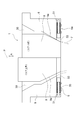
- FIG. 1 what is indicated by reference numeral 1 is a crosshead schematically shown, and a core 9 is vertically moved along an arrow A direction via an actuator (not shown) inside a ring-shaped die 8 of the crosshead 1.
- the left half shows the case where the core 9 is raised to the uppermost position and the right half shows the case where the core 9 is lowered to the lowermost position with the center line P as the center.
- a resin flow path 30 is formed for discharging a multilayered molten resin downward.
- the radial width 2A of the annular discharge port 2 is continuously changed by the vertical movement of the core 9, and the core 9 is most elevated in the left half region from the center line P in FIG.
- the radial width 2A is the smallest, and in the region on the right half from the center line P in FIG. 1, the core 9 is most lowered, so the radial width 2A is configured to be the largest.
- a recess 31 is formed in the lower portion of the core 9 along the diameter direction of the core 9, and a pair of separators 5, 5 a are disposed in the recess 31 so as to face each other along the diameter direction.
- Each of the separators 5, 5 a includes a cylindrical holder 32, a longitudinal separator body 34 having a branch portion 33 on the tip side thereof, a step 32 a of the cylindrical holder 32, and a step 34 a of the separator body 34.
- the urging body 35 is provided between them. The urging force of the urging body 35 urges the branch portion 33 so as to always contact the inner wall 8a of the die 8 directly.
- the urging body 35 can be a coil spring, rubber spring, bellows-like body, linear actuator, or the like located on the outer periphery of the separator body 34.
- the core 9 moves up and down as shown in FIG. Also when adjusting the wall thickness, the branch portion 33 slides in contact with the inner wall 8a of the die 8 while being urged, and the parison 3 is moved along the diameter direction regardless of the wall thickness of the parison 3. It is configured to be bisected.
- the die 8 is configured to be able to move in the horizontal direction with respect to the core 9, and the thickness of the sheet 3 a is changed by decentering the cross-sectional shape of the parison 3 and changing the thickness balance. It can be in various shapes or thicknesses.
- the separators 5 and 5a are provided in the lower part of the core 9 .
- the same effect as described above can be obtained. That is, the branch portion 33 of each separator 5, 5 a is in direct contact with the outer wall 9 a of the core 9.
- the die 8 and the core 9 in FIG. 2 have a resin flow path 30 formed in a reverse taper shape, that is, a funnel shape, as compared with the configuration of FIG. 2, the same parts as those in FIG. 1 are denoted by the same reference numerals, and FIG.
- the crosshead according to the present invention can cut the parison 3 in the crosshead 1, and can be provided with separators 5 and 5a retrofit to an existing crosshead as well as a new one.
Landscapes
- Engineering & Computer Science (AREA)
- Manufacturing & Machinery (AREA)
- Mechanical Engineering (AREA)
- Blow-Moulding Or Thermoforming Of Plastics Or The Like (AREA)
Abstract
本発明は、コア又はダイの下部に設けたセパレータの分岐部をダイ又はコアの内壁に付勢して接触させることにより、パリソンを二分して一対のシートを形成することを目的とする。本発明によるクロスヘッドは、セパレータ(5,5a)が、コア(9)又はダイ(8)の下部の凹部(31)内に設けられ、各セパレータ(5,5a)のセパレータ体(34)の分岐部(33)は付勢体(35)を介してダイ(8)又はコア(9)の内壁(8a)又は外壁(9a)に付勢されて接触してパリソン(3)をシート(7)に切断する構成である。
Description
本発明は、クロスヘッドに関し、特に、コア又はダイの下部に設けた一対のセパレータの分岐部をダイの内壁又はコアの外壁に付勢して接触させることにより、パリソンを二分して一対のシートを形成するための新規な改良に関する。
従来、例えば、自動車用プラスチック燃料タンクは、ガス透過性や各種機能を満足するため、タンク内部にインサート部品を装着するためのスペースを確保するため、従来の円筒状のパリソンではなく、シート状の樹脂やパリソンに切れ目を入れるなどして成形している。
前述のように、パリソンに切れ目を入れてパリソンから一対のシートを得るための従来技術としては、例えば、図3の第1従来例に示される特許文献1の構成を挙げることができる。
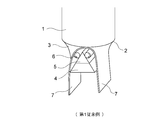
すなわち、図3において符号1で示されるものは押出装置であり、この押出装置1の下部の輪状吐出口2から下方へ吐出されるパリソン3は、この押出装置1の下方へ位置するホルダ4上のボディ5により二分割され、このボディ5の両側に位置する被動ロール6を介して下方へ垂下し、一対のシート7として得ることができる。
前述のように、パリソンに切れ目を入れてパリソンから一対のシートを得るための従来技術としては、例えば、図3の第1従来例に示される特許文献1の構成を挙げることができる。
すなわち、図3において符号1で示されるものは押出装置であり、この押出装置1の下部の輪状吐出口2から下方へ吐出されるパリソン3は、この押出装置1の下方へ位置するホルダ4上のボディ5により二分割され、このボディ5の両側に位置する被動ロール6を介して下方へ垂下し、一対のシート7として得ることができる。
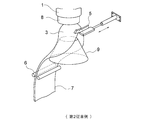
また、第2従来例の特許文献2のプラスチックシートの製造装置においては、図4に示されるように、押出装置1のダイ8から垂下するパリソン3は、ダイ8の下方に位置するセパレータ5によって切断されて一枚のシート7に展開部材9を介して展開されている。
また、第3従来例の特許文献3の中空成形方法においては、図5及び図6に示されるように、押出装置1のダイ8内のコア9を経て吐出されるパリソン3は、コア9の流路規制分岐部材5により分岐された一対のシート7として被動ロール6を介して下方へ垂下し、一対の金型20,21間で部品22と共にインサート成形される。
従来のパリソンからのシートの製造装置は、以上のように構成されていたため、次のような課題が存在していた。
すなわち、図3の特許文献1の構成の場合、クロスヘッドである押出装置1からパリソン3が排出された後に、刃であるボディ5によって二分割に切断されるため、重力が切断のための力になるが、切断デバイスであるボディ5の摩擦が抵抗となり、良好な切断が得られないことがある。
そのため、一対の被動ロール6により切断を補助しなければならなかった。
また、パリソンがボディ5に付着することのないように、ボディ5を冷却しなければならなかった。
また、ボディ5を冷却したために、パリソン3の温度が低くなりすぎると、逆に、パリソン3を加熱しなければ切断できなくなることになっていた。
すなわち、図3の特許文献1の構成の場合、クロスヘッドである押出装置1からパリソン3が排出された後に、刃であるボディ5によって二分割に切断されるため、重力が切断のための力になるが、切断デバイスであるボディ5の摩擦が抵抗となり、良好な切断が得られないことがある。
そのため、一対の被動ロール6により切断を補助しなければならなかった。
また、パリソンがボディ5に付着することのないように、ボディ5を冷却しなければならなかった。
また、ボディ5を冷却したために、パリソン3の温度が低くなりすぎると、逆に、パリソン3を加熱しなければ切断できなくなることになっていた。
また、図4の特許文献2の構成の場合、ダイ8の下方にセパレータ5及び展開部材9を設けなければならず、パリソン3が排出された後からの切断となり、前述の特許文献1と同様の課題が存在していた。
また、パリソン3を切断するための構造が複雑となり、中空成形機の全体形状を小型化することが困難であった。
また、パリソン3を切断するための構造が複雑となり、中空成形機の全体形状を小型化することが困難であった。
また、図5及び図6に示される特許文献3の構成の場合、コア9の外周にセパレータ5が突出して形成されているため、このセパレータ5は厚さを厚くすることができず、パリソン3の厚さを可変とした場合には追従することができず、コア9を種々交換する必要があった。
本発明は、セパレータをクロスヘッドのコア又はダイ内に設け、クロスヘッド内部は樹脂圧力が存在するため、従来の重力と比べ非常に強い力でパリソンを切断することができ、良好な切断を得ることができるクロスヘッドを提供することを目的とする。
本発明は、セパレータをクロスヘッドのコア又はダイ内に設け、クロスヘッド内部は樹脂圧力が存在するため、従来の重力と比べ非常に強い力でパリソンを切断することができ、良好な切断を得ることができるクロスヘッドを提供することを目的とする。
本発明によるクロスヘッドは、ダイ内に上下動自在に配設されたコアと、前記ダイとコア間に形成された輪状吐出口と、前記コア又はダイの下部に設けられ前記輪状吐出口から吐出されるパリソンを二分したシートに形成するための一対のセパレータとからなり、前記各セパレータの分岐部は付勢体を介して前記ダイの内壁又は前記コアの外壁に付勢状態で接触している構成であり、また、前記各セパレータは、前記コアの下部の凹部又は前記ダイの下部の凹部に設けられている構成であり、また、前記コアの上下動により前記輪状吐出口の半径方向幅が変化し、前記パリソンの肉厚が変化した場合でも、前記セパレータによる前記パリソンの切断が行われる構成であり、また、前記各セパレータは、前記コア又はダイの直径方向に沿って互いに対向配置されている構成である。
本発明によるクロスヘッドは、以上のように構成されているため、次のような効果を得ることができる。
すなわち、ダイ内に上下動自在に配設されたコアと、前記ダイとコア間に形成された輪状吐出口と、前記コア又はダイの下部に設けられ前記輪状吐出口から吐出されるパリソンを二分したシートに形成するための一対のセパレータとからなり、前記各セパレータの分岐部は付勢体を介して前記ダイの内壁又は前記コアの外壁に付勢状態で接触していることにより、クロスヘッドの輪状吐出口から吐出されたままのパリソンを温度が低下しない状態で一対のセパレータにより切断され、良好な切断状態の一対のシートを得ることができる。
また、コアの上下動時においても、常時、セパレータの先端がダイの内壁に接して摺動しているため、パリソンの肉厚の変化に拘わらず切断することができる。すなわち、クロスヘッドの下部から押し出されたパリソンを押し出される前に分岐しているため、従来の切断刃の状態、位置に左右されることなく安定かつ綺麗に溶融樹脂をシート状に形成できる。
すなわち、ダイ内に上下動自在に配設されたコアと、前記ダイとコア間に形成された輪状吐出口と、前記コア又はダイの下部に設けられ前記輪状吐出口から吐出されるパリソンを二分したシートに形成するための一対のセパレータとからなり、前記各セパレータの分岐部は付勢体を介して前記ダイの内壁又は前記コアの外壁に付勢状態で接触していることにより、クロスヘッドの輪状吐出口から吐出されたままのパリソンを温度が低下しない状態で一対のセパレータにより切断され、良好な切断状態の一対のシートを得ることができる。
また、コアの上下動時においても、常時、セパレータの先端がダイの内壁に接して摺動しているため、パリソンの肉厚の変化に拘わらず切断することができる。すなわち、クロスヘッドの下部から押し出されたパリソンを押し出される前に分岐しているため、従来の切断刃の状態、位置に左右されることなく安定かつ綺麗に溶融樹脂をシート状に形成できる。
本発明は、コア又はダイの下部に設けたセパレータをダイの内壁又はコアの外壁に摺動させることにより、パリソンを二分して一対のシートを形成するようにしたクロスヘッドを提供することを目的とする。
以下、図面と共に本発明によるクロスヘッドの好適な実施の形態について説明する。
尚、従来例と同一又は同等部分については同一符号を付して説明する。
図1において、符号1で示されるものは概略で示すクロスヘッドであり、このクロスヘッド1の輪状をなすダイ8の内側にはコア9が図示しないアクチュエータを介して矢印Aの方向に沿って上下動できるように構成され、中心線のPを中心として、左半分はコア9が最上位置に上昇した場合を示し、右半分はコア9が最下位置に下降した場合を示している。
尚、従来例と同一又は同等部分については同一符号を付して説明する。
図1において、符号1で示されるものは概略で示すクロスヘッドであり、このクロスヘッド1の輪状をなすダイ8の内側にはコア9が図示しないアクチュエータを介して矢印Aの方向に沿って上下動できるように構成され、中心線のPを中心として、左半分はコア9が最上位置に上昇した場合を示し、右半分はコア9が最下位置に下降した場合を示している。
前記クロスヘッド1のダイ8の内壁8aとコア9の外壁9aとの間には、多層状の溶融樹脂を下方へ吐出するための樹脂流路30が形成され、この樹脂流路30の下部には、パリソン3を吐出するための輪状吐出口2が形成されている。
前記輪状吐出口2の半径方向幅2Aは、前記コア9の上下動により連続的に変化し、図1の中心線Pから左半分の領域においては、コア9が最も上昇しているため、この半径方向幅2Aは最小となり、図1の中心線Pから右半分の領域においては、コア9が最も下降しているため、この半径方向幅2Aは最大となるように構成されている。
前記輪状吐出口2の半径方向幅2Aは、前記コア9の上下動により連続的に変化し、図1の中心線Pから左半分の領域においては、コア9が最も上昇しているため、この半径方向幅2Aは最小となり、図1の中心線Pから右半分の領域においては、コア9が最も下降しているため、この半径方向幅2Aは最大となるように構成されている。
前記コア9の下部には、コア9の直径方向に沿って凹部31が形成され、この凹部31内には一対のセパレータ5,5aが互いに直径方向に沿って互いに対向配置されている。
前記各セパレータ5,5aは、筒状ホルダ32と、その先端側に分岐部33を有する長手状のセパレータ体34と、前記筒状ホルダ32の段部32aとセパレータ体34の段部34aとの間に設けられた付勢体35と、からなり、この付勢体35の付勢力によって前記分岐部33がダイ8の内壁8aに常時直接接触するように付勢されている。
前記各セパレータ5,5aは、筒状ホルダ32と、その先端側に分岐部33を有する長手状のセパレータ体34と、前記筒状ホルダ32の段部32aとセパレータ体34の段部34aとの間に設けられた付勢体35と、からなり、この付勢体35の付勢力によって前記分岐部33がダイ8の内壁8aに常時直接接触するように付勢されている。
前記付勢体35は、セパレータ体34の外周に位置するコイルスプリング、ゴムスプリング、蛇腹状体あるいはリニアアクチュエータ等を用いることができ、図1のように、コア9が上下動してパリソン3の肉厚を調整する場合も、前記分岐部33はダイ8の内壁8aに付勢された状態で接して摺動し、パリソン3の肉厚の大小に拘わらず、パリソン3を直径方向に沿って二分することができるように構成されている。
前述の本発明によるクロスヘッドを用いてパリソンからシートを形成する場合について説明する。
図示しない押出機から押出された溶融樹脂(単層又は多層)は、樹脂流路30を経て輪状吐出口2からパリソン3として下方へ吐出される際に、前記各セパレータ5,5aの各分岐部33がパリソン3を直径方向に沿って切断するため、クロスヘッド1の下部から吐出される時は、一対のシート7が形成される。
従って、パリソン3は、クロスヘッド1内の温度が高い状態のままで切断されるため、極めて円滑に切断動作が行われる。
図示しない押出機から押出された溶融樹脂(単層又は多層)は、樹脂流路30を経て輪状吐出口2からパリソン3として下方へ吐出される際に、前記各セパレータ5,5aの各分岐部33がパリソン3を直径方向に沿って切断するため、クロスヘッド1の下部から吐出される時は、一対のシート7が形成される。
従って、パリソン3は、クロスヘッド1内の温度が高い状態のままで切断されるため、極めて円滑に切断動作が行われる。
また、前記ダイ8は、コア9に対して水平方向に移動することができるように構成され、パリソン3の断面形状を偏芯させ、厚みバランスを変化することにより、前記シート3aの厚さを種々の形状又は肉厚とすることができる。
尚、前述の形態では、各セパレータ5,5aをコア9の下部に設けた場合について述べたが、図2で示されるように、各セパレータ5,5aをダイ8の下部の凹部60に設けた場合も前述と同様の作用効果を得ることができる。すなわち、各セパレータ5,5aの分岐部33がコア9の外壁9aに直接接している。
また、図2におけるダイ8とコア9は図1の構成と比べると樹脂流路30が逆テーパ状、すなわちロート状に形成されている。
尚、図2の構成は図1と同一部分については同一符号を付し、その説明は図1を援用する。
尚、前述の形態では、各セパレータ5,5aをコア9の下部に設けた場合について述べたが、図2で示されるように、各セパレータ5,5aをダイ8の下部の凹部60に設けた場合も前述と同様の作用効果を得ることができる。すなわち、各セパレータ5,5aの分岐部33がコア9の外壁9aに直接接している。
また、図2におけるダイ8とコア9は図1の構成と比べると樹脂流路30が逆テーパ状、すなわちロート状に形成されている。
尚、図2の構成は図1と同一部分については同一符号を付し、その説明は図1を援用する。
本発明によるクロスヘッドは、クロスヘッド1の中でパリソン3を切断することができ、新設だけでなく、既存のクロスヘッドにも後付けでセパレータ5,5aを設けることができる。
Claims (4)
- ダイ(8)内に上下動自在に配設されたコア(9)と、前記ダイ(8)とコア(9)間に形成された輪状吐出口(2)と、前記コア(9)又はダイ(8)の下部に設けられ前記輪状吐出口(2)から吐出されるパリソン(3)を二分したシート(7)に形成するための一対のセパレータ(5,5a)とからなり、
前記各セパレータ(5,5a)の分岐部(33)は付勢体(35)を介して前記ダイ(8)の内壁(8a)又は前記コア(9)の外壁(9a)に付勢状態で接触していることを特徴とするクロスヘッド。 - 前記各セパレータ(5,5a)は、前記コア(9)の下部の凹部(31)又は前記ダイ(8)の下部の凹部(60)に設けられていることを特徴とする請求項1記載のクロスヘッド。
- 前記コア(9)の上下動により前記輪状吐出口(2)の半径方向幅(2A)が変化し、前記パリソン(3)の肉厚が変化した場合でも、前記セパレータ(5,5a)による前記パリソン(3)の切断が行われることを特徴とする請求項1記載のクロスヘッド。
- 前記各セパレータ(5,5a)は、前記コア(9)又はダイ(8)の直径方向に沿って互いに対向配置されていることを特徴とする請求項1ないし3の何れかに記載のクロスヘッド。
Applications Claiming Priority (2)
| Application Number | Priority Date | Filing Date | Title |
|---|---|---|---|
| JP2011-114595 | 2011-05-23 | ||
| JP2011114595A JP2012240362A (ja) | 2011-05-23 | 2011-05-23 | クロスヘッド |
Publications (1)
| Publication Number | Publication Date |
|---|---|
| WO2012160836A1 true WO2012160836A1 (ja) | 2012-11-29 |
Family
ID=47216926
Family Applications (1)
| Application Number | Title | Priority Date | Filing Date |
|---|---|---|---|
| PCT/JP2012/050256 Ceased WO2012160836A1 (ja) | 2011-05-23 | 2012-01-10 | クロスヘッド |
Country Status (2)
| Country | Link |
|---|---|
| JP (1) | JP2012240362A (ja) |
| WO (1) | WO2012160836A1 (ja) |
Cited By (1)
| Publication number | Priority date | Publication date | Assignee | Title |
|---|---|---|---|---|
| JP2017042945A (ja) * | 2015-08-24 | 2017-03-02 | トヨタ自動車株式会社 | 押出装置 |
Families Citing this family (2)
| Publication number | Priority date | Publication date | Assignee | Title |
|---|---|---|---|---|
| JP5721077B2 (ja) * | 2011-12-19 | 2015-05-20 | 株式会社アイテック | ブロー成形用ダイとブロー成形方法 |
| WO2017069011A1 (ja) * | 2015-10-23 | 2017-04-27 | 八千代工業株式会社 | パリソンガイド |
Citations (6)
| Publication number | Priority date | Publication date | Assignee | Title |
|---|---|---|---|---|
| JPH042087B2 (ja) * | 1985-05-15 | 1992-01-16 | ||
| JPH06126817A (ja) * | 1992-10-20 | 1994-05-10 | Inoac Corp | ブロー成形法 |
| JPH06218792A (ja) * | 1993-01-21 | 1994-08-09 | Japan Steel Works Ltd:The | プラスチックシートの製造方法及び装置 |
| JPH07156255A (ja) * | 1993-12-06 | 1995-06-20 | Showa Denko Kk | パネルブロー製品の成形方法 |
| JPH091640A (ja) * | 1995-06-23 | 1997-01-07 | Sekisui Seikei Kogyo Kk | ブロー成形方法及び装置 |
| JP4295213B2 (ja) * | 2002-07-12 | 2009-07-15 | バーゼル・ポリオレフィン・ゲーエムベーハー | 切開パリソンの誘導 |
-
2011
- 2011-05-23 JP JP2011114595A patent/JP2012240362A/ja not_active Withdrawn
-
2012
- 2012-01-10 WO PCT/JP2012/050256 patent/WO2012160836A1/ja not_active Ceased
Patent Citations (6)
| Publication number | Priority date | Publication date | Assignee | Title |
|---|---|---|---|---|
| JPH042087B2 (ja) * | 1985-05-15 | 1992-01-16 | ||
| JPH06126817A (ja) * | 1992-10-20 | 1994-05-10 | Inoac Corp | ブロー成形法 |
| JPH06218792A (ja) * | 1993-01-21 | 1994-08-09 | Japan Steel Works Ltd:The | プラスチックシートの製造方法及び装置 |
| JPH07156255A (ja) * | 1993-12-06 | 1995-06-20 | Showa Denko Kk | パネルブロー製品の成形方法 |
| JPH091640A (ja) * | 1995-06-23 | 1997-01-07 | Sekisui Seikei Kogyo Kk | ブロー成形方法及び装置 |
| JP4295213B2 (ja) * | 2002-07-12 | 2009-07-15 | バーゼル・ポリオレフィン・ゲーエムベーハー | 切開パリソンの誘導 |
Cited By (2)
| Publication number | Priority date | Publication date | Assignee | Title |
|---|---|---|---|---|
| JP2017042945A (ja) * | 2015-08-24 | 2017-03-02 | トヨタ自動車株式会社 | 押出装置 |
| US10201925B2 (en) | 2015-08-24 | 2019-02-12 | Toyota Jidosha Kabushiki Kaisha | Extrusion apparatus |
Also Published As
| Publication number | Publication date |
|---|---|
| JP2012240362A (ja) | 2012-12-10 |
Similar Documents
| Publication | Publication Date | Title |
|---|---|---|
| JP5427834B2 (ja) | クロスヘッド | |
| JP2012240361A5 (ja) | ||
| JP2013049196A (ja) | コアを用いた成形方法および成形装置 | |
| WO2012160836A1 (ja) | クロスヘッド | |
| JP6177101B2 (ja) | ブロー成形方法 | |
| US20170341286A1 (en) | Molding apparatus | |
| CN102173047B (zh) | 一种两片型坯成型方法及其成型组合装置 | |
| JP5913263B2 (ja) | 押出成形装置及び熱可塑性エラストマー成形品の製造方法 | |
| JP7183190B2 (ja) | 一体形血清ピペットを形成する方法 | |
| US20160263810A1 (en) | Blow film line and method for operating a blow film line | |
| JP6491290B2 (ja) | 樹脂成形品の製造方法 | |
| JP2013049186A (ja) | 樹脂製熱伝達ユニットの製造方法 | |
| JP6296021B2 (ja) | 押出装置 | |
| CN205572981U (zh) | 一种塑料管材真空定型套 | |
| JP2018094726A (ja) | パリソン移送装置 | |
| JP2015080869A (ja) | パリソン搬送装置 | |
| JP7502634B2 (ja) | 樹脂シートの製造方法、押出ヘッド | |
| US11179866B2 (en) | Parison separation device, blow molding machine, and method for manufacturing blow-molded article | |
| JP5688247B2 (ja) | 樹脂発泡シートの製造方法、及び、押出設備の改修方法 | |
| JP2010131625A (ja) | フランジ付きカップ製品の成形方法 | |
| WO2015075527A1 (en) | Apparatus for manufacturing resin sheet, method for manufacturing resin sheet, and method for manufacturing fuel tank | |
| JP2014014974A (ja) | シート成形用ロール対、シート成形装置およびシート製造方法 | |
| JP2018111274A (ja) | 樹脂成形品の製造装置 | |
| JP2013126731A (ja) | ブロー成形用ダイとブロー成形方法 | |
| CN107073766A (zh) | 单位层叠橡胶的制造装置和单位层叠橡胶的制造方法 |
Legal Events
| Date | Code | Title | Description |
|---|---|---|---|
| 121 | Ep: the epo has been informed by wipo that ep was designated in this application |
Ref document number: 12789903 Country of ref document: EP Kind code of ref document: A1 |
|
| NENP | Non-entry into the national phase |
Ref country code: DE |
|
| 122 | Ep: pct application non-entry in european phase |
Ref document number: 12789903 Country of ref document: EP Kind code of ref document: A1 |