WO2012157254A1 - ラマン分光測定方法および装置 - Google Patents
ラマン分光測定方法および装置 Download PDFInfo
- Publication number
- WO2012157254A1 WO2012157254A1 PCT/JP2012/003153 JP2012003153W WO2012157254A1 WO 2012157254 A1 WO2012157254 A1 WO 2012157254A1 JP 2012003153 W JP2012003153 W JP 2012003153W WO 2012157254 A1 WO2012157254 A1 WO 2012157254A1
- Authority
- WO
- WIPO (PCT)
- Prior art keywords
- enhanced raman
- spectroscopic measurement
- sample
- raman spectroscopic
- transparent substrate
- Prior art date
- Legal status (The legal status is an assumption and is not a legal conclusion. Google has not performed a legal analysis and makes no representation as to the accuracy of the status listed.)
- Ceased
Links
Images


Classifications
-
- G—PHYSICS
- G01—MEASURING; TESTING
- G01N—INVESTIGATING OR ANALYSING MATERIALS BY DETERMINING THEIR CHEMICAL OR PHYSICAL PROPERTIES
- G01N21/00—Investigating or analysing materials by the use of optical means, i.e. using sub-millimetre waves, infrared, visible or ultraviolet light
- G01N21/62—Systems in which the material investigated is excited whereby it emits light or causes a change in wavelength of the incident light
- G01N21/63—Systems in which the material investigated is excited whereby it emits light or causes a change in wavelength of the incident light optically excited
- G01N21/65—Raman scattering
-
- G—PHYSICS
- G01—MEASURING; TESTING
- G01N—INVESTIGATING OR ANALYSING MATERIALS BY DETERMINING THEIR CHEMICAL OR PHYSICAL PROPERTIES
- G01N21/00—Investigating or analysing materials by the use of optical means, i.e. using sub-millimetre waves, infrared, visible or ultraviolet light
- G01N21/62—Systems in which the material investigated is excited whereby it emits light or causes a change in wavelength of the incident light
- G01N21/63—Systems in which the material investigated is excited whereby it emits light or causes a change in wavelength of the incident light optically excited
- G01N21/65—Raman scattering
- G01N21/658—Raman scattering enhancement Raman, e.g. surface plasmons
Definitions
- the present invention relates to a Raman spectroscopic measurement apparatus, and more particularly to a surface-enhanced Raman spectroscopic measurement apparatus that can detect and detect Raman scattered light by a metal body.
- the present invention also relates to a surface-enhanced Raman spectroscopic measurement method performed using such a Raman spectroscopic measurement apparatus.
- Raman spectroscopic measurement for identifying and detecting substances contained in a sample by applying the Raman effect is known.
- the Raman effect is a phenomenon in which light having a wavelength different from that of incident light is scattered when light is incident on a substance.
- Raman spectroscopy uses this phenomenon to irradiate a sample with light of a single wavelength, and spectroscopically detect the Raman scattered light generated at that time to identify a specific substance.
- SERS surface-enhanced Raman spectroscopy
- This surface-enhanced Raman spectroscopic measurement is based on the fact that the intensity of Raman scattered light is enhanced when light is applied to a material in contact with a metal body having fine irregularities on the surface, so that a very small amount of material is used. Is also made detectable.
- Patent Documents 1 and 2 and Non-Patent Document 1 disclose examples of apparatuses that perform this surface-enhanced Raman spectroscopic measurement.
- a conventional surface-enhanced Raman spectroscopic measurement apparatus disclosed in Patent Document 1 irradiates a sample in contact with a metal body formed on a substrate surface with measurement light from the substrate surface side, and the Raman scattered light generated at that time. Is detected from the measurement light irradiation side. Therefore, in a conventional surface-enhanced Raman spectroscopic measurement apparatus, it has been extremely difficult to directly perform spectroscopic measurement of a sample developed on a filter paper by paper chromatography or an opaque sample such as a biological section.
- the present invention has been made in view of the above circumstances, and an object thereof is to provide a surface-enhanced Raman spectroscopic measurement apparatus and a surface-enhanced Raman spectroscopic measurement method capable of easily measuring an opaque sample.
- the surface enhanced Raman spectrometer comprises A transparent substrate; A metal body formed on one surface of the transparent substrate and causing surface-enhanced Raman scattering; A pressing mechanism for pressing the sample body arranged in contact with the metal body against the metal body side; A measurement light irradiation optical system for irradiating the sample body with measurement light through the transparent substrate; And a light detection means for spectrally detecting Raman scattered light generated when the sample body is irradiated with measurement light through the transparent substrate.
- sample body may be a sample to be measured (particularly a solid sample) itself, or may be a liquid sample developed on a liquid permeable substance such as filter paper.
- a positioning member that holds the transparent substrate at a predetermined position against the pressing force by the pressing mechanism is provided.
- a mechanism composed of a plate-like member in contact with the sample body and spring means for urging the plate-like member toward the metal body side is preferably used.
- the metal body has a concavo-convex structure in which the size of the concavo-convex portion is smaller than the wavelength of the measurement light.
- the main component of the metal body is preferably at least one metal selected from the group consisting of Au, Ag, Cu, Al, Pt, Ni, Ti, and alloys thereof.
- the surface-enhanced Raman spectroscopic measurement method according to the present invention is characterized by performing Raman spectroscopic measurement using the above-described surface-enhanced Raman spectroscopic measurement apparatus of the present invention.
- a liquid permeable material made of, for example, filter paper impregnated with a liquid sample can be used as the sample body.
- liquid samples impregnated in a plurality of locations of the liquid permeable substance are separated from each other by chromatography.
- the sample body may be a solid sample itself such as a biological section. Even when the solid sample itself is used as described above, it is desirable to individually irradiate the measurement light to a plurality of locations on the solid sample and detect the Raman scattered light generated at each irradiation.
- a transparent substrate a metal body formed on one surface of the transparent substrate, which causes surface-enhanced Raman scattering, and a sample disposed in contact with the metal body
- a pressing mechanism that presses the body against the metal body, a measurement light irradiation optical system that irradiates the sample body with measurement light through the transparent substrate, and a Raman scattering light generated when the measurement light is irradiated to the sample.
- the light detection means for spectrally detecting through it is possible to irradiate measurement light through a transparent substrate even with an opaque sample body, and it is possible to spectrally detect the Raman scattered light generated at that time through the transparent substrate, Surface-enhanced Raman spectroscopic measurement can be easily performed even on an opaque sample body.
- the surface-enhanced Raman spectroscopic measurement method according to the present invention performs Raman spectroscopic measurement using the surface-enhanced Raman spectroscopic measurement device having the above-described configuration. Therefore, according to this method, an opaque sample body can be easily obtained. Surface enhanced Raman spectroscopy can be performed.
- a plurality of locations of the liquid permeable substance are impregnated with a liquid sample, and the plurality of locations are individually irradiated with measurement light, and the Raman generated for each irradiation is generated.
- the Raman generated for each irradiation is generated.
- the surface-enhanced Raman spectroscopic measurement method of the present invention in particular, when a plurality of locations of a solid sample are individually irradiated with measurement light and Raman scattered light generated for each irradiation is detected, specific components in the solid sample are detected. It becomes possible to efficiently obtain the distribution of concentration and the like.
- FIG. 1 is a schematic side view showing a surface enhanced Raman spectrometer according to an embodiment of the present invention.
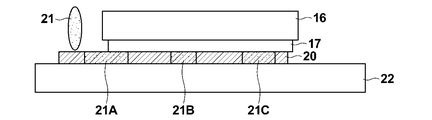
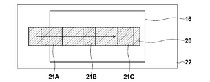
- FIG. 1 is a plan view showing a part of the apparatus of FIG. Side view for explaining one step of Raman spectroscopic measurement performed using the apparatus of FIG.
- FIG. 1 is a plan view for explaining one step of Raman spectroscopic measurement performed using the apparatus of FIG.
- FIG. 1 shows a schematic side shape of a surface-enhanced Raman spectrometer 10 according to an embodiment of the present invention.
- this surface-enhanced Raman spectroscopic measurement apparatus 10 includes a light source 12 such as a semiconductor laser that emits measurement light 11 and a collimator that collimates the measurement light 11 emitted from the light source 12 in a divergent light state.
- a lens 13 a condensing lens 14 for converging the measurement light 11 that has become parallel light on a measurement surface, which will be described later, a beam splitter 15 disposed between the condensing lens 14 and the collimator lens 13, for example, an optical A transparent substrate 16 made of glass or the like, and a metal layer 17 having a fine concavo-convex structure formed on one surface of the transparent substrate 16, that is, the lower surface in the figure.
- the surface-enhanced Raman spectroscopic measurement apparatus 10 includes a positioning member 18 that abuts on the upper surface of the transparent substrate 16 to define the upper position of the transparent substrate 16, and the metal layer disposed below the transparent substrate 16.
- a glass substrate 22 that sandwiches the filter paper 20 between the substrate 17, a substrate holding plate 23 on which the glass substrate 22 is placed and fixed, and a base disposed below the substrate holding plate 23 via a plurality of plate springs 24. And a table 25.
- the surface-enhanced Raman spectroscopic measurement apparatus 10 includes a measurement light cut filter 26 disposed on the side of the beam splitter 15 and a spectroscopic method for spectrally detecting Raman scattered light (described later) transmitted through the measurement light cut filter 26. And a data processing means 28 comprising, for example, a computer system for processing the output of the spectroscope 27.
- the metal layer 17 includes, for example, a thin film forming step of forming a thin film made of a first metal or metal oxide on the transparent substrate 16, and a hydrothermal reaction of the thin film to cause the first metal or metal oxide to be formed.
- a fine concavo-convex structure layer forming step of forming a fine concavo-convex structure layer made of a hydroxide, and a metal layer preparation step of forming a metal fine concavo-convex structure layer made of a second metal on the surface of the fine concavo-convex structure layer Can be formed.
- the second metal is preferably gold (Au), silver (Ag), copper (Cu), aluminum (Al), platinum (Pt), or an alloy containing these as a main component.
- Au or Ag is preferable.
- a metal vapor deposition method can be applied to the metal layer manufacturing process for forming the metal layer made of the second metal.
- the vapor deposition film thickness is desirably 30 nm or more.
- the vapor deposition film thickness is desirably 150 nm or less.
- a metal fine particle dispersion step of dispersing metal fine particles made of the second metal on the surface of the fine concavo-convex structure layer may be applied. In that case, it is preferable to use metal fine particles having a diameter of 100 nm or less.
- the first metal for example, aluminum (Al) can be used, and as the metal oxide, alumina (Al 2 O 3 ) can be used.
- the hydroxide is preferably composed of at least one of buyerite and boehmite.
- the metal layer 17 is not limited to the one formed from each of the above steps, and may be a metal layer having a roughened surface, for example.
- Examples of the roughening method include an electrochemical method using oxidation reduction and the like.
- the metal layer 17 may be composed of other known structures.
- J.AM.CHEM.SOC. 2005, Vol.127, 14992-14993 “Nanosphere arrays with controlled sub-10-nm gaps as surface-enhanced raman spectroscopy substrates”
- a CTAB cetyltrimethylammonium A metal layer formed by arranging a plurality of Au particles surface-modified with bromide
- Japanese Patent Laid-Open No. 2005-233637 discloses a metal layer formed by forming a gold nanorod thin film on a substrate. In the present invention, these metal layers can be used as appropriate.
- the operation of the surface enhanced Raman spectroscopic measurement apparatus 10 having the above-described configuration will be described.
- the filter paper 20 is placed on the glass substrate 22.
- the filter paper 20 is arranged in a state where one end of the filter paper 20 protrudes laterally from the side edge of the transparent substrate 16.
- the filter paper 20 is sandwiched between the metal layer 17 on the surface of the transparent substrate 16 and the glass substrate 22.
- the transparent substrate 16 since the upper surface of the transparent substrate 16 contacts the positioning member 18, the transparent substrate 16 stays at a predetermined vertical position against the pressing force of the leaf spring 24. Thus, the filter paper 20 is set at a predetermined vertical position.
- the liquid sample 21 is dropped onto one end of the filter paper 20 using a dropping means 30 such as a pipette.
- the dropped liquid sample 21 penetrates almost the entire length in the filter paper 20.
- the filter paper 20 may be set after the liquid sample 21 has permeated the filter paper 20.
- the light source 12 After infiltrating the liquid sample 21 into the filter paper 20 as described above, the light source 12 is turned on, and the measurement light 11 such as a laser beam emitted from the light source 12 passes through the transparent substrate 16 to the filter paper 20 as the measurement surface. Irradiation is performed so as to converge on the surface (which is a surface in contact with the metal layer 17). By the irradiation of the measurement light 11, Raman scattered light is generated from the filter paper 20. The Raman scattered light passes through the transparent substrate 16 and is collected by the condenser lens 14 as shown by a one-dot chain line in FIG. 1, reflected by the beam splitter 15, passes through the measurement light cut filter 26, and passes to the spectroscope 27. Incident.
- the Raman scattered light has a wavelength different from that of the measurement light 11, and the difference in wavelength between the two lights, that is, the energy difference, corresponds to the molecular structure or crystal structure of the analysis target substance contained in the liquid sample 21. Will be.
- the spectroscope 27 spectrally detects the Raman scattered light and inputs the detection result to the data processing means 28.
- the data processing means 28 identifies the analysis target substance contained in the liquid sample 21 based on the input spectral detection result.
- the filter paper 20 impregnated with the liquid sample is in contact with the metal layer 17, the filter paper 20 is irradiated with the measurement light 11, so that the Raman scattered light is significantly enhanced and detected. be able to.
- the measurement light cut filter 26 may be a notch filter or a short wavelength cut filter that transmits Raman scattered light while blocking the measurement light 11 reflected by the measurement surface.
- the light detection means for spectrally detecting Raman scattered light includes the beam splitter 15, the measurement light cut filter 26, and the spectrometer 27.
- the filter paper 20 impregnated with the liquid sample 21 is held between the transparent substrate 16 and the glass substrate 22 and then the filter paper 20 is attached.
- the measurement light 11 is irradiated through the transparent substrate 16 and the Raman scattered light is spectrally detected through the transparent substrate 16. Therefore, even if the filter paper 20 as the sample body is opaque, the Raman spectroscopic measurement on the liquid sample 21 can be easily performed without the Raman scattered light being blocked by the filter paper 20.
- the transparent substrate 16 contacts the positioning member 18, and the vertical position thereof, that is, the vertical position of the filter paper 20 is maintained at a predetermined position. Therefore, even if the filter paper 20 swells, the position of the measurement surface where the measurement light 11 should converge, that is, the upper surface position of the filter paper 20 is always maintained at a predetermined position.
- the surface enhanced Raman spectroscopic measurement apparatus 10 of the present embodiment is suitably used for liquid samples separated from each other by chromatography, particularly paper chromatography.
- chromatography particularly paper chromatography.
- 3 and 4 show the side shape and the planar shape of the part of the filter paper 20 impregnated with the liquid samples 21A, 21B and 21C separated from each other, respectively.
- the liquid sample 21 is dropped on the end of the filter paper 20 as shown in FIG. 3, the liquid sample 21 is separated by paper chromatography as shown by 21A, 21B and 21C according to the different components contained therein. Then, the filter paper 20 is impregnated and held.
- a plurality of locations on the filter paper 20 impregnated and held with the liquid samples 21A, 21B, and 21C are individually irradiated with the measurement light 11 with the configuration of FIG. 1, and the Raman scattered light generated for each irradiation is spectrally detected. By doing so, it becomes possible to efficiently perform Raman spectroscopic measurement for a plurality of components contained in the liquid sample 21.
- the measurement light irradiation optical system is entirely moved in the length direction of the filter paper 20, or conversely, the measurement light irradiation
- the optical system may be fixed and the mechanism holding the filter paper 20 may be moved.
- the embodiment in which the filter paper 20 impregnated with the liquid sample 21 is used as the sample body has been described.
- the surface-enhanced Raman spectroscopic measurement method of the present invention is not limited thereto, and a solid sample itself such as a slice of a living body can be used as the sample body. It is also applicable to In that case, a solid sample may be arranged in place of the filter paper 20 in the configuration of FIG.
Landscapes
- Health & Medical Sciences (AREA)
- Nuclear Medicine, Radiotherapy & Molecular Imaging (AREA)
- Physics & Mathematics (AREA)
- Life Sciences & Earth Sciences (AREA)
- Chemical & Material Sciences (AREA)
- Analytical Chemistry (AREA)
- Biochemistry (AREA)
- General Health & Medical Sciences (AREA)
- General Physics & Mathematics (AREA)
- Immunology (AREA)
- Pathology (AREA)
- Investigating, Analyzing Materials By Fluorescence Or Luminescence (AREA)
- Investigating Or Analysing Materials By Optical Means (AREA)
Abstract
【課題】不透明な試料についての測定を簡便に行うことができる表面増強ラマン分光測定装置を得る。 【解決手段】透明基板(16)と、この透明基板(16)の一表面に形成された、表面増強ラマン散乱を生じさせる金属体(17)と、この金属体(17)に接する状態に配置された試料体(20、21)を、該金属体(17)側に押し付ける押圧機構(22,23,24)と、前記透明基板(16)を通して試料体(20、21)に測定光(11)を照射する測定光照射光学系(12,13,14)と、試料体(20,21)に測定光(11)が照射されたとき発生したラマン散乱光を、透明基板(16)を通して分光検出する光検出手段(15,26,27)とから表面増強ラマン分光測定装置(10)を構成する。
Description
本発明はラマン分光測定装置、特に詳細には、金属体によりラマン散乱光を増強して検出可能とした表面増強ラマン分光測定装置に関するものである。
また本発明は、そのようなラマン分光測定装置を利用して行われる表面増強ラマン分光測定方法に関するものである。
従来、ラマン効果を応用して試料中に含まれる物質を同定、検出するラマン分光測定が知られている。ラマン効果は、物質に光を入射させたとき、入射光とは異なる波長の光が散乱される現象であり、その散乱光(ラマン散乱光)と入射させた光との間のエネルギー差つまり波長の差は、物質の分子構造や結晶構造に対応したものとなる。ラマン分光測定はこの現象を利用し、単一波長の光を試料に照射し、そのとき発生したラマン散乱光を分光検出して、特定物質の同定等を行うものである。
また最近では、ラマン散乱光を著しく増強して検出することができる表面増強ラマン分光測定(surface enhanced Raman scattering :SERS)が提案され、広く研究がなされている。この表面増強ラマン分光測定は、表面に微細な凹凸を有する金属体に接触させた状態の物質に光を照射すると、ラマン散乱光の強度が増強されることを利用して、極く少量の物質も検出可能にしたものである。特許文献1、2や非特許文献1には、この表面増強ラマン分光測定を行う装置の例が開示されている。
Optics Express Vol.17, No.2118556
特許文献1等に示される従来の表面増強ラマン分光測定装置は、基板表面に形成された金属体に接触している試料にこの基板表面側から測定光を照射し、そのとき生じたラマン散乱光を測定光照射側から検出するように構成されている。そのため、従来の表面増強ラマン分光測定装置においては、ペーパークロマトグラフィによりろ紙上に展開された試料や、生体切片などの不透明試料を直接分光測定することが極めて困難になっていた。
本発明は上記の事情に鑑みてなされたものであり、不透明な試料についての測定を簡便に行うことができる表面増強ラマン分光測定装置および表面増強ラマン分光測定方法を提供することを目的とする。
本発明による表面増強ラマン分光測定装置は、
透明基板と、
この透明基板の一表面に形成された、表面増強ラマン散乱を生じさせる金属体と、
この金属体に接する状態に配置された試料体を、該金属体側に押し付ける押圧機構と、
前記透明基板を通して前記試料体に測定光を照射する測定光照射光学系と、
前記試料体に測定光が照射されたとき発生したラマン散乱光を、前記透明基板を通して分光検出する光検出手段とを備えたことを特徴とするものである。
透明基板と、
この透明基板の一表面に形成された、表面増強ラマン散乱を生じさせる金属体と、
この金属体に接する状態に配置された試料体を、該金属体側に押し付ける押圧機構と、
前記透明基板を通して前記試料体に測定光を照射する測定光照射光学系と、
前記試料体に測定光が照射されたとき発生したラマン散乱光を、前記透明基板を通して分光検出する光検出手段とを備えたことを特徴とするものである。
なお上記の試料体は、測定対象である試料(特に固体試料)そのものであってもよいし、あるいは液体試料がろ紙等の液体浸透性物質に展開されてなるものであってもよい。
また本発明の表面増強ラマン分光測定装置においては、前記透明基板を、前記押圧機構による押圧力に抗して所定位置に留める位置決め部材が設けられることが特に望ましい。
また前記押圧機構としては、試料体に接する板状部材と、この板状部材を前記金属体側に向けて付勢するばね手段とからなるものが好適に用いられる。
また前記金属体は、測定光の波長よりも凹凸部分のサイズが小さい凹凸構造を有するものが適用されることが望ましい。
また前記金属体の主成分は、Au、Ag、Cu、Al、Pt、Ni、Ti、およびこれらの合金からなる群より選択される少なくとも1種の金属であることが望ましい。
他方、本発明による表面増強ラマン分光測定方法は、上述した本発明の表面増強ラマン分光測定装置を用いてラマン分光測定を行うことを特徴とするものである。
この本発明による表面増強ラマン分光測定方法においては、試料体として、例えば液体試料を含浸した、ろ紙等からなる液体浸透性物質を用いることができる。
このように、液体試料を含浸した液体浸透性物質を用いる場合は、その液体浸透性物質の複数箇所にそれぞれ液体試料を含浸させ、それらの複数箇所に測定光を個別に照射して、各照射毎に発生したラマン散乱光を検出することが望ましい。
なお、上述のように液体浸透性物質の複数箇所にそれぞれ含浸させる液体試料は、クロマトグラフィにより互いに分離されたものであるのが望ましい。
また前記試料体は、生体の切片などの固体の試料そのものであってもよい。このように固体の試料そのものを用いる場合も、固体試料の複数箇所に測定光を個別に照射して、各照射毎に発生したラマン散乱光を検出することが望ましい。
本発明による表面増強ラマン分光測定装置によれば、透明基板と、この透明基板の一表面に形成された、表面増強ラマン散乱を生じさせる金属体と、この金属体に接する状態に配置された試料体を、該金属体側に押し付ける押圧機構と、前記透明基板を通して前記試料体に測定光を照射する測定光照射光学系と、前記試料に測定光が照射されたとき発生したラマン散乱光を透明基板を通して分光検出する光検出手段とを備えたことにより、不透明な試料体でも透明基板を通して測定光を照射することができ、またそのとき発生したラマン散乱光を透明基板を通して分光検出可能であるので、不透明な試料体に対しても簡便に表面増強ラマン分光測定を実施可能となる。
また本発明による表面増強ラマン分光測定方法は、上記構成の表面増強ラマン分光測定装置を用いてラマン分光測定を行うものであるから、この方法によれば、不透明な試料体に対しても簡便に表面増強ラマン分光測定を実施可能となる。
なお、本発明の表面増強ラマン分光測定方法において特に、液体浸透性物質の複数箇所にそれぞれ液体試料を含浸させ、それらの複数箇所に測定光を個別に照射して、各照射毎に発生したラマン散乱光を検出する場合は、液体試料が含んでいる複数成分に対するラマン分光測定を能率良く実施可能となる。
また、本発明の表面増強ラマン分光測定方法において特に、固体試料の複数箇所に測定光を個別に照射して、各照射毎に発生したラマン散乱光を検出する場合は、固体試料における特定成分の濃度等の分布を能率良く求めることが可能になる。
以下、図面を参照して本発明の実施形態を詳細に説明する。図1は、本発明の一実施形態による表面増強ラマン分光測定装置10の概略側面形状を示すものである。図示されるようにこの表面増強ラマン分光測定装置10は、測定光11を発する例えば半導体レーザなどの光源12と、この光源12から発散光状態で発せられた測定光11を平行光化するコリメーターレンズ13と、平行光となった測定光11を後述する測定面上で収束させる集光レンズ14と、この集光レンズ14およびコリメーターレンズ13の間に配置されたビームスプリッタ15と、例えば光学ガラス等からなる透明基板16と、この透明基板16の一表面つまり図中の下表面の上に形成された微細凹凸構造を有する金属層17とを有している。
またこの表面増強ラマン分光測定装置10は、上記透明基板16の上表面に当接してこの透明基板16の上方位置を規定する位置決め部材18と、透明基板16の下側に配置されて上記金属層17との間にろ紙20を挟持するガラス基板22と、このガラス基板22を載置固定した基板保持板23と、この基板保持板23の下方に複数の板ばね24を介して配置されたベース台25とを有している。
さらにこの表面増強ラマン分光測定装置10は、上記ビームスプリッタ15の側方に配置された測定光カットフィルタ26と、この測定光カットフィルタ26を透過して来る後述のラマン散乱光を分光検出する分光器27と、この分光器27の出力を処理する例えばコンピュータシステムからなるデータ処理手段28とを有している。
上記金属層17は、例えば透明基板16の上に第1の金属または金属酸化物からなる薄膜を形成する薄膜形成工程と、上記薄膜を水熱反応させることにより上記第1の金属または金属酸化物の水酸化物からなる微細凹凸構造層を形成する微細凹凸構造層作製工程と、該微細凹凸構造層の表面に、第2の金属から成る金属微細凹凸構造層を形成する金属層作製工程とから形成することができる。
なお上記第2の金属としては、金(Au),銀(Ag),銅(Cu),アルミニウム(Al)、プラチナ(Pt)またはこれらを主成分とする合金であることが好ましい。特に、AuあるいはAgが好ましい。また上記第2の金属からなる金属層を形成する金属層作製工程には、例えば金属蒸着法を適用することができる。そのように蒸着法を適用し、また第2の金属として金を用いる場合、蒸着膜厚は30nm以上とすることが望ましい。あるいは、蒸着法を適用し、第2の金属として銀を用いる場合、蒸着膜厚は150nm以下とすることが望ましい。
また、前記金属層作製工程として、前記微細凹凸構造層の表面に前記第2の金属からなる金属微粒子を分散させる、金属微粒子分散工程を適用してもよい。その場合、金属微粒子としては、直径100nm以下のものを用いることが好ましい。
また、前記第1の金属としては、例えばアルミニウム(Al)、前記金属酸化物としてアルミナ(Al2O3)を用いることができる。
他方、前記水酸化物は、バイヤーマイトおよびベーマイトの少なくとも一方からなるものであることが望ましい。
さらに上記金属層17は、上述の各工程から形成するものに限らず、例えば表面が粗面化された金属層であってもよい。粗面化方法としては、酸化還元等を利用した電気化学的な方法等が挙げられる。
さらに金属層17は、その他の公知の構造からなるものでもよい。例えば、J.AM.CHEM.SOC. 2005, Vol.127, 14992-14993, ”Nanosphere arrays with controlled sub-10-nm gaps as surface-enhanced raman spectroscopy substrates”には、ITO基板上に、CTAB(cetyltrimethylammonium bromide)で表面修飾した複数のAu粒子を配列させてなる金属層が示されており、また特開2005-233637号公報には、基板上に金ナノロッド薄膜を形成してなる金属層が開示されており、本発明においてはそれらの金属層も適宜用いることができる。
以下、上記構成を有する表面増強ラマン分光測定装置10の作用について説明する。ラマン分光測定に際しては、まずガラス基板22および基板保持板23を板ばね24の押圧力に抗して下方に押し下げ、該ガラス基板22の上にろ紙20が載置される。このとき、ろ紙20は図2に示すように、その一端部が透明基板16の側端よりも側方に飛び出た状態に配置される。この状態でガラス基板22および基板保持板23の押し下げを解除すると、透明基板16の表面の金属層17とガラス基板22との間にろ紙20が挟持された状態になる。
なお、このとき透明基板16の上表面が位置決め部材18に当接するので、透明基板16は板ばね24の押圧力に抗して所定の上下位置に留まることになる。こうしてろ紙20は、所定の上下位置にセットされるようになる。
ろ紙20が上述のようにセットされた後、このろ紙20の一端部に、ピペットなどの滴下手段30を用いて液体試料21が滴下される。この滴下された液体試料21は、ろ紙20内において、ほぼその全長に亘って浸透するようになる。なお、このようにろ紙20をセットした後に液体試料21を滴下する他、液体試料21をろ紙20に浸透させた後にろ紙20をセットするようにしても構わない。
以上の通りにして液体試料21をろ紙20に浸透させた後、光源12がONにされ、そこから発せられたレーザ光等の測定光11が、透明基板16を通して、測定面であるろ紙20の表面(これは金属層17に接している面である)上で収束するように照射される。
この測定光11の照射により、ろ紙20の部分からラマン散乱光が生じる。このラマン散乱光は図1に一点鎖線で示すように透明基板16を透過して集光レンズ14により集光され、ビームスプリッタ15で反射し、測定光カットフィルタ26を透過して分光器27に入射する。
この測定光11の照射により、ろ紙20の部分からラマン散乱光が生じる。このラマン散乱光は図1に一点鎖線で示すように透明基板16を透過して集光レンズ14により集光され、ビームスプリッタ15で反射し、測定光カットフィルタ26を透過して分光器27に入射する。
上記ラマン散乱光は、測定光11とは異なる波長のものであり、それら2つの光の間の波長の差つまりエネルギー差は、液体試料21に含まれる分析対象物質の分子構造や結晶構造に対応したものとなる。分光器27はラマン散乱光を分光検出し、その検出結果をデータ処理手段28に入力する。データ処理手段28は入力された分光検出結果に基づいて、液体試料21に含まれる分析対象物質の同定等を行う。
ここで本装置においては、液体試料を含浸しているろ紙20を金属層17に接触させた状態で該ろ紙20に測定光11を照射しているので、ラマン散乱光を著しく増強して検出することができる。
なお上記測定光カットフィルタ26としては、ラマン散乱光を透過させる一方、測定面で反射した測定光11は遮断するノッチフィルタや、あるいは短波長カットフィルタなどが用いられる。
本実施形態では、以上の説明から明らかな通り、ラマン散乱光を分光検出する光検出手段がビームスプリッタ15、測定光カットフィルタ26および分光器27から構成されている。
以上説明した通り本実施形態の表面増強ラマン分光測定装置10においては、液体試料21を含浸しているろ紙20を透明基板16とガラス基板22との間に保持した上で、ろ紙20に対して透明基板16を通して測定光11を照射し、そしてラマン散乱光を透明基板16を通して分光検出するようにしている。そこで、試料体としてのろ紙20が不透明なものであっても、ろ紙20によってラマン散乱光が遮られるようなことなく、液体試料21に対するラマン分光測定を簡便に行うことが可能である。
また本実施形態では、透明基板16が位置決め部材18に当接し、その上下位置つまりろ紙20の上下位置が所定位置に維持される。そこで、ろ紙20が膨潤するようなことがあっても、測定光11を収束させるべき測定面の位置、すなわちろ紙20の上面位置は、常に所定の位置に保たれるようになる。
また、本実施形態の表面増強ラマン分光測定装置10は、クロマトグラフィ、特にペーパークロマトグラフィにより互いに分離された液体試料に対して、好適に用いられるものである。以下、この点について図3および4を用いて説明する。なおこれらの図3および4において、図1および2中の要素と同等の要素には同番号を付してあり、それらについての説明は特に必要のない限り省略する。
図3および4はそれぞれ、互いに分離された液体試料21A、21Bおよび21Cを含浸しているろ紙20の部分の側面形状、平面形状を示している。図3に示すように液体試料21がろ紙20の端部に滴下された後、該液体試料21はペーパークロマトグラフィにより、含んでいる互いに異なる成分に応じて、21A、21Bおよび21Cで示すように分離してろ紙20に含浸保持される。
そこで、液体試料21A、21Bおよび21Cを各々含浸保持しているろ紙20の複数箇所に、図1の構成により測定光11を個別に照射して、各照射毎に発生したラマン散乱光を分光検出すれば、液体試料21が含んでいる複数成分に対するラマン分光測定を能率良く実施可能となる。
なお、上述のようにろ紙20の複数箇所に測定光11を個別に照射するには、例えば測定光照射光学系を全体的にろ紙20の長さ方向に移動させたり、あるいは反対に測定光照射光学系は固定しておいて、ろ紙20を保持している側の機構を移動させるようにすればよい。
以上、液体試料21を含浸させたろ紙20を試料体とする実施形態について説明したが、本発明の表面増強ラマン分光測定方法はそれに限らず、例えば生体のスライスなどの固体試料そのものを試料体とする場合にも適用可能である。その場合は、図1の構成において、ろ紙20に代えて固体試料を配置すればよい。
その場合、固体試料の複数箇所に測定光を個別に照射して、各照射毎に発生したラマン散乱光を検出すれば、固体試料における特定成分の濃度等の分布を能率良く求めることが可能になる。
Claims (12)
- 透明基板と、
この透明基板の一表面に形成された、表面増強ラマン散乱を生じさせる金属体と、
この金属体に接する状態に配置された試料体を、該金属体側に押し付ける押圧機構と、 前記透明基板を通して前記試料体に測定光を照射する測定光照射光学系と、
前記試料体に測定光が照射されたとき発生したラマン散乱光を、前記透明基板を通して分光検出する光検出手段とを備えたことを特徴とする表面増強ラマン分光測定装置。 - 前記透明基板を、前記押圧機構による押圧力に抗して所定位置に留める位置決め部材が設けられたことを特徴とする請求項1記載の表面増強ラマン分光測定装置。
- 前記押圧機構が、前記試料体に接する板状部材と、この板状部材を前記金属体側に向けて付勢するばね手段とからなるものであることを特徴とする請求項1または2記載の表面増強ラマン分光測定装置。
- 前記金属体が、前記測定光の波長よりも凹凸部分のサイズが小さい凹凸構造を有するものであることを特徴とする請求項1から3いずれか1項記載の表面増強ラマン分光測定装置。
- 前記金属体の主成分が、Au、Ag、Cu、Al、Pt、Ni、Ti、およびこれらの合金からなる群より選択される少なくとも1種の金属であることを特徴とする請求項1から4いずれか1項記載の表面増強ラマン分光測定装置。
- 請求項1から5いずれか1項記載の表面増強ラマン分光測定装置によりラマン分光測定を行うことを特徴とする表面増強ラマン分光測定方法。
- 前記試料体として、液体試料を含浸した液体浸透性物質を用いることを特徴とする請求項6記載の表面増強ラマン分光測定方法。
- 前記液体浸透性物質として、ろ紙を用いることを特徴とする請求項7記載の表面増強ラマン分光測定方法。
- 前記液体浸透性物質の複数箇所にそれぞれ液体試料を含浸させ、
それらの複数箇所に前記測定光を個別に照射して、各照射毎に発生したラマン散乱光を検出することを特徴とする請求項6から8いずれか1項記載の表面増強ラマン分光測定方法。 - 前記複数箇所にそれぞれ含浸させる液体試料を、クロマトグラフィにより互いに分離させることを特徴とする請求項9記載の表面増強ラマン分光測定方法。
- 前記試料体として、固体の試料そのものを用いることを特徴とする請求項6記載の表面増強ラマン分光測定方法。
- 前記固体の試料の複数箇所に前記測定光を個別に照射して、各照射毎に発生したラマン散乱光を検出することを特徴とする請求項11記載の表面増強ラマン分光測定方法。
Priority Applications (2)
| Application Number | Priority Date | Filing Date | Title |
|---|---|---|---|
| CN201280023630.XA CN103534579A (zh) | 2011-05-17 | 2012-05-15 | 拉曼光谱测定方法以及装置 |
| US14/081,294 US9304086B2 (en) | 2011-05-17 | 2013-11-15 | Raman spectrometry method and Raman spectrometry apparatus |
Applications Claiming Priority (2)
| Application Number | Priority Date | Filing Date | Title |
|---|---|---|---|
| JP2011110410A JP2012242167A (ja) | 2011-05-17 | 2011-05-17 | ラマン分光測定方法および装置 |
| JP2011-110410 | 2011-05-17 |
Related Child Applications (1)
| Application Number | Title | Priority Date | Filing Date |
|---|---|---|---|
| US14/081,294 Continuation US9304086B2 (en) | 2011-05-17 | 2013-11-15 | Raman spectrometry method and Raman spectrometry apparatus |
Publications (1)
| Publication Number | Publication Date |
|---|---|
| WO2012157254A1 true WO2012157254A1 (ja) | 2012-11-22 |
Family
ID=47176604
Family Applications (1)
| Application Number | Title | Priority Date | Filing Date |
|---|---|---|---|
| PCT/JP2012/003153 Ceased WO2012157254A1 (ja) | 2011-05-17 | 2012-05-15 | ラマン分光測定方法および装置 |
Country Status (4)
| Country | Link |
|---|---|
| US (1) | US9304086B2 (ja) |
| JP (1) | JP2012242167A (ja) |
| CN (1) | CN103534579A (ja) |
| WO (1) | WO2012157254A1 (ja) |
Cited By (3)
| Publication number | Priority date | Publication date | Assignee | Title |
|---|---|---|---|---|
| CN102998298A (zh) * | 2012-12-13 | 2013-03-27 | 中山大学 | 表面增强拉曼光谱快速检测亚硝酸根方法及其应用 |
| JP2015105906A (ja) * | 2013-12-02 | 2015-06-08 | 御国色素株式会社 | 鉄分の検出方法とその検出方法により管理された炭素材料含有スラリー及びリチウムイオン電池の製造方法 |
| JP2018169399A (ja) * | 2018-04-26 | 2018-11-01 | 御国色素株式会社 | 鉄分の検出方法とその検出方法により管理された炭素材料含有スラリー及びリチウムイオン電池の製造方法 |
Families Citing this family (8)
| Publication number | Priority date | Publication date | Assignee | Title |
|---|---|---|---|---|
| JP2014215266A (ja) * | 2013-04-30 | 2014-11-17 | 学校法人 東洋大学 | 薄層クロマトプレート及びその使用方法 |
| JP6368516B2 (ja) * | 2014-03-28 | 2018-08-01 | 学校法人 東洋大学 | ラマン分光測定法 |
| JP6456683B2 (ja) * | 2014-12-25 | 2019-01-23 | 富士電機株式会社 | 光増強素子及び分析装置 |
| CN104568909A (zh) * | 2015-02-10 | 2015-04-29 | 吕志伟 | 一种基于表面增强拉曼散射技术牛奶中双氰胺含量的检测方法 |
| US10390707B2 (en) | 2015-05-11 | 2019-08-27 | Samsung Electronics Co., Ltd | Needle for biosensor and bio sensor including the same |
| JP7759079B2 (ja) * | 2021-03-29 | 2025-10-23 | 地方独立行政法人神奈川県立産業技術総合研究所 | センサ基板の製造方法、センサ基板、センサシステム、及びラマン散乱光検出方法 |
| JP2024173453A (ja) * | 2023-06-02 | 2024-12-12 | 株式会社エス・テイ・ジャパン | 試料ホルダ |
| CN118501122B (zh) * | 2024-05-14 | 2025-01-24 | 江苏暖阳半导体科技有限公司 | 一种基于拉曼光谱的led芯片连续检测系统 |
Citations (4)
| Publication number | Priority date | Publication date | Assignee | Title |
|---|---|---|---|---|
| JPH0634530A (ja) * | 1992-07-20 | 1994-02-08 | Hitachi Ltd | 非線形光学定数測定法 |
| JP2002257721A (ja) * | 2000-12-28 | 2002-09-11 | Mitsubishi Chemicals Corp | 検体分析方法及び検体分析装置 |
| JP2003028802A (ja) * | 2001-07-12 | 2003-01-29 | Sony Corp | カーボン膜評価方法および磁気記録媒体の製造方法 |
| JP2008164584A (ja) * | 2006-12-08 | 2008-07-17 | Fujifilm Corp | ラマン分光装置、及びこれを用いたラマン分光方法 |
Family Cites Families (9)
| Publication number | Priority date | Publication date | Assignee | Title |
|---|---|---|---|---|
| US7361313B2 (en) | 2003-02-18 | 2008-04-22 | Intel Corporation | Methods for uniform metal impregnation into a nanoporous material |
| WO2005078415A1 (ja) * | 2004-02-13 | 2005-08-25 | Omron Corporation | 表面プラズモン共鳴センサー |
| JP2005233637A (ja) | 2004-02-17 | 2005-09-02 | Japan Science & Technology Agency | 金ナノロッド薄膜によるラマン分光分析 |
| US7697808B2 (en) * | 2004-07-27 | 2010-04-13 | Ut-Battelle, Llc | Multi-tipped optical component |
| US7911693B2 (en) * | 2006-03-20 | 2011-03-22 | Hewlett-Packard Development Company, L.P. | Ambient light absorbing screen |
| US20080137081A1 (en) | 2006-12-08 | 2008-06-12 | Fujifilm Corporation | Method and system for raman spectroscopy with arbitrary sample cell |
| US8081305B2 (en) * | 2007-05-21 | 2011-12-20 | Ahura Scientific Inc. | Preparing samples for optical measurement |
| US7787117B1 (en) * | 2008-06-24 | 2010-08-31 | Bruker Optics, Inc. | Method and apparatus for in situ measurement of material properties by surface enhanced raman spectroscopy |
| JP5848013B2 (ja) * | 2011-03-22 | 2016-01-27 | 富士フイルム株式会社 | 光電場増強デバイスおよび該デバイスを備えた測定装置 |
-
2011
- 2011-05-17 JP JP2011110410A patent/JP2012242167A/ja not_active Abandoned
-
2012
- 2012-05-15 WO PCT/JP2012/003153 patent/WO2012157254A1/ja not_active Ceased
- 2012-05-15 CN CN201280023630.XA patent/CN103534579A/zh active Pending
-
2013
- 2013-11-15 US US14/081,294 patent/US9304086B2/en active Active
Patent Citations (4)
| Publication number | Priority date | Publication date | Assignee | Title |
|---|---|---|---|---|
| JPH0634530A (ja) * | 1992-07-20 | 1994-02-08 | Hitachi Ltd | 非線形光学定数測定法 |
| JP2002257721A (ja) * | 2000-12-28 | 2002-09-11 | Mitsubishi Chemicals Corp | 検体分析方法及び検体分析装置 |
| JP2003028802A (ja) * | 2001-07-12 | 2003-01-29 | Sony Corp | カーボン膜評価方法および磁気記録媒体の製造方法 |
| JP2008164584A (ja) * | 2006-12-08 | 2008-07-17 | Fujifilm Corp | ラマン分光装置、及びこれを用いたラマン分光方法 |
Cited By (4)
| Publication number | Priority date | Publication date | Assignee | Title |
|---|---|---|---|---|
| CN102998298A (zh) * | 2012-12-13 | 2013-03-27 | 中山大学 | 表面增强拉曼光谱快速检测亚硝酸根方法及其应用 |
| CN102998298B (zh) * | 2012-12-13 | 2016-02-03 | 中山大学 | 表面增强拉曼光谱快速检测亚硝酸根方法及其应用 |
| JP2015105906A (ja) * | 2013-12-02 | 2015-06-08 | 御国色素株式会社 | 鉄分の検出方法とその検出方法により管理された炭素材料含有スラリー及びリチウムイオン電池の製造方法 |
| JP2018169399A (ja) * | 2018-04-26 | 2018-11-01 | 御国色素株式会社 | 鉄分の検出方法とその検出方法により管理された炭素材料含有スラリー及びリチウムイオン電池の製造方法 |
Also Published As
| Publication number | Publication date |
|---|---|
| US9304086B2 (en) | 2016-04-05 |
| CN103534579A (zh) | 2014-01-22 |
| US20140071447A1 (en) | 2014-03-13 |
| JP2012242167A (ja) | 2012-12-10 |
Similar Documents
| Publication | Publication Date | Title |
|---|---|---|
| WO2012157254A1 (ja) | ラマン分光測定方法および装置 | |
| US7639355B2 (en) | Electric-field-enhancement structure and detection apparatus using same | |
| US7656525B2 (en) | Fiber optic SERS sensor systems and SERS probes | |
| TWI611175B (zh) | 表面增強拉曼散射單元及拉曼分光分析方法 | |
| JP6134975B2 (ja) | 測定用デバイス、測定装置および方法 | |
| JP2008292281A (ja) | 質量分析用デバイス及びそれを用いた質量分析装置 | |
| US20100067000A1 (en) | Raman spectroscopy | |
| WO2009022246A1 (en) | Sensor array for spr-based detection. | |
| WO2012035717A1 (ja) | 光電場増強デバイスを用いた光の測定方法および測定装置 | |
| EP1891414A1 (en) | Sensor, multichannel sensor, sensing apparatus, and sensing method | |
| JP2005195441A (ja) | ラマン分光方法および装置並びにラマン分光用デバイス | |
| JP2008002943A (ja) | センサ、センシング装置、及びセンシング方法 | |
| US9995686B2 (en) | Patch clamp technique with complementary Raman spectroscopy | |
| US20160116334A1 (en) | Multi-well plate for use in raman spectroscopy | |
| WO2013080505A1 (ja) | センシング装置およびこれを用いたセンシング方法 | |
| WO2015146036A1 (ja) | 増強ラマン分光装置 | |
| CN105651737A (zh) | 一种基于金属层叠介质亚波长光栅的生物传感芯片 | |
| WO2012160774A1 (ja) | ラマン分光測定装置、並びにラマン分光測定装置用光ファイバおよびその作製方法 | |
| US7639354B2 (en) | Raman signal-enhancing structures for Raman spectroscopy and methods for performing Raman spectroscopy | |
| JP2013176436A (ja) | 生体成分濃度測定装置 | |
| JP2007024870A (ja) | センサ、センシング装置、及びセンシング方法 | |
| JP2011180043A (ja) | 観察装置および観察セル | |
| JP4517946B2 (ja) | 時間分解分析装置 | |
| JP2007024869A (ja) | マルチチャンネルセンサ、センシング装置、及びセンシング方法 | |
| US8507294B2 (en) | Method and system for analyte monitoring using surface plasmons with a refreshable surface |
Legal Events
| Date | Code | Title | Description |
|---|---|---|---|
| 121 | Ep: the epo has been informed by wipo that ep was designated in this application |
Ref document number: 12786615 Country of ref document: EP Kind code of ref document: A1 |
|
| NENP | Non-entry into the national phase |
Ref country code: DE |
|
| 122 | Ep: pct application non-entry in european phase |
Ref document number: 12786615 Country of ref document: EP Kind code of ref document: A1 |