WO2012153823A1 - 撮影装置、撮影制御方法、撮影制御プログラムおよびコンピュータ読取可能記録媒体 - Google Patents
撮影装置、撮影制御方法、撮影制御プログラムおよびコンピュータ読取可能記録媒体 Download PDFInfo
- Publication number
- WO2012153823A1 WO2012153823A1 PCT/JP2012/062069 JP2012062069W WO2012153823A1 WO 2012153823 A1 WO2012153823 A1 WO 2012153823A1 JP 2012062069 W JP2012062069 W JP 2012062069W WO 2012153823 A1 WO2012153823 A1 WO 2012153823A1
- Authority
- WO
- WIPO (PCT)
- Prior art keywords
- continuous shooting
- image data
- image
- display
- unit
- Prior art date
- Legal status (The legal status is an assumption and is not a legal conclusion. Google has not performed a legal analysis and makes no representation as to the accuracy of the status listed.)
- Ceased
Links
Images


Classifications
-
- H—ELECTRICITY
- H04—ELECTRIC COMMUNICATION TECHNIQUE
- H04N—PICTORIAL COMMUNICATION, e.g. TELEVISION
- H04N1/00—Scanning, transmission or reproduction of documents or the like, e.g. facsimile transmission; Details thereof
- H04N1/21—Intermediate information storage
- H04N1/2104—Intermediate information storage for one or a few pictures
- H04N1/2112—Intermediate information storage for one or a few pictures using still video cameras
-
- H—ELECTRICITY
- H04—ELECTRIC COMMUNICATION TECHNIQUE
- H04N—PICTORIAL COMMUNICATION, e.g. TELEVISION
- H04N23/00—Cameras or camera modules comprising electronic image sensors; Control thereof
- H04N23/60—Control of cameras or camera modules
- H04N23/61—Control of cameras or camera modules based on recognised objects
- H04N23/611—Control of cameras or camera modules based on recognised objects where the recognised objects include parts of the human body
-
- H—ELECTRICITY
- H04—ELECTRIC COMMUNICATION TECHNIQUE
- H04N—PICTORIAL COMMUNICATION, e.g. TELEVISION
- H04N23/00—Cameras or camera modules comprising electronic image sensors; Control thereof
- H04N23/60—Control of cameras or camera modules
- H04N23/63—Control of cameras or camera modules by using electronic viewfinders
- H04N23/631—Graphical user interfaces [GUI] specially adapted for controlling image capture or setting capture parameters
- H04N23/632—Graphical user interfaces [GUI] specially adapted for controlling image capture or setting capture parameters for displaying or modifying preview images prior to image capturing, e.g. variety of image resolutions or capturing parameters
-
- H—ELECTRICITY
- H04—ELECTRIC COMMUNICATION TECHNIQUE
- H04N—PICTORIAL COMMUNICATION, e.g. TELEVISION
- H04N23/00—Cameras or camera modules comprising electronic image sensors; Control thereof
- H04N23/60—Control of cameras or camera modules
- H04N23/64—Computer-aided capture of images, e.g. transfer from script file into camera, check of taken image quality, advice or proposal for image composition or decision on when to take image
-
- H—ELECTRICITY
- H04—ELECTRIC COMMUNICATION TECHNIQUE
- H04N—PICTORIAL COMMUNICATION, e.g. TELEVISION
- H04N2101/00—Still video cameras
-
- H—ELECTRICITY
- H04—ELECTRIC COMMUNICATION TECHNIQUE
- H04N—PICTORIAL COMMUNICATION, e.g. TELEVISION
- H04N2201/00—Indexing scheme relating to scanning, transmission or reproduction of documents or the like, and to details thereof
- H04N2201/21—Intermediate information storage
- H04N2201/218—Deletion of stored data; Preventing such deletion
Definitions
- the present invention relates to a technique of a photographing apparatus capable of continuously shooting a subject as a still image.
- Patent Document 1 and Patent Document 2 listed below can solve the problem of missing a photo opportunity due to a delay in the user's release operation (shutter operation) even if the user recognizes the moment when the user wants to shoot a subject.
- An imaging device is disclosed.
- a plurality of still images acquired in a period from a past time point a certain time back from this timing to a time point advanced from this timing for a certain time The image is stored in a storage medium.
- Patent Document 3 listed below discloses an image processing apparatus capable of reducing the processing time required to obtain a single output image by performing predetermined processing on a plurality of images obtained by continuous shooting. ing.
- whether or not to execute processing for correcting image degradation caused by the imaging optical system can be controlled for each of the plurality of images, and among the plurality of images, For at least the reference image, the process for correcting the deterioration is executed.
- Patent Document 3 it is described in Patent Document 3 that the correction processing time can be shortened by the number of images that can be eliminated without performing the process of correcting the deterioration.
- Patent Document 4 it is detected that a subject unnecessary for shooting is about to enter the shooting range during the release operation, and thereby an image that the user does not want is shot.
- An electronic still camera is disclosed that prevents it.
- the storage capacity of the storage unit of the photographing apparatus is naturally limited, the storage capacity for storing the successful image is lost as the failed image is stored. That is, the conventional technology has a problem that the number of images that can be continuously shot decreases as the failure image is generated.
- the failure image when obtaining one output image from a plurality of images obtained by continuous shooting, the failure image may be included in the plurality of images. obtain. Therefore, when a plurality of images obtained by continuous shooting include failure images, it is not always possible to obtain a high-quality composite image even if the plurality of images are corrected and combined.
- the image processing apparatus has a problem that it cannot be performed.
- the present invention has been made in view of the above problems, and a main object of the present invention is to provide a photographing apparatus that discriminates between a success image and a failure image and prevents the failure image from being stored in a storage unit. .
- an imaging device provides (1) In an imaging device including an imaging device and a temporary storage unit capable of temporarily storing image data of at least one frame generated from an output signal of the imaging device, (2) failure condition determination means for determining whether the image data is failure image data satisfying a preset failure condition; (3) It is characterized by comprising control means for discarding the failed image data determined by the failure condition determining means.
- the failure condition determination unit determines that the one-frame image data generated from the output signal of the image sensor is the failure image data
- the failure image data is the control unit. Destroyed by.
- the control unit may discard the failed image data before the failed image data is stored in the temporary storage unit, or after the failed image data is stored in the temporary storage unit or the image storage unit.
- the failed image data may be discarded.
- the image storage unit for storing the photographed image may be a memory that is fixedly incorporated in the photographing apparatus, a memory that is removable from the photographing apparatus, or a photographing that can be transmitted to and received from the photographing apparatus. It may be a memory provided in a communication device outside the device.
- the shooting control method includes: (1) a first step of determining whether or not image data acquired by photographing is failure image data satisfying a preset failure condition; (2) A second step of discarding the failed image data determined in the first step is provided.
- the above method can obtain an effect of leaving only successful image data excluding failed image data.
- a combination of a configuration described in a certain claim and a configuration described in another claim is limited to a combination of the configuration described in the claim cited in the claim.
- combinations with configurations described in the claims not cited in the focused claims are possible.
- the imaging control apparatus and imaging control method according to the present invention determines whether image data acquired by imaging is failure image data, and if it is failure image data, discards the image data.
- the image capturing apparatus does not waste the storage capacity of the storage unit for storing the image data due to the failed image data.
- FIG. 1 is a functional block diagram showing a configuration of a photographing apparatus 10 according to an embodiment of the present invention.
- FIG. 2 is a functional block diagram illustrating a configuration of the photographing unit 101 provided in the photographing apparatus 10.
- the imaging device 10 temporarily includes an imaging unit 101 including the imaging element 101 a illustrated in FIG. 2 and at least one frame of image data generated from the output signal of the imaging element 101 a as a prerequisite. And a buffer storage unit 102 (temporary storage unit) that can be stored.
- the photographing apparatus 10 includes a photographing control unit 103 that serves as a failure condition determination unit and a control unit.
- the imaging control unit 103 as the failure condition determination unit determines whether the image data is failure image data that satisfies a preset failure condition. Further, the photographing control unit 103 as the control unit discards the failed image data determined as described above.
- the shooting control unit 103 determines that one frame of image data generated from the output signal of the image sensor 101a is failure image data, the shooting control unit 103 stores the failed image data. Discarded.
- the captured image storage unit 104 prepared separately from the buffer storage unit 102 stores only successful image data that meets the user's intention. Therefore, the problem that the storage capacity of the captured image storage unit 104 is lost due to the failed image data does not occur. In other words, the storage capacity for successful image data can be increased. As a result, the continuous shooting time can be extended as will be described later.
- the imaging unit 101 includes the imaging element 101a, an imaging optical system 101b, a preamplifier 101c, an A / D converter 101d, a signal processing unit 101e, and a motion detection unit 101f, as shown in FIG.
- the configuration and operation of the imaging unit 101 excluding the motion detection unit 101f will be described below.
- the optical image of the subject is formed on the image sensor 101a by the imaging optical system 101b and converted into an electrical signal.
- the electric signal is amplified by the preamplifier 101c and then converted into a digital signal by the A / D converter 101d.
- CMOS Complementary Metal Oxide Semiconductor
- the signal processing unit 101e captures the digital signal output from the A / D converter 101d, for example, in a unit (one frame unit) corresponding to one still image (frame image), and the captured still image unit. Necessary signal processing is performed on the digital signal.
- the buffer storage unit 102 may have a storage capacity capable of temporarily storing a plurality of frames of image data acquired by continuous shooting.
- the signal processing unit 101 e switches to the continuous shooting mode according to the instruction from the shooting control unit 103.
- the corresponding signal processing is performed. That is, the signal processing unit 101e sequentially generates digital data of a plurality of frames by continuously acquiring digital signals from the A / D converter 101d at predetermined time intervals and in units of one frame. .
- the photographing unit 101 outputs display image data at a constant frame period of 30 frames per second, for example.
- the image data for display is sent from the imaging control unit 103 to a later-described captured image display control unit 106, and a subject image is displayed in real time on a later-described captured image display unit 105 having an electronic viewfinder screen.
- the user can wait for a photo opportunity while viewing the video of the subject displayed on the captured image display unit 105.
- the predetermined time interval described above that is, the continuous shooting interval (the number of continuous shooting per second) can be increased or decreased by the user via the input unit 100.
- the image data output from the signal processing unit 101e is temporarily stored in the buffer storage unit 102, and is subject to failure condition determination processing described later.
- the imaging control unit 103 performs control to delete the image data. Just do it.
- the failure condition determination process may be executed after the image data of a plurality of frames generated by continuous shooting is stored in the buffer storage unit 102.
- the image data of a plurality of frames is assigned an identifier by the signal processing unit 101e, and is temporarily stored in the buffer storage unit 102 in a state where the image data and the identifier are associated with each other.
- Information about the identifier of each image data is also sent from the signal processing unit 101e to the shooting control unit 103, and temporarily stored in a RAM or the like included in the shooting control unit 103.
- the imaging control unit 103 monitors the presence or absence of failure image data satisfying the failure condition in the image data of a plurality of frames generated by continuous shooting, and when failure image data is generated, identifies the failure image data by the identifier. , Destroy (delete).
- the imaging control unit 103 may perform processing so that the failed image data is not stored in the buffer storage unit 102 before the failed image data is stored in the buffer storage unit 102, or the failed image data is stored in the buffer storage unit 102. Alternatively, the failure image data may be discarded after being stored in the photographed image storage unit 104.
- the former process can be employed in a second example of failure condition determination (motion detection) described later.
- the photographing apparatus 10 includes a photographed image composition unit 107 that creates composite image data using image data of a plurality of frames acquired by continuous shooting.
- the captured image composition unit 107 acquires a plurality of successful image data not including failed image data from the buffer storage unit 102 or the captured image storage unit 104, and creates composite image data.
- the failed image data is not used for creating the composite image data, it is possible to obtain high-quality composite image data according to the user's intention.
- the user can cause the photographing apparatus 10 to display a photographed image corresponding to the image data.
- the photographing apparatus 10 includes a photographed image display unit 105 (display unit) such as a liquid crystal display, and the photographed image display control unit 106 (display control unit) that controls the display operation of the photographed image display unit 105. ) And further.
- the captured image display control unit 106 creates a thumbnail image of each captured image, and the captured image display unit 105 has a plurality of thumbnail images. May be displayed.
- the captured image display control unit 106 may display a plurality of captured images one by one at a predetermined time interval (in a so-called slide show format) without reducing them.
- FIG. 4 is a schematic diagram illustrating a display example in the continuous shooting mode on the display screen of the photographing apparatus 10.
- the number of shots taken in continuous shooting in other words, the total number of failed images taken in continuous shooting mode and the total number of successful images (the number of consecutive shots), and the remaining number of images that can be taken continuously (remaining) Number), the number of acquired successful images (success), the number of failed images generated (failure), and the remaining time (number of remaining seconds) that can be continuously shot.
- the remaining time for continuous shooting is displayed in the length of the bar (gray part).
- the length of the bar decreases monotonously when only successful images are acquired by continuous shooting, but is displayed so that the decrease stops when a failed image is discarded. Note that when the failed image is discarded, the bar length may be displayed so as to recover and increase, but in this case, the fluctuation of the bar length may be annoying.
- the display color change described in Screen Example 2 may be applied to Screen Example 3, and the bar display color may be changed when the continuous shooting time exceeds the initial continuous shooting time. Further, the display forms of the screen examples 1 to 3 may be appropriately combined.
- the photographing apparatus 10 further includes a continuous shooting remaining number counter 108, a failure number counter 109, a continuous shooting remaining number storage unit 110, a continuous shooting remaining number display control unit 111 (display control unit), A remaining number display unit 112 (display unit), a photographing shutter determination unit 113, and a continuous shooting number counting unit 114 are provided.
- the shooting control unit 103 sets the number of continuous shots possible in the continuous shooting remaining number counter 108.
- the number of sheets that can be continuously shot can be designated by the user via the input unit 100.
- the present invention is not limited to this, and based on the size of the image data of the one frame stored in the captured image storage unit 104 and the free space of the captured image storage unit 104, the shooting control unit 103 determines the size. The number of frames that can be stored in the captured image storage unit 104 may be calculated.
- the photographing shutter determination unit 113 recognizes execution of photographing and outputs a signal notifying execution of photographing to the photographing control unit 103.
- the shooting control unit 103 outputs a signal to the continuous shooting remaining number counter 108 and the continuous shooting number counting unit 114 in response to the input of a signal from the shooting shutter determination unit 113.
- the continuous shooting remaining number counter 108 can count down the number of sheets that can be continuously shot.
- the continuous shooting remaining number counter 108 outputs information indicating the number of remaining sheets until the set number of continuous shooting during the continuous shooting by the user, that is, the continuous shooting remaining number, and outputs the information. It is stored in the remaining number storage unit 110.
- the continuous shooting number counting unit 114 counts a series of continuous shooting execution times for one shutter operation of the user, and holds the count value at that time.
- the failure number counter 109 receives from the imaging control unit 103 a signal notifying the generation of the failed image data every time the imaging control unit 103 detects the failed image data. Thus, the failed number counter 109 counts the number of frames of failed image data.
- the continuous shooting remaining number counter 108 is incremented every time the shooting control unit 103 detects failure image data by receiving a signal indicating the detection from the shooting control unit 103, that is, the number of failed frames is added. It is supposed to be. However, the present invention is not limited to this, and each time the failed number counter 109 is incremented, the continuous shooting remaining number counter 108 may be incremented by the output of the failed number counter 109.
- the continuous shooting remaining number display control unit 111 reads the continuous shooting remaining number stored in the continuous shooting remaining number storage unit 110 and displays the continuous shooting remaining number on the continuous shooting remaining number display unit 112 as illustrated in FIG. Let
- the continuous shooting remaining number display control unit 111 and the continuous shooting remaining number display unit 112 are shown as different functional blocks from the captured image display unit 105 and the captured image display control unit 106. May be the same display control unit and the same display unit, respectively.
- the photographing apparatus 10 further includes a continuous shooting time calculation unit 115, a continuous shooting time extension notification display control unit 116, and a continuous shooting time extension notification display unit 117.
- the continuous shooting time calculation unit 115 constitutes a control unit according to the present invention together with the imaging control unit 103.
- the continuous shooting time calculation unit 115 calculates the continuous shooting time based on the count value of the continuous shooting remaining number counter 108 and the time required for one shooting for continuous shooting.
- the continuous shooting time is given by the following equation.
- Continuous shooting time remaining continuous shooting time ⁇ 1/30 seconds
- the continuous shooting time calculation unit 115 calculates the continuous shooting time and outputs it to the continuous shooting time extension notification display control unit 116. Therefore, as described with reference to the display example of FIG. 4, the continuous shooting time extension notification display control unit 116 causes the continuous shooting time extension notification display unit 117 to display the continuous shooting time extension display unit 117 in real time by using numbers or bars.
- the shooting control unit 103 monitors the passage of time as the continuous continuous shooting time obtained at the start of continuous shooting as the initial continuous shooting time (maximum continuous shooting time). If the continuous continuous shooting time has not reached 0 when the initial continuous shooting time has elapsed, the imaging control unit 103 causes the continuous shooting time extension notification display unit 117 to display an extension of the initial continuous shooting time. Thus, the continuous shooting time extension notification display control unit 116 is instructed.
- This state is a state in which the continuous continuous shooting time is extended. Accordingly, when the fact that the initial continuous shooting time is extended is displayed on the screen in the display form like the above-described screen example 2, the user knows in real time that the initial continuous shooting time has been extended. Can do.
- the continuous shooting time extension notification display control unit 116 and the continuous shooting time extension notification display unit 117 are shown as different functional blocks from the photographed image display unit 105 and the photographed image display control unit 106.
- the configuration may be the same display control unit and the same display unit, respectively.
- the photographing apparatus 10 further includes a specific image identification unit 120 (image determination unit) and a specific image storage unit 121.
- an image (specific image) of a specific subject that the user wants to shoot is stored (registered) in advance by the user.
- the specific image is, for example, a face image of a specific person, an image of a vehicle such as a car or a motorcycle of a specific vehicle type, or an image that well represents the characteristics of a specific animal.
- FIG. 5 is a flowchart showing a determination process procedure of a failed image using a specific image.
- a specific part is imaged (step 1; hereinafter abbreviated as S1).
- the specific part may be the face on the front or side, the back number printed on the uniform worn by that particular player, or a unique color design worn only by that particular player Socks.
- the image of the specific part is a face image.
- the face image photographed in S1 is stored in the specific image storage unit 121 (S2).
- the specific image identifying unit 120 reads out one frame of image data stored in the buffer storage unit 102, and the face image (specific subject image data) stored (registered) in the specific image storage unit 121 is It is determined whether it is included in the image data (S5). Image data that does not include the registered face image is determined to be failed image data, and image data that includes the registered face image is determined to be successful image data.
- a known face authentication algorithm such as extracting a face area from image data and collating the face area feature data with the registered face image feature data can be applied to the determination processing in S5. .
- the specific image identification unit 120 When the specific image identification unit 120 recognizes the failed image data, the specific image identification unit 120 notifies the imaging control unit 103 of this. Based on this notification, the imaging control unit 103 executes discarding (deleting) of the failed image data stored in the buffer storage unit 102 (S6). When the specific image identification unit 120 recognizes the failure image data, the specific image identification unit 120 may notify the imaging control unit 103 of the identifier of the failure image data.
- the shooting control unit 103 when the shooting control unit 103 recognizes the successful image data, the shooting control unit 103 notifies the shooting control unit 103 of the recognition. Based on this notification, the imaging control unit 103 outputs the successful image data stored in the buffer storage unit 102 to the captured image storage unit 104 (S7).
- the imaging control unit 103 outputs the successful image data stored in the buffer storage unit 102 to the captured image storage unit 104 (S7).
- all image data remaining in the buffer storage unit 102 after the failed image data is removed from the buffer storage unit 102 (that is, The buffer storage unit 102 may be controlled to transfer the success image data) to the captured image storage unit 104.
- the successful image data is stored in the captured image storage unit 104 in a state associated with the identifier.
- an image shot in a state where the face of a specific player is out of the shooting range is specified as a failed image and discarded. Therefore, the user can acquire only successful images that accurately capture the photo opportunity by continuous shooting.
- the storage capacity of the photographing apparatus 10 is not lost due to the failed image.
- a large number of continuously shootable images is ensured, so that it is possible to increase the possibility that a successful image that accurately captures the shutter chance can be acquired by continuous shooting.
- the second example is a process of determining an image in which an unnecessary object that has entered the shooting range is shot as a failed image.
- the motion detection unit 101f shown in FIG. 2 plays a central role in this process.
- the imaging control unit 103 captures the frame-shaped surrounding area (moving object detection area) including the outermost pixel among the pixels arranged in the light receiving area of the image sensor 101a, and other imaging. Only the image generated from the electrical signal output from the imaging area is displayed on the captured image display unit 105.
- the motion detection unit 101f uses frame unit data generated by the signal processing unit 101e based on the electrical signal output from the moving object detection area (hereinafter, this data is referred to as frame data). Are called sequentially (possibly with an identifier). Further, the motion detection unit 101f sends information on temporal change of the frame data to the imaging control unit 103 by comparing the frame data of two consecutive frames.
- the imaging control unit 103 monitors information on the temporal change and determines whether or not a failed image has occurred. Specifically, a large temporal change first appears in the frame data around the moving object detection region, and whether the temporal change propagates from the periphery of the moving object detection region toward the center of the imaging region (Condition 1). Is monitored. Furthermore, it is monitored whether the temporal change is large compared to a certain threshold (condition 2).
- the imaging control unit 103 determines that an unnecessary object has invaded in a temporally later frame out of two consecutive frames, and It is determined that the image data of the frame is failed image data. In this way, the imaging control unit 103 identifies the frame of the failed image data and discards the failed image data. Therefore, in the second example, before the image data is stored in the buffer storage unit 102, the failed image data can be specified and discarded.
- the temporal change When the temporal change is smaller than the threshold value, it may be a slight change in the object to be photographed (for example, a rustling vegetation, a person or a car moving in the distance), or a camera shake of the photographing apparatus 10.
- the imaging control unit 103 determines that there is, for example. Therefore, the image data of the frame at that time is determined as successful image data and stored in the buffer storage unit 102.
- the photographing apparatus 10 further includes a photographed image quality determination unit 131, a continuous shooting success number display control unit 132 (display control unit), a continuous shooting success number display unit 133 (display unit), A continuous shooting failure number display control unit 134 (display control means) and a continuous shooting failure number display unit 135 (display unit) are further provided.
- the continuous shooting success number display control unit 132, the continuous shooting success number display unit 133, the continuous shooting failure number display control unit 134, and the continuous shooting failure number display unit 135 are replaced with the captured image display unit 105 and the captured image display.
- the functional block is different from that of the control unit 106, the mounting configuration may be the same display control unit and the same display unit, respectively.
- the failed number counter 109 receives a signal informing the generation of the failed image data from the shooting control unit 103 and counts the number of frames of the failed image data. .
- the failure number counter 109 notifies the imaging control unit 103 of the failure count value data (failure number data) at that time.
- the shooting control unit 103 sends the failure number data to the shot image quality determination unit 131 as a pair with a signal notifying the occurrence of the failed image data.
- the photographed image quality determination unit 131 can recognize that the failure number data received from the photographing control unit 103 is the number of failures, and sends the failure number data to the continuous shooting failure number display control unit 134.
- the continuous shooting failure number display control unit 134 causes the continuous shooting failure number display unit 135 to display the number of failures in real time as shown as screen example 1 in FIG.
- the continuous shooting number counting unit 114 counts a series of continuous shooting execution times for one shutter operation of the user, and holds the count value at that time. This count value is sent to the photographing control unit 103 as continuous shot number data. Therefore, the imaging control unit 103 can obtain the number of successes by executing subtraction using the continuous shooting number data and the failure number data.
- the imaging control unit 103 sends the obtained number of successful images to the captured image quality determining unit 131 as success number data.
- the captured image quality determination unit 131 can recognize that the input of the success number data that is not paired with the signal notifying the generation of the failed image data is not the failure count value.
- the success number data is sent from the captured image quality determination unit 131 to the continuous shooting success number display control unit 132, and the continuous shooting success number display control unit 132 succeeds in continuous shooting as shown as screen example 1 in FIG.
- the number of successful images is displayed on the number display unit 133 in real time.
- summary display may be performed in which results are displayed after completion of continuous shooting.
- the continuous shooting remaining number may be displayed as 0 and the remaining number of seconds may be displayed as 0.
- the imaging control unit 103 displays the number of failures in the failure number counter 109. To output the failure count value data. Thereafter, the shooting control unit 103 subtracts the number of failures from the number of continuous shots that has been grasped in real time to obtain the number of successes, and together with a signal (or data) that distinguishes between the number of consecutive shots, the number of failures, and the number of successes. The image is sent to the image quality determination unit 131.
- FIG. 3 is a flowchart showing a series of control procedures in the continuous shooting mode.
- the user instructs the shooting control unit 103 to set the continuous shooting mode from the input unit 100. Thereby, the imaging device 10 shifts from the normal imaging mode to the continuous shooting mode.
- the shooting control unit 103 first reads the value of the number of continuously shootable images from the continuous shooting number counting unit 114 (S11), and sets the value of the number of continuously shootable images to the continuous shooting remaining number counter 108 (S12). .
- the number of continuous shots is notified from the continuous shooting remaining number counter 108 to the continuous shooting remaining number storage unit 110 and then from the continuous shooting remaining number display control unit 111 to the continuous shooting remaining number display unit 112. Is displayed as the maximum number of continuous shots remaining.
- the imaging control unit 103 outputs a signal to the continuous shooting remaining number counter 108 in response to the input of the signal from the imaging shutter determination unit 113.
- the continuous shooting remaining number counter 108 counts down the number of images that can be continuously shot by one time (S15).
- the imaging control unit 103 receives the determination result regarding the presence / absence of the specific image from the specific image identification unit 120 or information on temporal change of the frame data from the motion detection unit 101f, and the image data in the buffer storage unit 102 fails. It is determined whether it is image data (S16). Note that the processing of S16 corresponds to the first step of determining whether or not the image data acquired by shooting in the shooting control method according to the present invention is failure image data that satisfies a preset failure condition. To do.
- the imaging control unit 103 discards the image data in the buffer storage unit 102 (S17). Then, the imaging control unit 103 sends a signal notifying the occurrence of failed image data to the continuous shooting remaining number counter 108, and increments the continuous shooting remaining number counter 108 by one time (S18). It should be noted that the continuous shooting remaining number counter 108 may be incremented by the output of the failed number counter 109.
- the process of S17 corresponds to a second step of discarding the failed image data determined in the first step in the photographing control method according to the present invention.
- S16 determines whether the determination result in S16 is NO, or if S18 is executed. If the determination result in S16 is NO, or if S18 is executed, the process proceeds to S19. In S ⁇ b> 19, the imaging control unit 103 determines whether the value of the continuous shooting remaining number counter 108 is zero. If the value of the continuous shooting remaining number counter 108 is not 0, the process proceeds to S20. In S20, all of the number of continuous shots, the number of continuous shots, the number of successes, the number of failures, and the remaining number of seconds are linked together, or an appropriately selected combination is linked and displayed on the display unit. Thereafter, the process returns from S20 to S13.
- successful image data of a plurality of frames is accumulated in the buffer storage unit 102 in S14.
- the present invention is not limited to this, and S21 to be described later may be executed following S16, so that one frame of successful image data is sequentially moved to the captured image storage unit 104. In this way, the storage capacity of the buffer storage unit 102 can be reduced to about one frame.
- the imaging control unit 103 copies the image data of all frames stored in the buffer storage unit 102 to the captured image storage unit 104 (S21), and stores the data in the buffer storage.
- the image data stored in the unit 102 is cleared (S22).
- the shooting control unit 103 instructs the shot image display control unit 106 to display the continuous shot image on the shot image display unit 105.
- the continuous shot image is displayed on the shot image display unit 105 (S23). All processing ends.
- the imaging control unit 103 causes the captured image composition unit 107 to output the image data of all frames being stored in the buffer storage unit 102, and then combines the image data with the captured image composition unit 107.
- An image is created (S24).
- the created composite image is stored in the captured image storage unit 104 (S25).
- the imaging control unit 103 clears the image data stored in the buffer storage unit 102 (S26). Note that the process of S26 may be executed before the process of S25.
- the imaging control unit 103 instructs the captured image display control unit 106 to display the composite image on the captured image display unit 105.
- the composite image is displayed on the captured image display unit 105 (S27). Processing ends.
- photographing apparatus of the present invention may be configured as follows.
- (Configuration 2) A continuous shooting remaining number counter that counts the remaining number of continuous shots, The photographing apparatus according to Configuration 1, wherein the same number as the number of failed images is added to the continuous shooting remaining number counter.
- Configuration 4 A pre-registered face image, and a face image identification unit that determines whether or not the face image is included in the captured image, 2.
- (Configuration 5) A captured image display unit for displaying the captured image; The imaging apparatus according to Configuration 1, wherein the captured image display unit displays the captured image after completion of continuous imaging.
- (Configuration 6) A photographic image composition unit that synthesizes the plurality of photographic images to create a high-quality image; The photographing apparatus according to Configuration 1, wherein the photographed image display unit displays the composite image after completion of continuous photographing.
- each unit 103, 106, 107, 111, 113, 114, 115, 116, 120, 131, 132, and 134 constituting the photographing apparatus 10 is hardened by a logic circuit formed on an integrated circuit (IC chip). It may be realized as hardware, or may be realized as software using a CPU (Central Processing Unit).
- IC chip integrated circuit
- CPU Central Processing Unit
- the photographing apparatus 10 includes a CPU that executes instructions of a photographing control program that implements each function, a ROM (Read Only Memory) that stores the program, a RAM (Random Access Memory) that expands the program, and the program. And a memory (computer-readable recording medium) for storing various data.
- a CPU that executes instructions of a photographing control program that implements each function
- ROM Read Only Memory
- RAM Random Access Memory
- the photographing apparatus 10 includes a CPU that executes instructions of a photographing control program that implements each function, a ROM (Read Only Memory) that stores the program, a RAM (Random Access Memory) that expands the program, and the program.
- a memory computer-readable recording medium for storing various data.
- An object of the present invention is to provide a recording medium in which a program code (execution format program, intermediate code program, source program) of a shooting control program, which is software that realizes the functions described above, is recorded so as to be readable by a computer. This can also be achieved by reading the program code recorded in the recording medium and executing it by the computer (or CPU or MPU).
- a program code execution format program, intermediate code program, source program
- Examples of the recording medium include tapes such as magnetic tapes and cassette tapes, magnetic disks such as floppy (registered trademark) disks / hard disks, and disks including optical disks such as CD-ROM / MO / MD / DVD / CD-R.
- IC cards including memory cards) / optical cards, etc., semiconductor memories such as mask ROM / EPROM / EEPROM / flash ROM, or PLD (Programmable logic device) or FPGA (Field Programmable Gate Array) Logic circuits can be used.
- the photographing apparatus 10 may be configured to be connectable to a communication network, and the program code may be supplied via the communication network.
- the communication network is not particularly limited as long as it can transmit the program code.
- the Internet intranet, extranet, LAN, ISDN, VAN, CATV communication network, virtual private network, telephone line network, mobile communication network, satellite communication network, etc. can be used.
- the transmission medium constituting the communication network may be any medium that can transmit the program code, and is not limited to a specific configuration or type.
- wired lines such as IEEE 1394, USB, power line carrier, cable TV line, telephone line, ADSL (Asymmetric Digital Subscriber Line) line, infrared such as IrDA and remote control, Bluetooth (registered trademark), IEEE 802.11 wireless, HDR ( It can also be used wirelessly such as High Data Rate (NFC), NFC (Near Field Communication), DLNA (Digital Living Network Alliance), mobile phone network, satellite line, and terrestrial digital network.
- the present invention can also be realized in the form of a computer data signal embedded in a carrier wave in which the program code is embodied by electronic transmission.
- the failure condition determination unit determines whether each of the plurality of frames of image data generated from the output signal of the imaging element is the failure image data by continuous shooting. It is characterized by.
- a high-quality composite image is created when a single composite image is created using the successful image data.
- a composite image suitable for the user's intention can be created.
- the temporary storage unit may have a storage capacity capable of temporarily storing a plurality of frames of image data acquired by continuous shooting, or temporarily store image data for one frame. You may have the memory capacity which can memorize. In the latter case, one frame of image data for which determination as to whether or not it is a failed image is deleted from the temporary storage unit if it is a failed image, and is output and stored in the image storage unit if it is a successful image. .
- the photographing apparatus is (1)
- the camera further includes a continuous shooting remaining number counter that counts down the number of frames that can be shot continuously at the start of continuous shooting each time shooting is performed by continuous shooting.
- the control means counts up the continuous shooting remaining number counter by the number of times the failed image data is generated.
- the photographing apparatus can be configured to always notify the user of the number of images that can be continuously shot based on the count value of the continuous shooting remaining number counter.
- the photographing apparatus is (1) a display unit that displays information related to shooting; (2) further comprising display control means for controlling the display operation of the display unit, (3) The control means calculates the continuous shooting possible time based on the count value of the continuous shooting remaining number counter and the time required for one shooting at the time of continuous shooting, (4) The continuous shooting time obtained at the start of continuous shooting is used as the initial continuous shooting time, and the elapsed time is monitored. (5) When the initial continuous shooting time has elapsed and the continuous continuous shooting time is not 0, the display control means is configured to display an extension of the initial continuous shooting time on the display unit. It is characterized by instructing.
- the control unit obtains the continuous shooting possible time of the successful image, for example, by multiplying the count value of the continuous shooting remaining number counter by the time required for one shooting for continuous shooting. .
- This continuous shooting time has a maximum value at the start of continuous shooting.
- the continuous shooting time having the maximum value is called the initial continuous shooting time as described above.
- This state is a state in which the continuous continuous shooting time is extended. Accordingly, if the display unit displays in some form that the initial continuous shooting time has been extended, the user can know that the initial continuous shooting time has been extended.
- the photographing apparatus is (1) a display unit that displays information related to shooting; (2) further comprising display control means for controlling the display operation of the display unit, (3) The control means calculates the continuous shooting time based on the count value of the continuous shooting remaining number counter and the time required for one shooting at the time of continuous shooting. The display control means is instructed to display the calculated continuous shooting time on the display unit.
- the control unit obtains the continuous shooting possible time of the successful image, for example, by multiplying the count value of the continuous shooting remaining number counter by the time required for one shooting for continuous shooting. .
- the count value of the continuous shooting remaining number counter during continuous shooting temporarily increases in accordance with the number of failed images generated, the continuous shooting possible time temporarily increases with the increase.
- the display unit can update and display the success image so that the continuous shooting possible time temporarily increases or stops decreasing.
- the photographing apparatus is (1) It further comprises image determination means for determining whether or not specific subject image data stored in advance in the photographing apparatus is included in the image data, (2) The failure condition determination unit determines that the image data determined by the image determination unit as not containing the subject image data is the failure image data.
- the user usually takes a picture so as to track the movement of a specific subject (person, vehicle, animal, etc.) by continuous shooting.
- the user moves the photographing apparatus in accordance with the movement of a specific subject. Then, when the movement of the photographing apparatus and the movement of the specific subject do not match, if the specific subject is out of the photographing range, a failed image is generated. That is, the frequency of failure images is higher during continuous shooting than during normal shooting.
- the specific subject image data is face image data of a specific person.
- the photographing apparatus is (1) a display unit that displays a captured image corresponding to the image data; (2) further comprising display control means for controlling the display operation of the display unit, (3)
- the display control means displays, on the display unit, a captured image corresponding to successful image data obtained by removing the failed image data from a plurality of frames of image data obtained by continuous shooting after the continuous shooting is completed. It is characterized by making it.
- the photographed image displayed on the display unit after completion of continuous shooting does not include a failed image.
- the captured image corresponding to the successful image data is displayed on the display unit
- a thumbnail image of each captured image is created and a plurality of images are displayed on the display unit.
- the thumbnail images may be displayed, or a plurality of captured images may be displayed one by one in order at predetermined time intervals without being reduced.
- an imaging control program for causing a computer to function and each step of the imaging control method are stored in the computer.
- a shooting control program to be executed and a computer-readable recording medium on which the shooting control program is recorded are also included in the scope of the present invention.
- the present invention can be applied to all electronic devices as a photographing apparatus having a function of continuously shooting a subject.
Landscapes
- Engineering & Computer Science (AREA)
- Multimedia (AREA)
- Signal Processing (AREA)
- Human Computer Interaction (AREA)
- Studio Devices (AREA)
Abstract
連写機能を備えた撮影装置の記憶容量が、失敗画像データによって損失しないようにする技術を提供する。そのために、撮影装置(10)は、撮像素子を備えた撮影部(101)で生成された少なくとも1フレームの画像データを一時的に記憶するバッファ記憶部(102)と、上記画像データが、予め設定された失敗条件を満たした失敗画像データであるかどうかを判定し、判定された失敗画像データを破棄する撮影制御部(103)とを備えている。
Description
本発明は、被写対象を静止画として連写することができる撮影装置の技術に関するものである。
近年、高画質化、撮影可能枚数の増大化および連写機能の充実化などの性能を著しく向上させた電子スチルカメラが普及している。また、電子スチルカメラには、アナログ方式のカメラでは実現し得ない、画像データを処理する電子機器ならではの機能が搭載されているため、この点が普及を一層促進している。
例えば、下掲の特許文献1および特許文献2には、ユーザが被写体の撮影したい瞬間を認識したとしても、ユーザのレリーズ操作(シャッタ操作)の遅れによって、シャッタチャンスを逃してしまう問題を解決できる撮像装置が開示されている。
具体的には、レリーズ操作が行われたタイミングを起点として、このタイミングから或る時間を遡った過去の時点から、このタイミングから或る時間進行した時点までの期間において取得した複数枚分の静止画を記憶媒体に記憶させるようになっている。
また、下掲の特許文献3には、連写によって得た複数枚の画像に所定の処理を施して、1枚の出力用画像を得るのに要する処理時間を短縮できる画像処理装置が開示されている。
具体的には、撮像光学系に起因して生じる画像の劣化を補正する処理を実行するかどうかを、上記複数枚の画像の1枚ごとに制御可能であって、複数枚の画像の内、少なくとも基準にする画像については、上記劣化を補正する処理を実行するようになっている。
これにより、上記劣化を補正する処理を行わずに済ませる画像の枚数分だけ、補正処理時間を短縮化することができると、特許文献3には記載されている。
さらに、下掲の特許文献4には、レリーズ操作の際に、撮影に不要な被写体が撮影範囲に侵入しようとしていることを検知し、それによって、ユーザが希望しない画像が撮影されてしまうことを未然に防止する電子スチルカメラが開示されている。
しかしながら、上記特許文献1から4に記載された従来の技術では、ユーザが被写対象を連写した場合に、ユーザにとって思い通りの撮影ができた画像(成功画像)と、そうではない画像(失敗画像)とが、区別なく、カメラ等の撮影装置の記憶部に記憶されてしまう。
撮影装置の記憶部の記憶容量には、いうまでもなく限りがあるので、上記失敗画像が記憶されてしまうほど、成功画像を記憶するための記憶容量を損失することになる。すなわち、失敗画像が発生するほど、さらに連写できるはずの枚数が減るという問題を、従来の技術は有している。
したがって、従来の技術では、シャッターチャンスを逃さない目的のために連写機能をユーザが使おうとしても、失敗画像ばかりになると、その目的を達成できないという問題がある。
また、特許文献3の画像処理装置のように、連写によって得た複数枚の画像から1枚の出力用画像を得る場合、その複数枚の画像に上記失敗画像が含まれている場合が起こり得る。したがって、連写によって得た複数枚の画像に失敗画像が含まれている場合には、そのような複数枚の画像を補正した上で合成しても、高品質な合成画像を必ずしも得ることはできないという問題を、上記画像処理装置は有している。
本発明は、上記の問題に鑑みてなされたものであり、その主たる目的は、成功画像と失敗画像とを判別し、失敗画像を記憶部に記憶させないようにした撮影装置を提供することにある。
本発明に係る撮影装置は、上記の課題を解決するために、
(1)撮像素子と、当該撮像素子の出力信号から生成された少なくとも1フレームの画像データを一時的に記憶することが可能な一時記憶部とを備えた撮影装置において、
(2)上記画像データが、予め設定された失敗条件を満たした失敗画像データであるかどうかを判定する失敗条件判定手段と、
(3)上記失敗条件判定手段によって判定された上記失敗画像データを破棄する制御手段とを備えていることを特徴とする。
(1)撮像素子と、当該撮像素子の出力信号から生成された少なくとも1フレームの画像データを一時的に記憶することが可能な一時記憶部とを備えた撮影装置において、
(2)上記画像データが、予め設定された失敗条件を満たした失敗画像データであるかどうかを判定する失敗条件判定手段と、
(3)上記失敗条件判定手段によって判定された上記失敗画像データを破棄する制御手段とを備えていることを特徴とする。
上記の構成によれば、撮像素子の出力信号から生成された1フレームの画像データが、失敗画像データであると、失敗条件判定手段によって判定された場合には、その失敗画像データが、制御手段によって破棄される。
これにより、撮影装置が、撮影画像を保存するために、一時記憶部とは別に用意された画像記憶部には、ユーザの意図にかなった成功画像データのみが蓄積される。したがって、画像記憶部の記憶容量が、上記失敗画像データによって損失するという問題が生じない、言い換えれば、成功画像データのための記憶容量を増やすことができる。
なお、制御部は、上記失敗画像データが一時記憶部に記憶される前に、その失敗画像データを破棄してもよいし、上記失敗画像データが一時記憶部または画像記憶部に記憶された後に、その失敗画像データを破棄してもよい。
また、撮影画像を保存するための上記画像記憶部は、撮影装置に固定的に内蔵されたメモリでもよいし、撮影装置に対して脱着可能なメモリでもよいし、撮影装置と送受信が可能な撮影装置外の通信装置に備えられたメモリであってもよい。
本発明に係る撮影制御方法は、
(1)撮影して取得された画像データが、予め設定された失敗条件を満たした失敗画像データであるかどうかを判定する第1ステップと、
(2)上記第1ステップにて判定された上記失敗画像データを破棄する第2ステップとを備えていることを特徴とする。
(1)撮影して取得された画像データが、予め設定された失敗条件を満たした失敗画像データであるかどうかを判定する第1ステップと、
(2)上記第1ステップにて判定された上記失敗画像データを破棄する第2ステップとを備えていることを特徴とする。
上記の方法により、上記撮影装置について説明したのと同様に、失敗画像データを排除した成功画像データのみを残すことができる効果を得ることができる。
なお、ある着目した請求項に記載された構成と、その他の請求項に記載された構成との組み合わせが、その着目した請求項で引用された請求項に記載された構成との組み合わせのみに限られることはなく、本発明の目的を達成できる限り、その着目した請求項で引用されていない請求項に記載された構成との組み合わせが可能である。
本発明に係る撮影制御装置および撮影制御方法は、撮影して取得された画像データが、失敗画像データであるかどうかを判定し、失敗画像データであれば、その画像データを破棄する。
それゆえ、撮影装置が画像データを保存する記憶部の記憶容量を失敗画像データによって無駄にすることがないという効果を奏する。
本発明の一実施形態について図面に基づいて説明すると以下の通りである。ただし、この実施の形態に記載されている構成部品の寸法、材質、形状、その相対配置などは、特に特定的な記載がない限り、この発明の範囲をそれのみに限定する趣旨ではなく、単なる説明例に過ぎない。
(撮影装置の基本的な構成と動作)
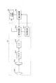
図1は、本発明の一実施形態に係る撮影装置10の構成を示す機能ブロック図である。また、図2は、撮影装置10に備えられた撮影部101の構成を示す機能ブロック図である。
図1は、本発明の一実施形態に係る撮影装置10の構成を示す機能ブロック図である。また、図2は、撮影装置10に備えられた撮影部101の構成を示す機能ブロック図である。
撮影装置10は、図1に示すように、前提構成として、図2に示す撮像素子101aを含む撮影部101と、該撮像素子101aの出力信号から生成された少なくとも1フレームの画像データを一時的に記憶することが可能なバッファ記憶部102(一時記憶部)とを備えている。
さらに、撮影装置10は、失敗条件判定手段および制御手段としての役割を担う撮影制御部103を備えている。
上記失敗条件判定手段としての撮影制御部103は、上記画像データが、予め設定された失敗条件を満たした失敗画像データであるかどうかを判定する。また、上記制御手段としての撮影制御部103は、上記のように判定された上記失敗画像データを破棄する。
これにより、撮像素子101aの出力信号から生成された1フレームの画像データが、失敗画像データであると、撮影制御部103によって判定された場合には、その失敗画像データが、撮影制御部103によって破棄される。
この結果、撮影画像を保存するために、バッファ記憶部102とは別に用意された撮影画像記憶部104には、ユーザの意図にかなった成功画像データのみが蓄積される。したがって、撮影画像記憶部104の記憶容量が、上記失敗画像データによって損失するという問題が生じない、言い換えれば、成功画像データのための記憶容量を増やすことができる。この結果、後述するように、連写可能時間を延ばすことができる。
(撮影部の構成)
撮影部101は、一例として、図2に示すように、上記撮像素子101aと、撮像光学系101b、プリアンプ101c、A/D変換器101d、信号処理部101eおよび動き検出部101fを備えている。ここでは、上記動き検出部101fを除いた撮影部101の構成と動作とについて以下説明する。
撮影部101は、一例として、図2に示すように、上記撮像素子101aと、撮像光学系101b、プリアンプ101c、A/D変換器101d、信号処理部101eおよび動き検出部101fを備えている。ここでは、上記動き検出部101fを除いた撮影部101の構成と動作とについて以下説明する。
被写体の光学像は、撮像光学系101bにより撮像素子101a上に結像し、電気信号に変換される。電気信号はプリアンプ101cで増幅された後、A/D変換器101dによってディジタル信号に変換される。
なお、撮像素子101aとして、CCD(Charge Coupled Device)またはCMOS(Complementary Metal Oxide Semiconductor)型素子などを採用することができる。
信号処理部101eは、A/D変換器101dから出力されるディジタル信号について、例えば1枚の静止画(フレーム画像)に相当する単位(1フレーム単位)で取り込みを行い、取り込んだ静止画単位のディジタル信号に所要の信号処理を施す。
こうして、1枚の静止画に相当する画像データが、信号処理部101eで生成され、上記バッファ記憶部102に一時的に保存される。なお、バッファ記憶部102は、連写によって取得された複数フレームの画像データを一時的に記憶することが可能な記憶容量を有していてもよい。
ユーザが、図1に示す入力部100を介して、連写モードの設定指示を撮影制御部103に与えると、信号処理部101eは、撮影制御部103からの指示に応じて、連写モードに応じた信号処理を行う。すなわち、信号処理部101eは、A/D変換器101dから、所定の時間間隔かつ1フレーム単位で、ディジタル信号を連続的に取りこんで信号処理を施すことによって、複数フレームの画像データを順次生成する。
また、撮影部101は、例えば1秒間に30フレームの一定のフレーム周期で、表示用の画像データを出力する。この表示用の画像データは、撮影制御部103から、後述する撮影画像表示制御部106へ送られ、電子ビューファインダ画面を備えた後述の撮影画像表示部105に、被写体の映像がリアルタイムで表示される。ユーザは、撮影画像表示部105に表示された被写体の映像を見ながら、シャッタチャンスを待つことができる。
なお、上述の所定の時間間隔、すなわち連写間隔(1秒間あたりの連写枚数)は、ユーザが、入力部100を介して増減させることができる。
信号処理部101eから出力される画像データは、バッファ記憶部102に一時的に保存され、後述する失敗条件判定処理の対象とされる。1フレームの画像データがバッファ記憶部102に保存される毎に失敗条件判定処理を実行する形態では、その画像データが失敗データである場合に、撮影制御部103は、その画像データを削除する制御を行えば済む。
しかし、このような形態に限定される必要はなく、連写によって生成された複数フレームの画像データをバッファ記憶部102に保存した後で、失敗条件判定処理を実行してもよい。
上記後者の形態では、複数フレームの画像データには、信号処理部101eによってそれぞれ識別子が付与され、画像データと識別子とが対応付けられた状態でバッファ記憶部102に一時的に記憶される。各画像データの識別子の情報は、信号処理部101eから撮影制御部103にも送られ、撮影制御部103に含まれたRAMなどに一時的に記憶される。
撮影制御部103は、連写によって生成された複数フレームの画像データの中に、失敗条件を満たす失敗画像データの有無を監視し、失敗画像データが発生すると、上記識別子によって失敗画像データを特定し、破棄(削除)する。
なお、撮影制御部103は、上記失敗画像データがバッファ記憶部102に記憶される前に、バッファ記憶部102に記憶されないような処理を行ってもよいし、上記失敗画像データがバッファ記憶部102または上記撮影画像記憶部104に記憶された後に、その失敗画像データを破棄してもよい。前者の処理は、後述する失敗条件判定の第2例(動き検出)において採用することができる。
(撮影画像の合成)
図1に示すように、撮影装置10は、連写によって取得された複数フレームの画像データを用いて合成画像データを作成する撮影画像合成部107を備えている。撮影画像合成部107は、バッファ記憶部102または撮影画像記憶部104から、失敗画像データを含まない複数の成功画像データを取得して、合成画像データを作成する。
図1に示すように、撮影装置10は、連写によって取得された複数フレームの画像データを用いて合成画像データを作成する撮影画像合成部107を備えている。撮影画像合成部107は、バッファ記憶部102または撮影画像記憶部104から、失敗画像データを含まない複数の成功画像データを取得して、合成画像データを作成する。
したがって、合成画像データの作成に、失敗画像データが使われることがないので、高品質で、ユーザの意図に即した合成画像データを得ることができる。
合成画像データの作成にあたって、ユーザは、上記画像データに対応した撮影画像を撮影装置10に表示させることができる。図1に示すように、撮影装置10は、液晶ディスプレイなどの前記撮影画像表示部105(表示部)と、撮影画像表示部105の表示動作を制御する前記撮影画像表示制御部106(表示制御手段)とをさらに備えている。
成功画像データに対応した撮影画像を、撮影画像表示部105に表示させる形態として、撮影画像表示制御部106が、各撮影画像のサムネイル画像を作成して、撮影画像表示部105に複数のサムネイル画像を表示させてもよい。また、撮影画像表示制御部106が、複数の撮影画像を縮小せずに1枚ずつ、所定の時間間隔で順番に切り換えて(いわゆるスライドショー形式で)表示させてもよい。
(連写モード時の表示例)
図4は、撮影装置10の表示画面における連写モード時の表示例を示す模式図である。画面例1では、連写による撮影回数、言い換えると、連写モードで撮影された失敗画像の枚数および成功画像の枚数を合計した総枚数(連写枚数)と、連写可能な残り枚数(残数)と、取得された成功画像の枚数(成功)と、発生した失敗画像の枚数(失敗)と、連写可能な残り時間(残り秒数)とが表示されている。これら5種類の表示内容は、連動して変化する。
図4は、撮影装置10の表示画面における連写モード時の表示例を示す模式図である。画面例1では、連写による撮影回数、言い換えると、連写モードで撮影された失敗画像の枚数および成功画像の枚数を合計した総枚数(連写枚数)と、連写可能な残り枚数(残数)と、取得された成功画像の枚数(成功)と、発生した失敗画像の枚数(失敗)と、連写可能な残り時間(残り秒数)とが表示されている。これら5種類の表示内容は、連動して変化する。
画面例2では、連写可能な残り枚数(連写残数)のみが表示されている。ただし、連写を開始してから経過した時間(連写時間)が、失敗画像が破棄された結果、連写の開始当初に求められた連写可能時間を超えて延長された場合に、連写残数の表示色が変わる(例えば、黒から赤へ)ようになっている。これにより、ユーザは、連写可能時間が延長されたことを認識することができる。
画面例3では、連写可能な残り時間をバー(灰色部分)の長さで表示するようになっている。バーの長さは、連写によって成功画像のみが取得されるときには、単調に減少するが、失敗画像が破棄されると、減少が止まるように表示される。なお、失敗画像が破棄されると、バーの長さが回復して増えるように表示させてもよいが、この場合には、バーの長さの揺らぎが煩わしく感じられる可能性がある。
また、画面例2で説明した表示色の変化を画面例3に適用し、連写時間が当初の連写可能時間を超えたときに、バーの表示色を変化させてもよい。さらに、画面例1~3の表示形態を適宜組み合わせてもよい。
(連写残数の表示に関わる構成)
上記画面例1または2のように、連写可能な残り枚数を表示するための構成について、以下説明する。
上記画面例1または2のように、連写可能な残り枚数を表示するための構成について、以下説明する。
図1に示すように、撮影装置10は、さらに、連写残数カウンタ108、失敗枚数カウンタ109、連写残数記憶部110、連写残数表示制御部111(表示制御手段)、連写残数表示部112(表示部)、撮影シャッタ判定部113、および連写枚数計数部114を備えている。
上記撮影制御部103は、連写モードが設定されると、連写可能な枚数を連写残数カウンタ108にセットする。この連写可能な枚数は、ユーザが入力部100を介して指定できるようになっている。しかし、これに限定されず、上記撮影画像記憶部104に保存される上記1フレームの画像データのサイズと、上記撮影画像記憶部104の空き容量とに基づいて、撮影制御部103が、上記サイズの画像データを上記撮影画像記憶部104に保存可能なフレーム枚数を算出するようにしてもよい。
また、撮影部101に含まれる図示しないシャッタが1回開閉する毎に、上記撮影シャッタ判定部113が、撮影の実行を認識し、撮影の実行を知らせる信号を撮影制御部103へ出力する。撮影制御部103は、撮影シャッタ判定部113から信号が入力されるのに応じて、連写残数カウンタ108および連写枚数計数部114へ信号を出力する。これにより、連写残数カウンタ108は、連写可能な枚数をカウントダウンすることができる。
これにより、連写残数カウンタ108は、ユーザによる連写中に、設定された連写可能な枚数まで、残り枚数が何枚かを示す情報、すなわち上記連写残数を出力し、連写残数記憶部110に記憶させる。
連写枚数計数部114は、ユーザの1回のシャッタ操作に対する一連の連写実行回数をカウントし、そのときのカウント値を保持する。
失敗枚数カウンタ109は、後述するように、撮影制御部103が失敗画像データを検出する毎に、失敗画像データの発生を知らせる信号を撮影制御部103から受け取る。こうして、失敗枚数カウンタ109は、失敗画像データのフレーム枚数をカウントする。
なお、連写残数カウンタ108は、撮影制御部103が失敗画像データを検出する毎に、その検出を示す信号を撮影制御部103から受け取ることによって、カウントアップされる、すなわち失敗フレーム枚数が加えられるようになっている。しかし、これに限られず、失敗枚数カウンタ109がカウントアップされる毎に、失敗枚数カウンタ109の出力によって連写残数カウンタ108がカウントアップされるようになっていてもよい。
このように、連写残数カウンタ108を備えたことによって、連写可能枚数に失敗画像の発生枚数が、ユーザによる連写中にリアルタイムで加算される。この結果、連写残数カウンタ108が出力するカウント値が、連写残数として連写残数記憶部110に記憶される。連写残数表示制御部111は、連写残数記憶部110に記憶された連写残数を読み出して、図4に例示したように連写残数表示部112に連写残数を表示させる。
これにより、ユーザは、常に、成功画像の連写可能枚数をリアルタイムで知ることができる。
なお、図1では、連写残数表示制御部111および連写残数表示部112を、撮影画像表示部105および撮影画像表示制御部106とは異なる機能ブロックで示しているが、実装構成としては、それぞれ、同一の表示制御部および同一の表示部であって構わない。
(連写時間の表示に関わる構成)
次に、上記画面例1または3のように、連写可能な残り時間(連写可能時間)を表示するための構成について説明する。
次に、上記画面例1または3のように、連写可能な残り時間(連写可能時間)を表示するための構成について説明する。
図1に示すように、撮影装置10は、さらに、連写時間算出部115と、連写時間延長通知表示制御部116と、連写時間延長通知表示部117とを備えている。
連写時間算出部115は、撮影制御部103とともに本発明に係る制御手段を構成している。また、連写時間算出部115は、上記連写残数カウンタ108のカウント値と、連写するときの1回の撮影に要する時間とに基づいて、連写可能時間を算出する。
例えば、撮影部101から、1秒あたり30フレームのフレーム周期(fps)で、画像データが出力されるとし、連写の撮影周期も1秒あたり30フレームであるとする。この場合、1回の撮影に要する時間は、1/30秒だから、連写可能時間は、次式で与えられる。
連写可能時間=連写残数×1/30秒
こうして、連写時間算出部115は、連写可能時間を算出し、連写時間延長通知表示制御部116へ出力する。そこで、図4の表示例によって説明したように、連写時間延長通知表示制御部116は、数字またはバーによって、連写可能時間を連写時間延長通知表示部117にリアルタイムで表示させる。
連写可能時間=連写残数×1/30秒
こうして、連写時間算出部115は、連写可能時間を算出し、連写時間延長通知表示制御部116へ出力する。そこで、図4の表示例によって説明したように、連写時間延長通知表示制御部116は、数字またはバーによって、連写可能時間を連写時間延長通知表示部117にリアルタイムで表示させる。
さらに、撮影制御部103は、連写開始時に求めた上記連写可能時間を当初連写可能時間(最大値を持つ連写可能時間)として、その時間経過を監視する。当初連写可能時間が経過したときに、上記連写可能時間が0になっていない場合、撮影制御部103は、上記当初連写可能時間の延長を連写時間延長通知表示部117に表示させるように、連写時間延長通知表示制御部116に指示する。
連写中における連写残数カウンタ108のカウント値が、失敗画像の発生数に応じて一時的に増加した場合、その増加に伴って、連写途中の連写可能時間は一時的に増加する。この結果、当初連写可能時間が経過しても、上記連写可能時間が0にならない状態が生じる。この状態は、当初連写可能時間が延長された状態である。したがって、当初連写可能時間が延長されたことを、前述した画面例2のような表示形態で、画面に表示させると、ユーザは、当初連写可能時間が延長されたことをリアルタイムで知ることができる。
なお、図1では、連写時間延長通知表示制御部116および連写時間延長通知表示部117を、撮影画像表示部105および撮影画像表示制御部106とは異なる機能ブロックで示しているが、実装構成としては、それぞれ、同一の表示制御部および同一の表示部であって構わない。
(失敗条件判定の構成と動作-第1例)
図1に示すように、撮影装置10は、さらに、特定画像識別部120(画像判定手段)および特定画像記憶部121を備えている。
図1に示すように、撮影装置10は、さらに、特定画像識別部120(画像判定手段)および特定画像記憶部121を備えている。
上記特定画像記憶部121には、ユーザが撮影を希望する特定の被写体の画像(特定画像)が、ユーザによって予め記憶(登録)されている。特定画像は、例えば、特定人物の顔画像、特定車種の自動車またはオートバイのような乗り物の画像、あるいは特定の動物の特徴をよく表す画像などである。
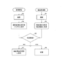
図5は、特定画像を用いた失敗画像の判定処理手順を示すフローチャートである。
例えば、ユーザが、サッカーの試合会場で、特定の選手が活躍する場面を、シャッタチャンスを逃すことなく撮影したい場合、その特定の選手を他の選手から区別し得るような、その特定の選手の特定部位を撮影する(ステップ1;以下、S1のように略記する)。特定部位は、正面または側面の顔であってもよいし、その特定の選手が着ているユニフォームにプリントされた背番号でもよいし、その特定の選手のみが身に着けている独特のカラーデザインのソックスなどであってもよい。
本実施形態では、特定部位の画像が顔画像であるとして、以下説明する。S1にて撮影された顔画像は、上記特定画像記憶部121に保存される(S2)。
特定の選手の動きを追跡するように連写が開始されると、撮影部101で複数フレームの画像データが順次生成される(S3)。生成された画像データは、前述したように、バッファ記憶部102に一時的に保存される(S4)。
続いて、特定画像識別部120は、バッファ記憶部102に保存された1フレームの画像データを読み出し、特定画像記憶部121に保存(登録)された顔画像(特定の被写体画像データ)が、各画像データに含まれているかいないかを判定する(S5)。登録された顔画像を含まない画像データは、失敗画像データであると判定され、登録された顔画像を含む画像データは、成功画像データであると判定される。
なお、S5の判定処理には、画像データから顔領域を抽出し、顔領域の特徴データと、登録された顔画像の特徴データとを照合するなどの公知の顔認証アルゴリズムを適用することができる。
特定画像識別部120は、失敗画像データを認識すると、そのことを撮影制御部103へ通知する。この通知に基づいて、撮影制御部103は、バッファ記憶部102に保存された失敗画像データの破棄(削除)を実行する(S6)。なお、特定画像識別部120は、失敗画像データを認識すると、その失敗画像データの前記識別子を撮影制御部103へ通知するようにしてもよい。
一方、撮影制御部103は、成功画像データを認識すると、そのことを撮影制御部103へ通知する。この通知に基づいて、撮影制御部103は、バッファ記憶部102に保存された成功画像データを撮影画像記憶部104へ出力する(S7)。あるいは、バッファ記憶部102に複数フレームの画像データを一時的に保存する形態では、失敗画像データがバッファ記憶部102から除かれた後、バッファ記憶部102に残された全ての画像データ(すなわち、成功画像データ)を撮影画像記憶部104へ移送するようにバッファ記憶部102を制御してもよい。この場合には、成功画像データは、識別子と対応付けされた状態で、撮影画像記憶部104に記憶される。
以上の処理によって、特定の選手の顔が撮影範囲から外れてしまった状態で撮影された画像が、失敗画像として特定され破棄される。したがって、シャッタチャンスを的確に捉えた成功画像のみをユーザは連写によって取得することができる。
また、失敗画像は、撮影装置10に保存されることがないので、撮影装置10の記憶容量が、失敗画像によってロスするということがない。この結果、連写可能枚数が多く確保されるので、シャッタチャンスを的確に捉えた成功画像を連写によって取得できる可能性を高めることができる。
さらに、上記撮影画像記憶部104には、連写によって得た成功画像データのみが蓄積されるため、その成功画像データを用いて、1枚の合成画像を作成する場合に、高品質の合成画像を作成したり、あるいは、ユーザの意図にかなった合成画像を作成することもできる。
(失敗条件判定の構成と動作-第2例)
失敗画像を特定して破棄する他の処理例(第2例)について、以下説明する。
失敗画像を特定して破棄する他の処理例(第2例)について、以下説明する。
第2例は、撮影範囲に侵入してきた不要なオブジェクトが撮影された画像を、失敗画像と判定する処理である。その処理には、図2に示す動き検出部101fが中心的な役割を担う。
連写が開始されると、撮影制御部103は、撮像素子101aの受光領域に配列された画素のうち、最も外側の画素を含む額縁状の周囲領域(動体検出領域)と、それ以外の撮影領域とに分け、撮影領域から出力された電気信号から生成された画像のみを撮影画像表示部105に表示させる。
動き検出部101fは、連写モードが選択されている場合、動体検出領域から出力された電気信号に基づいて信号処理部101eで生成されたフレーム単位のデータ(以下、このデータのことを額縁データと呼ぶ)を順次(場合によっては、識別子とともに)受け取る。さらに、動き検出部101fは、連続する2つのフレームの額縁データを比較することにより、額縁データの時間的変化の情報を撮影制御部103に送る。
撮影制御部103は、その時間的変化の情報を監視して、失敗画像が発生したかどうかを判定する。具体的には、動体検出領域の周囲で額縁データに大きな時間的変化が最初に現れ、その時間的変化が、動体検出領域の周囲から撮影領域の中央へ向かって伝播するかどうか(条件1)が監視される。さらに、時間的変化が、ある閾値と比較して大きいかどうか(条件2)が監視される。
上記の条件1および条件2がともにYESである場合に、撮影制御部103は、また、連続する2つのフレームのうち、時間的に後のフレームにおいて、不要なオブジェクトが侵入してきたと判定し、そのフレームの画像データを失敗画像データであると判定する。こうして、撮影制御部103は、失敗画像データのフレームを特定し、失敗画像データを破棄する。したがって、この第2例では、画像データをバッファ記憶部102に保存する前に、失敗画像データを特定し、破棄することができる。
なお、上記時間的変化が閾値より小さい場合には、撮影対象における微少な変化(例えば草木がざわめいている、遠くで人または車が動いている等)であるか、または撮影装置10の手振れであるなどと撮影制御部103は判断する。したがって、そのときのフレームの画像データは、成功画像データと判定され、バッファ記憶部102に保存される。
(成功枚数および失敗枚数の表示)
次に、連写による成功画像の枚数(成功枚数)および失敗画像の枚数(失敗枚数)を表示する構成と動作とについて、以下説明する。
次に、連写による成功画像の枚数(成功枚数)および失敗画像の枚数(失敗枚数)を表示する構成と動作とについて、以下説明する。
図1に示すように、撮影装置10は、さらに、撮影画像品質判定部131と、連写成功数表示制御部132(表示制御手段)と、連写成功数表示部133(表示部)と、連写失敗数表示制御部134(表示制御手段)と、連写失敗数表示部135(表示部)とをさらに備えている。
なお、図1では、連写成功数表示制御部132、連写成功数表示部133、連写失敗数表示制御部134および連写失敗数表示部135を、撮影画像表示部105および撮影画像表示制御部106とは異なる機能ブロックで示しているが、実装構成としては、それぞれ、同一の表示制御部および同一の表示部であって構わない。
(失敗枚数のリアルタイム表示)
初めに、成功枚数および失敗枚数を連写中にリアルタイムで表示する場合について説明する。
初めに、成功枚数および失敗枚数を連写中にリアルタイムで表示する場合について説明する。
前述したように、失敗枚数カウンタ109は、撮影制御部103が失敗画像データを検出する毎に、失敗画像データの発生を知らせる信号を撮影制御部103から受け取り、失敗画像データのフレーム枚数をカウントする。失敗枚数カウンタ109は、そのときの失敗カウント値のデータ(失敗数データ)を撮影制御部103に通知する。
続いて、撮影制御部103は、失敗枚数カウンタ109から失敗数データが送られると、その失敗数データを、失敗画像データの発生を知らせる信号とペアにして、撮影画像品質判定部131へ送る。
これにより、撮影画像品質判定部131は、撮影制御部103から受け取った失敗数データが失敗枚数であることを認識できるので、その失敗数データを連写失敗数表示制御部134へ送る。連写失敗数表示制御部134は、図4に画面例1として示すように、連写失敗数表示部135に失敗枚数をリアルタイムで表示させる。
(成功枚数のリアルタイム表示)
前述したように、連写枚数計数部114は、ユーザの1回のシャッタ操作に対する一連の連写実行回数をカウントし、そのときのカウント値を保持している。このカウント値は、連写枚数データとして撮影制御部103に送られる。したがって、撮影制御部103は、連写枚数データと失敗数データとを用いて、減算を実行することによって、成功枚数を求めることができる。
前述したように、連写枚数計数部114は、ユーザの1回のシャッタ操作に対する一連の連写実行回数をカウントし、そのときのカウント値を保持している。このカウント値は、連写枚数データとして撮影制御部103に送られる。したがって、撮影制御部103は、連写枚数データと失敗数データとを用いて、減算を実行することによって、成功枚数を求めることができる。
続いて、撮影制御部103は、求めた成功枚数を成功数データとして撮影画像品質判定部131へ送る。撮影画像品質判定部131は、失敗画像データの発生を知らせる信号とペアになっていない成功数データの入力を、失敗カウント値ではないと認識することができる。こうして、成功数データは、撮影画像品質判定部131から連写成功数表示制御部132へ送られ、連写成功数表示制御部132は、図4に画面例1として示すように、連写成功数表示部133に成功枚数をリアルタイムで表示させる。
なお、図4の画面例1のように、連写枚数と成功枚数とを併せてリアルタイムで表示する場合には、連写枚数データと成功数データとを区別する信号(またはデータ)とともに、撮影制御部103から撮影画像品質判定部131へ送ればよい。
(連写完了後のまとめ表示)
上記のように成功枚数および失敗枚数をリアルタイムで表示するのではなく、連写完了後に結果として表示するまとめ表示を行ってもよい。
上記のように成功枚数および失敗枚数をリアルタイムで表示するのではなく、連写完了後に結果として表示するまとめ表示を行ってもよい。
この場合、連写中には連写枚数、連写残数および残り秒数のみを表示し、連写完了後に、連写枚数、成功枚数および失敗枚数のみを表示するとよい。すなわち、予定された連写が完了し、連写残数および残り秒数がともに0になった場合には、連写残数および残り秒数を表示しないようにする。もちろん、連写残数を0、残り秒数を0として表示しても構わない。
上記のように、成功枚数および失敗枚数を連写完了後に、結果として表示する場合、撮影制御部103は、ユーザのシャッタ操作を示す信号が検知されなくなったときに、失敗枚数カウンタ109に、そのときの失敗カウント値のデータを出力させる。この後、撮影制御部103は、リアルタイムに把握していた連写枚数から失敗枚数を減算して成功枚数を求め、連写枚数、失敗枚数および成功枚数を区別する信号(またはデータ)とともに、撮影画像品質判定部131へ送る。
(連写モードにおける一連の制御手順)
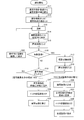
最後に、図3を参照しながら、連写モードにおける一連の制御手順を整理して説明する。図3は、連写モードにおける一連の制御手順を示すフローチャートである。
最後に、図3を参照しながら、連写モードにおける一連の制御手順を整理して説明する。図3は、連写モードにおける一連の制御手順を示すフローチャートである。
ユーザが、入力部100から連写モードの設定を撮影制御部103に指示する。これにより、撮影装置10は、通常撮影モードから連写モードへ移行する。
連写モードでは、撮影制御部103は、まず連写枚数計数部114から連写可能枚数の値を読み込み(S11)、連写残数カウンタ108に連写可能枚数の値をセットする(S12)。この連写可能枚数は、連写残数カウンタ108から連写残数記憶部110を経て、連写残数表示制御部111から連写残数表示部112へと通知されるので、表示画面には、連写可能枚数が連写残数の最大値として表示される。
次に、ユーザがシャッタボタンを押すことにより、連写がスタートする(S13)。撮影部101から出力される画像データは、撮影制御部103からバッファ記憶部102へ送られ、そこに記憶される(S14)。
撮影部101のシャッタが1回開閉する毎に、撮影シャッタ判定部113から撮影制御部103へ、撮影が1回実行されたことを知らせる信号が出力される。撮影制御部103は、撮影シャッタ判定部113から信号が入力されるのに応じて、連写残数カウンタ108へ信号を出力する。これにより、連写残数カウンタ108は、連写可能枚数を1回分カウントダウンする(S15)。
続いて、撮影制御部103は、特定画像識別部120から特定画像の有無に関する判定結果、または動き検出部101fから額縁データの時間的変化の情報を受け取り、バッファ記憶部102にある画像データが失敗画像データかどうかを判定する(S16)。なお、S16の処理は、本発明に係る撮影制御方法において、撮影して取得された画像データが、予め設定された失敗条件を満たした失敗画像データであるかどうかを判定する第1ステップに相当する。
バッファ記憶部102にある画像データが失敗画像データの場合、すなわち、S16の判定結果がYESの場合、撮影制御部103は、バッファ記憶部102にある画像データを破棄する(S17)。その上で、撮影制御部103は、連写残数カウンタ108へ、失敗画像データの発生を知らせる信号を送り、連写残数カウンタ108を1回分カウントアップさせる(S18)。なお、連写残数カウンタ108のカウントアップを失敗枚数カウンタ109の出力によって行ってもよい。
なお、上記S17の処理は、本発明に係る撮影制御方法において、上記第1ステップにて判定された上記失敗画像データを破棄する第2ステップに相当する。
S16の判定結果がNOの場合、またはS18が実行された場合、処理はS19へ進む。S19では、連写残数カウンタ108の値が0かどうかを撮影制御部103が判断する。連写残数カウンタ108の値が0ではなければ、処理がS20へ進む。S20では、連写枚数、連写残数、成功枚数、失敗枚数および残り秒数の全てを連携させて、あるいは適宜に選択した組み合わせを連携させて、表示部に表示する。その後、処理はS20からS13へ戻る。
処理がS20からS13へ戻る結果、S14では、複数フレームの成功画像データが、バッファ記憶部102に蓄積される。しかし、このような形態に限らず、S16に続けて後述するS21を実行し、1フレームの成功画像データが、逐次、撮影画記憶部104に移動するようにしてもよい。こうすれば、バッファ記憶部102の記憶容量が1フレーム分程度に小さくて済む。
S19で、連写残数カウンタ108の値が0であることを撮影制御部103が検知すると、続いて、連写画像を表示部に表示する処理および合成画像を作成する処理のいずれか一方、あるいは両方が、ユーザの指示に基づいて、あるいは自動的に実行される。
連写画像を表示部に表示する処理が実行される場合、撮影制御部103は、バッファ記憶部102に保存中の全フレームの画像データを撮影画像記憶部104へコピーし(S21)、バッファ記憶部102に保存された画像データをクリアする(S22)。
最後に、撮影制御部103は、連写画像を撮影画像表示部105に表示するように撮影画像表示制御部106に指示する結果、連写画像が撮影画像表示部105に表示され(S23)、全ての処理が終了する。
一方、合成画像を作成する処理が実行される場合、撮影制御部103は、バッファ記憶部102に保存中の全フレームの画像データを撮影画像合成部107に出力させ、撮影画像合成部107に合成画像を作成させる(S24)。作成された合成画像は、撮影画像記憶部104に保存される(S25)。続いて、撮影制御部103は、バッファ記憶部102に保存された画像データをクリアする(S26)。なお、このS26の処理は、S25の処理の前で実行してもよい。
最後に、撮影制御部103は、合成画像を撮影画像表示部105に表示するように撮影画像表示制御部106に指示する結果、合成画像が撮影画像表示部105に表示され(S27)、全ての処理が終了する。
なお、本発明の撮影装置を以下のように構成してもよい。
(構成1)
連続して撮影することで複数の撮影画像を記憶する撮影装置において、
前記撮影画像が失敗画像か否か判定する撮影画像品質判定部を備え、
前記撮影画像が失敗画像であれば破棄することを特徴とする撮影装置。
連続して撮影することで複数の撮影画像を記憶する撮影装置において、
前記撮影画像が失敗画像か否か判定する撮影画像品質判定部を備え、
前記撮影画像が失敗画像であれば破棄することを特徴とする撮影装置。
(構成2)
連写枚数の残数をカウントする連写残数カウンタを備え、
前記失敗画像の枚数と同数を前記連写残数カウンタに加えることを特徴とする構成1に記載の撮影装置。
連写枚数の残数をカウントする連写残数カウンタを備え、
前記失敗画像の枚数と同数を前記連写残数カウンタに加えることを特徴とする構成1に記載の撮影装置。
(構成3)
当初の連写完了時間を超えた場合に表示部にその旨を通知することを特徴とする構成2に記載の撮影装置。
当初の連写完了時間を超えた場合に表示部にその旨を通知することを特徴とする構成2に記載の撮影装置。
(構成4)
あらかじめ登録された顔画像と、前記撮影画像に前記顔画像が含まれるか否か判定する顔画像識別部とを備え、
前記撮影画像品質判定部は前記顔画像識別部によって前記撮影画像に前記顔画像が含まれていないと判定された前記撮影画像を前記失敗画像と判定することを特徴とする構成1に記載の撮影装置。
あらかじめ登録された顔画像と、前記撮影画像に前記顔画像が含まれるか否か判定する顔画像識別部とを備え、
前記撮影画像品質判定部は前記顔画像識別部によって前記撮影画像に前記顔画像が含まれていないと判定された前記撮影画像を前記失敗画像と判定することを特徴とする構成1に記載の撮影装置。
(構成5)
前記撮影画像を表示する撮影画像表示部を備え、
連続しての撮影完了後に、前記撮影画像表示部は前記撮影画像を表示することを特徴とする構成1に記載の撮影装置。
前記撮影画像を表示する撮影画像表示部を備え、
連続しての撮影完了後に、前記撮影画像表示部は前記撮影画像を表示することを特徴とする構成1に記載の撮影装置。
(構成6)
前記複数の撮影画像を合成し高品質な画像を作成する撮影画像合成部を備え、
連続しての撮影完了後に前記撮影画像表示部は前記合成画像を表示することを特徴とする構成1に記載の撮影装置。
前記複数の撮影画像を合成し高品質な画像を作成する撮影画像合成部を備え、
連続しての撮影完了後に前記撮影画像表示部は前記合成画像を表示することを特徴とする構成1に記載の撮影装置。
(ソフトウェアによる実現例)
最後に、撮影装置10を構成する各部103,106,107,111,113,114,115,116,120,131,132,134は、集積回路(ICチップ)上に形成された論理回路によってハードウェア的に実現してもよいし、CPU(Central Processing Unit)を用いてソフトウェア的に実現してもよい。
最後に、撮影装置10を構成する各部103,106,107,111,113,114,115,116,120,131,132,134は、集積回路(ICチップ)上に形成された論理回路によってハードウェア的に実現してもよいし、CPU(Central Processing Unit)を用いてソフトウェア的に実現してもよい。
後者の場合、撮影装置10は、各機能を実現する撮影制御プログラムの命令を実行するCPU、上記プログラムを格納したROM(Read Only Memory)、上記プログラムを展開するRAM(Random Access Memory)、上記プログラムおよび各種データを格納するメモリ(コンピュータ読取可能な記録媒体)などを備えている。
そして、本発明の目的は、上述した機能を実現するソフトウェアである撮影制御プログラムのプログラムコード(実行形式プログラム、中間コードプログラム、ソースプログラム)をコンピュータで読み取り可能に記録した記録媒体を、上記撮影装置10に供給し、そのコンピュータ(またはCPUやMPU)が記録媒体に記録されているプログラムコードを読み出し実行することによっても、達成可能である。
上記記録媒体としては、例えば、磁気テープやカセットテープ等のテープ類、フロッピー(登録商標)ディスク/ハードディスク等の磁気ディスクやCD-ROM/MO/MD/DVD/CD-R等の光ディスクを含むディスク類、ICカード(メモリカードを含む)/光カード等のカード類、マスクROM/EPROM/EEPROM/フラッシュROM等の半導体メモリ類、あるいはPLD(Programmable logic device)やFPGA(Field Programmable Gate Array)等の論理回路類などを用いることができる。
また、撮影装置10を通信ネットワークと接続可能に構成し、上記プログラムコードを通信ネットワークを介して供給してもよい。この通信ネットワークは、プログラムコードを伝送可能であればよく、特に限定されない。例えば、インターネット、イントラネット、エキストラネット、LAN、ISDN、VAN、CATV通信網、仮想専用網(Virtual Private Network)、電話回線網、移動体通信網、衛星通信網等が利用可能である。
また、この通信ネットワークを構成する伝送媒体も、プログラムコードを伝送可能な媒体であればよく、特定の構成または種類のものに限定されない。例えば、IEEE1394、USB、電力線搬送、ケーブルTV回線、電話線、ADSL(Asymmetric Digital Subscriber Line)回線等の有線でも、IrDAやリモコンのような赤外線、Bluetooth(登録商標)、IEEE802.11無線、HDR(High Data Rate)、NFC(Near Field Communication)、DLNA(Digital Living Network Alliance)、携帯電話網、衛星回線、地上波デジタル網等の無線でも利用可能である。
なお、本発明は、上記プログラムコードが電子的な伝送で具現化された、搬送波に埋め込まれたコンピュータデータ信号の形態でも実現され得る。
本発明に係る撮影装置では、上記失敗条件判定手段は、連写によって、上記撮像素子の出力信号から生成された複数フレームの画像データのそれぞれについて、上記失敗画像データであるかどうかを判定することを特徴とする。
上記の構成によれば、連写によって複数フレームの画像データを連続取得した場合に、前述したように、上記画像記憶部の記憶容量が、失敗画像データによって損失するという問題が生じない。連写可能な撮影枚数は、上記画像記憶部の記憶容量の空き容量(残容量)に依存するから、失敗画像データを破棄する結果、上記残容量が増え、連写可能な撮影枚数を従来より多く確保することができる。
この結果、シャッターチャンスを従来より逃がしにくい連写機能を備えた撮影装置を提供することができる。
また、上記画像記憶部には、連写によって得た成功画像データのみが蓄積されるため、その成功画像データを用いて、1枚の合成画像を作成する場合に、高品質の合成画像を作成したり、あるいは、ユーザの意図にかなった合成画像を作成することができる。
なお、上記一時記憶部は、連写によって取得された複数フレームの画像データを一時的に記憶することが可能な記憶容量を有していてもよいし、1フレーム分の画像データを一時的に記憶することが可能な記憶容量を有していてもよい。後者の場合には、失敗画像かどうかの判定が完了した1フレームの画像データは、失敗画像であれば、一時記憶部から削除され、成功画像であれば、画像記憶部に出力され保存される。
本発明に係る撮影装置は、
(1)連写開始時にセットされた連写可能なフレーム枚数を、連写による撮影の実行毎にカウントダウンする連写残数カウンタをさらに備え、
(2)上記制御手段は、上記失敗画像データの発生回数分、上記連写残数カウンタをカウントアップさせることを特徴とする。
(1)連写開始時にセットされた連写可能なフレーム枚数を、連写による撮影の実行毎にカウントダウンする連写残数カウンタをさらに備え、
(2)上記制御手段は、上記失敗画像データの発生回数分、上記連写残数カウンタをカウントアップさせることを特徴とする。
上記の構成によれば、連写残数カウンタを備えたことによって、連写可能枚数に、失敗画像の発生枚数が加算される。この結果、連写残数カウンタのカウント値に基づいて、ユーザに対し、常に、成功画像の連写可能枚数を知らせるように撮影装置を構成することができる。
本発明に係る撮影装置は、
(1)撮影に関する情報を表示する表示部と、
(2)上記表示部の表示動作を制御する表示制御手段とをさらに備え、
(3)上記制御手段は、上記連写残数カウンタのカウント値と、連写するときの1回の撮影に要する時間とに基づいて、連写可能時間を算出し、
(4)連写開始時に求めた上記連写可能時間を当初連写可能時間として、その時間経過を監視し、
(5)当初連写可能時間が経過したときに、上記連写可能時間が0になっていない場合、上記当初連写可能時間の延長を上記表示部に表示させるように、上記表示制御手段に指示することを特徴とする。
(1)撮影に関する情報を表示する表示部と、
(2)上記表示部の表示動作を制御する表示制御手段とをさらに備え、
(3)上記制御手段は、上記連写残数カウンタのカウント値と、連写するときの1回の撮影に要する時間とに基づいて、連写可能時間を算出し、
(4)連写開始時に求めた上記連写可能時間を当初連写可能時間として、その時間経過を監視し、
(5)当初連写可能時間が経過したときに、上記連写可能時間が0になっていない場合、上記当初連写可能時間の延長を上記表示部に表示させるように、上記表示制御手段に指示することを特徴とする。
上記の構成によれば、制御手段は、例えば、連写残数カウンタのカウント値と連写するときの1回の撮影に要する時間とを乗算することによって、成功画像の連写可能時間を求める。この連写可能時間は、連写の開始時に最大値を持つ。最大値を持つ連写可能時間を上記のように当初連写可能時間と呼ぶ。
連写中における連写残数カウンタのカウント値が、失敗画像の発生数に応じて一時的に増加した場合、その増加に伴って、連写途中の連写可能時間は一時的に増加する。この結果、当初連写可能時間が経過しても、上記連写可能時間が0にならない状態が生じる。この状態は、当初連写可能時間が延長された状態である。したがって、当初連写可能時間が延長されたことを何らかの形態で、表示部に表示させると、ユーザは、当初連写可能時間が延長されたことを知ることができる。
本発明に係る撮影装置は、
(1)撮影に関する情報を表示する表示部と、
(2)上記表示部の表示動作を制御する表示制御手段とをさらに備え、
(3)上記制御手段は、上記連写残数カウンタのカウント値と、連写するときの1回の撮影に要する時間とに基づいて、連写可能時間を算出し、連写中にも、算出した連写可能時間を上記表示部に表示させるように、上記表示制御手段に指示することを特徴とする。
(1)撮影に関する情報を表示する表示部と、
(2)上記表示部の表示動作を制御する表示制御手段とをさらに備え、
(3)上記制御手段は、上記連写残数カウンタのカウント値と、連写するときの1回の撮影に要する時間とに基づいて、連写可能時間を算出し、連写中にも、算出した連写可能時間を上記表示部に表示させるように、上記表示制御手段に指示することを特徴とする。
上記の構成によれば、制御手段は、例えば、連写残数カウンタのカウント値と連写するときの1回の撮影に要する時間とを乗算することによって、成功画像の連写可能時間を求める。この連写可能時間は、連写中における連写残数カウンタのカウント値が、失敗画像の発生数に応じて一時的に増加した場合、その増加に伴って、一時的に増加する。
この結果、表示部は、失敗画像の発生毎に、成功画像の連写可能時間が一時的に増えるように、あるいは減少が止まるように、更新して表示することができる。
本発明に係る撮影装置は、
(1)上記撮影装置に予め記憶された特定の被写体画像データが、上記画像データに含まれているかどうかを判定する画像判定手段をさらに備え、
(2)上記失敗条件判定手段は、上記画像判定手段によって、上記被写体画像データが含まれていないと判定された上記画像データを、上記失敗画像データであると判定することを特徴とする。
(1)上記撮影装置に予め記憶された特定の被写体画像データが、上記画像データに含まれているかどうかを判定する画像判定手段をさらに備え、
(2)上記失敗条件判定手段は、上記画像判定手段によって、上記被写体画像データが含まれていないと判定された上記画像データを、上記失敗画像データであると判定することを特徴とする。
上記の構成によれば、ユーザは、通常、連写によって特定の被写体(人物、乗り物、動物など)の動きを追跡するように撮影することが多い。この場合、ユーザが撮影装置を特定の被写体の動きに合わせて動かすことになる。そうすると、撮影装置の動きと、特定の被写体の動きとが合わない場合に、特定の被写体が撮影範囲から外れてしまうと、失敗画像が発生する。すなわち、失敗画像の発生頻度は、通常撮影時より連写時に高くなる。
そこで、上記画像判定手段を設けることによって、連写時の失敗画像を特定しやすくなる。
本発明に係る撮影装置において、上記特定の被写体画像データは、特定の人物の顔画像データであることを特徴とする。
上記の構成によれば、上述したとおり、連写時の失敗画像を特定しやすくなるという効果を奏する上に、特定の人物を被写体とする連写に適した撮影装置を提供できるという効果を奏する。
本発明に係る撮影装置は、
(1)上記画像データに対応した撮影画像を表示する表示部と、
(2)上記表示部の表示動作を制御する表示制御手段とをさらに備え、
(3)上記表示制御手段は、上記連写の完了後に、連写によって取得された複数フレームの画像データから上記失敗画像データを除いた成功画像データに対応した撮影画像を、上記表示部に表示させることを特徴とする。
(1)上記画像データに対応した撮影画像を表示する表示部と、
(2)上記表示部の表示動作を制御する表示制御手段とをさらに備え、
(3)上記表示制御手段は、上記連写の完了後に、連写によって取得された複数フレームの画像データから上記失敗画像データを除いた成功画像データに対応した撮影画像を、上記表示部に表示させることを特徴とする。
上記の構成によれば、連写の完了後に表示部に表示される撮影画像には失敗画像が含まれていない。この結果、ユーザにとって、利用価値の高い連写機能を備えた撮影装置を提供することができる。
なお、成功画像データに対応した撮影画像を、上記表示部に表示させる形態として、撮影画像が、複数の画像によって構成されている場合、各撮影画像のサムネイル画像を作成して、表示部に複数のサムネイル画像を表示させてもよいし、複数の撮影画像を縮小せずに1枚ずつ、所定の時間間隔で順番に切り換えて表示させてもよい。
上記いずれかの撮影装置が備えた上記各手段(失敗条件判定手段、制御手段、表示制御手段および画像判定手段)として、コンピュータを機能させる撮影制御プログラムと、上記撮影制御方法の各ステップをコンピュータに実行させるための撮影制御プログラムと、その撮影制御プログラムを記録したコンピュータ読取可能な記録媒体も、本発明の範疇に含まれる。
本発明は上述した実施形態に限定されるものではなく、請求項に示した範囲で種々の変更が可能であり、開示された技術的手段を適宜組み合わせて得られる実施形態についても本発明の技術的範囲に含まれる。
本発明は、被写体を連写する機能を備えた撮影装置としての電子機器全般に適用することができる。
10 撮影装置
101a 撮像素子
102 バッファ記憶部(一時記憶部)
103 撮影制御部(失敗条件判定手段および制御手段)
104 画像記憶部
105 撮影画像表示部(表示部)
106 撮影画像表示制御部(表示制御手段)
108 連写残数カウンタ
111 連写残数表示制御部(表示制御手段)
112 連写残数表示部(表示部)
115 連写時間算出部(制御手段)
120 特定画像識別部(画像判定手段)
132 連写成功数表示制御部(表示制御手段)
133 連写成功数表示部(表示部)
134 連写失敗数表示制御部(表示制御手段)
135 連写失敗数表示部(表示部)
101a 撮像素子
102 バッファ記憶部(一時記憶部)
103 撮影制御部(失敗条件判定手段および制御手段)
104 画像記憶部
105 撮影画像表示部(表示部)
106 撮影画像表示制御部(表示制御手段)
108 連写残数カウンタ
111 連写残数表示制御部(表示制御手段)
112 連写残数表示部(表示部)
115 連写時間算出部(制御手段)
120 特定画像識別部(画像判定手段)
132 連写成功数表示制御部(表示制御手段)
133 連写成功数表示部(表示部)
134 連写失敗数表示制御部(表示制御手段)
135 連写失敗数表示部(表示部)
Claims (12)
- 撮像素子と、当該撮像素子の出力信号から生成された少なくとも1フレームの画像データを一時的に記憶することが可能な一時記憶部とを備えた撮影装置において、
上記画像データが、予め設定された失敗条件を満たした失敗画像データであるかどうかを判定する失敗条件判定手段と、
上記失敗条件判定手段によって判定された上記失敗画像データを破棄する制御手段とを備えていること
を特徴とする撮影装置。 - 上記失敗条件判定手段は、連写によって、上記撮像素子の出力信号から生成された複数フレームの画像データのそれぞれについて、上記失敗画像データであるかどうかを判定すること
を特徴とする請求項1に記載の撮影装置。 - 連写開始時にセットされた連写可能なフレーム枚数を、連写による撮影の実行毎にカウントダウンする連写残数カウンタをさらに備え、
上記制御手段は、上記失敗画像データの発生回数分、上記連写残数カウンタをカウントアップさせること
を特徴とする請求項2に記載の撮影装置。 - 撮影に関する情報を表示する表示部と、
上記表示部の表示動作を制御する表示制御手段とをさらに備え、
上記制御手段は、
上記連写残数カウンタのカウント値と、連写するときの1回の撮影に要する時間とに基づいて、連写可能時間を算出し、
連写開始時に求めた上記連写可能時間を当初連写可能時間として、その時間経過を監視し、
当初連写可能時間が経過したときに、上記連写可能時間が0になっていない場合、上記当初連写可能時間の延長を上記表示部に表示させるように、上記表示制御手段に指示すること
を特徴とする請求項3に記載の撮影装置。 - 撮影に関する情報を表示する表示部と、
上記表示部の表示動作を制御する表示制御手段とをさらに備え、
上記制御手段は、上記連写残数カウンタのカウント値と、連写するときの1回の撮影に要する時間とに基づいて、連写可能時間を算出し、連写中にも、算出した連写可能時間を上記表示部に表示させるように、上記表示制御手段に指示すること
を特徴とする請求項3に記載の撮影装置。 - 上記撮影装置に予め記憶された特定の被写体画像データが、上記画像データに含まれているかどうかを判定する画像判定手段をさらに備え、
上記失敗条件判定手段は、上記画像判定手段によって、上記被写体画像データが含まれていないと判定された上記画像データを、上記失敗画像データであると判定すること
を特徴とする請求項1から5のいずれか1項に記載の撮影装置。 - 上記特定の被写体画像データは、特定の人物の顔画像データであること
を特徴とする請求項6に記載の撮影装置。 - 上記画像データに対応した撮影画像を表示する表示部と、
上記表示部の表示動作を制御する表示制御手段とをさらに備え、
上記表示制御手段は、上記連写の完了後に、連写によって取得された複数フレームの画像データから上記失敗画像データを除いた成功画像データに対応した撮影画像を、上記表示部に表示させること
特徴とする請求項2から5のいずれか1項に記載の撮影装置。 - 撮影して取得された画像データが、予め設定された失敗条件を満たした失敗画像データであるかどうかを判定する第1ステップと、
上記第1ステップにて判定された上記失敗画像データを破棄する第2ステップとを備えていること
を特徴とする撮影制御方法。 - 請求項1から8のいずれか1項に記載の撮影装置が備えた上記各手段として、コンピュータを機能させるための撮影制御プログラム。
- 請求項9に記載の撮影制御方法の各ステップをコンピュータに実行させるための撮影制御プログラム。
- 請求項10または11に記載の撮影制御プログラムを記録したコンピュータ読取可能な記録媒体。
Applications Claiming Priority (2)
| Application Number | Priority Date | Filing Date | Title |
|---|---|---|---|
| JP2011-106313 | 2011-05-11 | ||
| JP2011106313 | 2011-05-11 |
Publications (1)
| Publication Number | Publication Date |
|---|---|
| WO2012153823A1 true WO2012153823A1 (ja) | 2012-11-15 |
Family
ID=47139298
Family Applications (1)
| Application Number | Title | Priority Date | Filing Date |
|---|---|---|---|
| PCT/JP2012/062069 Ceased WO2012153823A1 (ja) | 2011-05-11 | 2012-05-10 | 撮影装置、撮影制御方法、撮影制御プログラムおよびコンピュータ読取可能記録媒体 |
Country Status (1)
| Country | Link |
|---|---|
| WO (1) | WO2012153823A1 (ja) |
Cited By (2)
| Publication number | Priority date | Publication date | Assignee | Title |
|---|---|---|---|---|
| JP2016133356A (ja) * | 2015-01-16 | 2016-07-25 | 東京電力ホールディングス株式会社 | 弛度シミュレータおよびコンピュータプログラム |
| WO2018193698A1 (ja) * | 2017-04-18 | 2018-10-25 | ソニー株式会社 | 表示制御装置、撮像装置及び表示制御方法 |
Citations (4)
| Publication number | Priority date | Publication date | Assignee | Title |
|---|---|---|---|---|
| JP2005045600A (ja) * | 2003-07-23 | 2005-02-17 | Casio Comput Co Ltd | 画像撮影装置およびプログラム |
| JP2005136655A (ja) * | 2003-10-30 | 2005-05-26 | Canon Inc | カメラ |
| JP2008061107A (ja) * | 2006-09-01 | 2008-03-13 | Sega Corp | 自動写真館 |
| JP2008236149A (ja) * | 2007-03-19 | 2008-10-02 | Nikon Corp | カメラ |
-
2012
- 2012-05-10 WO PCT/JP2012/062069 patent/WO2012153823A1/ja not_active Ceased
Patent Citations (4)
| Publication number | Priority date | Publication date | Assignee | Title |
|---|---|---|---|---|
| JP2005045600A (ja) * | 2003-07-23 | 2005-02-17 | Casio Comput Co Ltd | 画像撮影装置およびプログラム |
| JP2005136655A (ja) * | 2003-10-30 | 2005-05-26 | Canon Inc | カメラ |
| JP2008061107A (ja) * | 2006-09-01 | 2008-03-13 | Sega Corp | 自動写真館 |
| JP2008236149A (ja) * | 2007-03-19 | 2008-10-02 | Nikon Corp | カメラ |
Cited By (5)
| Publication number | Priority date | Publication date | Assignee | Title |
|---|---|---|---|---|
| JP2016133356A (ja) * | 2015-01-16 | 2016-07-25 | 東京電力ホールディングス株式会社 | 弛度シミュレータおよびコンピュータプログラム |
| WO2018193698A1 (ja) * | 2017-04-18 | 2018-10-25 | ソニー株式会社 | 表示制御装置、撮像装置及び表示制御方法 |
| JPWO2018193698A1 (ja) * | 2017-04-18 | 2020-02-27 | ソニー株式会社 | 表示制御装置、撮像装置及び表示制御方法 |
| US11283990B2 (en) | 2017-04-18 | 2022-03-22 | Sony Corporation | Display control device, imaging device, and display control method |
| JP7215414B2 (ja) | 2017-04-18 | 2023-01-31 | ソニーグループ株式会社 | 表示制御装置、撮像装置及び表示制御方法 |
Similar Documents
| Publication | Publication Date | Title |
|---|---|---|
| JP4324170B2 (ja) | 撮像装置およびディスプレイの制御方法 | |
| CN106575027B (zh) | 摄像装置及其被摄体跟踪方法 | |
| CN101682691B (zh) | 图像处理装置及图像处理方法 | |
| TWI420898B (zh) | 攝影裝置、攝影方法及記錄有程式之電腦可讀取的記錄媒體 | |
| CN104883480B (zh) | 摄像装置和摄像方法 | |
| CN101621617A (zh) | 摄像装置和存储介质 | |
| CN102625036A (zh) | 图像处理装置、摄像装置及记录介质 | |
| JP5126207B2 (ja) | 撮像装置 | |
| US9413940B2 (en) | Digital electronic apparatus and method of controlling continuous photographing thereof | |
| JP5434038B2 (ja) | 撮像装置 | |
| JP5338373B2 (ja) | 撮像装置 | |
| JP2013110754A (ja) | カメラ装置、及びその撮影方法とプログラム | |
| WO2012153823A1 (ja) | 撮影装置、撮影制御方法、撮影制御プログラムおよびコンピュータ読取可能記録媒体 | |
| KR101062582B1 (ko) | 카메라의 이미지 캡쳐 방법, 카메라용 모듈, 카메라 및 이동 전화기 | |
| JP2010193324A (ja) | カメラ装置、及びその撮影方法とプログラム | |
| JPWO2007145032A1 (ja) | 画像処理回路、携帯端末およびセンサ制御方法 | |
| JP6232750B2 (ja) | 撮像装置 | |
| JP4278429B2 (ja) | 撮像装置 | |
| JP2010171848A (ja) | 撮像装置、撮像装置の制御方法および制御プログラム | |
| JP5383361B2 (ja) | 撮像装置及びその制御方法、並びにプログラム | |
| JP2011018989A (ja) | 撮像装置、画像選択方法、及び、プログラム | |
| JP5257124B2 (ja) | デジタルカメラおよび画像処理プログラム | |
| JP6702465B2 (ja) | 撮像装置 | |
| JP2007208355A (ja) | 撮影装置および方法並びにプログラム | |
| KR101247320B1 (ko) | 촬상 장치 |
Legal Events
| Date | Code | Title | Description |
|---|---|---|---|
| 121 | Ep: the epo has been informed by wipo that ep was designated in this application |
Ref document number: 12781567 Country of ref document: EP Kind code of ref document: A1 |
|
| NENP | Non-entry into the national phase |
Ref country code: DE |
|
| 122 | Ep: pct application non-entry in european phase |
Ref document number: 12781567 Country of ref document: EP Kind code of ref document: A1 |
|
| NENP | Non-entry into the national phase |
Ref country code: JP |