WO2012153812A1 - Co2回収装置およびco2回収方法 - Google Patents
Co2回収装置およびco2回収方法 Download PDFInfo
- Publication number
- WO2012153812A1 WO2012153812A1 PCT/JP2012/062035 JP2012062035W WO2012153812A1 WO 2012153812 A1 WO2012153812 A1 WO 2012153812A1 JP 2012062035 W JP2012062035 W JP 2012062035W WO 2012153812 A1 WO2012153812 A1 WO 2012153812A1
- Authority
- WO
- WIPO (PCT)
- Prior art keywords
- liquid
- gas
- absorption
- absorbing
- water
- Prior art date
Links
- 238000011084 recovery Methods 0.000 title claims abstract description 54
- 238000000034 method Methods 0.000 title claims description 14
- 239000007788 liquid Substances 0.000 claims abstract description 126
- XLYOFNOQVPJJNP-UHFFFAOYSA-N water Substances O XLYOFNOQVPJJNP-UHFFFAOYSA-N 0.000 claims abstract description 79
- 238000010521 absorption reaction Methods 0.000 claims abstract description 66
- 238000005406 washing Methods 0.000 claims abstract description 62
- 238000000926 separation method Methods 0.000 claims abstract description 25
- 238000000605 extraction Methods 0.000 claims abstract description 16
- 239000012141 concentrate Substances 0.000 claims abstract description 6
- 230000002745 absorbent Effects 0.000 claims description 34
- 239000002250 absorbent Substances 0.000 claims description 34
- 239000002253 acid Substances 0.000 claims description 23
- 238000011069 regeneration method Methods 0.000 claims description 23
- 230000008929 regeneration Effects 0.000 claims description 22
- 239000003513 alkali Substances 0.000 claims description 19
- 239000006096 absorbing agent Substances 0.000 claims description 14
- 238000004140 cleaning Methods 0.000 claims description 13
- 238000001816 cooling Methods 0.000 claims description 6
- 230000001172 regenerating effect Effects 0.000 claims description 2
- 239000000284 extract Substances 0.000 abstract description 2
- 239000012530 fluid Substances 0.000 abstract 10
- 239000007789 gas Substances 0.000 description 106
- 239000000243 solution Substances 0.000 description 60
- 238000010586 diagram Methods 0.000 description 12
- QGZKDVFQNNGYKY-UHFFFAOYSA-N Ammonia Chemical compound N QGZKDVFQNNGYKY-UHFFFAOYSA-N 0.000 description 11
- -1 amine compounds Chemical class 0.000 description 11
- HEMHJVSKTPXQMS-UHFFFAOYSA-M Sodium hydroxide Chemical compound [OH-].[Na+] HEMHJVSKTPXQMS-UHFFFAOYSA-M 0.000 description 9
- 238000010306 acid treatment Methods 0.000 description 7
- UGFAIRIUMAVXCW-UHFFFAOYSA-N Carbon monoxide Chemical compound [O+]#[C-] UGFAIRIUMAVXCW-UHFFFAOYSA-N 0.000 description 6
- 239000003546 flue gas Substances 0.000 description 6
- 230000002378 acidificating effect Effects 0.000 description 5
- 229910021529 ammonia Inorganic materials 0.000 description 5
- QAOWNCQODCNURD-UHFFFAOYSA-N Sulfuric acid Chemical compound OS(O)(=O)=O QAOWNCQODCNURD-UHFFFAOYSA-N 0.000 description 4
- 150000001412 amines Chemical class 0.000 description 4
- MUBZPKHOEPUJKR-UHFFFAOYSA-N Oxalic acid Chemical compound OC(=O)C(O)=O MUBZPKHOEPUJKR-UHFFFAOYSA-N 0.000 description 3
- KWYUFKZDYYNOTN-UHFFFAOYSA-M Potassium hydroxide Chemical compound [OH-].[K+] KWYUFKZDYYNOTN-UHFFFAOYSA-M 0.000 description 3
- 229920006395 saturated elastomer Polymers 0.000 description 3
- 238000011144 upstream manufacturing Methods 0.000 description 3
- VTYYLEPIZMXCLO-UHFFFAOYSA-L Calcium carbonate Chemical compound [Ca+2].[O-]C([O-])=O VTYYLEPIZMXCLO-UHFFFAOYSA-L 0.000 description 2
- VEXZGXHMUGYJMC-UHFFFAOYSA-N Hydrochloric acid Chemical compound Cl VEXZGXHMUGYJMC-UHFFFAOYSA-N 0.000 description 2
- NBIIXXVUZAFLBC-UHFFFAOYSA-N Phosphoric acid Chemical compound OP(O)(O)=O NBIIXXVUZAFLBC-UHFFFAOYSA-N 0.000 description 2
- CDBYLPFSWZWCQE-UHFFFAOYSA-L Sodium Carbonate Chemical compound [Na+].[Na+].[O-]C([O-])=O CDBYLPFSWZWCQE-UHFFFAOYSA-L 0.000 description 2
- QAOWNCQODCNURD-UHFFFAOYSA-L Sulfate Chemical compound [O-]S([O-])(=O)=O QAOWNCQODCNURD-UHFFFAOYSA-L 0.000 description 2
- 238000009835 boiling Methods 0.000 description 2
- 238000011109 contamination Methods 0.000 description 2
- 239000000498 cooling water Substances 0.000 description 2
- 230000000694 effects Effects 0.000 description 2
- 239000002803 fossil fuel Substances 0.000 description 2
- 238000010438 heat treatment Methods 0.000 description 2
- 239000003595 mist Substances 0.000 description 2
- BWHMMNNQKKPAPP-UHFFFAOYSA-L potassium carbonate Chemical compound [K+].[K+].[O-]C([O-])=O BWHMMNNQKKPAPP-UHFFFAOYSA-L 0.000 description 2
- 238000003915 air pollution Methods 0.000 description 1
- 229910000147 aluminium phosphate Inorganic materials 0.000 description 1
- 239000007864 aqueous solution Substances 0.000 description 1
- KGBXLFKZBHKPEV-UHFFFAOYSA-N boric acid Chemical compound OB(O)O KGBXLFKZBHKPEV-UHFFFAOYSA-N 0.000 description 1
- 239000004327 boric acid Substances 0.000 description 1
- 229910000019 calcium carbonate Inorganic materials 0.000 description 1
- AXCZMVOFGPJBDE-UHFFFAOYSA-L calcium dihydroxide Chemical compound [OH-].[OH-].[Ca+2] AXCZMVOFGPJBDE-UHFFFAOYSA-L 0.000 description 1
- 239000000920 calcium hydroxide Substances 0.000 description 1
- 229910001861 calcium hydroxide Inorganic materials 0.000 description 1
- BVKZGUZCCUSVTD-UHFFFAOYSA-N carbonic acid Chemical compound OC(O)=O BVKZGUZCCUSVTD-UHFFFAOYSA-N 0.000 description 1
- 238000006243 chemical reaction Methods 0.000 description 1
- 230000006835 compression Effects 0.000 description 1
- 238000007906 compression Methods 0.000 description 1
- 239000000470 constituent Substances 0.000 description 1
- 238000006114 decarboxylation reaction Methods 0.000 description 1
- 230000007613 environmental effect Effects 0.000 description 1
- 239000012535 impurity Substances 0.000 description 1
- 239000004615 ingredient Substances 0.000 description 1
- 150000002500 ions Chemical class 0.000 description 1
- 239000000463 material Substances 0.000 description 1
- 235000006408 oxalic acid Nutrition 0.000 description 1
- 238000012805 post-processing Methods 0.000 description 1
- 229910000027 potassium carbonate Inorganic materials 0.000 description 1
- 238000010248 power generation Methods 0.000 description 1
- 238000012545 processing Methods 0.000 description 1
- 229910000029 sodium carbonate Inorganic materials 0.000 description 1
- 239000002904 solvent Substances 0.000 description 1
- 229910021653 sulphate ion Inorganic materials 0.000 description 1
- 238000009834 vaporization Methods 0.000 description 1
- 230000008016 vaporization Effects 0.000 description 1
- 238000010792 warming Methods 0.000 description 1
- 239000002912 waste gas Substances 0.000 description 1
- 239000002699 waste material Substances 0.000 description 1
Images


Classifications
-
- C—CHEMISTRY; METALLURGY
- C01—INORGANIC CHEMISTRY
- C01B—NON-METALLIC ELEMENTS; COMPOUNDS THEREOF; METALLOIDS OR COMPOUNDS THEREOF NOT COVERED BY SUBCLASS C01C
- C01B32/00—Carbon; Compounds thereof
- C01B32/50—Carbon dioxide
-
- B—PERFORMING OPERATIONS; TRANSPORTING
- B01—PHYSICAL OR CHEMICAL PROCESSES OR APPARATUS IN GENERAL
- B01D—SEPARATION
- B01D53/00—Separation of gases or vapours; Recovering vapours of volatile solvents from gases; Chemical or biological purification of waste gases, e.g. engine exhaust gases, smoke, fumes, flue gases, aerosols
- B01D53/14—Separation of gases or vapours; Recovering vapours of volatile solvents from gases; Chemical or biological purification of waste gases, e.g. engine exhaust gases, smoke, fumes, flue gases, aerosols by absorption
- B01D53/1418—Recovery of products
-
- B—PERFORMING OPERATIONS; TRANSPORTING
- B01—PHYSICAL OR CHEMICAL PROCESSES OR APPARATUS IN GENERAL
- B01D—SEPARATION
- B01D53/00—Separation of gases or vapours; Recovering vapours of volatile solvents from gases; Chemical or biological purification of waste gases, e.g. engine exhaust gases, smoke, fumes, flue gases, aerosols
- B01D53/14—Separation of gases or vapours; Recovering vapours of volatile solvents from gases; Chemical or biological purification of waste gases, e.g. engine exhaust gases, smoke, fumes, flue gases, aerosols by absorption
- B01D53/1456—Removing acid components
- B01D53/1475—Removing carbon dioxide
-
- B—PERFORMING OPERATIONS; TRANSPORTING
- B01—PHYSICAL OR CHEMICAL PROCESSES OR APPARATUS IN GENERAL
- B01D—SEPARATION
- B01D2258/00—Sources of waste gases
- B01D2258/02—Other waste gases
- B01D2258/0283—Flue gases
-
- Y—GENERAL TAGGING OF NEW TECHNOLOGICAL DEVELOPMENTS; GENERAL TAGGING OF CROSS-SECTIONAL TECHNOLOGIES SPANNING OVER SEVERAL SECTIONS OF THE IPC; TECHNICAL SUBJECTS COVERED BY FORMER USPC CROSS-REFERENCE ART COLLECTIONS [XRACs] AND DIGESTS
- Y02—TECHNOLOGIES OR APPLICATIONS FOR MITIGATION OR ADAPTATION AGAINST CLIMATE CHANGE
- Y02C—CAPTURE, STORAGE, SEQUESTRATION OR DISPOSAL OF GREENHOUSE GASES [GHG]
- Y02C20/00—Capture or disposal of greenhouse gases
- Y02C20/40—Capture or disposal of greenhouse gases of CO2
-
- Y—GENERAL TAGGING OF NEW TECHNOLOGICAL DEVELOPMENTS; GENERAL TAGGING OF CROSS-SECTIONAL TECHNOLOGIES SPANNING OVER SEVERAL SECTIONS OF THE IPC; TECHNICAL SUBJECTS COVERED BY FORMER USPC CROSS-REFERENCE ART COLLECTIONS [XRACs] AND DIGESTS
- Y02—TECHNOLOGIES OR APPLICATIONS FOR MITIGATION OR ADAPTATION AGAINST CLIMATE CHANGE
- Y02P—CLIMATE CHANGE MITIGATION TECHNOLOGIES IN THE PRODUCTION OR PROCESSING OF GOODS
- Y02P20/00—Technologies relating to chemical industry
- Y02P20/151—Reduction of greenhouse gas [GHG] emissions, e.g. CO2
Definitions
- the present invention relates to a CO 2 recovery apparatus and a CO 2 recovery method for reducing the concentration of basic amine compounds released and remaining in a decarbonized exhaust gas from which CO 2 has been removed by contact with an absorbing solution.
- Patent Document 1 the amine compound entrained in the decarbonized exhaust gas is recovered by bringing the cleaning water into gas-liquid contact with the decarbonized exhaust gas from which CO 2 has been absorbed and removed by gas-liquid contact with the absorbent. It is shown that a plurality of water washing sections are provided, and the recovery process of the amine accompanying the decarbonation exhaust gas is sequentially performed in the plurality of water washing sections. Washing water of Patent Document 1, in a process of reproducing the amine absorbing solution to remove CO 2 from the amine-based absorbing solution that has absorbed CO 2, the condensed water separated by condensing the moisture contained in the CO 2 is It is used.
- Patent Document 2 the cooling unit that cools the decarbonized exhaust gas from which CO 2 has been absorbed and removed by gas-liquid contact with the absorbing liquid, and the countercurrent contact between the condensed water condensed in the cooling unit and the decarbonized exhaust gas.
- the amine compound entrained in the decarbonized exhaust gas is recovered by bringing the cleaning water into gas-liquid contact with the decarbonized exhaust gas from which CO 2 has been absorbed and removed by gas-liquid contact with the absorbent.
- the washing water, condensed water from which CO 2 has been condensed in the cooling tower for cooling the exhaust gas before being recovered is used.
- the present invention solves the above-described problems, and provides a CO 2 recovery apparatus and a CO 2 recovery method that can further reduce the concentration of basic amine compounds that remain and are released in decarbonation exhaust gas. This is the issue.
- the first aspect of the present invention to solve the above problems, and the CO 2 absorber to remove CO 2 by contacting the CO 2 containing exhaust gas and the CO 2 absorbing liquid containing CO 2, the CO 2 and absorbing solution regeneration tower to separate the CO 2 to play the CO 2 absorbing solution from the absorbed CO 2 absorbing solution, CO reusing lean solution from which CO 2 has been removed by the absorbing solution regeneration tower in the CO 2 absorber a 2 recovery apparatus, the CO 2 absorption tower, and the CO 2 absorbing section for absorbing the CO 2 in the CO 2 content in the exhaust gas by the CO 2 absorbing liquid, provided in the gas flow downstream side of the CO 2 absorbing section , to cool the CO 2 flue gas by washing water, supply and water washing section for recovering entrained CO 2 absorbing solution, washing water containing CO 2 absorbing liquid that has been recovered in the washing section from the top side of the washing unit a circulation line that circulates-washed, from the circulation line, CO 2 absorption And a portion of the cleaning water and extracting extraction line as extraction liquid containing
- an alkali supply unit that adjusts the pH of the extracted liquid by adding alkali to the first gas-liquid separation unit, and volatilizes from a gas component separated from the concentration unit
- An CO 2 recovery apparatus comprising: an acid cleaning tower for recovering a basic basic component with an acid; and a secondary regeneration device for regenerating a CO 2 absorbent from the concentrate concentrated in the concentration section.
- the third invention is the invention of the first or second, in the CO 2 recovery apparatus, characterized in that the washing unit and the plurality of stages.
- the water washing section has a plurality of stages, the washing water is circulated in each stage, and an acid is added to the washing water circulated in the uppermost water washing section. It is in the characteristic CO 2 recovery device.
- a fifth invention is the CO 2 recovery apparatus according to any one of the first to fourth inventions, wherein the concentration in the concentrating unit is performed by air or water vapor.
- the CO 2 removal exhaust gas is cooled by the wash water, and a part of the water washing part for recovering the accompanying CO 2 absorption liquid is withdrawn as a withdrawal liquid, and gas components are extracted from the withdrawal liquid.
- gas-liquid separation is performed, and then the CO 2 absorption liquid in the extracted liquid is concentrated to separate gas components.
- the seventh invention is the sixth invention, wherein in the gas-liquid separation, an alkali is added to adjust the pH of the extracted liquid, and the volatile basic component contained in the gas component is recovered with an acid and concentrated.
- a CO 2 recovery method is characterized in that the CO 2 absorbing solution is regenerated from the concentrated solution.
- An eighth invention is the CO 2 recovery method according to the sixth or seventh invention, wherein concentration is performed by air or water vapor.
- the present invention it is possible to further reduce the concentration of the basic amine compounds in the absorbing solution remaining in the decarbonized exhaust gas and to release the concentrated absorbing solution for reuse.
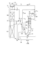
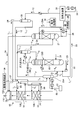
- FIG. 1 is a schematic diagram of a CO 2 recovery apparatus according to the first embodiment.
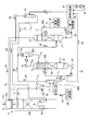
- FIG. 2 is an enlarged view of a component including the absorption tower and the concentration unit in FIG.
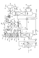
- FIG. 3 is a schematic diagram of a CO 2 recovery apparatus according to the second embodiment.
- FIG. 4 is an enlarged view of a component including the absorption tower and the concentration unit in FIG.
- FIG. 5 is a schematic diagram of another CO 2 recovery apparatus according to the second embodiment.
- FIG. 6 is a schematic diagram of a CO 2 recovery device according to the third embodiment.
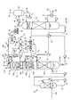
- FIG. 7 is an enlarged view of a component including the absorption tower and the concentration unit in FIG.
- FIG. 8 is a schematic diagram of a CO 2 recovery apparatus according to the fourth embodiment.
- FIG. 1 is a schematic diagram of a CO 2 recovery apparatus according to the first embodiment.
- FIG. 2 is an enlarged view of a component including the absorption tower and the concentration unit in FIG.
- FIG. 3 is a schematic diagram of a CO 2
- FIG. 9 is an enlarged view of a component including the absorption tower and the concentration unit in FIG.
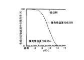
- FIG. 10 is a relationship diagram between pH and the residual ratio of each component in the extracted liquid.
- FIG. 11 is a graph showing the relationship between pH and the recovery rate of each volatile basic component in the acid treatment solution.
- FIG. 1 is a schematic diagram of a CO 2 recovery apparatus according to the first embodiment.
- CO 2 recovery apparatus 10A according to the present embodiment, CO 2 containing exhaust gas 11A and the CO 2 absorbing liquid containing CO 2 with (lean solution 12B) and contacting the removing CO 2 CO and 2 absorber (hereinafter referred to as "absorption column") 13, an absorbing solution regeneration tower 14 for reproducing CO 2 absorbent having absorbed CO 2 (the rich solution 12A), said absorbent regenerator (hereinafter referred to as "regeneration tower” ) 14 lean solution 12B which CO 2 has been removed by a CO 2 reused in the CO 2 absorber 13, the CO 2 absorption tower 13, CO in the CO 2 absorbing liquid 12 (lean solution 12B) 2 CO 2 absorber 13A that absorbs CO 2 in the contained exhaust gas 11A, and an CO 2 removal exhaust gas 11B that is provided on the upper side (gas flow downstream) side of the
- the CO 2 -containing exhaust gas 11 ⁇ / b > A is in counterflow contact with the CO 2 absorption liquid 12 based on, for example, an alkanolamine in a CO 2 absorption section 13 ⁇ / b > A provided on the lower side of the CO 2 absorption tower 13.
- CO 2 in the CO 2 containing exhaust gas 11A is absorbed by the CO 2 absorbing liquid 12 by a chemical reaction (R-NH 2 + H 2 O + CO 2 ⁇ R-NH 3 HCO 3).
- the CO 2 flue gas 11B after CO 2 removal rises to the water washing section 13B side via the chimney tray 16, and gas-liquid contact with washing water 20 supplied from the top side of the washing unit 13B, CO 2 removal
- the CO 2 absorbent 12 accompanying the exhaust gas 11B is recovered. Thereafter, the CO 2 absorbent-removed exhaust gas 11C from which the CO 2 absorbent 12 has been removed is discharged from the top 13C of the CO 2 absorber 13 to the outside.
- Reference numeral 73 denotes a mist eliminator that captures mist in the gas.
- the rich solution 12 ⁇ / b > A that has absorbed CO 2 is pressurized by a rich solvent pump 51 interposed in the rich solution supply pipe 50, and the lean solution 12 ⁇ / b> B regenerated in the absorbent regenerator 14 in the rich / lean solution heat exchanger 52. And is supplied to the top side of the absorption liquid regeneration tower 14.
- the rich solution 12A released from the top side of the regeneration tower 14 into the tower releases most of the CO 2 by heating with water vapor from the bottom of the tower.
- the CO 2 absorbent 12 that has released part or most of the CO 2 in the regeneration tower 14 is referred to as a “semi-lean solution”.
- the semi-lean solution (not shown) flows down to the bottom of the regeneration tower 14, it becomes a lean solution 12B from which almost all of the CO 2 has been removed.
- the lean solution 12B is heated by saturated steam 62 in the regeneration heater 61 interposed in the circulation line L 20.
- the saturated steam 62 after heating becomes steam condensed water 63.
- the regenerated CO 2 absorbent (lean solution 12B) is sent to the CO 2 absorption tower 13 side by the lean solution pump 54 via the lean solution supply pipe 53, and is circulated and used as the CO 2 absorbent 12. Therefore, the CO 2 absorbing liquid 12 forms a closed path for circulating a CO 2 absorption tower 13 and the absorption solution regenerator 14 is reused in the CO 2 absorbing section 13A of the CO 2 absorber 13. Note that the CO 2 absorbent 12 is supplied from a replenishment line (not shown) as needed, and the CO 2 absorbent is regenerated by a reclaimer (not shown) as needed.
- the CO 2 -containing exhaust gas 11A supplied to the CO 2 absorption tower 13 is cooled by the cooling water 71 in the cooling tower 70 provided on the upstream side thereof, and then introduced into the CO 2 absorption tower 13. Incidentally, it is fed to the top 13C side of the washing unit 13B as wash water 20 of the CO 2 absorber 13 also CO 2 absorbing solution portion of the cooling water 71, the cleaning of CO 2 absorbing liquid 12 accompanying the CO 2 flue gas 11B It may be used for Reference numeral 72 denotes a circulation pump, 75 denotes a cooler, and 74 denotes a circulation line.
- the CO 2 absorbing liquid 12 to be circulated utilizing the CO 2 absorption tower 13 and the absorption solution regenerator 14 is in the washing unit 13B, and the CO 2 flue gas 11B which CO 2 has been removed, the washing water 20 Are counter-flow contacted, and the CO 2 absorbing liquid 12 entrained in the CO 2 removal exhaust gas 11B is absorbed and removed by the washing water 20 to prevent the absorption to the outside of the absorption tower 13.
- a concentrating unit 22 is provided so that the CO 2 absorbent 12 is concentrated.
- FIG. 2 is an enlarged view of a component including the absorption tower 13 and the concentration unit 22 in FIG.
- the concentration unit 22 includes a first gas-liquid separation unit 22A and a concentration tower 22B.
- a part of the washing water 20 containing the CO 2 absorbent 12 is drawn out from the circulation line L 1 that circulates the washing water 20 as the drawing liquid 21 through the drawing line L 2. It introduces into the liquid separation part 22A.
- the extracted liquid 21 is diffused to separate the gas body and the liquid, and the gas component 24 is separated from the extracted liquid 21.
- the gas component 24 is, for example, ammonia gas having high volatility such as ammonia contained in the CO 2 absorbent 12 and is supplied to the gas introduction line L 4 via the supply line L 4F .
- the extracted liquid 21 from which the gas component 24 has been separated by the first gas-liquid separation unit 22A is joined to the concentrated liquid circulation line L 6 of the concentrated tower 22B via the supply line L 5 .
- the air 31 is blown into the concentrating tower 22B from the bottom side, and the gas component 24 remaining in the circulating extract 21 is further extracted.
- the extracted liquid 21 merged with the concentrated liquid 23 flows into the tower from the top, and the concentrated liquid 23 that has flowed in, for example, the surface of the packed material such as the packed section 60 on the bottom side.
- the highly volatile gas component 24 comes into contact with the air 31 introduced from the bottom side and diffuses into the air.
- the dissipated gas component 24 via the gas introduction line L 4 is introduced into the downstream (top portion) side of the washing unit 13B, with CO 2 absorbing liquid 12 CO 2 absorbing solution removed exhaust 11C which is removed , And is discharged to the outside from the top of the CO 2 absorber 13.
- the supply line L 4A from which the gas component 24 is led out from the top of the concentrating tower 22B is provided with a separation drum 22C. Preventing the escape of moisture outside the system.
- the gas component 24 separated by the separation drum 22C is led to the gas introduction line L 4 via the supply line L 4B .
- the liquid separated by the separation drum 22C is returned to the concentration tower 22B through the supply line L 4C .
- the gas component 24 is introduced to the tower top side of the absorption tower 13, it is discharged to the outside as it is. Therefore, when the gas regulation is high, it is introduced to the downstream (tower top) side of the water washing part 13B. You may make it do.
- the concentrated solution 23 in which the CO 2 absorbing solution is concentrated by circulating through the concentrating tower 22B is supplied to the CO 2 absorbing unit 13A on the upstream side (tower bottom) side of the water washing unit 13B via the concentrated solution return line L 3. And reused as the CO 2 absorbent 12.
- the concentrated solution returning line L 3 for returning the concentrated solution 23 is connected to the lean solution pump of the lean solution supply pipe 53. is combined to the suction side 54, together with the lean solution 12B, is introduced into the CO 2 absorbing section 13A, it is reused as the CO 2 absorbing liquid 12.
- the return line L 3 to return the concentrate 23 may be separately introduced into the CO 2 absorbing section 13A.
- the concentration of the basic amine compounds in the absorption liquid remaining in the decarbonized exhaust gas and released to the outside can be further reduced, and the collected absorption liquid can be concentrated and reused. it can.
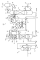
- FIG. 3 is a schematic diagram of a CO 2 recovery apparatus according to the second embodiment.
- FIG. 4 is an enlarged view of a component including the absorption tower and the concentration unit in FIG. CO 2 recovery apparatus 10A same configuration as that according to the first embodiment shown in FIG. 1, and redundant description are denoted by the same reference numerals will be omitted.
- an alkali for example, sodium hydroxide
- a supply unit 33 is provided, and the pH of the extracted liquid 21 is adjusted in the first gas-liquid separation unit 22A.
- sodium hydroxide can be used as the alkali 32 supplied here, but the present invention is not limited to this.
- the alkali 32 include sodium carbonate, potassium hydroxide, potassium carbonate, calcium hydroxide, calcium carbonate and the like in addition to sodium hydroxide.
- the volatile basic component contained in the gas component 24 is separated by adding the alkali 32 to the first gas-liquid separation unit 22A, the volatile basic component is recovered by acid treatment.
- An acid cleaning tower 27 as a volatile basic component recovery unit is provided to recover and remove volatile basic components in the gas component 24 separated from the first gas-liquid separation unit 22A and the concentration tower 22B. I am doing so.
- Acid washing tower 27 is added acid 29 in the supply line L 7 from the acid supply unit 28, is recovered by acid treatment liquid 29A in as the sulphate, treated with waste liquid treatment portion 30 through the supply line L 8 Yes.
- sulfuric acid can be used as the acid 29 to be added here, but the present invention is not limited to this.
- the acid 29 include hydrochloric acid, phosphoric acid, boric acid, carbonic acid, oxalic acid and the like in addition to sulfuric acid.
- FIG. 10 is a relationship diagram between pH and the residual ratio of each component in the extracted liquid.
- the extracted liquid 21 contains the CO 2 absorbent 12, the washing water 20, and a volatile basic component.
- volatile basic components (gas components) A having a low boiling point such as ammonia are mostly vaporized by the dissipating action of the first gas-liquid separator 22A.
- the behavior of the volatile basic component (gas component) B having a higher boiling point is different from that of the gas component A. That is, assuming that the predetermined pH corresponding to the type of the absorbing liquid is the “reference pH”, the gas component B changes from the liquid side to the gas side as the pH is raised from the reference pH to the +1 to +4 side.
- the first gas-liquid separation unit 22A of the concentration unit 22 when the pH is set to the reference value (0), only the volatile basic component (gas component) A is a gas component as shown in FIG. 24.
- the first gas-liquid separation unit 22A of the concentration unit 22 when the alkali 32 is added and the pH is raised to the +1 to +4 side from the reference value, as shown in FIG. Since not only the basic component (gas component) A but also the volatile basic component (gas component) B is included in the gas component 24, most of the volatile basic component (gas component) from the concentrate 23. ) A and B can be separated.
- the separated volatile basic component (gas component) B is contained in the gas component 24 as it is and is introduced to the absorption tower 13 side by the gas introduction line L 4. Therefore, in this embodiment, the acid washing tower is used. 27 is provided and is recovered as a sulfate by an acid treatment in which an acid 29 is added to prevent entrainment on the gas component 24 side.
- FIG. 11 is a graph showing the relationship between pH and the recovery rate of each volatile basic component in the acid treatment solution.
- FIG. 11 when a predetermined acid is added and the pH is set to the reference value (0), most of the volatile basic components (gas components) A and B are acid as shown in FIG. Present in the processing solution.
- the addition amount of the acid 29 in the acid washing tower 27 is reduced and the pH is raised to the +1 to 3 side (alkaline side) from the reference value, as shown in FIG.
- the component (gas component) B remains in the acid treatment liquid, and the volatile basic component (gas component) A is separated as a gas. Since this volatile basic component (gas component) A is ammonia or the like, when there is no ammonia regulation, it is introduced to the absorption tower 13 side by the gas introduction line L 4 and discharged to the outside.
- the volatile basic component can be separated and recovered by adjusting the pH during the acid treatment.
- the concentrated solution 23 cannot be returned to the CO 2 absorbent 12 side as it is in the first embodiment. This is because the pH increases due to the addition of alkali and becomes the alkali side, so when returning to the absorption tower 13 side as it is, the added alkali accumulates in the absorption liquid 12 and causes a change in pH balance. is there.
- the auxiliary regeneration device 38 is provided, and the alkali 32 is further added to the concentrated solution 23 to make it a strong alkali side, and regeneration is performed by indirectly exchanging heat using saturated steam (not shown) under this strong alkali condition.
- the CO 2 absorbent 12 is vaporized.
- the vaporized CO 2 absorption liquid is gas-liquid separated from the gas component 24 containing water vapor and the CO 2 absorption liquid 12 by the second gas-liquid separation unit 39.
- the separated CO 2 absorbing liquid 12 was via a supply line L 10, and then returned to the upstream (CO 2 absorbing section 13A) side of the washing unit 13B.
- the gas components 24 such as steam through a supply line L 11, and then returned to the top of 13C.
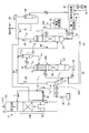
- FIG. 5 is a schematic diagram of another CO 2 recovery apparatus according to the second embodiment.
- the water washing section 13B of the absorption tower 13 is a single stage, but in the CO 2 recovery apparatus 10C shown in FIG. 5, a two-stage water washing section (lower stage) 13B 1 , a water washing section It is the (upper) 13B 2.
- the number of stages is not limited to two and may be three or more.
- CO 2 absorbing liquid 12 in the case of the present embodiment is then returned to the water washing section 13B 1 side of the lower stage side via the supply line L 10.
- FIG. 6 is a schematic diagram of a CO 2 recovery device according to the third embodiment.
- the same components as those of the CO 2 recovery apparatuses 10A, 10B, and 10C according to the first embodiment illustrated in FIGS. 1, 3, and 5 are denoted by the same reference numerals, and redundant description is omitted.
- the acidic liquid 37 is supplied from the acidic liquid supply unit 36 to the circulation line L 1 of the water washing unit (upper stage) 13B 2 to make the cleaning water 20 acidic. Since the acidic cleaning water 20 is used, the degree of absorption of the CO 2 absorbing liquid in the water cleaning section is improved.
- the extraction liquid 21 is also acidic, the alkali 32 is supplied to the extraction liquid 21 to release it from ions to a free state, thereby facilitating vaporization of basic volatile components.
- the absorption liquid (gas state) is separated, the accompanying gas component 24 is separated by the second gas-liquid separation device 39, and returned to the absorption tower 13 side as a regenerated absorption liquid.
- gas Ingredient 24 is fed to the acid wash line.
- the vaporized gas of the CO 2 absorbent 12 from the sub-regenerator 38 is sent to the gas / liquid separator 39 via the supply line L 9 .
- the gas component 24 is returned to the tower top side of the water washing section 13B 2 via the supply line L 4 , and the regenerated CO 2 absorbent 12 is supplied to the first water washing section (lower stage) 13B 1 via the supply line L 10. Back to the side.
- FIG. 8 is a schematic diagram of a CO 2 recovery apparatus according to the fourth embodiment.
- the same components as those of the CO 2 recovery apparatuses 10A, 10B, and 10C according to the first embodiment illustrated in FIGS. 1, 3, and 5 are denoted by the same reference numerals, and redundant description is omitted.
- the CO 2 recovery apparatus 10E according to the present embodiment in the concentrating tower 22B of the second embodiment, instead of supplying the air 31, the water vapor 35 is supplied and the gas component 24 is expelled by the water vapor 35.
- the return destination of the gas component 24 is not introduced to the absorption tower 13 side as in the second embodiment, but is introduced into the top 14A of the regeneration tower 14.
- the air 31 is mixed into the recovered CO 2 . Contamination of the air 31 as the recovered CO 2, becomes a contamination of impurities, the purity of the recovered CO 2 is reduced.
- the concentration of the basic amine compounds remaining in the decarbonation exhaust gas and released can be further reduced, and the concentrated absorbent can be effectively used again.
- CO 2 recovery device 11A CO 2 -containing exhaust gas 12 CO 2 absorbent 12A rich solution 12B lean solution 13 CO 2 absorption tower (absorption tower) 14 Absorption liquid regeneration tower (regeneration tower) 20 Washing Water 21 Extracted Liquid 22 Concentrating Section 22A First Gas-Liquid Separating Section 22B Concentrating Tower 23 Concentrated Liquid 24 Gas Components
Landscapes
- Chemical & Material Sciences (AREA)
- Chemical Kinetics & Catalysis (AREA)
- Engineering & Computer Science (AREA)
- Analytical Chemistry (AREA)
- General Chemical & Material Sciences (AREA)
- Oil, Petroleum & Natural Gas (AREA)
- Organic Chemistry (AREA)
- Inorganic Chemistry (AREA)
- Treating Waste Gases (AREA)
- Gas Separation By Absorption (AREA)
- Physical Water Treatments (AREA)
- Carbon And Carbon Compounds (AREA)
Priority Applications (4)
| Application Number | Priority Date | Filing Date | Title |
|---|---|---|---|
| AU2012254506A AU2012254506A1 (en) | 2011-05-12 | 2012-05-10 | CO2 recovery device, and CO2 recovery method |
| US14/005,970 US20140013945A1 (en) | 2011-05-12 | 2012-05-10 | Co2 recovery device and co2 recovery method |
| CA2834667A CA2834667A1 (en) | 2011-05-12 | 2012-05-10 | Co2 recovery device and co2 recovery method |
| EP12782974.5A EP2719441A1 (en) | 2011-05-12 | 2012-05-10 | Co2 recovery device, and co2 recovery method. |
Applications Claiming Priority (2)
| Application Number | Priority Date | Filing Date | Title |
|---|---|---|---|
| JP2011-107695 | 2011-05-12 | ||
| JP2011107695A JP2012236166A (ja) | 2011-05-12 | 2011-05-12 | Co2回収装置およびco2回収方法 |
Publications (1)
| Publication Number | Publication Date |
|---|---|
| WO2012153812A1 true WO2012153812A1 (ja) | 2012-11-15 |
Family
ID=47139287
Family Applications (1)
| Application Number | Title | Priority Date | Filing Date |
|---|---|---|---|
| PCT/JP2012/062035 WO2012153812A1 (ja) | 2011-05-12 | 2012-05-10 | Co2回収装置およびco2回収方法 |
Country Status (6)
Cited By (3)
| Publication number | Priority date | Publication date | Assignee | Title |
|---|---|---|---|---|
| WO2013039040A1 (ja) * | 2011-09-13 | 2013-03-21 | 三菱重工業株式会社 | Co2回収装置およびco2回収方法 |
| WO2013039041A1 (ja) * | 2011-09-13 | 2013-03-21 | 三菱重工業株式会社 | Co2回収装置およびco2回収方法 |
| JP2019178056A (ja) * | 2018-03-30 | 2019-10-17 | 三菱マテリアル株式会社 | 二酸化炭素製造装置、二酸化炭素製造方法、二酸化炭素製造装置の設計方法 |
Families Citing this family (29)
| Publication number | Priority date | Publication date | Assignee | Title |
|---|---|---|---|---|
| WO2013169853A1 (en) * | 2012-05-09 | 2013-11-14 | Industries Llc Yknots | Device, method, and graphical user interface for providing tactile feedback for operations performed in a user interface |
| JP6004821B2 (ja) | 2012-08-08 | 2016-10-12 | 三菱重工業株式会社 | Co2回収装置およびco2回収方法 |
| JP6016513B2 (ja) * | 2012-08-09 | 2016-10-26 | 三菱重工業株式会社 | Co2回収装置およびco2回収方法 |
| US9623366B2 (en) | 2013-03-04 | 2017-04-18 | Mitsubishi Heavy Industries, Ltd. | CO2 recovery system and CO2 recovery method |
| CN103521053B (zh) * | 2013-09-27 | 2015-07-29 | 华中农业大学 | 基于吸收剂浓度变换的气体中co2化学吸收系统与方法 |
| CN103638775A (zh) * | 2013-12-09 | 2014-03-19 | 深圳市芭田生态工程股份有限公司 | 一种含氟氨水蒸汽处理方法 |
| CN104941419A (zh) * | 2014-03-31 | 2015-09-30 | 英尼奥斯欧洲股份公司 | 反应器流出物的改进的氨移除 |
| AU2015298710B2 (en) | 2014-08-02 | 2019-10-17 | Apple Inc. | Context-specific user interfaces |
| US10452253B2 (en) | 2014-08-15 | 2019-10-22 | Apple Inc. | Weather user interface |
| WO2016068698A1 (en) | 2014-10-27 | 2016-05-06 | Carbonoro B.V. | Process and apparatus for separating entrained amines from a gas stream |
| WO2016068699A1 (en) | 2014-10-27 | 2016-05-06 | Carbonoro B.V. | Process and apparatus for separating entrained amines from a gas stream |
| WO2016144385A1 (en) | 2015-03-08 | 2016-09-15 | Apple Inc. | Sharing user-configurable graphical constructs |
| US10304347B2 (en) | 2015-08-20 | 2019-05-28 | Apple Inc. | Exercised-based watch face and complications |
| EP3181540B1 (de) * | 2015-12-18 | 2019-07-24 | L'Air Liquide Société Anonyme pour l'Etude et l'Exploitation des Procédés Georges Claude | Verfahren zur trennung von methanol aus gasgemischen |
| US12175065B2 (en) | 2016-06-10 | 2024-12-24 | Apple Inc. | Context-specific user interfaces for relocating one or more complications in a watch or clock interface |
| US10467912B2 (en) * | 2017-03-14 | 2019-11-05 | Honeywell International Inc. | System and method to revise vertical profile of a flight plan |
| DK179412B1 (en) | 2017-05-12 | 2018-06-06 | Apple Inc | Context-Specific User Interfaces |
| US11819777B2 (en) | 2017-08-22 | 2023-11-21 | Saudi Arabian Oil Company | Systems and methods for enhancing amine agent recovery with a reclaimer |
| US11327650B2 (en) | 2018-05-07 | 2022-05-10 | Apple Inc. | User interfaces having a collection of complications |
| US11260336B2 (en) * | 2018-12-20 | 2022-03-01 | Entegris, Inc. | Active wet scrubbing filtration system |
| AU2020239670B2 (en) | 2019-05-06 | 2021-07-15 | Apple Inc. | Restricted operation of an electronic device |
| US10878782B1 (en) | 2019-09-09 | 2020-12-29 | Apple Inc. | Techniques for managing display usage |
| DK202070624A1 (en) | 2020-05-11 | 2022-01-04 | Apple Inc | User interfaces related to time |
| WO2021231345A1 (en) | 2020-05-11 | 2021-11-18 | Apple Inc. | User interfaces for managing user interface sharing |
| US11694590B2 (en) | 2020-12-21 | 2023-07-04 | Apple Inc. | Dynamic user interface with time indicator |
| US11720239B2 (en) | 2021-01-07 | 2023-08-08 | Apple Inc. | Techniques for user interfaces related to an event |
| US12182373B2 (en) | 2021-04-27 | 2024-12-31 | Apple Inc. | Techniques for managing display usage |
| US11921992B2 (en) | 2021-05-14 | 2024-03-05 | Apple Inc. | User interfaces related to time |
| US20230236547A1 (en) | 2022-01-24 | 2023-07-27 | Apple Inc. | User interfaces for indicating time |
Citations (6)
| Publication number | Priority date | Publication date | Assignee | Title |
|---|---|---|---|---|
| JPH05245340A (ja) * | 1992-03-03 | 1993-09-24 | Kansai Electric Power Co Inc:The | 燃焼排ガスの処理方法 |
| JPH0880421A (ja) | 1991-03-07 | 1996-03-26 | Mitsubishi Heavy Ind Ltd | 燃焼排ガスの脱炭酸ガス装置及び方法 |
| JP2002126439A (ja) | 2000-10-25 | 2002-05-08 | Kansai Electric Power Co Inc:The | アミン回収方法及び装置並びにこれを備えた脱炭酸ガス装置 |
| JP2008296216A (ja) * | 2007-06-04 | 2008-12-11 | Posco | アンモニア水を利用する二酸化炭素回収装置及びその方法 |
| WO2010102877A1 (en) * | 2009-03-13 | 2010-09-16 | Aker Clean Carbon As | Method and plant for amine emission control |
| JP2010253370A (ja) * | 2009-04-23 | 2010-11-11 | Mitsubishi Heavy Ind Ltd | Co2回収装置及びco2回収方法 |
-
2011
- 2011-05-12 JP JP2011107695A patent/JP2012236166A/ja not_active Ceased
-
2012
- 2012-05-10 WO PCT/JP2012/062035 patent/WO2012153812A1/ja active Application Filing
- 2012-05-10 EP EP12782974.5A patent/EP2719441A1/en not_active Withdrawn
- 2012-05-10 AU AU2012254506A patent/AU2012254506A1/en not_active Abandoned
- 2012-05-10 CA CA2834667A patent/CA2834667A1/en not_active Abandoned
- 2012-05-10 US US14/005,970 patent/US20140013945A1/en not_active Abandoned
Patent Citations (6)
| Publication number | Priority date | Publication date | Assignee | Title |
|---|---|---|---|---|
| JPH0880421A (ja) | 1991-03-07 | 1996-03-26 | Mitsubishi Heavy Ind Ltd | 燃焼排ガスの脱炭酸ガス装置及び方法 |
| JPH05245340A (ja) * | 1992-03-03 | 1993-09-24 | Kansai Electric Power Co Inc:The | 燃焼排ガスの処理方法 |
| JP2002126439A (ja) | 2000-10-25 | 2002-05-08 | Kansai Electric Power Co Inc:The | アミン回収方法及び装置並びにこれを備えた脱炭酸ガス装置 |
| JP2008296216A (ja) * | 2007-06-04 | 2008-12-11 | Posco | アンモニア水を利用する二酸化炭素回収装置及びその方法 |
| WO2010102877A1 (en) * | 2009-03-13 | 2010-09-16 | Aker Clean Carbon As | Method and plant for amine emission control |
| JP2010253370A (ja) * | 2009-04-23 | 2010-11-11 | Mitsubishi Heavy Ind Ltd | Co2回収装置及びco2回収方法 |
Cited By (6)
| Publication number | Priority date | Publication date | Assignee | Title |
|---|---|---|---|---|
| WO2013039040A1 (ja) * | 2011-09-13 | 2013-03-21 | 三菱重工業株式会社 | Co2回収装置およびco2回収方法 |
| WO2013039041A1 (ja) * | 2011-09-13 | 2013-03-21 | 三菱重工業株式会社 | Co2回収装置およびco2回収方法 |
| JP2013059726A (ja) * | 2011-09-13 | 2013-04-04 | Mitsubishi Heavy Ind Ltd | Co2回収装置およびco2回収方法 |
| US9421491B2 (en) | 2011-09-13 | 2016-08-23 | Mitsubishi Heavy Industries, Ltd. | CO2 recovery apparatus and CO2 recovery method |
| JP2019178056A (ja) * | 2018-03-30 | 2019-10-17 | 三菱マテリアル株式会社 | 二酸化炭素製造装置、二酸化炭素製造方法、二酸化炭素製造装置の設計方法 |
| JP7136577B2 (ja) | 2018-03-30 | 2022-09-13 | Ube三菱セメント株式会社 | 二酸化炭素製造装置、二酸化炭素製造方法、二酸化炭素製造装置の設計方法 |
Also Published As
| Publication number | Publication date |
|---|---|
| JP2012236166A (ja) | 2012-12-06 |
| AU2012254506A1 (en) | 2013-10-17 |
| EP2719441A1 (en) | 2014-04-16 |
| US20140013945A1 (en) | 2014-01-16 |
| CA2834667A1 (en) | 2012-11-15 |
Similar Documents
| Publication | Publication Date | Title |
|---|---|---|
| WO2012153812A1 (ja) | Co2回収装置およびco2回収方法 | |
| WO2013039041A1 (ja) | Co2回収装置およびco2回収方法 | |
| JP5738137B2 (ja) | Co2回収装置およびco2回収方法 | |
| JP5703106B2 (ja) | アミン回収システム及び二酸化炭素回収システム | |
| US8974582B2 (en) | CO2 recovery system and CO2 recovery method | |
| JP5875245B2 (ja) | Co2回収システム及びco2ガス含有水分の回収方法 | |
| JP6239519B2 (ja) | 脱硫装置およびそこで発生した凝縮水の使用方法 | |
| JP5968159B2 (ja) | Co2回収装置およびco2回収方法 | |
| US9138677B2 (en) | Ammonia stripper for a carbon capture system for reduction of energy consumption | |
| JP2011240321A (ja) | 二酸化炭素除去装置を有する排ガス処理システム | |
| JP6004821B2 (ja) | Co2回収装置およびco2回収方法 | |
| US9399189B2 (en) | CO2 recovery device | |
| JP6581768B2 (ja) | Co2回収装置およびco2回収方法 | |
| JP6811759B2 (ja) | Co2回収装置およびco2回収方法 | |
| JP2015020079A (ja) | 被処理ガス中の二酸化炭素を回収する方法およびそのための装置 |
Legal Events
| Date | Code | Title | Description |
|---|---|---|---|
| 121 | Ep: the epo has been informed by wipo that ep was designated in this application |
Ref document number: 12782974 Country of ref document: EP Kind code of ref document: A1 |
|
| WWE | Wipo information: entry into national phase |
Ref document number: 14005970 Country of ref document: US |
|
| ENP | Entry into the national phase |
Ref document number: 2012254506 Country of ref document: AU Date of ref document: 20120510 Kind code of ref document: A |
|
| WWE | Wipo information: entry into national phase |
Ref document number: 2012782974 Country of ref document: EP |
|
| ENP | Entry into the national phase |
Ref document number: 2834667 Country of ref document: CA |
|
| NENP | Non-entry into the national phase |
Ref country code: DE |