EP2719441A1 - Co2 recovery device, and co2 recovery method. - Google Patents
Co2 recovery device, and co2 recovery method. Download PDFInfo
- Publication number
- EP2719441A1 EP2719441A1 EP12782974.5A EP12782974A EP2719441A1 EP 2719441 A1 EP2719441 A1 EP 2719441A1 EP 12782974 A EP12782974 A EP 12782974A EP 2719441 A1 EP2719441 A1 EP 2719441A1
- Authority
- EP
- European Patent Office
- Prior art keywords
- absorbent
- gas
- unit
- absorber
- wash water
- Prior art date
- Legal status (The legal status is an assumption and is not a legal conclusion. Google has not performed a legal analysis and makes no representation as to the accuracy of the status listed.)
- Withdrawn
Links
Images


Classifications
-
- C—CHEMISTRY; METALLURGY
- C01—INORGANIC CHEMISTRY
- C01B—NON-METALLIC ELEMENTS; COMPOUNDS THEREOF; METALLOIDS OR COMPOUNDS THEREOF NOT COVERED BY SUBCLASS C01C
- C01B32/00—Carbon; Compounds thereof
- C01B32/50—Carbon dioxide
-
- B—PERFORMING OPERATIONS; TRANSPORTING
- B01—PHYSICAL OR CHEMICAL PROCESSES OR APPARATUS IN GENERAL
- B01D—SEPARATION
- B01D53/00—Separation of gases or vapours; Recovering vapours of volatile solvents from gases; Chemical or biological purification of waste gases, e.g. engine exhaust gases, smoke, fumes, flue gases, aerosols
- B01D53/14—Separation of gases or vapours; Recovering vapours of volatile solvents from gases; Chemical or biological purification of waste gases, e.g. engine exhaust gases, smoke, fumes, flue gases, aerosols by absorption
- B01D53/1418—Recovery of products
-
- B—PERFORMING OPERATIONS; TRANSPORTING
- B01—PHYSICAL OR CHEMICAL PROCESSES OR APPARATUS IN GENERAL
- B01D—SEPARATION
- B01D53/00—Separation of gases or vapours; Recovering vapours of volatile solvents from gases; Chemical or biological purification of waste gases, e.g. engine exhaust gases, smoke, fumes, flue gases, aerosols
- B01D53/14—Separation of gases or vapours; Recovering vapours of volatile solvents from gases; Chemical or biological purification of waste gases, e.g. engine exhaust gases, smoke, fumes, flue gases, aerosols by absorption
- B01D53/1456—Removing acid components
- B01D53/1475—Removing carbon dioxide
-
- B—PERFORMING OPERATIONS; TRANSPORTING
- B01—PHYSICAL OR CHEMICAL PROCESSES OR APPARATUS IN GENERAL
- B01D—SEPARATION
- B01D2258/00—Sources of waste gases
- B01D2258/02—Other waste gases
- B01D2258/0283—Flue gases
-
- Y—GENERAL TAGGING OF NEW TECHNOLOGICAL DEVELOPMENTS; GENERAL TAGGING OF CROSS-SECTIONAL TECHNOLOGIES SPANNING OVER SEVERAL SECTIONS OF THE IPC; TECHNICAL SUBJECTS COVERED BY FORMER USPC CROSS-REFERENCE ART COLLECTIONS [XRACs] AND DIGESTS
- Y02—TECHNOLOGIES OR APPLICATIONS FOR MITIGATION OR ADAPTATION AGAINST CLIMATE CHANGE
- Y02C—CAPTURE, STORAGE, SEQUESTRATION OR DISPOSAL OF GREENHOUSE GASES [GHG]
- Y02C20/00—Capture or disposal of greenhouse gases
- Y02C20/40—Capture or disposal of greenhouse gases of CO2
-
- Y—GENERAL TAGGING OF NEW TECHNOLOGICAL DEVELOPMENTS; GENERAL TAGGING OF CROSS-SECTIONAL TECHNOLOGIES SPANNING OVER SEVERAL SECTIONS OF THE IPC; TECHNICAL SUBJECTS COVERED BY FORMER USPC CROSS-REFERENCE ART COLLECTIONS [XRACs] AND DIGESTS
- Y02—TECHNOLOGIES OR APPLICATIONS FOR MITIGATION OR ADAPTATION AGAINST CLIMATE CHANGE
- Y02P—CLIMATE CHANGE MITIGATION TECHNOLOGIES IN THE PRODUCTION OR PROCESSING OF GOODS
- Y02P20/00—Technologies relating to chemical industry
- Y02P20/151—Reduction of greenhouse gas [GHG] emissions, e.g. CO2
Definitions
- the present invention relates to a CO 2 recovery device and a CO 2 recovery method reducing the concentrations of basic amine compounds that remain in a decarbonated flue gas from which CO 2 has been removed by the contact between an absorbent and the gas and are to be released.
- a greenhouse effect caused by CO 2 is pointed out as one of causes of a global warming phenomenon. Accordingly, measures to protect the environment of the earth have been urgently and internationally needed. Since a source of CO 2 corresponds to the whole field of human activity using the combustion of fossil fuel, a demand for the suppression of CO 2 emission tends to become stronger. Accordingly, a method of removing and recovering CO 2 , which is contained in a flue gas, by bringing a flue gas of a boiler into contact with an amine-based absorbent such as the aqueous solution of an amine compound has been energetically studied for power generation facilities such as thermoelectric power plants using a large amount of fossil fuel.
- Patent Literature 1 has disclosed a device provided with a washing unit that includes a plurality of stages and recovers an amine compound, which is accompanied by a decarbonated flue gas, by bringing wash water into gas-liquid contact with the decarbonated flue gas from which CO 2 has been absorbed and removed by the gas-liquid contact with an absorbent.
- the device sequentially recovers amine, which is accompanied by the decarbonated flue gas, by the plurality of stages of the washing unit.
- Condensed water, from which moisture contained in CO 2 has been condensed and separated in a process for regenerating an amine-based absorbent by removing CO 2 from the amine-based absorbent that has absorbed CO 2 is used as the wash water of Patent Literature 1.
- Patent Literature 2 has disclosed a device that includes a cooling unit that cools a decarbonated flue gas from which CO 2 has been absorbed and removed by the gas-liquid contact with an absorbent, and a contact unit that brings condensed water, which has been condensed by the cooling unit, into countercurrent contact with the decarbonated flue gas. Furthermore, Patent Literature 2 has disclosed a device includes a washing unit that recovers an amine compound, which is accompanied by a decarbonated flue gas, by bringing wash water into gas-liquid contact with the decarbonated flue gas from which CO 2 has been absorbed and removed by the gas-liquid contact with an absorbent. Condensed water, which is condensed by a cooler that cools a flue gas from which CO 2 is not yet recovered, is used as the wash water.
- the invention has been made to solve the above-mentioned problem, and an object of the invention is to provide a CO 2 recovery device and a CO 2 recovery method capable of further reducing the concentrations of basic amine compounds that remain in a decarbonated flue gas and are to be released.
- a CO 2 recovery device including: a CO 2 absorber for bringing a CO 2 -containing flue gas, which contains CO 2 , into contact with a CO 2 absorbent, so as to remove CO 2 and an absorbent regenerator for separating CO 2 from the CO 2 absorbent having absorbed CO 2 , so as to regenerate the CO 2 absorbent, the CO 2 recovery device reusing a lean solution, from which CO 2 has been removed in the absorbent regenerator, in the CO 2 absorber, wherein the CO 2 absorber includes: a CO 2 absorption unit for absorbing CO 2 , which is contained in the CO 2 -containing flue gas, by the CO 2 absorbent; a washing unit provided downstream of the CO 2 absorption unit on a gas flow, for cooling a CO 2 -removed flue gas by wash water and recovering the accompanying CO 2 absorbent; a circulation line for supplying the wash water containing the CO 2 absorbent, which is recovered by the washing
- the CO 2 recovery device further including: an alkali supply unit that adjusts a pH of the extracted fluid by adding an alkali to the first gas-liquid separation unit; an acid washer for recovering a volatile basic component from the gas component, which is separated by the concentration unit, by an acid; and a sub-regeneration unit for regenerating the CO 2 absorbent from the concentrated fluid concentrated by the concentration unit.
- the CO 2 recovery device according to the first or second aspect, wherein the washing unit includes a plurality of stages.
- the CO 2 recovery device according to the first or second aspect, wherein the washing unit includes a plurality of stages, the wash water is circulated in each stage, and an acid is added to the wash water circulated in the uppermost stage of the washing unit.
- the CO 2 recovery device according to any one of the first to fourth aspects, wherein the concentration of the concentration unit is performed by air or steam.
- CO 2 recovery method by using a CO 2 absorber for bringing a CO 2 -containing flue gas, which contains CO 2 , into contact with a CO 2 absorbent so as to remove CO 2 and an absorbent regenerator for separating CO 2 from the CO 2 absorbent having absorbed CO 2 so as to regenerate the CO 2 absorbent, CO 2 of the lean solution having been removed in an absorbent regenerator, in a CO 2 absorber and by resusing a lean solution in a CO 2 absorber, CO2 of the lean solution having being removed in the absorbent regenerator, the CO 2 recovery method including: cooling a CO 2 -removed flue gas by wash water downstream the CO 2 absorber and extracting a part of a washing unit, which recovers the accompanying CO 2 absorbent, as an extracted fluid; and separating a gas component by separating the gas component from the extracted fluid and then concentrating the CO 2 absorbent contained in the extracted fluid.
- the CO 2 recovery method wherein an alkali is added to adjust a pH of the extracted fluid when the gas component is separated from the extracted fluid, and a volatile basic component contained in the gas component is recovered by an acid, and the CO 2 absorbent is regenerated from the concentrated fluid.
- the CO 2 recovery method according to the sixth or seventh aspect wherein concentration is performed by air or steam.
- the invention will be described in detail below with reference to the drawings. Meanwhile, the invention is not limited by this embodiment. Further, when the invention includes a plurality of embodiments, the invention also includes the combination of the respective embodiments. Further, elements of the following embodiments include elements that can be easily supposed by those skilled in the art, or substantially the same elements as the elements.
- FIG. 1 is a schematic diagram of a CO 2 recovery device according to a first embodiment.
- a CO 2 recovery device 10A includes: a CO 2 absorber (hereinafter, referred to as an "absorber”) 13 that removes CO 2 by bringing a CO 2 -containing flue gas 11A, which contains CO 2 , into contact with a CO 2 absorbent (lean solution 12B); and an absorbent regenerator 14 that regenerates a CO 2 absorbent having absorbed CO 2 (rich solution 12A).
- the CO 2 recovery device reuses the lean solution 12B, from which CO 2 has been removed in the absorbent regenerator (hereinafter, referred to as a "regenerator") 14, in the CO 2 absorber 13.
- the CO 2 absorber 13 includes: a CO 2 absorption unit 13A that absorbs CO 2 , which is contained in the CO 2 -containing flue gas 11A, by a CO 2 absorbent 12 (lean solution 12B); a washing unit 13B that is provided above the CO 2 absorption unit 13A (on the downstream side of gas flow), cools a CO 2 -removed flue gas 11B, and recovers the accompanying CO 2 absorbent 12; a circulation line L 1 that directly circulates wash water 20 containing the CO 2 absorbent 12, which is recovered by the washing unit 13B, from the top portion of the washing unit 13B; an extraction line L 2 that extracts a part of the wash water 20, which contains the CO 2 absorbent 12, as an extracted fluid 21 from the circulation line L 1 ; a first gas-liquid separation unit 22A that separates a gas component 24 from the extracted fluid 21; a concentrator 22B that concentrates the CO 2 absorbent 12 contained in the extracted fluid 21 and separates the gas component 24; a concentrated fluid return line L 3 through which
- the CO 2 -containing flue gas 11A comes into countercurrent contact with the CO 2 absorbent 12, which uses, for example, alkanolamine as a base, in the CO 2 absorption unit 13A provided at the lower portion of the CO 2 absorber 13, and CO 2 contained in the CO 2 -containing flue gas 11A is absorbed in the CO 2 absorbent 12 by a chemical reaction (R-NH 2 + H 2 O + CO 2 ⁇ R-NH 3 HCO 3 ).
- the CO 2 -removed flue gas 11B from which CO 2 has been removed rises toward the washing unit 13B through a chimney tray 16, comes into gas-liquid contact with the wash water 20 that is supplied from the top portion of the washing unit 13B, and recovers the CO 2 absorbent 12 accompanied by the CO 2 -removed flue gas 11B.
- a CO 2 absorbent-removed flue gas 11C from which the CO 2 absorbent 12 has been removed is discharged to the outside from a top portion 13C of the CO 2 absorber 13.
- reference numeral 73 denotes a mist eliminator that catches mist contained in a gas.
- the pressure of the rich solution 12A, which has absorbed CO 2 , is increased by a rich solvent pump 51 provided on a rich solution supply line 50, and the rich solution 12A is heated at a rich/lean solution heat exchanger 52 by the lean solution 12B, which is regenerated in the absorbent regenerator 14, and is supplied toward the top portion of the absorbent regenerator 14.
- the rich solution 12A which is released into the regenerator 14 from the top portion of the regenerator 14, releases most of CO 2 by being heated by steam that is supplied from the bottom portion of the regenerator 14.
- the CO 2 absorbent 12, which has released a part or most of CO 2 in the regenerator 14, is referred to as a "semi-lean solution".
- a semi-lean solution (not illustrated) becomes the lean solution 12B from which almost all CO 2 has been removed, by the time the semi-lean solution flows on the bottom portion of the regenerator 14.
- the lean solution 12B is heated at a regenerating heater 61, which is provided on a circulation line L 20 , by saturated steam 62.
- the saturated steam 62 which has been heated, becomes steam condensed water 63.
- the CO 2 gas 41 accompanying steam is led through a gas discharge line L 21 , the steam is condensed by a condenser 42 provided on the gas discharge line L 21 , condensed water 44 is separated in a separation drum 43, a CO 2 gas 45 is released to the outside of the system, and after treatment, such as separate compressing or recovering, is performed.
- the condensed water 44 which is separated in the separation drum 43, is supplied to the upper portion of the absorbent regenerator 14 by a condensed water circulating pump 46 that is provided on a condensed water line L 22 .
- a part of the condensed water 44 is supplied to the top portion 13C of the washing unit 13B as wash water 20 for the CO 2 absorbent and is used for the absorption of the CO 2 absorbent 12 accompanied by the CO 2 -removed flue gas 11B.
- the regenerated CO 2 absorbent (lean solution 12B) is sent to the CO 2 absorber 13 through a lean solution supply line 53 by a lean solution pump 54, and is circulated and used as the CO 2 absorbent 12.
- the CO 2 absorbent 12 forms a closed path through which the CO 2 absorbent 12 is circulated in the CO 2 absorber 13 and the absorbent regenerator 14, and is reused in the CO 2 absorption unit 13A of the CO 2 absorber 13. Meanwhile, the CO 2 absorbent 12 is supplied through a supply line (not illustrated) as necessary, and the CO 2 absorbent is regenerated by a reclaimer (not illustrated) as necessary.
- the CO 2 -containing flue gas 11A which is to be supplied to the CO 2 absorber 13, is cooled in a cooler 70, which is provided in the front stage of the CO 2 absorber 13, by cooling water 71. After that, the CO 2 -containing flue gas 11A is introduced into the CO 2 absorber 13. Meanwhile, there is a case in which a part of the cooling water 71 is also supplied to the top portion 13C of the washing unit 13B as the wash water 20 of the CO 2 absorber 13 for the CO 2 absorbent and is used for the washing of the CO 2 absorbent 12 accompanied by the CO 2 -removed flue gas 11B. Meanwhile, reference numeral 72 denotes a circulating pump, reference numeral 75 denotes a cooler, and reference numeral 74 denotes a circulation line.
- the CO 2 -removed flue gas 11B from which CO 2 has been removed comes into countercurrent contact with the wash water 20 in the washing unit 13B, so that the CO 2 absorbent 12 accompanied by the CO 2 -removed flue gas 11B is absorbed and removed by the wash water 20. Accordingly, the diffusion of the CO 2 absorbent 12, which is circulated and used in the CO 2 absorber 13 and the absorbent regenerator 14, to the outside of the absorber 13 is prevented.
- a concentration unit 22 is provided to reuse the CO 2 absorbent 12, which is absorbed and removed by the wash water 20, and concentrates and uses the CO 2 absorbent 12.
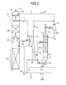
- FIG. 2 is an enlarged view of a component portion including the absorber 13 and the concentration unit 22 of FIG. 1 .
- the concentration unit 22 includes a first gas-liquid separation unit 22A and a concentrator 22B.
- the washing unit 13B extracts a part of the wash water 20, which contains CO 2 absorbent 12, as an extracted fluid 21 from the circulation line L 1 , which circulates wash water 20, through the extraction line L 2 and introduces the extracted fluid 21 into the first gas-liquid separation unit 22A.
- the first gas-liquid separation unit 22A separates a gas from liquid by diffusing the extracted fluid 21 and separates a gas component 24 from the extracted fluid 21.
- This gas component 24 is a highly volatile component such as ammonia contained in the CO 2 absorbent 12, for example, an ammonia gas, and is supplied to the gas inlet line L 4 through a supply line L 4F .
- the extracted fluid 21 from which the gas component 24 has been separated by the first gas-liquid separation unit 22A joins a concentrated fluid circulation line L 6 of the concentrator 22B through a supply line L 5 .
- Air 31 is blown into the concentrator 22B from the bottom side of the concentrator so that a gas component 24 remaining in the circulating extracted fluid 21 is further extracted.
- the extracted fluid 21 joining the concentrated fluid 23 flows into the concentrator 22B from the top portion of the concentrator 22B, and a highly volatile gas component 24 comes into contact with the air 31 introduced from the bottom side and is diffused to the air while the concentrated fluid 23 having flowed into the concentrator flows down to the bottom side along the surface of a filler of, for example, a filling unit 60 or the like.
- the diffused gas component 24 is introduced to the downstream side of the washing unit 13B (the top portion of the CO 2 absorber 13) through the gas inlet line L 4 , and is released to the outside from the top portion of the CO 2 absorber 13 together with the CO 2 absorbent-removed flue gas 11C from which the CO 2 absorbent 12 has been removed.
- a separation drum 22C is provided on a supply line L 4A through which the gas component 24 is led from the top portion of the concentrator 22B, and separates moisture from the gas component 24. Accordingly, the accompanying of moisture to the outside is prevented, so that the dispersion of moisture to the outside of the system is prevented.
- the gas component 24, which is separated by the separation drum 22C, is led to the gas inlet line L 4 through a supply line L 4B .
- liquid which is separated by the separation drum 22C, returns to the concentrator 22B through a supply line L 4c .
- the gas component 24 is released to the outside as it is. Accordingly, when gas regulations are strict, the gas component 24 may be introduced to the downstream side of the washing unit 13B (the top portion of the CO 2 absorber 13).
- the concentrated fluid return line L 3 through which the concentrated fluid 23 returns joins a portion of the lean solution supply line 53 corresponding to the suction side of the lean solution pump 54 and the concentrated fluid 23 is introduced into the CO 2 absorption unit 13A together with the lean solution 12B and is reused as the CO 2 absorbent 12.
- the return line L 3 through which the concentrated fluid 23 returns may be separately introduced into the CO 2 absorption unit 13A.
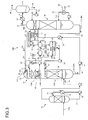
- FIG. 3 is a schematic diagram of a CO 2 recovery device according to a second embodiment.
- FIG. 4 is an enlarged view of a component portion including an absorber and a concentration unit of FIG. 3 .
- the same elements as the elements of the CO 2 recovery device 10A according to the first embodiment illustrated in FIG. 1 are denoted by the same reference numerals, and the repeated description thereof will not be made.
- an alkali supply unit 33 that supplies an alkali (for example, sodium hydroxide or the like) 32 to the first gas-liquid separation unit 22A used in the first embodiment is provided and the first gas-liquid separation unit 22A adjusts a pH of the extracted fluid 21.
- an alkali supply unit 33 that supplies an alkali (for example, sodium hydroxide or the like) 32 to the first gas-liquid separation unit 22A used in the first embodiment is provided and the first gas-liquid separation unit 22A adjusts a pH of the extracted fluid 21.
- sodium hydroxide can be used as the alkali 32 to be supplied here, but the invention is not limited thereto.
- examples of the alkali 32 may include sodium carbonate, potassium hydroxide, potassium carbonate, calcium hydroxide, and calcium carbonate other than sodium hydroxide.
- an acid washer 27 which is a volatile basic component recovery unit recovering the volatile basic components by acid treatment, is provided to recover and remove the volatile basic components contained in the gas component 24 separated by the first gas-liquid separation unit 22A and the concentrator 22B.
- an acid 29 is added to a supply line L 7 from an acid supply unit 28 and sulfate is recovered from an acid treatment fluid 29A and is treated in a waste liquid treatment unit 30 through a supply line L 8 .
- a sulfuric acid can be used as the acid 29 to be added here, but the invention is not limited thereto.
- examples of the acid 29 may include a hydrochloric acid, a phosphoric acid, a boric acid, a carbonic acid, an oxalic acid other than a sulfuric acid.
- FIG. 10 is a diagram illustrating a relation between a pH and the residual ratio of each component contained in an extracted fluid.
- the CO 2 absorbent 12, the wash water 20, and volatile basic components are contained in the extracted fluid 21.
- volatile basic components most of a volatile basic component (gas component) A having a low boiling point such as ammonia is gasified by the diffusion function of the first gas-liquid separation unit 22A.
- a volatile basic component (gas component) B of which the boiling point is higher than the boiling point of ammonia is different from the behavior of the gas component A.
- the gas component B is changed into a gas from liquid as a pH becomes higher than the reference pH toward a range of +1 to +4.
- the separated volatile basic component (gas component) B is contained in the gas component 24 as it is and is introduced into the absorber 13 through the gas inlet line L 4 . Accordingly, in this embodiment, the acid washer 27 is provided and sulfate is recovered by acid treatment for adding the acid 29 so that accompanying to the gas component 24 is prevented.
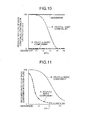
- FIG. 11 is a diagram illustrating a relation between a pH and the recovery ratio of each volatile basic component contained in acid treatment fluid.
- a predetermined acid is added so that a pH is a reference value (0) as illustrated in FIG. 11
- most of the volatile basic components (gas components) A and B are present in the acid treatment fluid as illustrated in FIG. 11 .
- the volatile basic component (gas component) B remains in the acid treatment fluid and the volatile basic component (gas component) A is separated as a gas as illustrated in FIG. 11 .
- the volatile basic component (gas component) A is ammonia or the like
- the volatile basic component (gas component) A is introduced into the absorber 13 through the gas inlet line L 4 and is discharged to the outside when there is no ammonia regulation.
- the acid 29 is added so that the volatile basic component of which the pH is equal to or lower than a reference on the acid side is not discharged to the gas component 24.
- an alkali is added to the first gas-liquid separation unit 22A, it is not possible to return the concentrated fluid 23 to the CO 2 absorbent 12 as it is as in the first embodiment.
- the reason for this is as follows: since a pH becomes high by the addition of an alkali so as to be on an alkali side, the added alkali is accumulated in absorbent 12 and causes the fluctuation of a Ph balance when the concentrated fluid returns to the absorber 13 as it is.
- a sub-regeneration unit 38 is provided, an alkali 32 is further added to the concentrated fluid 23 so that a pH of the concentrated fluid 23 is on a strong alkali side, and heat exchange is indirectly performed using saturated steam (not illustrated) in this strong alkali condition to regenerate the concentrated fluid 23, so that the CO 2 absorbent 12 is gasified.
- the gasified CO 2 absorbent is separated into the gas component 24, which contains steam, and the CO 2 absorbent 12 by a second gas-liquid separation unit 39.
- the separated CO 2 absorbent 12 returns to the upstream side of the washing unit 13B (the CO 2 absorption unit 13A) through a supply line L 10 .
- the gas component 24 such as steam returns to the top portion 13C through a supply line L 11 .
- FIG. 5 is a schematic diagram of another CO 2 recovery device according to the second embodiment.
- the washing unit 13B of the absorber 13 has included one stage.
- a washing unit includes two stages, that is, a washing unit (lower stage) 13B 1 and a washing unit (upper stage) 13B 2 .
- the washing unit is not limited to two stages and may include three or more stages.
- the CO 2 absorbent 12 in the case of this embodiment returns to a washing unit 13B 1 , which is provided on the lower stage, through the supply line L 10 .
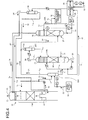
- FIG. 6 is a schematic diagram of a CO 2 recovery device according to a third embodiment.
- the same elements as the elements of the CO 2 recovery devices 10A, 10B, and 10C according to the first embodiment illustrated in FIGS. 1 , 3 , and 5 are denoted by the same reference numerals, and the repeated description thereof will not be made.
- an acid fluid 37 is supplied to a circulation line L 1 of a washing unit (upper stage) 13B 2 from an acid fluid supply unit 36, so that the wash water 20 becomes acidic. Since the wash water 20 becomes acidic, the degree of absorption of the CO 2 absorbent in the washing unit is improved.
- the alkali 32 is supplied to the extracted fluid 21 so that the extracted fluid 21 is isolated to be free from ions. As a result, the volatile basic component is easily gasified.
- an absorbent gas state
- an accompanying gas component 24 is separated by a second gas-liquid separation unit 39, returns to the absorber 13 as a regenerated absorbent, and is supplied for reuse.
- the gas component 24 is supplied to an acid washing line through a supply line L 4E with which a supply line L 4F through which the gas component 24 separated by the first gas-liquid separation unit 22A is supplied and a supply line L 4B for a gas separated by the separation drum 22C are united.
- the gasified gas of the CO 2 absorbent 12 supplied from the sub-regeneration unit 38 is sent to the second gas-liquid separation unit 39 through a supply line L 9 .
- the gas component 24 returns to a top portion of the washing unit 13B 2 through a supply line L 4 , and the regenerated CO 2 absorbent 12 returns to a first washing unit (lower stage) 13B 1 through a supply line L 10 .
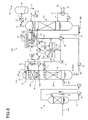
- FIG. 8 is a schematic diagram of a CO 2 recovery device according to a fourth embodiment.
- the same elements as the elements of the CO 2 recovery devices 10A, 10B, and 10C according to the first embodiment illustrated in FIGS. 1 , 3 , and 5 are denoted by the same reference numerals, and the repeated description thereof will not be made.
- steam 35 is supplied to the concentrator 22B of the second embodiment instead of the air 31 so that the ejection of the gas component 24 is performed by the steam 35.
- a return destination of the gas component 24 is not the absorber 13 unlike in the second embodiment and the gas component 24 is introduced into a top portion 14A of the regenerator 14.
- the reason for this is that the air 31 is mixed to recovered CO 2 if the regenerator 14 is used as the return destination of the gas component 24 when the air 31 is used as in the second embodiment.
- the mixing of the air 31 is the mixing of an impurity in regard to the recovered CO 2 , the purity of the recovered CO 2 is lowered.
- the steam 35 when used instead of the air 31, this purity is not lowered. Accordingly, the steam 35 may be introduced into the regenerator 14.
Landscapes
- Chemical & Material Sciences (AREA)
- Chemical Kinetics & Catalysis (AREA)
- Engineering & Computer Science (AREA)
- Analytical Chemistry (AREA)
- General Chemical & Material Sciences (AREA)
- Oil, Petroleum & Natural Gas (AREA)
- Organic Chemistry (AREA)
- Inorganic Chemistry (AREA)
- Treating Waste Gases (AREA)
- Gas Separation By Absorption (AREA)
- Physical Water Treatments (AREA)
- Carbon And Carbon Compounds (AREA)
Applications Claiming Priority (2)
| Application Number | Priority Date | Filing Date | Title |
|---|---|---|---|
| JP2011107695A JP2012236166A (ja) | 2011-05-12 | 2011-05-12 | Co2回収装置およびco2回収方法 |
| PCT/JP2012/062035 WO2012153812A1 (ja) | 2011-05-12 | 2012-05-10 | Co2回収装置およびco2回収方法 |
Publications (1)
| Publication Number | Publication Date |
|---|---|
| EP2719441A1 true EP2719441A1 (en) | 2014-04-16 |
Family
ID=47139287
Family Applications (1)
| Application Number | Title | Priority Date | Filing Date |
|---|---|---|---|
| EP12782974.5A Withdrawn EP2719441A1 (en) | 2011-05-12 | 2012-05-10 | Co2 recovery device, and co2 recovery method. |
Country Status (6)
Cited By (1)
| Publication number | Priority date | Publication date | Assignee | Title |
|---|---|---|---|---|
| CN103521053A (zh) * | 2013-09-27 | 2014-01-22 | 华中农业大学 | 基于吸收剂浓度变换的气体中co2化学吸收系统与方法 |
Families Citing this family (31)
| Publication number | Priority date | Publication date | Assignee | Title |
|---|---|---|---|---|
| JP2013059726A (ja) * | 2011-09-13 | 2013-04-04 | Mitsubishi Heavy Ind Ltd | Co2回収装置およびco2回収方法 |
| JP5738137B2 (ja) * | 2011-09-13 | 2015-06-17 | 三菱重工業株式会社 | Co2回収装置およびco2回収方法 |
| WO2013169853A1 (en) * | 2012-05-09 | 2013-11-14 | Industries Llc Yknots | Device, method, and graphical user interface for providing tactile feedback for operations performed in a user interface |
| JP6004821B2 (ja) | 2012-08-08 | 2016-10-12 | 三菱重工業株式会社 | Co2回収装置およびco2回収方法 |
| JP6016513B2 (ja) * | 2012-08-09 | 2016-10-26 | 三菱重工業株式会社 | Co2回収装置およびco2回収方法 |
| US9623366B2 (en) | 2013-03-04 | 2017-04-18 | Mitsubishi Heavy Industries, Ltd. | CO2 recovery system and CO2 recovery method |
| CN103638775A (zh) * | 2013-12-09 | 2014-03-19 | 深圳市芭田生态工程股份有限公司 | 一种含氟氨水蒸汽处理方法 |
| CN104941419A (zh) * | 2014-03-31 | 2015-09-30 | 英尼奥斯欧洲股份公司 | 反应器流出物的改进的氨移除 |
| AU2015298710B2 (en) | 2014-08-02 | 2019-10-17 | Apple Inc. | Context-specific user interfaces |
| US10452253B2 (en) | 2014-08-15 | 2019-10-22 | Apple Inc. | Weather user interface |
| WO2016068698A1 (en) | 2014-10-27 | 2016-05-06 | Carbonoro B.V. | Process and apparatus for separating entrained amines from a gas stream |
| WO2016068699A1 (en) | 2014-10-27 | 2016-05-06 | Carbonoro B.V. | Process and apparatus for separating entrained amines from a gas stream |
| WO2016144385A1 (en) | 2015-03-08 | 2016-09-15 | Apple Inc. | Sharing user-configurable graphical constructs |
| US10304347B2 (en) | 2015-08-20 | 2019-05-28 | Apple Inc. | Exercised-based watch face and complications |
| EP3181540B1 (de) * | 2015-12-18 | 2019-07-24 | L'Air Liquide Société Anonyme pour l'Etude et l'Exploitation des Procédés Georges Claude | Verfahren zur trennung von methanol aus gasgemischen |
| US12175065B2 (en) | 2016-06-10 | 2024-12-24 | Apple Inc. | Context-specific user interfaces for relocating one or more complications in a watch or clock interface |
| US10467912B2 (en) * | 2017-03-14 | 2019-11-05 | Honeywell International Inc. | System and method to revise vertical profile of a flight plan |
| DK179412B1 (en) | 2017-05-12 | 2018-06-06 | Apple Inc | Context-Specific User Interfaces |
| US11819777B2 (en) | 2017-08-22 | 2023-11-21 | Saudi Arabian Oil Company | Systems and methods for enhancing amine agent recovery with a reclaimer |
| JP7136577B2 (ja) * | 2018-03-30 | 2022-09-13 | Ube三菱セメント株式会社 | 二酸化炭素製造装置、二酸化炭素製造方法、二酸化炭素製造装置の設計方法 |
| US11327650B2 (en) | 2018-05-07 | 2022-05-10 | Apple Inc. | User interfaces having a collection of complications |
| US11260336B2 (en) * | 2018-12-20 | 2022-03-01 | Entegris, Inc. | Active wet scrubbing filtration system |
| AU2020239670B2 (en) | 2019-05-06 | 2021-07-15 | Apple Inc. | Restricted operation of an electronic device |
| US10878782B1 (en) | 2019-09-09 | 2020-12-29 | Apple Inc. | Techniques for managing display usage |
| DK202070624A1 (en) | 2020-05-11 | 2022-01-04 | Apple Inc | User interfaces related to time |
| WO2021231345A1 (en) | 2020-05-11 | 2021-11-18 | Apple Inc. | User interfaces for managing user interface sharing |
| US11694590B2 (en) | 2020-12-21 | 2023-07-04 | Apple Inc. | Dynamic user interface with time indicator |
| US11720239B2 (en) | 2021-01-07 | 2023-08-08 | Apple Inc. | Techniques for user interfaces related to an event |
| US12182373B2 (en) | 2021-04-27 | 2024-12-31 | Apple Inc. | Techniques for managing display usage |
| US11921992B2 (en) | 2021-05-14 | 2024-03-05 | Apple Inc. | User interfaces related to time |
| US20230236547A1 (en) | 2022-01-24 | 2023-07-27 | Apple Inc. | User interfaces for indicating time |
Family Cites Families (6)
| Publication number | Priority date | Publication date | Assignee | Title |
|---|---|---|---|---|
| JP2539103B2 (ja) | 1991-03-07 | 1996-10-02 | 三菱重工業株式会社 | 燃焼排ガスの脱炭酸ガス装置及び方法 |
| JP2786562B2 (ja) * | 1992-03-03 | 1998-08-13 | 関西電力株式会社 | 燃焼排ガスの処理方法 |
| JP3969949B2 (ja) * | 2000-10-25 | 2007-09-05 | 関西電力株式会社 | アミン回収方法及び装置並びにこれを備えた脱炭酸ガス装置 |
| US7981196B2 (en) * | 2007-06-04 | 2011-07-19 | Posco | Apparatus and method for recovering carbon dioxide from flue gas using ammonia water |
| NO332812B1 (no) * | 2009-03-13 | 2013-01-21 | Aker Clean Carbon As | Amin utslippskontroll |
| JP2010253370A (ja) * | 2009-04-23 | 2010-11-11 | Mitsubishi Heavy Ind Ltd | Co2回収装置及びco2回収方法 |
-
2011
- 2011-05-12 JP JP2011107695A patent/JP2012236166A/ja not_active Ceased
-
2012
- 2012-05-10 WO PCT/JP2012/062035 patent/WO2012153812A1/ja active Application Filing
- 2012-05-10 EP EP12782974.5A patent/EP2719441A1/en not_active Withdrawn
- 2012-05-10 AU AU2012254506A patent/AU2012254506A1/en not_active Abandoned
- 2012-05-10 CA CA2834667A patent/CA2834667A1/en not_active Abandoned
- 2012-05-10 US US14/005,970 patent/US20140013945A1/en not_active Abandoned
Non-Patent Citations (1)
| Title |
|---|
| See references of WO2012153812A1 * |
Cited By (2)
| Publication number | Priority date | Publication date | Assignee | Title |
|---|---|---|---|---|
| CN103521053A (zh) * | 2013-09-27 | 2014-01-22 | 华中农业大学 | 基于吸收剂浓度变换的气体中co2化学吸收系统与方法 |
| CN103521053B (zh) * | 2013-09-27 | 2015-07-29 | 华中农业大学 | 基于吸收剂浓度变换的气体中co2化学吸收系统与方法 |
Also Published As
| Publication number | Publication date |
|---|---|
| JP2012236166A (ja) | 2012-12-06 |
| WO2012153812A1 (ja) | 2012-11-15 |
| AU2012254506A1 (en) | 2013-10-17 |
| US20140013945A1 (en) | 2014-01-16 |
| CA2834667A1 (en) | 2012-11-15 |
Similar Documents
| Publication | Publication Date | Title |
|---|---|---|
| EP2719441A1 (en) | Co2 recovery device, and co2 recovery method. | |
| US9568193B2 (en) | Air pollution control system and air pollution control method | |
| EP2886183B1 (en) | Co2 recovery method with recovery of aldehydes | |
| US9901873B2 (en) | CO2 recovery device and CO2 recovery method | |
| US8420037B2 (en) | Air pollution control system and air pollution control method | |
| EP2767327A1 (en) | Co2 recovery device and co2 recovery method | |
| AU2005230300A1 (en) | Apparatus and method for recovering CO2 | |
| EP2767328A1 (en) | Co2 recovery device and co2 recovery method | |
| US9914088B2 (en) | CO2 recovery unit and CO2 recovery method | |
| US10835863B2 (en) | CO2 recovery device and CO2 recovery method | |
| US9399189B2 (en) | CO2 recovery device |
Legal Events
| Date | Code | Title | Description |
|---|---|---|---|
| PUAI | Public reference made under article 153(3) epc to a published international application that has entered the european phase |
Free format text: ORIGINAL CODE: 0009012 |
|
| 17P | Request for examination filed |
Effective date: 20131028 |
|
| AK | Designated contracting states |
Kind code of ref document: A1 Designated state(s): AL AT BE BG CH CY CZ DE DK EE ES FI FR GB GR HR HU IE IS IT LI LT LU LV MC MK MT NL NO PL PT RO RS SE SI SK SM TR |
|
| DAX | Request for extension of the european patent (deleted) | ||
| STAA | Information on the status of an ep patent application or granted ep patent |
Free format text: STATUS: THE APPLICATION HAS BEEN WITHDRAWN |
|
| 18W | Application withdrawn |
Effective date: 20140812 |