WO2012153753A1 - 消耗材の自動供給システム - Google Patents
消耗材の自動供給システム Download PDFInfo
- Publication number
- WO2012153753A1 WO2012153753A1 PCT/JP2012/061824 JP2012061824W WO2012153753A1 WO 2012153753 A1 WO2012153753 A1 WO 2012153753A1 JP 2012061824 W JP2012061824 W JP 2012061824W WO 2012153753 A1 WO2012153753 A1 WO 2012153753A1
- Authority
- WO
- WIPO (PCT)
- Prior art keywords
- vehicle
- fuel
- transport vehicle
- load
- loaded
- Prior art date
- Legal status (The legal status is an assumption and is not a legal conclusion. Google has not performed a legal analysis and makes no representation as to the accuracy of the status listed.)
- Ceased
Links
Images



Classifications
-
- B—PERFORMING OPERATIONS; TRANSPORTING
- B67—OPENING, CLOSING OR CLEANING BOTTLES, JARS OR SIMILAR CONTAINERS; LIQUID HANDLING
- B67D—DISPENSING, DELIVERING OR TRANSFERRING LIQUIDS, NOT OTHERWISE PROVIDED FOR
- B67D7/00—Apparatus or devices for transferring liquids from bulk storage containers or reservoirs into vehicles or into portable containers, e.g. for retail sale purposes
- B67D7/06—Details or accessories
- B67D7/32—Arrangements of safety or warning devices; Means for preventing unauthorised delivery of liquid
- B67D7/34—Means for preventing unauthorised delivery of liquid
- B67D7/344—Means for preventing unauthorised delivery of liquid by checking a correct coupling or coded information
- B67D7/348—Means for preventing unauthorised delivery of liquid by checking a correct coupling or coded information by interrogating an information transmitter, e.g. a transponder
-
- B—PERFORMING OPERATIONS; TRANSPORTING
- B67—OPENING, CLOSING OR CLEANING BOTTLES, JARS OR SIMILAR CONTAINERS; LIQUID HANDLING
- B67D—DISPENSING, DELIVERING OR TRANSFERRING LIQUIDS, NOT OTHERWISE PROVIDED FOR
- B67D7/00—Apparatus or devices for transferring liquids from bulk storage containers or reservoirs into vehicles or into portable containers, e.g. for retail sale purposes
- B67D7/06—Details or accessories
- B67D7/32—Arrangements of safety or warning devices; Means for preventing unauthorised delivery of liquid
Definitions
- the present invention relates to an automatic supply system for consumable materials that automatically supplies consumable materials such as fuel and oil to a vehicle.
- an automatic supply system for consumables a fuel supply port of a vehicle fuel tank provided in a vehicle is detected by a camera, and a manipulator that holds the nozzle is controlled based on the detection position of the fuel supply port to supply the nozzle.
- An automatic fueling device that is inserted into a mouth is known (for example, see Patent Document 1). In such an automatic fueling device, when the vehicle stops near the automatic fueling device, the automatic fueling is started.
- a dump truck that can load a load such as a rock or earth used in a mine.
- the load may drop during the fuel supply. If the load falls during fuel supply, the dropped load may damage the automatic fueling device or incidental equipment.
- an object of the present invention is to provide an automatic supply system for consumable materials that can suppress the fall of a load from a vehicle during automatic supply of consumable materials.
- the automatic supply system for consumables acquires an automatic supply device that automatically supplies consumables to a vehicle capable of loading a load, and loading information that is information on whether or not the load is loaded on the vehicle. And a control device capable of controlling the automatic supply of consumables to the vehicle based on the loaded information. When the control device determines from the acquired loading information that the load is loaded on the vehicle, the automatic supply The apparatus does not automatically supply the consumable material to the vehicle.
- the load detection means is a load amount detection means for detecting the load amount of the load loaded on the vehicle, It is preferable to have at least one of an imaging unit that images a load loaded on the vehicle and a vehicle weight measurement unit that measures the weight of the vehicle.
- a notification means for notifying that a load is loaded on the vehicle.
- the vehicle has a vessel on which a load can be loaded, and the automatic supply device is located on the lower side in the vertical direction of the vessel and inside the edge of the vessel in plan view from the vertical direction. It is preferable to automatically supply the consumable material to the container.
- Another consumable material automatic supply system of the present invention includes an automatic supply device that automatically supplies consumable materials to a vehicle having a vessel on which a load can be loaded, and a control device that can control the automatic supply device.
- the apparatus is characterized in that the consumable material is automatically supplied to the vehicle in a range below the vessel in the vertical direction and inside the edge of the vessel in plan view from the vertical direction.
- the consumable material automatic supply system of the present invention when a load is loaded on the vehicle, the supply of consumable materials such as fuel and oil is not performed. Etc. can be suppressed.
- FIG. 1 is a schematic configuration diagram schematically illustrating a trolley transport system to which the consumable material automatic supply system according to the first embodiment is applied.
- FIG. 2 is a block diagram showing the configuration of the automatic supply system.
- FIG. 3 is a plan view schematically showing a part of the transport vehicle.
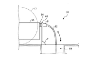
- FIG. 4 is a side view schematically showing a part of the fuel supply device.
- FIG. 5 is a flowchart regarding the control operation of the automatic supply system.
- the automatic supply system for consumables in Example 1 is applied to a trolley transport system.
- This trolley transport system is mounted on a transport vehicle while power is supplied to the transport vehicle by bringing the pantograph in contact with a trolley wire to which power is supplied, and the supplied power is used as auxiliary power for the transport vehicle. It is a system that transports the loaded cargo.
- FIG. 1 is a schematic configuration diagram schematically illustrating a trolley transport system to which the consumable material automatic supply system according to the first embodiment is applied.
- this trolley transport system 1 is used in a mine or the like, and includes a transport vehicle 5, a power supply facility 6, a fuel supply facility 7, and a central management control facility 8 that manages and controls them. ing.
- the transport vehicle 5 is a dump truck with a trolley assist function having a so-called pantograph, and can run unattended.
- Example 1 demonstrates as the transport vehicle 5 which can drive
- the transport vehicle 5 includes a vehicle main body 11, a vessel 12, a pantograph 13, a communication unit 14, a position detection unit 15, and a control unit 16.
- the vehicle body 11 is a vehicle that generates power using fuel in the engine and generates power using electric power in the motor, and can travel by transmitting the generated power to the drive wheels 17. Yes.
- the vessel 12 is used to load a load and is disposed on the upper portion of the vehicle body 11.
- the vessel 12 is loaded with soil, such as rocks and soil, as luggage.
- the vessel 12 may be configured to be detachable from the vehicle body 11.
- the pantograph 13 functions as a current collector, and is disposed on the front side of the traveling direction of the vehicle body 11 so as to be positioned at the top of the transport vehicle 5.
- the communication unit 14 is connected to the control unit 16 and performs wireless communication between the control unit 16 of the transport vehicle 5 and the central management control facility 8.
- the communication unit 14 acquires information transmitted from the central management control facility 8 and outputs the information to the control unit 16, acquires information output from the control unit 16, and outputs the information to the central control facility 8.
- the position detection unit 15 uses, for example, a GPS (Global Positioning System) and recognizes the position of the transport vehicle 5.
- the position detection unit 15 is connected to the control unit 16 and outputs the detected position information to the control unit 16.
- the control part 16 controls operation
- the transport vehicle 5 configured in this manner transports a load along a predetermined travel route while being controlled by the control unit 15. Specifically, the transport vehicle 5 reciprocates between a loading site 18 on which loads are loaded and an earth discharge site (unloading site) 19 on which loads are loaded. Further, the transport vehicle 5 travels toward the fuel supply facility 7 while being controlled by the control unit 15 when the fuel is consumed and the remaining amount of fuel is reduced.
- the power supply facility 6 has a trolley wire 21 to which power is supplied from a power source (not shown).
- the trolley line 21 is disposed in a predetermined section of the travel route on which the transport vehicle 5 travels, and is provided above the transport vehicle 5.
- the trolley line 21 is provided as a predetermined section, for example, in a climbing section. For this reason, the power supply facility 6 supplies power to the transport vehicle 5 via the pantograph 13 that contacts the trolley wire 21 as auxiliary power for the transport vehicle 5 that performs climbing travel.
- the fueling facility 7 includes a fuel supply device 31, a communication unit 32, and a control unit 33.
- the fuel supply device 31 supplies fuel to the transport vehicle 5 that has entered the fuel supply facility 7.
- the communication unit 32 is connected to the control unit 33, performs wireless communication between the control unit 33 of the fueling facility 7 and the central management control facility 8, and transmits and receives various types of information.
- the control unit 33 controls the operation of each unit of the fuel supply device 31 based on the acquired various information, or transmits the acquired various information to the central management control facility 8 via the communication unit 32. Yes.
- the fuel supply apparatus 31 comprises a part of automatic supply system 50, and becomes a structure which can supply fuel to the conveyance vehicle 5 automatically.
- the central management control facility 8 is provided in a different place from the transport vehicle 5, the power supply facility 6, and the fuel supply facility 7, and includes a management controller 41 and a communication unit 42.
- the communication unit 42 performs wireless communication between the transport vehicle 5 and the fuel supply facility 7 and the management controller 41, and transmits and receives various types of information.
- the management controller 41 is operated by an operator based on various information acquired through the communication unit 42. Specifically, the management controller 41 recognizes the position of the transport vehicle 5, manages the driving status of the transport vehicle 5, and controls the operation of the transport vehicle 5 based on various information transmitted from the transport vehicle 5. I do. Similarly, the management controller 41 manages the operation status of the fueling facility 7 and controls the operation of the fueling facility 7 based on various information transmitted from the fueling facility 7.
- the operation status of the transport vehicle 5 is managed by the central management control facility 8, and the operation of the transport vehicle 5 is controlled based on the managed drive status of the transport vehicle 5. That is, in the trolley transport system 1, various information is transmitted from the central management control facility 8 to the control unit 15 of the transport vehicle 5 via the communication unit 42 and the communication unit 14 based on the driving situation of the transport vehicle 5. Thus, the operation of the transport vehicle 5 is controlled. For this reason, when the transport vehicle 5 travels in the climbing section, the transport vehicle 5 brings the pantograph 13 into contact with the trolley wire 21 of the power supply facility 6 and uses the power supplied from the trolley wire 21 as auxiliary power, It is possible to travel on the travel route between 18 and the earth removal site 19. In addition, when the fuel of the transport vehicle 5 is consumed and the remaining amount of fuel decreases, the transport vehicle 5 can travel toward the fuel supply facility 7.
- FIG. 2 is a block diagram showing the configuration of the automatic supply system
- FIG. 3 is a plan view schematically showing a part of the transport vehicle
- FIG. 4 is a schematic view showing a part of the fuel supply apparatus.
- FIG. The trolley driving system 1 configured as described above incorporates an automatic consumable supply system 50 that supplies consumables to the transport vehicle 5.
- Consumables include fuel, oil used for lubrication and hydraulic control, and grease used for lubrication.
- Example 1 the case where it is applied to fuel as a consumable material will be described.
- the automatic supply system 50 automatically supplies fuel from the fuel supply device (automatic supply device) 31 of the fuel supply facility 7 to the transport vehicle 5 that can load a load.
- the automatic supply system 50 includes the transport vehicle (vehicle) 5 described above, the fuel supply facility 7 described above, and the central management control facility (control device) 8 described above.
- the automatic supply system 50 also includes a payload meter (mounting amount detection means) 51 that detects the load amount of the load loaded on the transport vehicle 5, and a fuel meter 52 that detects the remaining fuel of the transport vehicle 5.
- the payload meter 51 and the fuel meter 52 are provided in the transport vehicle 5.
- the payload meter 51 detects the load amount of the load loaded on the transport vehicle 5 based on the detected pressure of the pressure sensor that detects the pressure of the suspension that supports the drive wheels 17 of the vehicle body 11.
- the payload meter 51 is connected to the control unit 16 and outputs the detected loading amount to the control unit 16 as loading information.
- the control unit 16 transmits the input loading information to the central management control facility 8 through the communication unit 14 and the communication unit 42.
- the fuel gauge 52 measures the remaining amount of fuel accumulated in the fuel tank 55 provided in the vehicle main body 11.
- the fuel gauge 52 is connected to the control unit 16 and outputs the detected remaining amount of fuel to the control unit 16 as supply information.
- the control unit 16 transmits the input supply information to the central management control facility 8 via the communication unit 14 and the communication unit 42.
- the central management control facility 8 inputs supply information and loading information to the management controller 41 via the communication unit 42.
- the management controller 41 acquires the input supply information
- the management controller 41 determines whether to supply fuel to the transport vehicle 5 based on the acquired supply information.
- the management controller 41 acquires the input loading information
- the management controller 41 determines whether or not a load is loaded on the transport vehicle 5 based on the acquired loading information.
- the management controller 41 determines that fuel is to be supplied to the transport vehicle 5 from the acquired supply information, if the load is loaded on the transport vehicle 5 from the acquired loading information, the automatic fuel control is performed. While the fuel supply device 31 does not supply the fuel, the fuel supply device 31 performs the automatic fuel supply when no load is loaded on the transport vehicle 5.
- the fuel supply device 31 automatically supplies fuel to a fuel tank 55 provided in the vehicle body 11 of the transport vehicle 5.
- the fuel tank 55 is provided on the rear side in the traveling direction of the transport vehicle 5, and the fuel tank 55 is provided with a fuel filler port 56.
- the fuel filler port 56 is provided on the outer side surface of the fuel tank 55, and is disposed in a range E on the lower side in the vertical direction of the vessel 12 and inside the edge portion 12 a of the vessel 12 in plan view from the vertical direction. .
- one fuel tank 55 is provided on the rear side in the traveling direction.
- the fuel tank 55 may be provided on the front side in the traveling direction, and the arrangement position is not limited.
- the fuel supply device 31 includes a supply nozzle 61 attached to the fuel supply port 56, a fuel hose 62 connected to the supply nozzle 61, and a movable plate 63 that moves the supply nozzle 61. And a storage portion 64 for storing the supply nozzle 61 and the fuel hose 62.
- One end of the movable plate 63 is connected to the rotation shaft T, while the other end is a free end. For this reason, the movable plate 63 moves between the horizontal state and the vertical state around the rotation axis T.
- the storage unit 64 is formed below the ground of the fuel supply facility 7 and stores the supply nozzle 61 and the fuel hose 62.
- the movable plate 63 serves as a lid of the storage unit 64 and closes the storage unit 64 in the horizontal state, while opening the storage unit 64 in the vertical state.
- the supply nozzle 61 is fixed to the free end side of the movable plate 63. For this reason, when the movable plate 63 is in the vertical state, the supply nozzle 61 is exposed from the storage portion 64, and the fuel supply port 56 and the supply nozzle 61 are connected in the horizontal direction, so that the supply nozzle 61 is connected to the fuel supply port of the fuel tank 55. 56. At the same time, the fuel hose 62 connected to the supply nozzle 61 is pulled out from the storage portion 64.
- the supply nozzle 61 is removed from the fuel supply port 56 of the fuel tank 55, the supply nozzle 61 is stored in the storage portion 64, and the fuel hose 62 connected to the supply nozzle 61. Is stored in the storage unit 64.
- the fuel supply device 31 is provided at a position on the rear side of the transport vehicle 5.
- the fuel supply device 31 is provided at a position on the front side or the side side of the transport vehicle 5. The fuel may be supplied from the front side or the side side of the transport vehicle 5.
- the fuel supply device 31 automatically supplies the transport vehicle 5. That is, the fuel supply device 31 rotates the movable plate 63 from the horizontal state to the vertical state around the rotation axis T, and attaches the supply nozzle 61 to the fuel supply port 56. When the supply nozzle 61 is attached to the fuel supply port 56, the fuel supply device 31 starts supplying fuel. At this time, the fuel supply device 31 can supply fuel within the range E because the fuel supply port 56 of the fuel tank 55 is within the range E.
- the fuel supply device 31 rotates the movable plate 63 from the vertical state to the horizontal state around the rotation shaft T, and removes the supply nozzle 61 from the fuel supply port 56. Then, the automatic fuel supply is terminated.
- the fuel supply device 31 does not rotate the movable plate 63, so the supply nozzle 61 is not attached to the fuel supply port 56.
- the movable plate 63 is rotated from the horizontal state to the vertical state around the rotation axis T, and the supply nozzle 61 is moved to the fuel supply port 56. After mounting, the fuel supply device 31 may not supply fuel.
- a camera is provided in the fuel supply facility 7, the position of the fuel supply port 56 of the fuel tank 55 of the transport vehicle 5 is detected by the camera, and the fuel supply port 56 detected by the camera is detected.
- the supply nozzle 61 may be mounted based on the detection position.
- the movable plate 63 may be configured to be movable so that the supply nozzle 61 is movable. That is, the control unit 33 of the fuel supply facility 7 adjusts the position of the supply nozzle 61 with respect to the fuel supply port 56 by controlling the position of the movable plate 63 based on the detection position of the fuel supply port 56 detected by the camera. Thereby, in the fuel supply facility 7, the supply nozzle 61 can be accurately attached to the fuel supply port 56.
- FIG. 5 is a flowchart regarding the control operation of the automatic supply system.
- the control operation of the automatic supply system 50 configured as described above will be described with reference to FIG.
- the supply information detected by the fuel gauge 52 and the loading information detected by the payload meter 51 are transmitted from the transport vehicle 5 to the central management control facility 8, and the management controller 41 acquires the transmitted supply information and loading information. .
- the management controller 41 determines whether fuel is supplied to the transport vehicle 5 based on the acquired supply information (step S1).
- step S1 determines from the acquired supply information that fuel is to be supplied to the transport vehicle 5 (step S1: Yes)
- step S1 determines with the management controller 41 not supplying fuel to the conveyance vehicle 5 from the acquired supply information (step S1: No)
- step S1 determines with the management controller 41 not supplying fuel to the conveyance vehicle 5 from the acquired supply information
- Step S2 When the management controller 41 determines from the acquired loading information that the transport vehicle 5 is loaded with a load (Step S2: Yes), the fuel supply device 31 does not automatically supply the transport vehicle 5 with fuel. Then, automatic fueling by the fuel supply device 31 is prohibited (step S6). And management controller 41 progresses to Step S2 after execution of Step S6, and repeats Step S6 and Step S2 until the load of transportation vehicle 5 is unloaded.
- step S2 When the management controller 41 determines in step S2 from the acquired loading information that the transport vehicle 5 is not loaded (step S2: No), the fuel supply device 31 automatically supplies fuel to the transport vehicle 5. Automatic fueling by the fuel supply device 31 is permitted (step S3). Thereafter, when the transport vehicle 5 enters the fuel supply facility 7 and stops at a position where fuel can be supplied by the fuel supply device 31, the transport vehicle 5 stops the engine (step S4). And the fuel supply apparatus 31 performs automatic supply with respect to the transport vehicle 5 (step S5). That is, the fuel supply device 31 rotates the movable plate 63 of the fuel supply device 31 of the fuel supply facility 7 around the rotation axis T, attaches the supply nozzle 61 to the fuel supply port 56 of the fuel tank 55, and supplies fuel. To do. The transport vehicle 5 transmits an engine stop signal to the fuel supply facility 7 when the engine is stopped, and the fuel supply facility 7 executes automatic fuel supply after receiving the stop signal transmitted from the transport vehicle 5. It is preferable.
- the management controller 41 does not automatically supply fuel by the fuel supply device 31 when a load is loaded on the transport vehicle 5. Thereby, since the fuel can be automatically supplied in a state in which no load is loaded on the transport vehicle 5, it is possible to suppress the fall of the load at the time of supplying the fuel, and damage of the fuel supply facility 7 due to the fall of the load. Can be reduced.
- the management controller 41 can determine whether or not a load is loaded on the transport vehicle 5 based on the load amount of the load detected by the payload meter 51. For this reason, the existing payload meter 51 provided in the transport vehicle 5 can be utilized.
- the management controller 41 determines whether or not to supply fuel to the transport vehicle 5 based on the remaining amount of fuel detected by the fuel gauge 52 (step S1). Can do. For this reason, the existing fuel gauge 52 provided in the transport vehicle 5 can be utilized. Note that, in addition to this configuration, when the transport vehicle 5 is a dump truck that can be traveled by manned, it may be determined by the driver whether fuel is supplied to the transport vehicle 5 or not. That is, in the automatic supply system for consumable materials according to the first embodiment, the configuration of step S1 is not essential.
- the fuel supply device 31 can automatically supply the fuel within the range E. Therefore, the fuel supply device 31 does not receive the interference of the load falling from the vessel 12, and the fuel due to the fall of the load. Damage to the supply device 31 can be reduced.
- an automatic supply system for consumable materials according to the second embodiment.
- the second embodiment only parts different from the first embodiment will be described in order to avoid redundant description.
- the first embodiment it is determined whether or not the automatic refueling is performed by the management controller 41.
- the second embodiment it is determined whether or not the automatic refueling is performed by the control unit (control device) 33 of the refueling facility 7. . That is, in the second embodiment, it is possible to determine whether or not to perform automatic refueling without using the management controller 41 of the central management control facility 8.
- the configuration of the central management control facility 8 is not essential in the automatic consumable supply system of the second embodiment.
- the transport vehicle 5 transmits the loading information detected by the payload meter 51 toward the fuel supply facility 7 via the communication unit 14 and the communication unit 32.
- the loading information is input to the control unit 33 via the communication unit 32.
- the control unit 33 determines whether or not a load is loaded on the transport vehicle 5 based on the acquired loading information.
- control operation of the automatic supply system of the second embodiment will be briefly described.
- the control operation of the automatic supply system according to the second embodiment has substantially the same configuration as the control operation of the automatic supply system 50 according to the first embodiment, and therefore only different parts will be described with reference to FIG.
- the loading information detected by the payload meter 51 is transmitted from the transport vehicle 5 to the fueling facility 7, and the control unit 33 of the fueling facility 7 acquires the transmitted loading information. Then, the control unit 33 of the fueling facility 7 determines whether or not a load is loaded on the transport vehicle 5 based on the acquired loading information (step S2).
- step S2 When the control unit 33 of the fuel supply facility 7 determines from the acquired loading information that the transport vehicle 5 is loaded with a load (step S2: Yes), the fuel supply device 31 performs automatic fuel supply to the transport vehicle 5. In order to prevent the fuel from being fed, automatic fueling by the fuel supply device 31 is prohibited (step S6). On the other hand, when the control unit 33 of the fuel supply facility 7 determines in step S2 that the transport vehicle 5 is not loaded with the load from the acquired loading information (step S2: No), the transport vehicle by the fuel supply device 31 is used. The automatic fuel supply by the fuel supply device 31 is permitted so that automatic fuel supply to 5 is performed (step S3).
- the control unit 33 of the fuel supply facility 7 does not automatically perform fuel supply by the fuel supply device 31 when a load is loaded on the transport vehicle 5. Thereby, since the fuel can be automatically supplied in a state in which no load is loaded on the transport vehicle 5, it is possible to suppress the fall of the load at the time of supplying the fuel, and damage of the fuel supply facility 7 due to the fall of the load. Can be reduced.
- the loading information is detected by the payload meter 51.
- the loading information may be detected by an imaging camera (imaging means). That is, an imaging camera is provided on the transport vehicle 5, and the image capture camera images the vessel 12 of the transport vehicle 5.
- the imaging camera is connected to the control unit 16 of the transport vehicle 5, and the control unit 16 transmits the loading information acquired from the imaging camera to the fuel supply facility 7 or the central management control facility 8. Then, when the refueling facility 7 or the central management control facility 8 acquires the transmitted loading information, the refueling facility 7 or the central management control facility 8 determines whether or not a load is loaded on the transport vehicle 5 based on the acquired loading information.
- the loading information is detected by the payload meter 51 provided in the transport vehicle 5, and it is determined whether the automatic refueling is performed by the management controller 41.
- whether or not automatic fueling is performed by the control unit (control device) 33 of the fueling facility 7 is detected by the vehicle weight meter (vehicle weight measuring means) provided in the fueling facility 7. Judgment.
- the configuration of the communication unit 32 of the fuel supply facility 7 is not essential.
- the vehicle weight meter provided in the fuel supply facility 7 is provided on the travel route of the transport vehicle 5 and measures the weight of the transport vehicle 5 entering the fuel supply facility 7.
- the vehicle weight meter is connected to the control unit 33 of the fuel supply facility 7, and outputs the detected vehicle weight as loading information from the vehicle weight meter to the control unit 33.
- the control unit 33 determines whether or not a load is loaded on the transport vehicle 5 based on the acquired loading information.
- control operation of the automatic supply system of the third embodiment will be briefly described. Note that the control operation of the automatic supply system according to the third embodiment has almost the same configuration as the control operation of the automatic supply system 50 according to the first embodiment, and therefore only different parts will be described with reference to FIG.
- the weight meter When the transport vehicle 5 traveling toward the fueling facility 7 gets on the weight count, the weight meter outputs the loading information to the control unit 33 of the fueling facility 7, and the output loading information is supplied to the fueling facility 7. Is acquired by the control unit 33. Then, the control unit 33 of the fueling facility 7 determines whether or not a load is loaded on the transport vehicle 5 based on the acquired loading information (step S2).
- step S2 When the control unit 33 of the fuel supply facility 7 determines from the acquired loading information that the transport vehicle 5 is loaded with a load (step S2: Yes), the fuel supply device 31 performs automatic fuel supply to the transport vehicle 5. In order to prevent the fuel from being fed, automatic fueling by the fuel supply device 31 is prohibited (step S6). On the other hand, when the control unit 33 of the fuel supply facility 7 determines in step S2 that the transport vehicle 5 is not loaded with the load from the acquired loading information (step S2: No), the transport vehicle by the fuel supply device 31 is used. The automatic fuel supply by the fuel supply device 31 is permitted so that automatic fuel supply to 5 is performed (step S3).
- the control unit 33 of the fuel supply facility 7 does not automatically perform fuel supply by the fuel supply device 31 when a load is loaded on the transport vehicle 5. Thereby, since the fuel can be automatically supplied in a state in which no load is loaded on the transport vehicle 5, it is possible to suppress the fall of the load at the time of supplying the fuel, and damage of the fuel supply facility 7 due to the fall of the load. Can be reduced.
- Example 3 since loading information can be detected using the weight meter provided in the fuel supply equipment 7, communication between the transport vehicle 5 and the central management control apparatus 8 is performed. It is not necessary, and it can be determined whether or not automatic refueling is performed in the refueling facility 7.
- the loading information is detected by the vehicle weight meter.
- the loading information may be detected by an imaging camera (imaging means). That is, an imaging camera is provided in the fueling facility 7, and the imaging camera images the vessel 12 of the transport vehicle 5 entering the fueling facility 7.
- the imaging camera is connected to the control unit 33 of the fueling facility 7 and outputs the detected image as loading information from the imaging camera to the control unit 33.
- the control unit 33 determines whether or not a load is loaded on the transport vehicle 5 based on the acquired loading information.
- the vehicle weight scale is connected to the control unit 33 of the fuel supply facility 7.
- the vehicle weight scale is separated from the fuel supply facility 7, and the vehicle weight scale transmits the detected loading information to the transport vehicle 5, You may comprise so that transmission toward the oil supply equipment 7 or the central management control equipment 8 is possible.
- or 3 applied and demonstrated to the trolley conveyance system 1 using the conveyance vehicle 5 which has the pantograph 13, it is not restricted to this structure, and the conveyance using the conveyance vehicle 5 which does not have the pantograph 13 is used. It may be applied to the system.
- a dump truck capable of unmanned traveling is applied as the transport vehicle 5, but may be applied to a dump truck capable of traveling by manned.
- a notifying means for notifying that a load is loaded on the transport vehicle 5.
- a signal device may be provided at the entrance of the fueling facility 7 and the warning signal may be displayed on the signal device, or a display monitor may be provided in the operator's cab of the transport vehicle 5 and a warning display may be displayed on the display monitor. You may let them. According to this configuration, it is possible to appropriately notify the driver who drives the transport vehicle 5 that the load is loaded on the transport vehicle 5.
- the transport vehicle 5 is described as applied to a vehicle using an engine and a motor as a power source.
- the present invention is not limited to this configuration, and the present invention may be applied to a vehicle using only an engine as a power source. Alternatively, the present invention may be applied to a vehicle that uses only a motor driven by an engine as a power source.
- the fuel gauge 52 is used to determine whether or not the fuel is supplied to the transport vehicle 5.
- the present invention is not limited to this configuration. It may be determined whether or not fuel is supplied to the transport vehicle 5 using the management controller 41 that manages the situation. Specifically, the management controller 41 manages the elapsed time from when the transport vehicle 5 supplies the previous fuel to the current time as the operation status of the transport vehicle 5. The management controller 41 determines that the fuel is supplied to the transport vehicle 5 when the elapsed time exceeds a preset set time, while the transport vehicle when the elapsed time does not exceed the preset set time. 5 is determined not to supply fuel. Also in this configuration, the management controller 41 can determine whether or not to supply fuel to the transport vehicle 5.
- the management controller 41 of the central management control facility 8 or the control unit 33 of the refueling facility 7 determines whether or not automatic refueling is performed. You may determine by the provided control part (control apparatus) 16. FIG. That is, when the control unit 16 of the transport vehicle 5 acquires the loading information, the control unit 16 may determine whether or not to perform automatic refueling, and may transmit the determination result to the control unit 33 of the fuel supply facility 7. .
- the fuel supply port 56 and the supply nozzle 61 are connected in the horizontal direction, but the supply nozzle 61 is moved from the lower side in the vertical direction to the upper side to the fuel supply port 56 positioned on the upper side in the vertical direction. May be connected. According to this configuration, since the supply nozzle 61 may be moved in the vertical direction without rotating, the attachment operation of the supply nozzle 61 can be performed within the range E, and the load falling from the vessel 12 can be removed. Interference can be further reduced.
Landscapes
- Engineering & Computer Science (AREA)
- Mechanical Engineering (AREA)
- Loading And Unloading Of Fuel Tanks Or Ships (AREA)
Abstract
Description
図1は、実施例1の消耗材の自動供給システムを適用したトロリー運搬システムを模式的に表す概略構成図である。図1に示すように、このトロリー運搬システム1は、鉱山等で用いられており、運搬車両5と、給電設備6と、給油設備7と、これらを管理制御する中央管理制御設備8とを備えている。
図2は、自動供給システムの構成を示すブロック図であり、図3は、運搬車両の一部を模式的に表した平面図であり、図4は、燃料供給装置の一部を模式的に表した側面図である。上記のように構成されたトロリー運転システム1には、運搬車両5に対し消耗材を供給する消耗材の自動供給システム50が組み込まれている。なお、消耗材としては、燃料、潤滑および油圧制御に用いられるオイルや、潤滑に用いられるグリス等がある。実施例1では、消耗材として、燃料に適用した場合について説明する。
図5は、自動供給システムの制御動作に関するフローチャートである。図5を参照して、上記のように構成した自動供給システム50の制御動作について説明する。運搬車両5から中央管理制御設備8へ向けて、燃料計52により検出した供給情報と、ペイロードメータ51により検出した積載情報が送信され、送信された供給情報および積載情報を管理コントローラ41が取得する。すると、管理コントローラ41は、取得した供給情報に基づいて、運搬車両5に燃料を供給するか否かを判定する(ステップS1)。
5 運搬車両
6 給電設備
7 給油設備
8 中央管理制御設備
11 車両本体
12 ベッセル
13 パンタグラフ
14 通信部
15 位置検出部
16 制御部
17 駆動輪
18 積荷場
19 排土場
21 トロリー線
31 燃料供給装置
32 通信部
33 制御部
41 管理コントローラ
42 通信部
50 自動供給システム
51 ペイロードメータ
52 燃料計
55 燃料タンク
56 給油口
61 供給ノズル
62 燃料ホース
63 可動板
64 格納部
T 回動軸
E 範囲
Claims (5)
- 荷物を積載可能な車両に消耗材を自動供給する自動供給装置と、
前記車両に前記荷物が積載されているか否かの情報である積載情報を取得し、取得した前記積載情報に基づいて、前記車両への前記消耗材の自動供給を制御可能な制御装置と、を備え、
前記制御装置は、
取得した前記積載情報から、前記車両に前記荷物が積載されていると判定すると、前記自動供給装置による前記車両への前記消耗材の自動供給を行なわせないことを特徴とする消耗材の自動供給システム。 - 前記車両に前記荷物が積載されているか否かを、前記積載情報として検出可能な荷物検出手段をさらに備え、
前記荷物検出手段は、前記車両に積載された荷物の搭載量を検出する搭載量検出手段、前記車両に積載された前記荷物を撮像する撮像手段、および前記車両の重量を測定する車重測定手段のうち、少なくともいずれか1つを有していることを特徴とする請求項1に記載の消耗材の自動供給システム。 - 前記車両に前記荷物が積載されている旨を報知する報知手段をさらに備えたことを特徴とする請求項1または2に記載の消耗材の自動供給システム。
- 前記車両は、前記荷物を積載可能なベッセルを有し、
前記自動供給装置は、前記ベッセルの鉛直方向における下方側で、且つ鉛直方向から平面視した前記ベッセルの縁部よりも内側となる範囲において、前記車両に前記消耗材を自動供給することを特徴とする請求項1から3のいずれか1項に記載の消耗材の自動供給システム。 - 荷物を積載可能なベッセルを有する車両に消耗材を自動供給する自動供給装置と、
前記自動供給装置を制御可能な制御装置と、を備え、
前記自動供給装置は、前記ベッセルの鉛直方向における下方側で、且つ鉛直方向から平面視した前記ベッセルの縁部よりも内側となる範囲において、前記車両に前記消耗材を自動供給することを特徴とする消耗材の自動供給システム。
Priority Applications (5)
| Application Number | Priority Date | Filing Date | Title |
|---|---|---|---|
| CA2832789A CA2832789C (en) | 2011-05-10 | 2012-05-09 | Automatic supply system of consumable material |
| US14/110,514 US10155653B2 (en) | 2011-05-10 | 2012-05-09 | Automatic supply system of consumable material |
| AU2012254547A AU2012254547B2 (en) | 2011-05-10 | 2012-05-09 | Automatic supply system for consumable material |
| CN201280017760.2A CN103459303B (zh) | 2011-05-10 | 2012-05-09 | 消耗材料的自动供给系统 |
| AU2015249203A AU2015249203B2 (en) | 2011-05-10 | 2015-10-30 | Automatic supply system for consumable material |
Applications Claiming Priority (2)
| Application Number | Priority Date | Filing Date | Title |
|---|---|---|---|
| JP2011-105746 | 2011-05-10 | ||
| JP2011105746A JP5687130B2 (ja) | 2011-05-10 | 2011-05-10 | 消耗材の自動供給システム |
Publications (1)
| Publication Number | Publication Date |
|---|---|
| WO2012153753A1 true WO2012153753A1 (ja) | 2012-11-15 |
Family
ID=47139230
Family Applications (1)
| Application Number | Title | Priority Date | Filing Date |
|---|---|---|---|
| PCT/JP2012/061824 Ceased WO2012153753A1 (ja) | 2011-05-10 | 2012-05-09 | 消耗材の自動供給システム |
Country Status (6)
| Country | Link |
|---|---|
| US (1) | US10155653B2 (ja) |
| JP (1) | JP5687130B2 (ja) |
| CN (1) | CN103459303B (ja) |
| AU (1) | AU2012254547B2 (ja) |
| CA (2) | CA2912687C (ja) |
| WO (1) | WO2012153753A1 (ja) |
Families Citing this family (5)
| Publication number | Priority date | Publication date | Assignee | Title |
|---|---|---|---|---|
| JP5687130B2 (ja) | 2011-05-10 | 2015-03-18 | 株式会社小松製作所 | 消耗材の自動供給システム |
| JP5882610B2 (ja) | 2011-06-21 | 2016-03-09 | 株式会社小松製作所 | 燃料の給油システムおよび土木機械 |
| US10063105B2 (en) | 2013-07-11 | 2018-08-28 | Energous Corporation | Proximity transmitters for wireless power charging systems |
| WO2018124144A1 (ja) * | 2016-12-28 | 2018-07-05 | 株式会社小松製作所 | 作業車両、サーバ装置、積載重量管理システムおよび積載重量管理方法 |
| US11797011B2 (en) * | 2018-02-13 | 2023-10-24 | Seiko Epson Corporation | Traveling control system for transport vehicle and traveling control method for transport vehicle |
Citations (5)
| Publication number | Priority date | Publication date | Assignee | Title |
|---|---|---|---|---|
| JPS6367296A (ja) * | 1986-09-02 | 1988-03-26 | 株式会社 富永製作所 | 給油口検出機能を備えた給油装置 |
| JPH041048U (ja) * | 1990-04-20 | 1992-01-07 | ||
| JPH0431297A (ja) * | 1990-05-22 | 1992-02-03 | Tominaga Oil Pump Mfg Co Ltd | 給油ホースの繰出し装置 |
| JPH04128187A (ja) * | 1990-09-20 | 1992-04-28 | Tokico Ltd | ロボット給油装置 |
| JPH05112396A (ja) * | 1991-10-21 | 1993-05-07 | Tokico Ltd | 自動給油装置 |
Family Cites Families (26)
| Publication number | Priority date | Publication date | Assignee | Title |
|---|---|---|---|---|
| US2756983A (en) * | 1951-03-26 | 1956-07-31 | James F Furcini | Load weighing and supporting mechanism |
| US4307300A (en) * | 1978-03-02 | 1981-12-22 | Kabushiki Kaisha Komatsu Seisakusho | Dump truck with safety circuit |
| JPS5519690A (en) * | 1979-06-12 | 1980-02-12 | Shin Meiwa Ind Co Ltd | Safety tilting device for bed of dump truck |
| US4630227A (en) * | 1984-04-27 | 1986-12-16 | Hagenbuch Roy George Le | Apparatus and method for on-board measuring of the load carried by a truck body |
| US5416706A (en) * | 1984-04-27 | 1995-05-16 | Hagenbuch; Leroy G. | Apparatus for identifying containers from which refuse is collected and compiling a historical record of the containers |
| US5327347A (en) * | 1984-04-27 | 1994-07-05 | Hagenbuch Roy George Le | Apparatus and method responsive to the on-board measuring of haulage parameters of a vehicle |
| US4981186A (en) * | 1989-10-12 | 1991-01-01 | Marathon Letourneau Company | Truck load weighing method and apparatus |
| US5383500A (en) * | 1992-03-19 | 1995-01-24 | Shell Oil Company | Automatic refuelling system |
| JP2925468B2 (ja) * | 1995-01-31 | 1999-07-28 | 株式会社小松製作所 | ダンプの積載重量監視装置 |
| JPH09198134A (ja) * | 1996-01-18 | 1997-07-31 | Komatsu Ltd | 無人ダンプの作業エリア内への進入インターロック方法及びその装置 |
| JPH09329051A (ja) * | 1996-06-12 | 1997-12-22 | Komatsu Ltd | 自走車両 |
| US5880408A (en) * | 1997-03-31 | 1999-03-09 | Caterpillar Inc. | Method and apparatus for compensating for weight of fuel in a payload measurement system |
| US6237647B1 (en) * | 1998-04-06 | 2001-05-29 | William Pong | Automatic refueling station |
| US6382269B1 (en) * | 2000-02-22 | 2002-05-07 | Tatsuno Corp. | Automatic fueling system |
| KR100639812B1 (ko) * | 2000-03-31 | 2006-10-30 | 히다치 겡키 가부시키 가이샤 | 건설기계의 관리 방법 |
| JP2003232239A (ja) * | 2002-02-12 | 2003-08-22 | Denso Corp | 内燃機関の自動始動停止装置 |
| US6858809B2 (en) * | 2002-12-03 | 2005-02-22 | Caterpillar Inc. | Dump truck with payload weight measuring system and method of using same |
| US6990945B1 (en) * | 2004-07-14 | 2006-01-31 | General Motors Corporation | Vehicle fueling arrangement |
| US8139109B2 (en) * | 2006-06-19 | 2012-03-20 | Oshkosh Corporation | Vision system for an autonomous vehicle |
| JP5057712B2 (ja) | 2006-06-30 | 2012-10-24 | 株式会社島精機製作所 | 横編機の給油構造 |
| US8626541B2 (en) * | 2007-08-31 | 2014-01-07 | Caterpillar Inc. | System for managing loading operations of haul vehicles |
| WO2009154518A1 (en) * | 2008-06-17 | 2009-12-23 | Volvo Construction Equipment Ab | A method for operating a transport vehicle, a transport vehicle, a method for controllling operation of a work site and a work site system |
| US8948974B2 (en) * | 2008-10-06 | 2015-02-03 | Deere & Company | Automated dump body tip control for ADTs to tip material with stability and spread material |
| US8328291B2 (en) * | 2009-02-16 | 2012-12-11 | Hitachi Construction Machinery Co., Ltd. | Transporter vehicle |
| JP5687130B2 (ja) | 2011-05-10 | 2015-03-18 | 株式会社小松製作所 | 消耗材の自動供給システム |
| JP5575703B2 (ja) * | 2011-06-07 | 2014-08-20 | 株式会社小松製作所 | ダンプトラックの積載量表示装置 |
-
2011
- 2011-05-10 JP JP2011105746A patent/JP5687130B2/ja active Active
-
2012
- 2012-05-09 CA CA2912687A patent/CA2912687C/en active Active
- 2012-05-09 US US14/110,514 patent/US10155653B2/en active Active
- 2012-05-09 CA CA2832789A patent/CA2832789C/en active Active
- 2012-05-09 AU AU2012254547A patent/AU2012254547B2/en not_active Ceased
- 2012-05-09 CN CN201280017760.2A patent/CN103459303B/zh not_active Expired - Fee Related
- 2012-05-09 WO PCT/JP2012/061824 patent/WO2012153753A1/ja not_active Ceased
Patent Citations (5)
| Publication number | Priority date | Publication date | Assignee | Title |
|---|---|---|---|---|
| JPS6367296A (ja) * | 1986-09-02 | 1988-03-26 | 株式会社 富永製作所 | 給油口検出機能を備えた給油装置 |
| JPH041048U (ja) * | 1990-04-20 | 1992-01-07 | ||
| JPH0431297A (ja) * | 1990-05-22 | 1992-02-03 | Tominaga Oil Pump Mfg Co Ltd | 給油ホースの繰出し装置 |
| JPH04128187A (ja) * | 1990-09-20 | 1992-04-28 | Tokico Ltd | ロボット給油装置 |
| JPH05112396A (ja) * | 1991-10-21 | 1993-05-07 | Tokico Ltd | 自動給油装置 |
Also Published As
| Publication number | Publication date |
|---|---|
| US10155653B2 (en) | 2018-12-18 |
| AU2012254547B2 (en) | 2015-07-30 |
| CA2832789C (en) | 2018-12-11 |
| CN103459303A (zh) | 2013-12-18 |
| CA2832789A1 (en) | 2012-11-15 |
| CA2912687A1 (en) | 2012-11-15 |
| CN103459303B (zh) | 2015-09-16 |
| US20140027013A1 (en) | 2014-01-30 |
| AU2012254547A1 (en) | 2013-10-10 |
| JP2012236617A (ja) | 2012-12-06 |
| JP5687130B2 (ja) | 2015-03-18 |
| CA2912687C (en) | 2019-01-22 |
Similar Documents
| Publication | Publication Date | Title |
|---|---|---|
| CN103492216B (zh) | 带有集电装置的搬运车辆 | |
| JP5687130B2 (ja) | 消耗材の自動供給システム | |
| JP5767851B2 (ja) | 集電装置付運搬車両 | |
| US11197422B2 (en) | Work equipment with travel unit lifting device | |
| CN110637132A (zh) | 作业系统、作业机械以及控制方法 | |
| US11716931B2 (en) | Work equipment with autonomous collection container | |
| US11197421B2 (en) | Work equipment | |
| JP2010149555A (ja) | 荷室管理システム | |
| CN110914501A (zh) | 作业机械控制装置以及控制方法 | |
| US11197423B2 (en) | Work equipment with container lifting device | |
| US20150046004A1 (en) | Hybrid Work Machine and Control Method of Providing Information for the Same | |
| CN105164343B (zh) | 确定有效载荷装载事件在牵引机器中何时发生的方法 | |
| JP5882610B2 (ja) | 燃料の給油システムおよび土木機械 | |
| AU2015249203B2 (en) | Automatic supply system for consumable material | |
| US20250136101A1 (en) | Transfer station | |
| KR101140359B1 (ko) | 컨테이너의 로딩/언로딩을 위한 위치 인식 방법 | |
| JP2009131216A (ja) | 粉粒状物の散布装置 |
Legal Events
| Date | Code | Title | Description |
|---|---|---|---|
| 121 | Ep: the epo has been informed by wipo that ep was designated in this application |
Ref document number: 12782778 Country of ref document: EP Kind code of ref document: A1 |
|
| ENP | Entry into the national phase |
Ref document number: 2832789 Country of ref document: CA |
|
| WWE | Wipo information: entry into national phase |
Ref document number: 14110514 Country of ref document: US |
|
| ENP | Entry into the national phase |
Ref document number: 2012254547 Country of ref document: AU Date of ref document: 20120509 Kind code of ref document: A |
|
| NENP | Non-entry into the national phase |
Ref country code: DE |
|
| 122 | Ep: pct application non-entry in european phase |
Ref document number: 12782778 Country of ref document: EP Kind code of ref document: A1 |