WO2012153563A1 - 注射針組立体及び薬剤注射装置 - Google Patents
注射針組立体及び薬剤注射装置 Download PDFInfo
- Publication number
- WO2012153563A1 WO2012153563A1 PCT/JP2012/055095 JP2012055095W WO2012153563A1 WO 2012153563 A1 WO2012153563 A1 WO 2012153563A1 JP 2012055095 W JP2012055095 W JP 2012055095W WO 2012153563 A1 WO2012153563 A1 WO 2012153563A1
- Authority
- WO
- WIPO (PCT)
- Prior art keywords
- needle
- needle tube
- tube
- skin
- drug
- Prior art date
Links
Images


Classifications
-
- A—HUMAN NECESSITIES
- A61—MEDICAL OR VETERINARY SCIENCE; HYGIENE
- A61M—DEVICES FOR INTRODUCING MEDIA INTO, OR ONTO, THE BODY; DEVICES FOR TRANSDUCING BODY MEDIA OR FOR TAKING MEDIA FROM THE BODY; DEVICES FOR PRODUCING OR ENDING SLEEP OR STUPOR
- A61M5/00—Devices for bringing media into the body in a subcutaneous, intra-vascular or intramuscular way; Accessories therefor, e.g. filling or cleaning devices, arm-rests
- A61M5/178—Syringes
- A61M5/31—Details
- A61M5/32—Needles; Details of needles pertaining to their connection with syringe or hub; Accessories for bringing the needle into, or holding the needle on, the body; Devices for protection of needles
- A61M5/329—Needles; Details of needles pertaining to their connection with syringe or hub; Accessories for bringing the needle into, or holding the needle on, the body; Devices for protection of needles characterised by features of the needle shaft
-
- A—HUMAN NECESSITIES
- A61—MEDICAL OR VETERINARY SCIENCE; HYGIENE
- A61M—DEVICES FOR INTRODUCING MEDIA INTO, OR ONTO, THE BODY; DEVICES FOR TRANSDUCING BODY MEDIA OR FOR TAKING MEDIA FROM THE BODY; DEVICES FOR PRODUCING OR ENDING SLEEP OR STUPOR
- A61M5/00—Devices for bringing media into the body in a subcutaneous, intra-vascular or intramuscular way; Accessories therefor, e.g. filling or cleaning devices, arm-rests
- A61M5/178—Syringes
- A61M5/31—Details
- A61M5/32—Needles; Details of needles pertaining to their connection with syringe or hub; Accessories for bringing the needle into, or holding the needle on, the body; Devices for protection of needles
- A61M5/3293—Needles; Details of needles pertaining to their connection with syringe or hub; Accessories for bringing the needle into, or holding the needle on, the body; Devices for protection of needles characterised by features of the needle hub
-
- A—HUMAN NECESSITIES
- A61—MEDICAL OR VETERINARY SCIENCE; HYGIENE
- A61M—DEVICES FOR INTRODUCING MEDIA INTO, OR ONTO, THE BODY; DEVICES FOR TRANSDUCING BODY MEDIA OR FOR TAKING MEDIA FROM THE BODY; DEVICES FOR PRODUCING OR ENDING SLEEP OR STUPOR
- A61M5/00—Devices for bringing media into the body in a subcutaneous, intra-vascular or intramuscular way; Accessories therefor, e.g. filling or cleaning devices, arm-rests
- A61M5/178—Syringes
- A61M5/31—Details
- A61M5/32—Needles; Details of needles pertaining to their connection with syringe or hub; Accessories for bringing the needle into, or holding the needle on, the body; Devices for protection of needles
- A61M5/34—Constructions for connecting the needle, e.g. to syringe nozzle or needle hub
- A61M5/343—Connection of needle cannula to needle hub, or directly to syringe nozzle without a needle hub
-
- A—HUMAN NECESSITIES
- A61—MEDICAL OR VETERINARY SCIENCE; HYGIENE
- A61M—DEVICES FOR INTRODUCING MEDIA INTO, OR ONTO, THE BODY; DEVICES FOR TRANSDUCING BODY MEDIA OR FOR TAKING MEDIA FROM THE BODY; DEVICES FOR PRODUCING OR ENDING SLEEP OR STUPOR
- A61M5/00—Devices for bringing media into the body in a subcutaneous, intra-vascular or intramuscular way; Accessories therefor, e.g. filling or cleaning devices, arm-rests
- A61M5/46—Devices for bringing media into the body in a subcutaneous, intra-vascular or intramuscular way; Accessories therefor, e.g. filling or cleaning devices, arm-rests having means for controlling depth of insertion
Definitions
- the present invention relates to an injection needle assembly and a drug injection device in which the length of a needle tube protruding from a needle hub is 3.0 mm or less.
- influenza vaccine is generally administered subcutaneously or intramuscularly, it is administered to the lower part of the skin or a deeper part thereof.
- the ability to acquire immunity equivalent to subcutaneous or intramuscular administration can be obtained even if the dose of influenza vaccine is reduced (Non-Patent Document 1). Therefore, since the dosage can be reduced by administering the influenza vaccine to the upper skin layer, there is a possibility that the influenza vaccine can be administered to more humans.
- the skin is composed of three parts: the epidermis, the dermis, and a part of the subcutaneous tissue.
- the epidermis is a layer of about 50 to 200 ⁇ m from the skin surface, and the dermis is a layer of about 1.5 to 3.5 mm continuing from the epidermis.
- the upper skin layer refers to the epidermis and dermis of the skin.
- the Mantoux method As a method for administering a drug to the upper skin layer, a method using a single needle, a multi-needle, a patch, gas or the like has been reported. In consideration of the stability of administration, reliability, and production cost, the method using a single needle is the most suitable as the method of administration to the upper skin layer.
- the Manto method As a method of administering a vaccine to the upper skin layer using this single needle, the Manto method has been known for a long time.
- the Mantoux method generally has a size of 26 to 27 G (gauge) and a needle having a short bevel tip is inserted about 2 to 5 mm from an oblique direction of about 10 to 15 ° with respect to the skin, and 100 ⁇ L. It is a method of administering a drug of a degree.
- the Manto method is difficult to perform and requires high skill.
- it is difficult to administer influenza vaccine by the Manto method because children may move during administration. Therefore, development of a device that can easily administer a vaccine to the upper skin layer is required.
- an injection needle assembly has been conceived in which a limiter having a needle projecting surface that defines the length of the needle tube to be projected is connected to a needle hub to administer a drug to the upper skin layer (Patent Document 1). .
- the limiter is formed in a cylindrical shape so as to cover the periphery of the needle tube, and has a gap between the limiter and the needle tube.
- the length (protrusion length) of the needle tube projecting from the needle projecting surface that contacts the skin of this limiter is regulated to 0.5 to 3.0 mm, and the drug is administered to the upper skin by puncturing the needle from the skin. It is like that.
- Patent Document 2 a skin contact portion that can adjust the depth of puncture of the needle around the limiter
- an object of the present invention is to provide an injection needle assembly and a drug injection device that can prevent the needle tube from protruding and the drug from remaining on the needle protruding surface that contacts the skin during drug administration. It is to provide.
- the injection needle assembly of the present invention includes a needle tube having a needle tip that can puncture a living body and a needle hub that holds the needle tube.
- the needle hub includes an adjusting portion that is disposed around the needle tube and has a needle protruding surface from which the needle tip protrudes.
- the adjustment part has the chemical
- the drug injection device of the present invention further includes a syringe for storing the drug.
- the adjustment unit is provided with the drug removal mechanism for removing the drug adhered to the needle protruding surface, for example, the drug adheres to the needle protruding surface during priming. Even so, it is possible to prevent the drug from remaining on the needle projecting surface as it is. As a result, even when the needle projecting surface and the skin are brought into contact with each other when the drug is administered, the drug can be prevented from adhering to the skin.
- FIG. 11 is a cross-sectional view showing an adjustment unit of Modification Example 1.
- FIG. 10 is a cross-sectional view showing an adjustment unit of Modification 2-1.
- FIG. 10 is a cross-sectional view showing an adjustment unit of Modification 2-2.
- Embodiments of an injection needle assembly and a drug injection device according to the present invention will be described below with reference to FIGS.
- symbol is attached
- the present invention is not limited to the following form. The description will be given in the following order. 1. 1. Configuration example of injection needle assembly and drug injection device 2. Assembly of the needle assembly 3. Method of using drug injection device Various modifications 4-1. Modification 1 4-2. Modification 2
- FIG. 1 is an exploded view showing the drug injection device of this example.
- the drug injection device 1 is used to puncture the needle tip on the surface of the skin and inject the drug into the upper layer of the skin.
- the drug injection device 1 includes an injection needle assembly 2 and a syringe 3 to which the injection needle assembly 2 is detachably connected.
- the injection needle assembly 2 includes a hollow needle tube 5 having a needle hole, a needle hub 6 to which the needle tube 5 is fixed, and an elastic member 7 disposed in the needle hub 6.
- the needle hub 6 includes a first member 11 (holding portion) that holds the needle tube 5 and a second member 12 (connector portion) to which the syringe 3 is connected.
- FIG. 2 is a cross-sectional view of the drug injection device 1.
- FIG. 3 is a cross-sectional view showing an adjustment unit constituting the first member 11, and
- FIG. 4 is an exploded cross-sectional view showing the drug injection device 1.
- the needle tube 5 of the injection needle assembly 2 has a size of 22 to 33 gauge (outer diameter 0.2 to 0.7 mm) based on the ISO medical needle tube standard (ISO9626: 1991 / Amd.1: 2001 (E)). Things can be used.
- a 26-33 gauge needle tube 5 can be used, and preferably a 30-33 gauge needle tube can be used.
- a needle tip 5A having a blade surface 5a is provided at one end of the needle tube 5 in the axial direction.
- the other axial end of the needle tube 5 located on the side opposite to the needle tip 5A corresponds to the base end 5B (see FIG. 4).
- the length (hereinafter referred to as “bevel length B”) of the blade surface 5a in the axial direction of the needle tube 5 may be 1.4 mm (adult) or less, which is the thinnest thickness of the upper skin layer described later.
- the bevel length B is about 0.5 mm or more when a short bevel is formed on a 33 gauge needle tube. That is, the bevel length B is preferably set in the range of 0.5 to 1.4 mm.
- the bevel length B is more preferable if the thinnest thickness of the upper skin layer is 0.9 mm (child) or less, that is, the bevel length B is in the range of 0.5 to 0.9 mm.
- the short bevel refers to a blade surface used for a general injection needle, that is, a blade surface that forms an angle of 18 to 25 ° with respect to the longitudinal direction of the needle.
- a coating agent made of, for example, a silicone resin or a fluorine resin is applied to the surface of the needle tip 5A of the needle tube 5 (lubricant treatment) to form a coating layer 19a (see FIG. 2).
- the material of the needle tube 5 examples include stainless steel, but are not limited thereto, and aluminum, aluminum alloy, titanium, titanium alloy, and other metals can be used.
- the needle tube 5 can be applied not only with a straight needle but also with a tapered needle at least partially having a tapered structure.
- the tapered needle the proximal end portion has a larger diameter than the needle distal end portion, and the intermediate portion may have a tapered structure.
- the cross-sectional shape of the surface orthogonal to the axial direction of the needle tube 5 may be not only a circle but also a polygon such as a triangle.
- the needle tube 5 is fixed to the needle hub 6.
- the first member 11 and the second member 12 of the needle hub 6 are formed as separate members, but may be formed integrally.
- Examples of the material of the first member 11 and the second member 12 include synthetic resins such as polycarbonate, polypropylene, and polyethylene.
- the first member 11 includes a substantially cylindrical base portion 15, an adjustment portion 16, a stabilization portion 17, and a guide portion 18.
- the base portion 15 has end faces 15a and 15b perpendicular to the axial direction thereof.
- the adjustment portion 16 is provided at the central portion of one end surface 15 a in the axial direction of the base portion 15, and protrudes in the axial direction of the base portion 15. Further, the axis of the adjustment unit 16 coincides with the axis of the base unit 15.
- a through-hole 21 (see FIG. 4) through which the needle tube 5 passes is provided on the shafts of the base portion 15 and the adjustment portion 16.
- the base portion 15 is provided with an injection hole 22 (see FIGS. 2 and 4) for injecting an adhesive into the through hole 21.
- the injection hole 22 is open on the outer peripheral surface of the base portion 15 and communicates with the through hole 21 so as to be substantially orthogonal to the through hole 21. That is, when the injection needle assembly 2 is assembled, the needle tube 5 is fixed to the base portion 15 by the adhesive injected from the injection hole 22 to the through hole 21.
- the end surface of the adjusting portion 16 is a needle protruding surface 16a from which a portion on the needle tip 5A side of the needle tube 5 protrudes.
- the needle projecting surface 16 a is formed as a plane orthogonal to the axial direction of the needle tube 5.
- a coating agent made of, for example, a silicone resin or a fluorine-based resin is applied to the needle protruding surface 16a and the outer surface 16b continuous to the needle protruding surface 16a in the adjusting unit 16 (lubricant treatment). ),
- the coating layer 19b drug removal mechanism
- the water repellency in the needle protrusion surface 16a and the outer surface 16b on which the lubricant treatment is performed can be improved.
- the attached medicine can be removed by simply pointing the needle tip 5A vertically downward.
- the drug injection device 1 can be shaken off. Therefore, it is possible to prevent the adhered drug from remaining on the coating layer 19b as it is, and to prevent the drug from adhering to the skin at the time of injection.
- the coating layer 19b is formed on the needle projecting surface 16a and the outer surface 16b of the adjusting unit 16, but the coating layer 19b may be formed only on the needle projecting surface 16a to which the drug is more likely to adhere. Moreover, you may form the coating layer 19b in the one part surface in the needle
- the adjusting portion 16 is provided with a discharge hole 23 for discharging the coating agent that is transmitted through the needle tube 5 and infiltrates into the through hole 21.
- the discharge hole 23 is formed so as to communicate with the through hole 21 from the outer surface 16 b of the adjustment portion 16.
- the discharge hole 23 is provided so that its axis is substantially orthogonal to the axis of the through hole 21.
- the discharge hole 23 has an outlet portion 23 a and an inlet portion 23 b communicating with the through hole 21 on the outer wall of the adjustment portion 16.
- the coating agent made of silicone resin, fluorine resin, or the like is applied to the needle tip 5A of the needle tube 5 and the needle protrusion surface 16a and the outer surface 16b of the adjustment unit 16, the coating agent is provided in the adjustment unit 16. It is possible to prevent infiltration to the base portion 15 side through the through hole 21. As a result, the coating agent can be prevented from touching the adhesive that fixes the needle tube 5 and the base portion 15, and the adhesive strength between the needle tube 5 and the base portion 15 can be prevented from decreasing.
- the discharge hole 23 is formed as a hole penetrating from one outer surface of the adjusting portion 16 to the other outer surface at a position opposed to the through hole 21, and the axial direction of the through hole 21
- the example penetrated in the direction orthogonal to is described, it is not limited to this. Even if the discharge hole 23 is a hole penetrating from the outer surface of the adjusting portion 16 to the through hole 21, the purpose can be achieved.
- the discharge hole 23 in the adjustment part 16 should just be formed in the needle tip 5A side of the needle tube 5 rather than the injection hole 22 which inject
- 23 may be formed on the base portion 15 of the first member 11. Further, the discharge holes 23 may be formed at a plurality of locations of the first member 11.
- the portion on the base end 5B side of the needle tube 5 protrudes from the other end surface 15b of the base portion 15 in the axial direction.
- the base portion 15 is inserted into the second member 12 from the end surface 15b side, and a portion on the proximal end 5B side of the needle tube 5 is inserted into an insertion hole 45 described later of the elastic member 7.
- the end surface 15b of the base part 15 is contact
- connection piece 24 is provided on the outer peripheral surface of the base portion 15.
- the connecting piece 24 is formed as a ring-shaped flange that protrudes outward in the radial direction of the base portion 15, and has flat surfaces 24 a and 24 b that face the axial direction of the base portion 15.
- the second member 12 is connected to the flat surface 24 b of the connection piece 24.
- a guide portion 18 is provided at the distal end portion of the connection piece 24. The guide unit 18 will be described in detail later.
- the coating layer 19b formed on the needle protruding surface 16a of the adjusting portion 16 defines the depth of puncturing the needle tube 5 in contact with the surface of the skin when the needle tube 5 is punctured into the skin upper layer portion. That is, the depth at which the needle tube 5 is punctured into the upper skin layer is determined by the length of the needle tube 5 protruding from the coating layer 19b of the needle protruding surface 16a (hereinafter referred to as “projection length L”).
- the thickness of the upper skin portion corresponds to the depth from the skin surface to the dermis layer, and is generally in the range of 0.5 to 3.0 mm. Therefore, the protruding length L of the needle tube 5 can be set in the range of 0.5 to 3.0 mm.
- the vaccine is generally administered to the upper arm, but considering administration to the upper layer of the skin, it is considered that the shoulder peripheral part where the skin is thick, particularly the deltoid muscle part is suitable. Therefore, the thickness of the upper layer of the deltoid muscle was measured for 19 children and 31 adults. This measurement was performed by imaging the upper layer of the skin with high ultrasonic reflectivity using an ultrasonic measurement device (NP60R-UBM, high-resolution echo for small animals, Nepagene). In addition, since the measured value was logarithmic normal distribution, the range of MEAN ⁇ 2SD was obtained by geometric mean.
- the thickness of the upper skin layer of the deltoid muscle of the child was 0.9 to 1.6 mm.
- the thickness of the upper skin layer of the deltoid muscle of adults was 1.4 to 2.6 mm at the distal part, 1.4 to 2.5 mm at the central part, and 1.5 to 2.5 mm at the proximal part. It was. From the above, it was confirmed that the thickness of the upper skin layer in the deltoid muscle was 0.9 mm or more in the case of children and 1.4 mm or more in the case of adults. Therefore, in the injection in the upper layer part of the deltoid muscle, the protruding length L of the needle tube 5 is preferably set in the range of 0.9 to 1.4 mm.
- the blade surface 5a of the needle tip 5A can be reliably placed on the upper skin layer.
- the needle hole (medicine discharge port) that opens in the blade surface 5a can be arranged in the upper skin portion at any position in the blade surface 5a. Even if the medicine discharge port is located in the upper skin part, if the needle tip 5A is deeply stabbed into the upper skin part, the medicine flows subcutaneously between the side surface of the end of the needle tip 5A and the cut skin. Therefore, it is important that the blade surface 5a is surely positioned in the upper skin portion.
- the drug injection device 1 When the drug injection device 1 is used for administering a drug to the upper skin layer, it is difficult to make the bevel length B 1.0 mm or less with a needle tube thicker than 26 gauge. Therefore, in order to set the protruding length L of the needle tube 5 within a preferable range (0.9 to 1.4 mm), it is preferable to use the needle tube 5 having a thickness of 26 gauge or less.
- the needle projecting surface 16a is formed so that the distance S from its peripheral edge to the peripheral surface of the needle tube 5 is 1.4 mm or less, and preferably in the range of 0.3 to 1.4 mm.
- the distance S from the peripheral edge of the needle protruding surface 16a to the peripheral surface of the needle tube 5 is set in consideration of the pressure applied to the blisters formed by administering the drug to the upper skin layer. That is, the needle projecting surface 16a is set to a size that is sufficiently smaller than the blisters formed on the upper layer portion of the skin and does not hinder the formation of blisters. As a result, it can be prevented that the needle protruding surface 16a presses the skin around the needle tube 5 and the administered medicine leaks from the skin.
- the stabilizing part 17 is formed in a cylindrical shape protruding from the flat surface 24 a of the connecting piece 24 provided on the base part 15.
- the needle tube 5 and the adjustment unit 16 are disposed in the cylindrical hole of the stabilization unit 17. That is, the stabilizing portion 17 is formed so as to cover the periphery of the adjusting portion 16 through which the needle tube 5 passes, and is provided to be separated from the needle tip 5A of the needle tube 5 in the radial direction.
- a cap (not shown) is detachably fitted to the stabilizing portion 17.
- This cap (not shown) covers the needle tip 5 ⁇ / b> A of the needle tube 5.
- needle tip 5A can be prevented from touching a user's fingertip.
- the used medicine injection device 1 or the needle assembly 2 can be always kept in a safe state, and the user can safely dispose of the used medicine injection device 1 or the needle assembly 2. It can be carried out.
- the end surface 17a of the stabilizing portion 17 is located closer to the proximal end 5B side of the needle tube 5 than the needle protruding surface 16a of the adjusting portion 16.
- the needle projecting surface 16a first contacts the surface of the skin, and then the end surface 17a of the stabilizing portion 17 contacts the skin.
- the posture of the drug injection device 1 is stabilized by the end surface 17a of the stabilizing portion 17 coming into contact with the skin, and the puncture posture of the needle tube 5 can be maintained in a substantially vertical posture with respect to the skin.
- the end surface 17a of the stabilizing portion 17 is positioned on the same plane as the needle protruding surface 16a, or is positioned closer to the needle tip 5A side of the needle tube 5 than the needle protruding surface 16a, the puncture of the needle tube 5 is performed.
- the posture can be kept substantially perpendicular to the skin.
- the distance in the axial direction between the end surface 17a of the stabilizing portion 17 and the needle protruding surface 16a is preferably set to 1.3 mm or less. .
- the inner diameter d of the stable portion 17 is set to a value equal to or larger than the diameter of the blister formed on the skin.
- the distance T from the inner wall surface of the stabilizing portion 17 to the periphery of the needle protruding surface 16a is set to be in the range of 4 mm to 15 mm. Thereby, it can prevent that blister formation is inhibited by pressure being applied to a blister from the inner wall surface of stable part 17.
- the shortest distance T from the inner wall surface of the stabilizing portion 17 to the outer peripheral surface of the adjusting portion 16 is not particularly limited as long as it is 4 mm or more.
- the distance T is preferably set to 15 mm as a maximum in consideration of the thinness of the child's arm.
- the adjusting unit 16 does not enter the skin. Therefore, considering the distance T (4 mm or more) from the inner wall surface of the stable portion 17 to the periphery of the needle protruding surface 16a and the diameter (about 0.3 mm) of the needle protruding surface 16a, the inner diameter d of the stable portion 17 is about 9 mm or more. Can be set to
- the stabilizing portion 17 is not limited to a cylindrical member, and may be, for example, a cylindrical member having a cylindrical hole in the center and having an outer shape and / or opening such as a qualification or a hexagon. .
- the guide portion 18 is a tip side portion located on the outer side in the radial direction of the first member 11 with respect to the stabilizing portion 17 of the connection piece 24.
- the guide portion 18 has a contact surface 18a that comes into contact with the skin.
- the contact surface 18 a is a part of the flat surface 24 a of the connection piece 24, and is a flat surface that is substantially parallel to the end surface 17 a of the stabilizing portion 17.
- the distance Y from the contact surface 18a of the guide portion 18 to the end surface 17a of the stable portion 17 (hereinafter referred to as “guide portion height”) is punctured by the needle tube 5 and the stable portion 17 pressing the skin with an appropriate pressing force. It is long enough to do.
- An appropriate pressing force of the needle tube 5 and the stabilizing portion 17 is, for example, 3 to 20N.
- the guide portion 18 guides the user with an appropriate pressing force against the skin by the needle tube 5 and the stabilizing portion 17, and the needle tip 5A (blade surface 5a) of the needle tube 5 is reliably disposed on the upper skin portion. be able to. Therefore, in this example, a sense of security can be given to the user.
- the guide portion height Y is appropriately determined based on the inner diameter d of the stable portion 17 and the length X from the distal end surface of the guide portion 18 to the outer peripheral surface of the stable portion 17 (hereinafter referred to as “guide portion length”).
- guide portion length the guide portion height Y is set in the range of 2.3 to 6.6 mm.
- the second member 12 is formed in a substantially cylindrical shape.
- One end portion of the second member 12 in the axial direction is an insertion portion 31 into which the base portion 15 of the first member 11 is inserted, and the other end portion is an insertion portion 32 into which a later-described discharge portion 52 of the syringe 3 is inserted. is there.
- the cylindrical hole 31 a of the insertion portion 31 is set to a size corresponding to the base portion 15 of the first member 11.
- the insertion portion 31 is provided with a fixing piece 34 connected to the connection piece 24 of the first member 11.
- the fixing piece 34 is formed as a ring-shaped flange that protrudes radially outward from the end of the insertion portion 31.
- the flat surface 24 b of the connection piece 24 provided on the first member 11 is brought into contact with and fixed to the fixed piece 34.
- Examples of the fixing method of the fixing piece 34 and the connection piece 24 include techniques such as an adhesive, ultrasonic welding, laser welding, and fixing screws.
- the cylindrical hole 32a of the insertion portion 32 is set to a size corresponding to the discharge portion 52 of the syringe 3, and the diameter thereof continuously decreases toward the insertion portion 31 side.
- a thread groove 35 for screwing the discharge part 52 of the syringe 3 is formed on the inner surface of the fitting part 32.
- the engaging portion 37 is formed as a convex portion protruding radially inward from the inner surface of the second member 12, and has engaging surfaces 37 a and 37 b that are substantially orthogonal to the axial direction of the second member 12.
- a flange portion 42 described later of the elastic member 7 is engaged with the engagement surface 37a of the engagement portion 37, and a stopper projection 43 of the elastic member 7 is engaged with the engagement surface 37b.
- the elastic member 7 is disposed in the second member 12 of the needle hub 6 and is interposed between the first member 11 and the syringe 3.
- the elastic member 7 includes a substantially columnar main body 41, a flange 42 provided at one end of the main body 41 in the axial direction, and a stopper protrusion 43 provided at the other axial end of the main body 41. And have.
- the main body 41 has end faces 41a and 41b perpendicular to the axial direction.
- the end surface 15a of the base portion 15 of the first member 11 is in contact with the end surface 41a of the main body portion 41, and the tip of the discharge portion 52 provided in the syringe 3 is in liquid-tight contact with the end surface 41b. That is, the end surface 41b is an abutting surface on which the tip of the discharge portion 52 abuts in a liquid-tight manner.
- the main body portion 41 is provided with an insertion hole 45 through which a portion on the proximal end 5B side of the needle tube 5 protruding from the end surface 15b of the base portion 15 is inserted.
- the insertion hole 45 extends in the axial direction of the main body 41 and opens in the end surfaces 41a and 41b.
- the inner surface of the main body 41 is formed by an end surface side separation portion 46, a contact surface side separation portion 47, and a close contact portion 48.
- the end surface side separation portion 46 forms an opening of the insertion hole 45 in the end surface 41a.
- the end surface side separation portion 46 is separated from the outer peripheral surface of the needle tube 5, and is formed in a taper shape such that the diameter of the insertion hole 45 continuously increases toward the end surface 41a. Thereby, the portion on the base end 5B side of the needle tube 5 protruding from the end surface 15b of the base portion 15 can be easily inserted into the insertion hole 45.
- the shape of the end face side separation portion 46 in the insertion hole 45 is not limited to a tapered shape as long as the needle tube 5 can be easily inserted into the insertion hole 45.
- the contact surface side separation portion 47 forms an opening of the insertion hole 45 in the end surface 41b.
- the contact surface side separation portion 47 is separated from the outer peripheral surface of the needle tube 5, and is formed in a taper shape such that the diameter of the insertion hole 45 continuously increases toward the end surface 41b.
- the contact surface side separation portion 47 in the insertion hole 45 is not limited to the one formed in a taper shape, and is, for example, a concave portion that is larger than the diameter of the contact portion 48 and is separated from the outer peripheral surface of the needle tube 5.
- the shape of the contact surface side separation portion 47 in the insertion hole 45 may be any shape that can prevent the end surface 41b side of the main body portion 41 from elastically deforming and covering the proximal end 5B of the needle tube 5 and closing the needle hole. .
- the contact portion 48 is formed between the end surface side separation portion 46 and the contact surface side separation portion 47.
- the close contact portion 48 is in liquid tight contact with the outer peripheral surface of the needle tube 5. Thereby, the medicine in the syringe 3 can be prevented from penetrating from between the needle tube 5 and the elastic member 7 to the first member 11 side of the needle hub 6.
- the flange portion 42 is formed in a ring shape that protrudes radially outward from the outer peripheral surface of the main body portion 41.
- the outer diameter of the flange portion 42 is substantially equal to the outer diameter of the end surface 15 b of the base portion 15 of the first member 11. Therefore, one flat surface of the flange portion 42 abuts on the engagement surface 37 a of the engagement portion 37 provided on the second member 12, and the other flat surface abuts on the end surface 15 b of the base portion 15 of the first member 11. .
- the elastic member 7 is attached to the needle hub 6 with the flange portion 42 held between the engaging portion 37 of the second member 12 and the base portion 15 of the first member 11.
- the stopper protrusion 43 is formed in a ring shape that protrudes radially outward from the outer peripheral surface of the main body 41, similar to the flange 42.
- the stopper protrusion 43 engages with the engagement surface 37 b of the engagement portion 37 provided on the second member 12. The movement of the elastic member 7 in the axial direction is locked when the flange portion 42 and the stopper projection 43 are engaged with the engagement portion 37 of the second member 12.
- Examples of the material of the elastic member 7 include various rubber materials such as natural rubber, synthetic rubber, and silicone rubber, various thermoplastic elastomers such as polyurethane and styrene, or mixtures thereof.
- the syringe 3 includes a syringe body 51 and a discharge unit 52 that is continuous with the syringe body 51.
- the syringe body 51 is formed of a circular cylinder.
- the discharge part 52 is a cylindrical body that protrudes from one end of the syringe body 51 in the axial direction and has an outer diameter smaller than that of the syringe body 51.
- the discharge portion 52 is formed in a tapered shape so that the diameter continuously decreases toward the tip.
- An end surface 52a that is the tip of the discharge portion 52 is a plane that is orthogonal to the axial direction, and is in liquid-tight contact with the end surface 41b of the elastic member 7. Further, on the outer peripheral surface of the discharge portion 52, a screw portion 53 for screwing with the second member 12 of the needle hub 6 is provided.
- a gasket (not shown) is accommodated in the syringe body 51.
- the inside of the syringe body 51 is divided into two spaces by a gasket, and one space communicating with the discharge portion 52 forms a liquid chamber 56 together with the space in the discharge portion 52.
- a plunger (not shown) is arranged in the other space in the syringe body 51. The plunger is connected to the gasket and protrudes from the opening at the other end of the syringe body 51. By operating this plunger, the gasket is moved in the axial direction within the syringe body 51, and the medicine is sucked into the liquid chamber 56 and the medicine filled in the liquid chamber 56 is discharged.
- the syringe body 51 may be prefilled with a medicine.
- synthetic resins such as polycarbonate, polypropylene, and polyethylene may be used, and metals such as stainless steel and aluminum may be used.
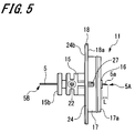
- FIG. 5 is a side view of the state in which the needle tube 5 is held by the first member 11.
- the needle tube 5 is passed through the through hole 21 (see FIG. 4) of the first member 11.
- the length (protrusion length L) by which the needle tip 5A of the needle tube 5 protrudes from the first member 11 is set in a range of 0.9 to 1.4 mm, and the portion of the needle tube 5 on the base end 5B side is set. Is set to be shorter than the length protruding from the first member 11.
- an adhesive is injected from the injection hole 22 opened on the side surface of the first member 11, and the needle tube 5 is fixed to the first member 11 (see FIG. 2). Thereby, the attaching operation of the needle tube 5 is completed, and the first member 11 holds the needle tube 5.
- a coating agent made of silicone resin, fluorine resin, or the like is applied to the needle tip 5A of the needle tube 5 and the needle protruding surface 16a and the outer surface 16b (see FIG. 3) of the adjusting unit 16.
- the coating layers 19 a and 19 b are formed on the adjustment unit 16.
- the coating agent infiltrates into the gap between the needle tube 5 and the first member 11 by capillary action.
- the adjusting portion 16 is provided with a discharge hole 23 (see FIG. 2) that communicates with the through hole 21 and opens to the outer surface.
- the coating agent that has passed through the needle tube 5 and infiltrated into the through hole 21 enters the discharge hole 23 from the inlet portion 23 b of the discharge hole 23, and is outside the adjustment portion 16 from the outlet portion 23 a of the discharge hole 23. It is discharged to the end surface 15 a of the base portion 15 and the flat surface 24 a of the connection piece 24. Thereby, it can prevent that a coating agent touches an adhesive agent and can prevent that the adhesive strength of the needle tube 5 and the 1st member 11 falls.
- the second member 12 with the elastic member 7 engaged in advance is connected to the first member 11 holding the needle tube 5. That is, the base portion 15 of the first member 11 and the proximal end 5B side portion of the needle tube 5 are inserted into the insertion portion 31 of the second member 12, and the connection piece 24 of the first member 11 is fixed to the fixing piece of the second member 12. 34 abut. At this time, the portion on the proximal end 5B side of the needle tube 5 is inserted into the insertion hole 45 of the elastic member 7 disposed in the second member 12, and is in close contact with the close contact portion 48 (see FIG. 2). Thereafter, the fixing piece 34 of the second member 12 is fixed to the connection piece 24 of the first member 11 by a fixing method such as adhesive, ultrasonic welding, laser welding, fixing screw, or the like. Thereby, the assembly of the injection needle assembly 2 is completed.
- a fixing method such as adhesive, ultrasonic welding, laser welding, fixing screw, or the like.
- the method for assembling the injection needle assembly 2 is not limited to the above-described method.
- the elastic member 7 is attached to the proximal end 5B side portion of the needle tube 5 held by the first member 11.
- the first member 11 and the second member 12 may be connected.
- the coating agent 19 is not applied to the needle tip 5A of the needle tube 5 and the needle protrusion surface 16a and the outer surface 16b of the adjustment unit 16 at the same time, but a first coating layer 19b is formed on the adjustment unit 16.
- the member 11 may be prepared in advance, and the coating agent may be applied only to the needle tip 5A of the needle tube 5.
- a user such as a doctor or a nurse performs priming in order to remove air from the syringe 3 filled with a medicine. That is, the user holds the syringe 3 so that the discharge part 52 faces vertically upward, and moves all the air in the liquid chamber 56 to the discharge part 52 side. Subsequently, the plunger (not shown) is pushed in the axial direction to move the gasket (not shown) to the discharge part 52 side. Thereby, the air in the liquid chamber 56 is discharged through the discharge portion 52. At this time, a part of the medicine in the liquid chamber 56 is also discharged. The discharged medicine forms droplets on the end surface 52 a of the discharge unit 52.
- the discharge part 52 of the syringe 3 is inserted into the insertion part 32 of the injection needle assembly 2. Then, the screw part 53 provided in the discharge part 52 is screwed into the screw groove 35 of the fitting part 32. Thereby, the mounting of the injection needle assembly 2 to the syringe 3 is completed, and the assembly of the medicine injection device 1 is completed. At this time, the liquid droplet may pass through the proximal end 5B of the needle tube 5, travel along the needle tip 5A, adhere to the needle protruding surface 16a, and remain due to surface tension.
- the medicine injection device 1 is operated so that the needle tip 5A faces vertically downward. As a result, the drug remaining on the needle projecting surface 16 a is shaken off from the drug injection device 1.
- the drug injection device 1 may perform priming to remove air after mounting the syringe 3 filled with the drug solution on the injection needle assembly 2, and in this case, the drug discharged from the needle tip 5A by priming may be performed. Adhesion to the needle protrusion surface 16a can be prevented.
- the end surface 17a of the stabilizing portion 17 is opposed to the skin.
- the needle tip 5A of the needle tube 5 faces the skin to be punctured.
- the drug injection device 1 is moved substantially perpendicularly to the skin, and the needle tip 5A is punctured into the skin and the end surface 17a of the stabilizing portion 17 is pressed against the skin.
- the coating layer 19b formed on the needle projecting surface 16a can come into contact with the skin to deform the skin flatly, and the needle tip 5A side of the needle tube 5 can be punctured into the skin by the projecting length L.
- the drug does not remain on the coating layer 19b formed on the needle projecting surface 16a by the above operation on the drug injection device 1, and the drug does not adhere to the skin.
- the end surface 17a of the stabilizing portion 17 is pressed until the contact surface 18a of the guide portion 18 contacts the skin.
- the length of the guide portion height Y (see FIG. 3) is set so that the needle tube 5 and the stabilizing portion 17 can puncture the skin with an appropriate pressing force. Therefore, the force that presses the skin by the stabilizing portion 17 becomes a predetermined value.
- the user can recognize an appropriate pressing force of the stabilizing portion 17, and the needle tip 5A and the blade surface 5a of the needle tube 5 can be reliably disposed on the upper skin portion.
- the guide part 18 becomes a mark which recognizes the appropriate pressing force of the stable part 17, the user can use the chemical injection apparatus 1 in comfort.
- the posture of the medicine injection device 1 is stabilized by the abutment of the stabilizing portion 17 on the skin, and the needle tube 5 can be punctured so as to be orthogonal to the surface of the skin.
- the blurring which arises in the needle tube 5 after puncture can be prevented, and the administration of the medicine can be performed stably.
- the needle tip 5A may not pierce the skin even if it is brought into contact with the skin.
- the skin inside the stable portion 17 is pulled and tension is applied to the skin. Therefore, it is difficult for the skin to escape from the needle tip 5 ⁇ / b> A of the needle tube 5. Therefore, by providing the stabilizing portion 17, it is possible to obtain an effect that the needle tip 5A is more easily pierced into the skin.
- the plunger (not shown) is pushed to move the gasket (not shown) to the discharge portion 52 side.
- the medicine filled in the liquid chamber 56 of the syringe 3 is pushed out from the discharge part 52, passes through the needle hole of the needle tube 5, and is injected into the upper skin part from the needle tip 5 ⁇ / b> A.
- the remaining amount of the medicine can be reduced.
- the configuration of the first member (particularly the adjustment unit) that can be used in the drug injection device of the present invention is not limited to the above-described embodiment, and various modifications can be considered.
- various modifications of the first member will be described with reference to FIGS.
- symbol is attached
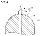
- FIG. 6 is a cross-sectional view showing the vicinity of the tip of the adjustment unit of the first modification.
- the adjustment portion 116 is formed by forming the needle protruding surface 16 a in the adjustment portion 16 (see FIG. 2) according to the above embodiment into a substantially hemispherical shape. That is, the adjusting portion 116 has a substantially hemispherical needle protrusion surface 116a.
- At least the needle projecting surface 116a is coated with a coating agent made of, for example, silicone resin or fluorine resin (lubricant treatment) to form a coating layer 117 (chemical removal mechanism).
- the coating layer 117 may be formed in the adjustment part 116 over the whole surface.
- the attached medicine when the medicine adheres to the coating layer 117, the attached medicine can be shaken off only by directing the needle tip 5A vertically downward, and the same effect as in the above embodiment can be obtained.
- the needle protrusion surface 116a is formed in a substantially hemispherical shape, when the needle tip 5A is directed vertically downward, the contact area of the drug with the coating layer 117 can be reduced.
- the attached medicine can be shaken off more easily than in the above embodiment. Therefore, it can prevent more reliably that a chemical
- the needle protruding surface 116a is formed in a substantially hemispherical shape in the adjusting portion 116 of this example, the shape of the needle protruding surface is not limited to this, and for example, the needle protruding surface may be formed in a tapered surface shape. The effect of can be obtained.
- Modification 2 In the said embodiment and the modification 1, it was set as the structure which can form a coating layer in the needle
- FIG. 7 is a cross-sectional view showing an adjustment portion of Modification 2-1.
- the adjusting unit 126 has a through hole 127 having a diameter larger than the diameter of the through hole 21 in the axial direction of the needle tube 5. It is formed.
- This through-hole 127 sucks in the medicine adhering to the needle projecting surface 126a that projects the portion of the needle tube 5 on the needle tip 5A side by capillary action.
- the inner wall portion 128 that defines the through-hole 127 functions as a medicine removing mechanism.
- the through-hole 127 needs to be formed so that the volume adhering to the needle protruding surface 126a is larger than the volume of the adhering liquid in order to suck the drug due to capillary action and hold the sucked drug.
- the diameter of the entire through hole 127 is increased in order to increase the volume of the through hole 127, there is a possibility that the capillary phenomenon does not occur. Therefore, as shown in FIG. 7, the volume of the through hole 127 can be secured by forming only the diameter of a part of the through hole 127 larger than the diameter of the other part.
- the adjustment unit 126 for example, when the medicine released from the needle tube 5 by priming always performed before puncture is transmitted to the needle tip 5a through the needle tip 5A, the attached medicine is caused by capillary action. Then, it is sucked into the through-hole 127 along the inner wall portion 128 and held in that state. As a result, the adhered drug can be prevented from remaining on the needle projecting surface 126a as it is, and the drug can be prevented from adhering to the skin during injection.
- the medicine removing mechanism may be configured to further include a water absorbing member 137 such as a nonwoven fabric or a water absorbing polymer on the surface of the inner wall portion 128 (Modification 2-2).
- a water absorbing member 137 such as a nonwoven fabric or a water absorbing polymer on the surface of the inner wall portion 128 (Modification 2-2).
- the medicine adhered to the needle protruding surface is sucked into the adjusting portion by a capillary phenomenon using a through hole into which the needle tube is inserted.
- a through-hole different from the through-hole into which the needle tube is inserted can be formed in the adjustment portion.
- the other through hole needs to open at least on the needle protruding surface.
- the shape of the needle protrusion surface of an adjustment part is made into the plane, it is not restricted to this.
- the shape of the needle protruding surface may be, for example, a substantially hemispherical shape as in Modification 1 or other surface shapes.
- a coating layer may be provided on the needle tip in the same manner as the needle tube of the embodiment or the first modification.
- the present invention is not limited to the embodiment described above and shown in the drawings, and various modifications can be made without departing from the scope of the invention described in the claims.
- the injection needle assembly may be configured without providing the elastic member.
- the second member and the elastic member may be integrally formed.
- SYMBOLS 1 Drug injection device, 2 ... Injection needle assembly, 3 ... Syringe, 5 ... Needle tube, 5A ... Needle tip, 5B ... Base end, 5a ... Blade surface, 6 ... Needle hub, 7 ... Elastic member, 11 ... First Member, 12 ... second member, 15 ... base portion, 16, 116, 126 ... adjusting portion, 16a, 116a, 126a ... needle protruding surface, 17 ... stabilizing portion, 18 ... guide portion, 19a, 19b, 117 ... coating layer 21, 127 ... through hole, 22 ... injection hole, 23 ... discharge hole, 23 a ... outlet part, 23 b ... inlet part, 24 ...
- connection piece 128 ... inner wall part, 137 ... water absorbing member, L ... projecting length, S ... Distance from the peripheral edge of the needle protruding surface to the peripheral surface of the needle tube, T: Distance from the inner wall surface of the stable portion to the outer peripheral surface of the adjusting portion, X: Guide portion length, Y: Guide portion height, d: Inner diameter
Landscapes
- Health & Medical Sciences (AREA)
- Vascular Medicine (AREA)
- Engineering & Computer Science (AREA)
- Anesthesiology (AREA)
- Biomedical Technology (AREA)
- Heart & Thoracic Surgery (AREA)
- Hematology (AREA)
- Life Sciences & Earth Sciences (AREA)
- Animal Behavior & Ethology (AREA)
- General Health & Medical Sciences (AREA)
- Public Health (AREA)
- Veterinary Medicine (AREA)
- Infusion, Injection, And Reservoir Apparatuses (AREA)
Abstract
生体に穿刺可能な針先を有する針管と、針管を保持する針ハブとを含んで構成される。針ハブは、針管の周囲に配置され、針先が突出する針突出面を有する調整部を備える。そして、調整部は、針突出面に付着した薬剤を除去する薬剤除去機構を有し、針管の針突出面から突出している部分の長さが3.0mm以下である。
Description
本発明は、針ハブから突出している針管の長さが3.0mm以下の注射針組立体及び薬剤注射装置に関する。
近年、鳥インフルエンザのヒトへの感染が報告されており、ヒトからヒトへの鳥インフルエンザの感染の大流行(パンデミック)による多くの被害が懸念されている。そこで、鳥インフルエンザに有効と考えられるプレパンデミックワクチン(インフルエンザワクチン)の備蓄が世界中で行われている。また、プレパンデミックワクチンを多くのヒトに投与するために、ワクチンの製造量を拡大させる検討が行われている。
ところで、インフルエンザワクチンは、一般的には、皮下投与もしくは筋肉内投与であるため、皮膚の下層部もしくはそれよりも深い部分に投与されている。また、免疫担当細胞が多く存在する皮膚上層部を標的部位として、インフルエンザワクチンを投与することにより、インフルエンザワクチンの投与量を少なしても、皮下投与や筋肉投与と同等の免疫獲得能が得られることが報告されている(非特許文献1)。したがって、インフルエンザワクチンを皮膚上層部に投与することによって、その投与量を減らすことができるので、インフルエンザワクチンをより多くのヒトに投与できる可能性がある。
ここで、皮膚は、表皮と、真皮と、皮下組織の一部との3部分から構成される。表皮は、皮膚表面から50~200μm程度の層であり、真皮は、表皮から続く1.5~3.5mm程度の層である。なお、皮膚上層部とは、皮膚のうちの表皮及び真皮を指す。
皮膚上層部への薬剤の投与方法としては、単針、多針、パッチ、ガス等を用いた方法が報告されている。そして、投与の安定性、信頼性、製造コストを考慮すると、皮膚上層部への投与方法としては、単針を用いた方法が最も適している。この単針を用いて皮膚上層部にワクチンを投与する方法として、古くからマントー法が知られている。マントー法は、一般的に26~27G(ゲージ)のサイズで、かつ、短ベベルの針先を有する針を皮膚に対して10~15°程度の斜め方向から2~5mm程度挿入して、100μL程度の薬剤を投与する方法である。
ところが、マントー法は、手技が難しく、高い技量が必要とされる。特に小児は投与時に動く可能性があるため、マントー法によってインフルエンザワクチンを投与することは難しい。したがって、簡便に皮膚上層部にワクチンを投与することのできるデバイスの開発が求められている。
そこで、突出させる針管の長さを規定する針突出面が形成されたリミッタを針ハブに接続して、皮膚上層部への薬剤の投与を行う注射針組立体が考えられた(特許文献1)。このリミッタは、針管の周囲を覆うように筒状に形成されており、針管との間に間隙を有するものである。このリミッタの皮膚に接触する針突出面から突出する針管の長さ(突出長)を0.5~3.0mmに規定し、皮膚から針を穿刺することにより、薬剤を皮膚上層部に投与するようになっている。
また、安定した穿刺を行うために、リミッタの周囲に、さらに針の穿刺する深さを調整することができる皮膚接触部を設けることも考えられる(特許文献2)。
このように、リミッタと皮膚接触部とを有する注射針組立体において、ワクチンなどの薬剤を収納したシリンジを針ハブに取りけた後にエア抜きを行うと、針先から薬液が漏洩し、リミッタと皮膚接触部との間に薬剤が付着するおそれがある。このため、シリンジを針ハブに取り付ける前にシリンジのエア抜きを行うことも考えられる。
R.T.Kenney et al. New England Journal of Medicine, 351, 2295-2301 (2004).
しかしながら、シリンジを針ハブに取り付ける前にシリンジのエア抜きを行っても、エア抜きを行ったシリンジを針ハブに取り付ける時に排出部に溜まっている薬剤が針を通じて、その針先から排出され、針排出面に付着し残留してしまうおそれがある。
本発明の目的は、上記の問題点を考慮し、針管が突出すると共に、薬剤投与の際に皮膚に接触する針突出面に薬剤が残留するのを防止できる注射針組立体及び薬剤注射装置を提供することにある。
上記課題を解決し、本発明の目的を達成するため、本発明の注射針組立体は、生体に穿刺可能な針先を有する針管と、針管を保持する針ハブとを含んで構成される。針ハブは、針管の周囲に配置され、針先が突出する針突出面を有する調整部を備える。そして、調整部は、針突出面に付着した薬剤を除去する薬剤除去機構を有し、針管の針突出面から突出している部分の長さが3.0mm以下である。なお、本発明の薬剤注射装置は、上記構成の注射針組立体に加えて、更に薬剤を収納するシリンジを備えたものである。
本発明の注射針組立体及び薬剤注射装置によれば、針突出面に付着した薬剤を除去する薬剤除去機構が調整部に設けられているので、例えばプライミングの際に薬剤が針突出面に付着しても、そのまま薬剤が針突出面に残留することを防止できる。その結果として、薬剤を投与する際に針突出面と皮膚とを接触させたとしても、薬剤の皮膚への付着を防ぐことができる。
以下、本発明の注射針組立体及び薬剤注射装置の実施形態例について、図1~図5を参照して説明する。なお、各図において共通の部材には、同一の符号を付す。また、本発明は、以下の形態に限定されるものではない。
なお、説明は以下の順序で行う。
1.注射針組立体及び薬剤注射装置の構成例
2.注射針組立体の組み立て
3.薬剤注射装置の使用方法
4.各種変形例
4-1.変形例1
4-2.変形例2
なお、説明は以下の順序で行う。
1.注射針組立体及び薬剤注射装置の構成例
2.注射針組立体の組み立て
3.薬剤注射装置の使用方法
4.各種変形例
4-1.変形例1
4-2.変形例2
1.注射針組立体及び薬剤注射装置の構成例
[薬剤注射装置]
まず、図1を参照して本発明の実施の形態例(以下、「本例」という。)にかかる注射針組立体及び薬剤注射装置について説明する。
図1は、本例の薬剤注射装置を示す分解図である。
[薬剤注射装置]
まず、図1を参照して本発明の実施の形態例(以下、「本例」という。)にかかる注射針組立体及び薬剤注射装置について説明する。
図1は、本例の薬剤注射装置を示す分解図である。
薬剤注射装置1は、針先を皮膚の表面に穿刺し、皮膚上層部に薬剤を注入するために用いる。この薬剤注射装置1は、注射針組立体2と、この注射針組立体2が着脱可能に接続されるシリンジ3とから構成される。
図1に示すように、注射針組立体2は、針孔を有する中空の針管5と、針管5が固定される針ハブ6と、針ハブ6内に配置される弾性部材7とを備える。また、針ハブ6は、針管5を保持する第1部材11(保持部)と、シリンジ3が接続される第2部材12(コネクタ部)とで構成される。
次に、薬剤注射装置1の上述した各構成部品について、図2から図4を参照して説明する。
図2は、薬剤注射装置1の断面図である。図3は、第1部材11を構成する調整部を示す断面図であり、図4は、薬剤注射装置1を分解して示す断面図である。
図2は、薬剤注射装置1の断面図である。図3は、第1部材11を構成する調整部を示す断面図であり、図4は、薬剤注射装置1を分解して示す断面図である。
[注射針組立体]
注射針組立体2の針管5は、ISOの医療用針管の基準(ISO9626:1991/Amd.1:2001(E))で22~33ゲージのサイズ(外径0.2~0.7mm)のものが使用できる。なお、注射針組立体2を皮膚上層部への投与に用いる場合には、26~33ゲージの針管5を使用することができ、好ましくは30~33ゲージのものが使用できる。
注射針組立体2の針管5は、ISOの医療用針管の基準(ISO9626:1991/Amd.1:2001(E))で22~33ゲージのサイズ(外径0.2~0.7mm)のものが使用できる。なお、注射針組立体2を皮膚上層部への投与に用いる場合には、26~33ゲージの針管5を使用することができ、好ましくは30~33ゲージのものが使用できる。
針管5の軸方向の一端には、刃面5aを有する針先5Aが設けられる。この針先5Aとは反対側に位置する針管5の軸方向の他端が基端5B(図4参照)に相当する。針管5の軸方向における刃面5aの長さ(以下、「ベベル長B」という)は、後述する皮膚上層部の最薄の厚さである1.4mm(成人)以下であればよく、また、33ゲージの針管に短ベベルを形成したときのベベル長Bである約0.5mm以上であればよい。つまり、ベベル長Bは、0.5~1.4mmの範囲に設定されるのが好ましい。更に、ベベル長Bは、皮膚上層部の最薄の厚さが0.9mm(小児)以下、すなわち、ベベル長Bが0.5~0.9mmの範囲であればなおよい。なお、短ベベルとは、一般的な注射用針で用いられる刃面、すなわち針の長手方向に対して18~25°をなす刃面を指す。
また、針管5の針先5Aの表面には、例えばシリコーン樹脂やフッ素系樹脂等からなるコーティング剤が塗布され(潤滑剤処理)、コーティング層19a(図2参照)が形成される。これにより、針管5を生体に穿刺した際に、皮膚と針管5との摩擦を低減することができ、穿刺時に伴う痛みを軽減させることが可能となる。その上、潤滑剤処理が施された針先5Aの表面における撥水性を向上させることもでき、穿刺前に必ず行われるプライミング(シリンジ3内の空気を抜く作業)によって針管5から放出された薬剤が針先5Aに付着した際に、そのまま薬剤が針先5Aに残留することを防止できる。
針管5の材料としては、例えば、ステンレス鋼を挙げることができるが、これに限定されるものではなく、アルミニウム、アルミニウム合金、チタン、チタン合金、その他の金属等を用いることができる。また、針管5は、ストレート針だけでなく、少なくとも一部がテーパー構造となっているテーパー針を適用することができる。テーパー針としては、針先端部に比べて基端部が大きい径を有しており、その中間部分をテーパー構造とすればよい。また、針管5の軸方向に直交する面の断面形状は、円形だけでなく、三角形等の多角形であってもよい。そして、この針管5は、針ハブ6に固定される。
[針ハブ]
次に、針ハブ6について説明する。針ハブ6の第1部材11及び第2部材12は、別部材として形成されるが、一体に形成することもできる。これら第1部材11及び第2部材12の材質としては、ポリカーボネート、ポリプロピレン、ポリエチレン等の合成樹脂を挙げることができる。
次に、針ハブ6について説明する。針ハブ6の第1部材11及び第2部材12は、別部材として形成されるが、一体に形成することもできる。これら第1部材11及び第2部材12の材質としては、ポリカーボネート、ポリプロピレン、ポリエチレン等の合成樹脂を挙げることができる。
第1部材11は、略円柱状のベース部15と、調整部16と、安定部17と、ガイド部18とを備えている。ベース部15は、その軸方向に垂直な端面15a,15bを有する。調整部16は、ベース部15の軸方向の一方の端面15aの中央部に設けられており、ベース部15の軸方向に突出する。また、この調整部16の軸は、ベース部15の軸と一致する。
ベース部15及び調整部16の軸上には、針管5が貫通する貫通孔21(図4参照)が設けられる。そして、ベース部15には、貫通孔21に接着剤を注入するための注入孔22(図2及び図4参照)が設けられる。この注入孔22は、ベース部15の外周面に開口しており、貫通孔21と略直交するように貫通孔21に連通する。すなわち、注射針組立体2の組立時には、注入孔22から貫通孔21へ注入される接着剤によって、針管5がベース部15に固着される。
調整部16の端面は、針管5の針先5A側の部分が突出する針突出面16aである。針突出面16aは、針管5の軸方向に直交する平面として形成される。そして、調整部16における針突出面16a及びこの針突出面16aに連続する外面16bには、図3に示すように、例えばシリコーン樹脂やフッ素系樹脂等からなるコーティング剤が塗布され(潤滑剤処理)、コーティング層19b(薬剤除去機構)が形成される。これにより、潤滑剤処理が施された針突出面16a及び外面16bにおける撥水性を向上させることができる。その結果、例えば穿刺前に必ず行われるプライミングにより針管5から放出された薬剤が針先5Aを伝わってコーティング層19bに付着した際に、針先5Aを鉛直下方に向けるだけで当該付着した薬剤を薬剤注射装置1から振り落とすことができる。したがって、この付着した薬剤がそのままコーティング層19bに残留することを防止でき、注射時における薬剤の皮膚への付着を未然に防ぐことができる、という効果がある。
なお、本例では、調整部16の針突出面16a及び外面16bにコーティング層19bを形成したが、より薬剤が付着しやすい針突出面16aにだけコーティング層19bを形成してもよい。また、針突出面16a及び外面16bにおける一部の面にコーティング層19bを形成してもよい。このように調整部16にコーティング層19bを形成した場合でも、上記した効果と同様の効果を得ることができる。
この調整部16には、針管5を伝わって貫通孔21に浸潤するコーティング剤を排出するための排出孔23が設けられる。排出孔23は、調整部16の外面16bから貫通孔21に連通するように形成される。また、排出孔23は、その軸が貫通孔21の軸と略直交するように設けられる。そして、排出孔23は、調整部16の外壁に出口部23aと、貫通孔21に連通する入口部23bとを有する。
これにより、針管5の針先5A、並びに、調整部16の針突出面16a及び外面16bにシリコーン樹脂やフッ素系樹脂等からなるコーティング剤を塗布する際に、コーティング剤が調整部16に設けた貫通孔21を伝わってベース部15側に浸潤することを防ぐことができる。その結果、針管5とベース部15とを固着する接着剤にコーティング剤が触れることを防止でき、針管5とベース部15との接着強度が低下することを防ぐことが可能である。
なお、本例では、排出孔23を、調整部16の一方の外面から貫通孔21を間に挟んで対向する位置の他方の外面まで貫通する孔で形成し、かつ、貫通孔21の軸方向と直交する方向に貫通させた例を説明したが、これに限定されるものではない。排出孔23は、調整部16の外面から貫通孔21まで貫通する孔であってもその目的を達成できるものである。
更に、排出孔23を調整部16に形成した例を説明したが、排出孔23は、接着剤を注入する注入孔22よりも針管5の針先5A側に形成されていればよく、排出孔23を第1部材11のベース部15に形成してもよい。また、排出孔23を、第1部材11の複数箇所に形成してもよい。
針管5の基端5B側の部分は、ベース部15の軸方向の他方の端面15bから突出する。ベース部15は、端面15b側から第2部材12内に挿入され、針管5の基端5B側の部分が弾性部材7の後述する挿通孔45に挿通される。そして、ベース部15の端面15bが弾性部材7の後述する端面41aに当接される。
また、ベース部15の外周面には、接続片24が設けられる。この接続片24は、ベース部15の半径方向の外側に向けて突出するリング状のフランジとして形成され、ベース部15の軸方向に対向する平面24a,24bを有する。接続片24の平面24bには、第2部材12が接続される。また、接続片24の先端部には、ガイド部18が設けられる。ガイド部18については、後で詳しく説明する。
ところで、調整部16の針突出面16aに形成されたコーティング層19bは、針管5を皮膚上層部に穿刺するときに、皮膚の表面に接触して針管5を穿刺する深さを規定する。つまり、針管5が皮膚上層部に穿刺される深さは、針突出面16aのコーティング層19bから突出する針管5の長さ(以下、「突出長L」という。)によって決定される。
皮膚上層部の厚みは、皮膚の表面から真皮層までの深さに相当し、概ね、0.5~3.0mmの範囲内にある。そのため、針管5の突出長Lは、0.5~3.0mmの範囲に設定することができる。
ここで、ワクチンは一般的に上腕部に投与されるが、皮膚上層部への投与を考えた場合は皮膚が厚い肩周辺部、特に三角筋の部分がふさわしいと考えられる。そこで、小児19人と大人31人について、三角筋の皮膚上層部の厚みを測定した。この測定は、超音波測定装置(NP60R-UBM 小動物用高解像度用エコー、ネッパジーン(株))を用いて、超音波反射率の高い皮膚上層部を造影することで行った。なお、測定値が対数正規分布となっていたため、幾何平均によってMEAN±2SDの範囲を求めた。
その結果、小児の三角筋における皮膚上層部の厚みは、0.9~1.6mmであった。また、成人の三角筋における皮膚上層部の厚みは、遠位部で1.4~2.6mm、中央部で1.4~2.5mm、近位部で1.5~2.5mmであった。以上のことから、三角筋における皮膚上層部の厚みは、小児の場合で0.9mm以上、成人の場合で1.4mm以上であることが確認された。したがって、三角筋の皮膚上層部における注射において、針管5の突出長Lは、0.9~1.4mmの範囲に設定することが好ましい。
突出長Lをこのように設定することで、針先5Aの刃面5aを皮膚上層部に確実に配置させることが可能となる。その結果、刃面5aに開口する針孔(薬剤排出口)は、刃面5a内のいかなる位置にあっても、皮膚上層部に配置させることが可能である。なお、薬剤排出口が皮膚上層部に位置しても、針先5Aが皮膚上層部に深く刺されば、針先5A端部の側面と切開された皮膚との間から薬剤が皮下に流れてしまうため、刃面5aが確実に皮膚上層部に位置することが重要である。
なお、薬剤注射装置1を皮膚上層部への薬剤の投与に用いる場合には、26ゲージよりも太い針管では、ベベル長Bを1.0mm以下にすることは難しい。したがって、針管5の突出長Lを好ましい範囲(0.9~1.4mm)に設定するには、26ゲージ以下の太さの針管5を使用することが好ましい。
針突出面16aは、その周縁から針管5の周面までの距離Sが1.4mm以下となるように形成し、好ましくは0.3~1.4mmの範囲で形成する。この針突出面16aの周縁から針管5の周面までの距離Sは、皮膚上層部へ薬剤を投与することで形成される水疱に圧力が加わることを考慮して設定される。つまり、針突出面16aは、皮膚上層部に形成される水疱よりも十分に小さく、水疱の形成を妨げない大きさに設定される。その結果、針突出面16aが針管5の周囲の皮膚を押圧して、投与された薬剤が皮膚から漏れるということを防止することができる。
安定部17は、ベース部15に設けた接続片24の平面24aから突出する筒状に形成される。安定部17の筒孔には、針管5及び調整部16が配置される。つまり、安定部17は、針管5が貫通する調整部16の周囲を覆うように形成され、針管5の針先5Aから半径方向に離間して設けられる。
安定部17には、キャップ(不図示)が着脱可能に嵌合される。このキャップ(不図示)は、針管5の針先5Aを覆う。これにより、針ハブ6をシリンジ3に装着する場合に、針先5Aが使用者の指先等に触れないようにすることができる。また、使用済みの薬剤注射装置1或いは注射針組立体2を常に安全な状態に保つことができ、使用者は、安心して使用済みの薬剤注射装置1或いは注射針組立体2の廃棄処理等を行うことができる。
図2に示すように、安定部17の端面17aは、調整部16の針突出面16aよりも針管5の基端5B側に位置する。針管5の針先5Aを生体に穿刺すると、まず、針突出面16aが皮膚の表面に接触し、その後、安定部17の端面17aが皮膚に接触する。このとき、安定部17の端面17aが皮膚に接触することで薬剤注射装置1の姿勢が安定し、針管5の穿刺姿勢を皮膚に対して略垂直な姿勢に保つことができる。
なお、安定部17の端面17aは、針突出面16aと同一平面上に位置させたり、また、針突出面16aよりも針管5の針先5A側に位置させたりしても、針管5の穿刺姿勢を皮膚に対して略垂直な姿勢に保つことができる。なお、安定部17を皮膚に押し付けた際の皮膚の盛り上がりを考慮すると、安定部17の端面17aと針突出面16aとの間の軸方向における距離は、1.3mm以下に設定することが好ましい。
また、安定部17の内径dは、皮膚に形成される水疱の直径と同等であるか、それよりも大きい値に設定される。具体的には、安定部17の内壁面から針突出面16aの周縁までの距離Tが4mm~15mmの範囲となるように設定される。これにより、安定部17の内壁面から水疱に圧力が印加されことによって水疱形成が阻害されることを防止することができる。
安定部17の内壁面から調整部16の外周面までの最短距離Tは、4mm以上であれば、特に上限はない。しかしながら、距離Tを大きくすると、安定部17の外径が大きくなるため、小児のように細い腕に針管5を穿刺する場合に、安定部17の端面17a全体を皮膚に接触させることが難しくなる。そのため、距離Tは、小児の腕の細さを考慮して15mmを最大と規定することが好ましい。
また、針突出面16aの周縁から針管5の周面までの距離Sが約0.3mm以上であれば、調整部16が皮膚に進入することはない。したがって、安定部17の内壁面から針突出面16aの周縁までの距離T(4mm以上)及び針突出面16aの直径(約0.3mm)を考慮すると、安定部17の内径dは約9mm以上に設定することができる。
なお、安定部17は、円筒状部材に限定されるものではなく、例えば、中心に筒孔を有し、外形及び/又は開口が資格や六角等の多角形の筒状部材であってもよい。
ガイド部18は、接続片24における安定部17よりも第1部材11における半径方向の外側に位置する先端側の部分である。このガイド部18は、皮膚と接触する接触面18aを有する。接触面18aは、接続片24における平面24aの一部であり、安定部17の端面17aと略平行をなす平面である。ガイド部18の接触面18aが皮膚に接触するまで安定部17を皮膚に押し付けることにより、安定部17及び針管5が皮膚を押圧する力を常に所定値以上に確保することができる。これにより、針管5の針突出面16aから突出している部分(突出長Lに相当)が確実に皮膚内に穿刺される。
ガイド部18の接触面18aから安定部17の端面17aまでの距離(以下、「ガイド部高さ」という。)Yは、針管5及び安定部17が適正な押圧力で皮膚を押圧して穿刺することができるような長さである。なお、針管5及び安定部17の適正な押圧力は、例えば、3~20Nである。その結果、使用者に対して針管5及び安定部17による皮膚への適正な押圧力をガイド部18が案内し、針管5の針先5A(刃面5a)を皮膚上層部に確実に配置させることができる。それゆえ、本例では、使用者に安心感を与えることができる。
ガイド部高さYは、安定部17の内径dと、ガイド部18の先端面から安定部17の外周面までの長さ(以下、「ガイド部長さ」という。)Xに基づいて適宜決定される。例えば、安定部17の内径dが12mmであり、ガイド部長さXが3.0mmのとき、ガイド部高さYは、2.3~6.6mmの範囲に設定される。
次に、第2部材12について説明する。第2部材12は、略筒状に形成される。この第2部材12の軸方向の一端部は、第1部材11のベース部15を挿入する挿入部31であり、他端部は、シリンジ3の後述する排出部52を嵌入する嵌入部32である。挿入部31の筒孔31aは、第1部材11のベース部15に対応した大きさに設定される。
挿入部31には、第1部材11の接続片24に接続される固定片34が設けられる。この固定片34は、挿入部31の端部に連続して半径外方向に突出するリング状のフランジとして形成される。注射針組立体2の組立時には、固定片34に、第1部材11に設けた接続片24の平面24bが当接し、固着される。固定片34と接続片24との固着方法としては、例えば、接着剤、超音波溶着、レーザ溶着、固定ねじ等の手法を挙げることができる。
嵌入部32の筒孔32aは、シリンジ3の排出部52に対応した大きさに設定されており、挿入部31側に向かって連続的にその径が小さくなる。嵌入部32の内面には、シリンジ3の排出部52を螺合させるためのねじ溝35が形成される。
挿入部31と嵌入部32との間には、弾性部材7が係合する係合部37が設けられる。この係合部37は、第2部材12の内面から半径内方向に突出する凸部として形成され、第2部材12の軸方向に略直交する係合面37a,37bを有する。係合部37の係合面37aには、弾性部材7の後述するフランジ部42が係合され、係合面37bには、弾性部材7のストッパ突部43が係合される。
[弾性部材]
次に、弾性部材7について説明する。弾性部材7は、針ハブ6の第2部材12内に配置され、第1部材11とシリンジ3との間に介在される。この弾性部材7は、略円柱状の本体部41と、この本体部41の軸方向の一端に設けられたフランジ部42と、本体部41の軸方の他端に設けられたストッパ突部43とを有する。
次に、弾性部材7について説明する。弾性部材7は、針ハブ6の第2部材12内に配置され、第1部材11とシリンジ3との間に介在される。この弾性部材7は、略円柱状の本体部41と、この本体部41の軸方向の一端に設けられたフランジ部42と、本体部41の軸方の他端に設けられたストッパ突部43とを有する。
本体部41は、軸方向に垂直な端面41a,41bを有する。本体部41の端面41aには、第1部材11のベース部15の端面15bが当接し、端面41bには、シリンジ3に設けられた排出部52の先端が液密に当接する。つまり、端面41bは、排出部52の先端が液密に当接する当接面である。
本体部41には、ベース部15の端面15bから突出した針管5の基端5B側の部分が挿通される挿通孔45が設けられる。この挿通孔45は、本体部41の軸方向に延びており、端面41a,41bに開口する。本体部41の内面は、端面側離間部46と、当接面側離間部47と、密着部48とから形成される。
端面側離間部46は、端面41aにおける挿通孔45の開口を形成する。この端面側離間部46は、針管5の外周面から離間しており、端面41aに向かうにつれて挿通孔45の径が連続的に大きくなるようなテーパー状に形成される。これにより、ベース部15の端面15bから突出した針管5の基端5B側の部分を挿通孔45に容易に挿通することができる。なお、挿通孔45における端面側離間部46の形状は、針管5が挿通孔45に挿通し易い形状であれば、テーパー状に限定されるものではない。
当接面側離間部47は、端面41bにおける挿通孔45の開口を形成する。この当接面側離間部47は、針管5の外周面から離間しており、端面41bに向かうにつれて挿通孔45の径が連続的に大きくなるようなテーパー状に形成されている。弾性部材7に当接面側離間部47を設けることにより、本体部41の端面41b側の部分が弾性変形しても、針管5の基端5Bを覆い、針孔を塞ぐことを防止することができる。
また、挿通孔45における当接面側離間部47は、テーパー状に形成したものに限定されるものではなく、例えば密着部48の径よりも大きく針管5の外周面から離間するような凹部であってもよい。すなわち、挿通孔45における当接面側離間部47の形状は、本体部41の端面41b側が弾性変形して針管5の基端5Bを覆い、針孔を塞ぐことが防止できる形状であればよい。
密着部48は、端面側離間部46と当接面側離間部47との間に形成される。この密着部48は、針管5の外周面に液密に密着する。これにより、シリンジ3内の薬剤は、針管5と弾性部材7との間から針ハブ6の第1部材11側へ浸透しないようにすることができる。
フランジ部42は、本体部41の外周面から半径外方向に突出するリング状に形成される。このフランジ部42の外径は、第1部材11のベース部15の端面15bの外径と略等しい。そのため、フランジ部42の一方の平面は、第2部材12に設けた係合部37の係合面37aと当接し、他方の平面は、第1部材11のベース部15の端面15bと当接する。弾性部材7は、第2部材12の係合部37と第1部材11のベース部15によってフランジ部42が挟持されて針ハブ6に取り付けられる。
ストッパ突部43は、フランジ部42と同様に、本体部41の外周面から半径外方向に突出するリング状に形成される。このストッパ突部43は、第2部材12に設けた係合部37の係合面37bに係合する。弾性部材7は、フランジ部42及びストッパ突部43が第2部材12の係合部37に係合することにより、軸方向への移動が係止される。
弾性部材7の材質としては、天然ゴム、合成ゴム、シリコーンゴムのような各種ゴム材料や、ポリウレタン系、スチレン系等の各種熱可塑性エストラマー、或いはそれらの混合物等の弾性材料が挙げられる。
[シリンジ]
シリンジ3は、シリンジ本体51と、このシリンジ本体51に連続する排出部52とを備える。シリンジ本体51は、円形の筒体からなる。排出部52は、シリンジ本体51の軸方向の一端から突出し、シリンジ本体51よりも小さい外径の円形の筒体からなる。この排出部52は、その先端に向かうにつれて径が連続的に小さくなるようにテーパー状に形成される。排出部52の先端となる端面52aは、軸方向に直交する平面であり、弾性部材7の端面41bに液密に当接する。また、排出部52の外周面には、針ハブ6の第2部材12に螺合させるためのねじ部53が設けられる。
シリンジ3は、シリンジ本体51と、このシリンジ本体51に連続する排出部52とを備える。シリンジ本体51は、円形の筒体からなる。排出部52は、シリンジ本体51の軸方向の一端から突出し、シリンジ本体51よりも小さい外径の円形の筒体からなる。この排出部52は、その先端に向かうにつれて径が連続的に小さくなるようにテーパー状に形成される。排出部52の先端となる端面52aは、軸方向に直交する平面であり、弾性部材7の端面41bに液密に当接する。また、排出部52の外周面には、針ハブ6の第2部材12に螺合させるためのねじ部53が設けられる。
シリンジ本体51内には、ガスケット(不図示)が収納されている。シリンジ本体51の内部は、ガスケットにより2つの空間に仕切られており、排出部52に連通する一方の空間が、排出部52内の空間と共に液室56を形成する。シリンジ本体51内の他方の空間には、プランジャ(不図示)が配置される。プランジャは、ガスケットに接続されており、シリンジ本体51の他端の開口から突出する。このプランジャを操作することにより、ガスケットがシリンジ本体51内で軸方向に移動され、液室56への薬剤の吸引及び液室56に充填された薬剤の排出が行われる。
なお、シリンジ本体51内には、予め薬剤が充填されていてもよい。
なお、シリンジ本体51内には、予め薬剤が充填されていてもよい。
シリンジ本体51及び排出部52の材質としては、ポリカーボネート、ポリプロピレン、ポリエチレン等の合成樹脂を用いてもよく、また、ステンレス、アルミニウム等の金属を用いてもよい。
2.注射針組立体の組み立て
次に、上述したような構成を有する注射針組立体の組み立て方法について図2~5を参照して説明する。
図5は、第1部材11に針管5を保持された状態の側面図である。
次に、上述したような構成を有する注射針組立体の組み立て方法について図2~5を参照して説明する。
図5は、第1部材11に針管5を保持された状態の側面図である。
まず、図5に示すように、針管5を第1部材11の貫通孔21(図4参照)に貫通させる。このとき、針管5の針先5Aが第1部材11から突出する長さ(突出長L)は、0.9~1.4mmの範囲に設定されており、針管5の基端5B側の部分が第1部材11から突出する長さに比べて短くなるように設定される。次に、第1部材11の側面に開口する注入孔22から接着剤を注入し、針管5を第1部材11に固着する(図2参照)。これにより、針管5の取り付け作業が完了し、第1部材11が針管5を保持した状態になる。
次に、針管5の針先5A、並びに、調整部16の針突出面16a及び外面16b(図3参照)にシリコーン樹脂やフッ素系樹脂等からなるコーティング剤を塗布する。これにより、コーティング層19a,19bが調整部16に形成される。このとき、毛細管現象によって、コーティング剤が、針管5と第1部材11との隙間に浸潤する。しかしながら、調整部16には、貫通孔21に連通し、且つ外面まで開口した排出孔23(図2参照)が設けられている。その結果、針管5を伝わって貫通孔21内に浸潤したコーティング剤は、排出孔23の入口部23bから排出孔23内に侵入し、排出孔23の出口部23aから調整部16の外側であるベース部15の端面15a及び接続片24の平面24aへ排出される。これにより、コーティング剤が接着剤に触れることを防止でき、針管5と第1部材11との接着強度が低下することを防ぐことができる。
次に、針管5を保持した第1部材11に、予め弾性部材7が係合された第2部材12を接続する。すなわち、第1部材11のベース部15及び針管5の基端5B側の部分を、第2部材12の挿入部31に挿入し、第1部材11の接続片24を第2部材12の固定片34に当接させる。このとき、針管5の基端5B側の部分は、第2部材12内に配置された弾性部材7の挿通孔45に挿通され、密着部48と液密に密着する(図2参照)。その後、第2部材12の固定片34を第1部材11の接続片24に、接着剤、超音波溶着、レーザ溶着、固定ねじ等の固着方法によって固着する。これにより、注射針組立体2の組み立てが完了する。
なお、注射針組立体2の組み立て方法は、上述した方法に限定されるものではなく、例えば、弾性部材7を第1部材11に保持された針管5の基端5B側の部分に取り付けてから、第1部材11と第2部材12とを接続させるようにしてもよい。また、上述したように針管5の針先5A、並びに、調整部16の針突出面16a及び外面16bに同時にコーティング剤を塗布するのではなく、調整部16にコーティング層19bが形成された第1部材11を予め用意しておき、針管5の針先5Aにだけコーティング剤を塗布するようにしてもよい。
3.薬剤注射装置の使用方法
次に、薬剤注射装置1の使用方法について説明する。
まず、使用者(医師や看護師等)は、薬剤が充填されたシリンジ3内の空気を抜くためにプライミングを行う。すなわち、使用者は、排出部52が鉛直上方を向くようにシリンジ3を持ち、液室56内の空気をすべて排出部52側に移動させる。続いて、プランジャ(不図示)を軸方向に押して、ガスケット(不図示)を排出部52側に移動させる。これにより、液室56内の空気が、排出部52を通って排出される。このとき、液室56内の薬剤の一部も排出される。この排出された薬剤が排出部52の端面52aに液滴を形成する。
次に、薬剤注射装置1の使用方法について説明する。
まず、使用者(医師や看護師等)は、薬剤が充填されたシリンジ3内の空気を抜くためにプライミングを行う。すなわち、使用者は、排出部52が鉛直上方を向くようにシリンジ3を持ち、液室56内の空気をすべて排出部52側に移動させる。続いて、プランジャ(不図示)を軸方向に押して、ガスケット(不図示)を排出部52側に移動させる。これにより、液室56内の空気が、排出部52を通って排出される。このとき、液室56内の薬剤の一部も排出される。この排出された薬剤が排出部52の端面52aに液滴を形成する。
この状態で注射針組立体2の嵌入部32にシリンジ3の排出部52を挿入する。そして、排出部52に設けたねじ部53を嵌入部32のねじ溝35に螺合させる。これにより、シリンジ3に対する注射針組立体2の装着が完了し、薬剤注射装置1の組み立てが完了する。この時、液滴が針管5の基端5Bを通って、針先5Aを伝って針突出面16aに付着し、表面張力により残留することがある。
しかしながら、針突出面16aは、撥水性の高い材料(シリコーン樹脂やフッ素系樹脂等)で形成されているコーティング層19bを有するので、針先5Aが鉛直下方を向くように薬剤注射装置1を操作することにより、針突出面16aに残留している薬剤が薬剤注射装置1から振り落とされる。
なお、薬剤注射装置1は、薬液が充填されたシリンジ3を注射針組立体2に装着した後、空気を抜くプライミングを行っても良く、この場合、プライミングにより針先5Aから排出された薬剤の針突出面16aへの付着を防ぐことができる。
以上の操作が完了した後、針管5の針先5Aを生体に穿刺するには、まず、安定部17の端面17aを皮膚に対向させる。これにより、針管5の針先5Aが、穿刺する皮膚に対向する。次に、薬剤注射装置1を皮膚に対して略垂直に移動させ、針先5Aを皮膚に穿刺すると共に安定部17の端面17aを皮膚に押し付ける。すると、針突出面16aに形成されたコーティング層19bが皮膚に接触して皮膚を平らに変形させることができ、針管5の針先5A側を突出長Lだけ皮膚に穿刺することができる。このとき、薬剤注射装置1に対する上記操作により、薬剤は針突出面16aに形成されたコーティング層19bに残留しておらず、薬剤が皮膚に付着することはない。
次に、ガイド部18の接触面18aが皮膚に接触するまで安定部17の端面17aを押し付ける。ここで、ガイド部高さY(図3参照)は、針管5及び安定部17が適正な押圧力で皮膚に穿刺することができるようにその長さが設定されている。そのため、安定部17によって皮膚を押圧する力が所定の値になる。
その結果、安定部17の適正な押圧力を使用者に認識させることができ、針管5の針先5A及び刃面5aを確実に皮膚上層部に配置させることができる。このように、ガイド部18が安定部17の適正な押圧力を認識させる目印となるので、使用者が安心して薬剤注射装置1を使用することができる。
また、安定部17が皮膚に当接することで、薬剤注射装置1の姿勢が安定し、針管5を皮膚の表面に対して直交するように穿刺することができる。また、穿刺後に針管5に生じるブレを防止することができ、薬剤の安定した投与を行うことができる。また、例えば0.5mm程度のごく短い突出長Lの針管5では、針先5Aを皮膚に当接させても皮膚に刺さらない場合がある。しかし、安定部17に押し付けられた皮膚が垂直方向に押し下げられることにより、安定部17の内側の皮膚が引っ張られて皮膚に張力が加わった状態となる。そのため、針管5の針先5Aに対して皮膚が逃げ難くなる。したがって、安定部17を設けることにより、皮膚に針先5Aがより刺さり易くなるという効果を得ることもできる。
針管5の針先5A側の部分を皮膚に穿刺した後、プランジャ(不図示)を押してガスケット(不図示)を排出部52側に移動させる。これにより、シリンジ3の液室56に充填された薬剤は、排出部52から押し出され、針管5の針孔を通って針先5Aから皮膚上層部に注入される。このとき、排出部52の先端と針管5の基端5Bとの間に空間が形成されていないため、薬剤の残存量を少なくすることができる。
4.各種変形例
本発明の薬剤注射装置で用いることのできる第1部材(特に調整部)の構成は、上記実施形態に限定されず、様々な変形例が考えられる。以下では、第1部材の各種変形例について図6~8を参照して説明する。なお、上記実施形態の薬剤注射装置1と共通の構成については、同じ符号を付し、その説明を省略する。
本発明の薬剤注射装置で用いることのできる第1部材(特に調整部)の構成は、上記実施形態に限定されず、様々な変形例が考えられる。以下では、第1部材の各種変形例について図6~8を参照して説明する。なお、上記実施形態の薬剤注射装置1と共通の構成については、同じ符号を付し、その説明を省略する。
4-1.変形例1
図6は、変形例1の調整部の先端付近を示す断面図である。
調整部116は、図6に示すように、上記実施形態に係る調整部16(図2参照)における針突出面16aを略半球状に形成したものである。すなわち、調整部116は、その針突出面116aが略半球面状となっている。そして、少なくともこの針突出面116aには、例えばシリコーン樹脂やフッ素系樹脂等からなるコーティング剤が塗布され(潤滑剤処理)、コーティング層117(薬剤除去機構)が形成されている。なお、調整部116には、その表面全体に亘ってコーティング層117が形成されていてもよい。
図6は、変形例1の調整部の先端付近を示す断面図である。
調整部116は、図6に示すように、上記実施形態に係る調整部16(図2参照)における針突出面16aを略半球状に形成したものである。すなわち、調整部116は、その針突出面116aが略半球面状となっている。そして、少なくともこの針突出面116aには、例えばシリコーン樹脂やフッ素系樹脂等からなるコーティング剤が塗布され(潤滑剤処理)、コーティング層117(薬剤除去機構)が形成されている。なお、調整部116には、その表面全体に亘ってコーティング層117が形成されていてもよい。
この例においても、薬剤がコーティング層117に付着した際に、針先5Aを鉛直下方に向けるだけで、当該付着した薬剤を振り落とすことができ、上記実施形態と同様の効果が得られる。
更に、この例の調整部116では、針突出面116aを略半球面状に形成したので、針先5Aを鉛直下方に向けた際に、薬剤のコーティング層117に対する接触面積を減らすことができ、上記実施形態よりも当該付着した薬剤を容易に振り落とすことができる。したがって、薬剤がそのままコーティング層117に残留することをより確実に防止でき、注射の際に薬剤が皮膚に付着することを未然に防ぐことができる。なお、この例の調整部116は針突出面116aが略半球状に形成されているが、針突出面の形状はこれに限らず、例えば針突出面がテーパー面状に形成されていても同様の効果を得ることができる。
4-2.変形例2
上記実施形態及び変形例1では、調整部の少なくとも針突出面にコーティング層を形成して当該針突出面に付着した薬剤を容易に振り落とすことができる構成としたが、本発明はこれに限定されない。例えば、調整部の針突出面に付着した薬剤を吸い込んで調整部内部に留めるような構成としてもよい。
上記実施形態及び変形例1では、調整部の少なくとも針突出面にコーティング層を形成して当該針突出面に付着した薬剤を容易に振り落とすことができる構成としたが、本発明はこれに限定されない。例えば、調整部の針突出面に付着した薬剤を吸い込んで調整部内部に留めるような構成としてもよい。
図7は、変形例2-1の調整部を示す断面図である。
調整部126には、上記実施形態の調整部16(図4参照)に形成された貫通孔21の代わりに、この貫通孔21の径よりも径が大きい貫通孔127が針管5の軸方向に形成される。この貫通孔127は、毛細管現象によって、針管5の針先5A側の部分を突出させる針突出面126aに付着した薬剤を吸い込む。この例では、当該貫通孔127を画成する内壁部128が薬剤除去機構として作用する。
調整部126には、上記実施形態の調整部16(図4参照)に形成された貫通孔21の代わりに、この貫通孔21の径よりも径が大きい貫通孔127が針管5の軸方向に形成される。この貫通孔127は、毛細管現象によって、針管5の針先5A側の部分を突出させる針突出面126aに付着した薬剤を吸い込む。この例では、当該貫通孔127を画成する内壁部128が薬剤除去機構として作用する。
貫通孔127は、針突出面126aに付着した薬剤を毛細管現象によって吸い込むと共に吸い込んだ薬剤を保持するために、その体積が当該付着した液体の体積よりも大きくなるように形成される必要がある。しかし、貫通孔127の体積を大きくすべく、貫通孔127全体の径を大きくすると、毛細管現象が発生しないおそれがある。それゆえ、図7に示すように、貫通孔127の一部分の径だけをその他の部分の径よりも大きく形成することにより、貫通孔127の体積を確保することができる。
このように調整部126の構成により、例えば穿刺前に必ず行われるプライミングにより針管5から放出された薬剤が針先5Aを伝わって針突出面126aに付着した際に、付着した薬剤が毛細管現象により、当該内壁部128を伝って貫通孔127に吸い込まれ、その状態で保持される。その結果、付着した薬剤がそのまま針突出面126aに残留することを防止でき、注射の際に薬剤が皮膚に付着するのを未然に防ぐことができる。
なお、図8に示すように、薬剤除去機構として、内壁部128の表面上に不織布や吸水性ポリマーなどの吸水部材137を更に備えるような構成とすることもできる(変形例2-2)。この構成によれば、毛細管現象によって貫通孔127に吸い込まれた薬剤を吸水部材137で吸収・保持することができる。これにより、薬剤注射装置を操作している最中に、薬剤が貫通孔127から外へ飛び出ることをより確実に防止できる。
図7及び図8に示したように、変形例2では、針管が挿入される貫通孔を利用した毛細管現象により、針突出面に付着した薬剤を調整部内に吸い込む構成とした。しかしながら、当該針管を挿入する貫通孔とは別の貫通孔を調整部に形成することもできる。ただし、この場合、当該別の貫通孔は、少なくとも針突出面に開口している必要がある。
また、図7及び図8に示したように、変形例2では、調整部の針突出面の形状を平面としているが、これに限られない。針突出面の形状は、例えば、変形例1のような略半球面状やその他の面形状であってもよい。
また、この変形例2の針管において、上記実施形態或いは変形例1の針管と同様に、その針先にコーティング層を設けてもよい。
なお、本発明は上述しかつ図面に示した実施の形態に限定されるものではなく、特許請求の範囲に記載した発明の要旨を逸脱しない範囲内で種々の変形実施が可能である。例えば、上述した実施の形態例では、第1部材と第2部材との間に弾性部材を設けた例を説明したが、弾性部材を設けずに注射針組立体を構成してもよく、また、第2部材と弾性部材を一体に形成してもよい。
1…薬剤注射装置、 2…注射針組立体、 3…シリンジ、 5…針管、 5A…針先、 5B…基端、 5a…刃面、 6…針ハブ、 7…弾性部材、 11…第1部材、 12…第2部材、 15…ベース部、 16,116,126…調整部、 16a,116a,126a…針突出面、 17…安定部、 18…ガイド部、 19a,19b,117…コーティング層、 21,127…貫通孔、 22…注入孔、 23…排出孔、 23a…出口部、 23b…入口部、 24…接続片、 128…内壁部、 137…吸水部材、 L…突出長、 S…針突出面の周縁から針管の周面までの距離、 T…安定部の内壁面から調整部の外周面までの距離、 X…ガイド部長さ、 Y…ガイド部高さ、 d…内径
Claims (9)
- 生体に穿刺可能な針先を有する針管と、
前記針管を保持する針ハブと、を含み、
前記針ハブは、
前記針管の周囲に配置され、前記針先が突出する針突出面を有する調整部を備え、
前記調整部は、
前記針突出面に付着した薬剤を除去する薬剤除去機構を有し、
前記針管の前記針突出面から突出している部分の長さが3.0mm以下である
ことを特徴とする注射針組立体。 - 前記薬剤除去機構は、前記調整部に形成された撥水性を有するコーティング層である
ことを特徴とする請求項1に記載の注射針組立体。 - 前記コーティング層は、少なくとも前記針突出面に形成されている
ことを特徴とする請求項2に記載の注射針組立体。 - 前記調整部には、前記針突出面に開口する貫通孔が形成されており、
前記薬剤除去機構は、前記貫通孔を画成する内壁部により構成され、前記針突出面に付着した薬剤を吸い込む
ことを特徴とする請求項1に記載の注射針組立体。 - 前記薬剤除去機構は、更に、前記内壁部上に形成され、吸い込んだ薬剤を吸収する吸水部材を有する
ことを特徴とする請求項4に記載の注射針組立体。 - 前記針突出面が略半球面状である
ことを特徴とする請求項1に記載の注射針組立体。 - 前記針管は、前記針先側の先端部の表面がコーティング剤によって覆われている
ことを特徴とする請求項1に記載の注射針組立体。 - 前記針管の太さは、26~33ゲージである
ことを特徴とする請求項1に記載の注射針組立体。 - 薬剤を収納するシリンジと、
生体に穿刺可能な針先を有する針管と、
前記針管を保持する針ハブと、を含み、
前記針ハブは、
前記針管の周囲に配置され、前記針先が突出する針突出面を有する調整部を備え、
前記調整部は、
前記針突出面に付着した薬剤を除去する薬剤除去機構を有し、
前記針管の前記針突出面から突出している部分の長さが3.0mm以下である
ことを特徴とする薬剤注射装置。
Applications Claiming Priority (2)
| Application Number | Priority Date | Filing Date | Title |
|---|---|---|---|
| JP2011105116 | 2011-05-10 | ||
| JP2011-105116 | 2011-05-10 |
Publications (1)
| Publication Number | Publication Date |
|---|---|
| WO2012153563A1 true WO2012153563A1 (ja) | 2012-11-15 |
Family
ID=47139049
Family Applications (1)
| Application Number | Title | Priority Date | Filing Date |
|---|---|---|---|
| PCT/JP2012/055095 WO2012153563A1 (ja) | 2011-05-10 | 2012-02-29 | 注射針組立体及び薬剤注射装置 |
Country Status (1)
| Country | Link |
|---|---|
| WO (1) | WO2012153563A1 (ja) |
Cited By (4)
| Publication number | Priority date | Publication date | Assignee | Title |
|---|---|---|---|---|
| WO2015107774A1 (ja) * | 2014-01-16 | 2015-07-23 | テルモ株式会社 | 皮膚上層部への薬液注入用注射器 |
| WO2016104584A1 (ja) * | 2014-12-25 | 2016-06-30 | 第一三共株式会社 | 皮内投与インフルエンザワクチン組成物 |
| EP3248634A4 (en) * | 2015-01-20 | 2018-10-03 | Terumo Kabushiki Kaisha | Injection needle assembly and injector provided therewith for injecting drug solution into upper layer of skin |
| EP3275487A4 (en) * | 2015-03-27 | 2018-12-26 | Terumo Kabushiki Kaisha | Injection needle assembly and drug injection device |
Citations (4)
| Publication number | Priority date | Publication date | Assignee | Title |
|---|---|---|---|---|
| WO2007063828A1 (ja) * | 2005-11-29 | 2007-06-07 | Ttm Co., Ltd. | 体液採取装置およびその方法 |
| JP2008532701A (ja) * | 2005-03-14 | 2008-08-21 | ベクトン・ディキンソン・アンド・カンパニー | 短針を有する注射器のための充填システムおよび方法 |
| JP4383168B2 (ja) * | 2001-09-12 | 2009-12-16 | ベクトン・ディキンソン・アンド・カンパニー | マイクロ針投与デバイスおよび薬物投与デバイス |
| WO2011040221A1 (ja) * | 2009-09-30 | 2011-04-07 | テルモ株式会社 | 注射針組立体および薬剤注射装置 |
-
2012
- 2012-02-29 WO PCT/JP2012/055095 patent/WO2012153563A1/ja active Application Filing
Patent Citations (4)
| Publication number | Priority date | Publication date | Assignee | Title |
|---|---|---|---|---|
| JP4383168B2 (ja) * | 2001-09-12 | 2009-12-16 | ベクトン・ディキンソン・アンド・カンパニー | マイクロ針投与デバイスおよび薬物投与デバイス |
| JP2008532701A (ja) * | 2005-03-14 | 2008-08-21 | ベクトン・ディキンソン・アンド・カンパニー | 短針を有する注射器のための充填システムおよび方法 |
| WO2007063828A1 (ja) * | 2005-11-29 | 2007-06-07 | Ttm Co., Ltd. | 体液採取装置およびその方法 |
| WO2011040221A1 (ja) * | 2009-09-30 | 2011-04-07 | テルモ株式会社 | 注射針組立体および薬剤注射装置 |
Cited By (8)
| Publication number | Priority date | Publication date | Assignee | Title |
|---|---|---|---|---|
| WO2015107774A1 (ja) * | 2014-01-16 | 2015-07-23 | テルモ株式会社 | 皮膚上層部への薬液注入用注射器 |
| JPWO2015107774A1 (ja) * | 2014-01-16 | 2017-03-23 | テルモ株式会社 | 皮膚上層部への薬液注入用注射器 |
| EP3095476A4 (en) * | 2014-01-16 | 2017-09-27 | Terumo Kabushiki Kaisha | Syringe for injecting drug solution into upper skin layer |
| US10413681B2 (en) | 2014-01-16 | 2019-09-17 | Terumo Kabushiki Kaisha | Syringe for injecting drug solution into upper layer of skin |
| WO2016104584A1 (ja) * | 2014-12-25 | 2016-06-30 | 第一三共株式会社 | 皮内投与インフルエンザワクチン組成物 |
| EP3248634A4 (en) * | 2015-01-20 | 2018-10-03 | Terumo Kabushiki Kaisha | Injection needle assembly and injector provided therewith for injecting drug solution into upper layer of skin |
| US10413680B2 (en) | 2015-01-20 | 2019-09-17 | Terumo Kabushiki Kaisha | Injection needle assembly and injector provided therewith for injecting drug solution into upper layer of skin |
| EP3275487A4 (en) * | 2015-03-27 | 2018-12-26 | Terumo Kabushiki Kaisha | Injection needle assembly and drug injection device |
Similar Documents
| Publication | Publication Date | Title |
|---|---|---|
| JP6284595B2 (ja) | 注射針組立体及び薬剤注射装置 | |
| JP5726741B2 (ja) | 注射針組立体および薬剤注射装置 | |
| JP5894582B2 (ja) | 注射針組立体及び薬剤注射装置 | |
| JP5604438B2 (ja) | 注射針組立体および薬剤注射装置 | |
| JP5719522B2 (ja) | 薬剤投与器具及び薬剤注射装置 | |
| JP5667571B2 (ja) | 注射針組立体及び薬剤注射装置 | |
| WO2011122224A1 (ja) | 注射針組立体および薬剤注射装置 | |
| WO2010116832A1 (ja) | 注射針組立体および薬剤注射装置 | |
| JP5756793B2 (ja) | 注射針組立体及び薬剤注射装置 | |
| JP5955838B2 (ja) | 注射針組立体及び薬剤注射装置 | |
| WO2012153563A1 (ja) | 注射針組立体及び薬剤注射装置 | |
| WO2011040222A1 (ja) | 注射針組立体及び薬剤注射装置 | |
| WO2016158140A1 (ja) | 注射針組立体および薬剤注射装置 | |
| JP5432272B2 (ja) | 注射補助具及び薬剤注射装置 | |
| WO2012160852A1 (ja) | 注射針組立体及び薬剤注射装置 | |
| WO2012157313A1 (ja) | 注射針ユニット | |
| WO2012157318A1 (ja) | 注射針組立体及び薬剤注射装置 | |
| WO2012157312A1 (ja) | 注射針ユニット | |
| JP5270424B2 (ja) | 薬剤注射装置および注射針組立体 | |
| WO2012132761A1 (ja) | 注射針ユニット、収納ケース、注射針組立体及び薬剤注射装置 | |
| WO2012160855A1 (ja) | 注射針組立体及び薬剤注射装置 | |
| WO2012157323A1 (ja) | 注射針組立体及び薬剤注射装置 | |
| JP2016187431A (ja) | 注射針組立体および薬剤注射装置 |
Legal Events
| Date | Code | Title | Description |
|---|---|---|---|
| 121 | Ep: the epo has been informed by wipo that ep was designated in this application |
Ref document number: 12781823 Country of ref document: EP Kind code of ref document: A1 |
|
| NENP | Non-entry into the national phase |
Ref country code: DE |
|
| 122 | Ep: pct application non-entry in european phase |
Ref document number: 12781823 Country of ref document: EP Kind code of ref document: A1 |
|
| NENP | Non-entry into the national phase |
Ref country code: JP |