WO2012153506A1 - 投写用広角レンズおよびこれを用いた投写型表示装置 - Google Patents
投写用広角レンズおよびこれを用いた投写型表示装置 Download PDFInfo
- Publication number
- WO2012153506A1 WO2012153506A1 PCT/JP2012/002984 JP2012002984W WO2012153506A1 WO 2012153506 A1 WO2012153506 A1 WO 2012153506A1 JP 2012002984 W JP2012002984 W JP 2012002984W WO 2012153506 A1 WO2012153506 A1 WO 2012153506A1
- Authority
- WO
- WIPO (PCT)
- Prior art keywords
- lens
- lens group
- projection
- wide
- angle
- Prior art date
- Legal status (The legal status is an assumption and is not a legal conclusion. Google has not performed a legal analysis and makes no representation as to the accuracy of the status listed.)
- Ceased
Links
Images








Classifications
-
- G—PHYSICS
- G02—OPTICS
- G02B—OPTICAL ELEMENTS, SYSTEMS OR APPARATUS
- G02B13/00—Optical objectives specially designed for the purposes specified below
- G02B13/04—Reversed telephoto objectives
-
- G—PHYSICS
- G02—OPTICS
- G02B—OPTICAL ELEMENTS, SYSTEMS OR APPARATUS
- G02B13/00—Optical objectives specially designed for the purposes specified below
- G02B13/16—Optical objectives specially designed for the purposes specified below for use in conjunction with image converters or intensifiers, or for use with projectors, e.g. objectives for projection TV
-
- G—PHYSICS
- G02—OPTICS
- G02B—OPTICAL ELEMENTS, SYSTEMS OR APPARATUS
- G02B13/00—Optical objectives specially designed for the purposes specified below
- G02B13/18—Optical objectives specially designed for the purposes specified below with lenses having one or more non-spherical faces, e.g. for reducing geometrical aberration
-
- G—PHYSICS
- G02—OPTICS
- G02B—OPTICAL ELEMENTS, SYSTEMS OR APPARATUS
- G02B13/00—Optical objectives specially designed for the purposes specified below
- G02B13/22—Telecentric objectives or lens systems
Definitions
- the present invention relates to a wide-angle lens for projection and a projection display device, and in particular, a projection suitable for use in a projector device equipped with a light valve such as a liquid crystal display element or a DMD (Digital Micromirror Device: registered trademark).
- the present invention relates to a wide-angle lens for use and a projection display device using the same.
- projection projector devices using light valves such as liquid crystal display elements and DMDs have been widely used.
- the projection lens used in such a projection display device has a small F number, a long back focus so that a color synthesizing prism or the like can be disposed, a reduction side is almost telecentric, and a light valve resolution. It is required to have high optical performance commensurate with Examples of conventionally known projection lenses include those described in Patent Documents 1 to 3 below.
- the present invention has been made in view of the above circumstances, has a wide angle of view with a total angle of view of 130 degrees or more, a small F number, a long back focus, miniaturization and cost reduction, It is an object of the present invention to provide a projection wide-angle lens in which various aberrations are well corrected and a projection display device using the same.
- the wide-angle lens for projection according to the present invention includes, in order from the magnification side, a first lens group including two aspheric lenses, a second lens group composed of three negative meniscus lenses having a convex surface facing the magnification side, and at least A third lens group including a pair of cemented lenses and having negative refractive power, and a fourth lens group including at least two cemented lenses and one aspheric lens and having positive refractive power,
- the third lens group and the fourth lens group have the longest distance among adjacent lens groups in the system, and satisfy the following conditional expressions (1) to (3) It is.
- f123 Composite focal length from the first lens group to the third lens group f: Focal length of the entire system f4: Focal length of the fourth lens group Bf: Back focus on the reduction side (air conversion distance)
- the wide angle lens for projection it is preferable that at least one of the following conditional expressions (4) to (6) or any combination thereof is satisfied.
- f2 focal length of the second lens group
- f3 focal length of the third lens group
- d 3-4 distance on the optical axis between the third lens group and the fourth lens group when the projection distance is infinite
- the fourth lens group includes three or more positive lenses made of a material having an Abbe number of 80 or more in the d-line.
- the focus adjustment when the projection distance is changed is performed by moving only the second lens group and the third lens group in the optical axis direction, and the projection distance is reduced from a distance. It is preferable that the second lens group is moved to the reduction side and the third lens group is moved to the enlargement side during the focus adjustment when the direction is changed.
- a projection display device of the present invention includes a light source, a light valve, an illumination optical unit that guides a light beam from the light source to the light valve, and the projection wide-angle lens described above, and transmits the light beam from the light source to the light valve. And is projected onto a screen by the projection wide-angle lens described above.
- the “enlargement side” means the projection side (screen side), and the screen side is also referred to as the enlargement side for convenience in the case of reduced projection.
- the “reduction side” means the original image display area side (light valve side), and the light valve side is also referred to as the reduction side for the sake of convenience in the case of reduced projection.
- the surface shape of the lens and the sign of refractive power in the projection wide-angle lens of the present invention are considered in the paraxial region when an aspheric surface is included.
- the “lens group” does not necessarily include a plurality of lenses but also includes a single lens.
- the configuration of each lens group is suitably set and is configured to satisfy the conditional expressions (1) to (3).
- the projection type display device can be provided.
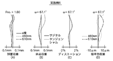
- FIGS. 8A to 8D are diagrams showing aberrations of the wide-angle lens for projection according to the first embodiment of the present invention.
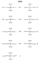
- FIGS. 9A to 9I are lateral aberration diagrams of the wide-angle lens for projection according to Example 1 of the present invention.
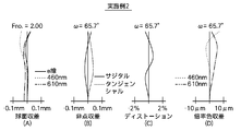
- FIGS. 10A to 10D are diagrams showing aberrations of the wide-angle lens for projection according to the second embodiment of the present invention.
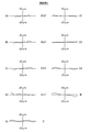
- FIGS. 11A to 11I are lateral aberration diagrams of the wide-angle lens for projection according to the second embodiment of the present invention.
- FIGS. 12A to 12D are diagrams showing aberrations of the wide-angle lens for projection according to the third embodiment of the present invention.
- FIGS. 13A to 13I are lateral aberration diagrams of the wide-angle lens for projection according to the third embodiment of the present invention.
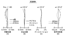
- FIGS. 14A to 14D are aberration diagrams of the wide-angle lens for projection according to the fourth embodiment of the present invention.
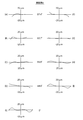
- FIGS. 15A to 15I are lateral aberration diagrams of the wide-angle lens for projection according to the fourth embodiment of the present invention.
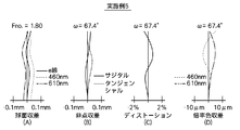
- FIGS. 16A to 16D are aberration diagrams of the wide-angle lens for projection according to the fifth embodiment of the present invention.
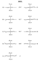
- 17A to 17I are lateral aberration diagrams of the wide-angle lens for projection according to the fifth embodiment of the present invention.
- FIGS. 18A to 18D are graphs showing aberrations of the wide-angle lens for projection according to the sixth embodiment of the present invention.
- FIGS. 19A to 19I are lateral aberration diagrams of the wide-angle lens for projection according to the sixth embodiment of the present invention.
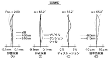
- 20A to 20D are graphs showing aberrations of the wide-angle lens for projection according to the seventh embodiment of the present invention.
- 21A to 21I are lateral aberration diagrams of the wide-angle lens for projection according to the seventh embodiment of the present invention.
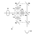
- 1 is a schematic configuration diagram of a projection display device according to an embodiment of the present
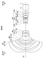
- FIGS. 1 to 7 are cross-sectional views showing a configuration example of a projection wide-angle lens according to an embodiment of the present invention, and correspond to projection wide-angle lenses of Examples 1 to 7 described later, respectively. Since the basic configuration of the example shown in FIGS. 1 to 7 is the same and the method of illustration is also the same, here, the wide-angle lens for projection according to the embodiment of the present invention will be described mainly with reference to FIG. To do.
- the wide-angle lens for projection according to the present embodiment shown in FIG. 1 is arranged in order from the enlargement side (the side indicated by arrow -Z in the figure) to the reduction side (the side indicated by arrow + Z in the figure) along the optical axis Z1.
- the four lens groups of one lens group G1, second lens group G2, third lens group G3, and fourth lens group G4 are arranged.
- a glass block (including a filter unit) 2 mainly including a color synthesis prism and an image display surface 1 of a light valve such as a liquid crystal display element or a DMD are arranged on the reduction side of the projection wide-angle lens. An example is shown.
- the first lens group G1 is configured to include two aspheric lenses.
- the first lens group G1 on the most enlarged side includes at least two aspheric lenses, which is advantageous for realizing a wide angle and a small F number.
- the aspherical lens only needs to have at least one aspherical surface, but both surfaces are aspherical, which is advantageous for good aberration correction.
- the first lens group G1 preferably has a negative refractive power for widening the angle.
- the first lens group G1 shown in FIG. 1 includes two negative meniscus lenses L1 and L2 in the paraxial region.
- the first lens group G1 has two lenses having a negative meniscus shape in the paraxial region, one of the paraxial regions faces the object side in the paraxial region, and the other faces the image side in the paraxial region. It is preferable to have a shape with a convex surface.
- the first lens group G1 preferably has a two-lens configuration as described above when importance is placed on downsizing and cost reduction. However, the first lens group G1 has three lenses having a protective function arranged further on the enlargement side. It is good also as a structure.
- the second lens group G2 is a lens group having a negative refractive power as a whole. As shown in FIG. 1, the second lens group G2 is configured to include three negative meniscus lenses L3, L4, and L5 having a convex surface facing the enlargement side. Thereby, the negative refracting power of the second lens group G2 can be dispersed in the three negative meniscus single lenses, and light rays can be gently bent to suppress the occurrence of coma aberration and field curvature. it can.
- the third lens group G3 is a lens group having a negative refractive power as a whole.
- the third lens group G3 is configured to include at least one cemented lens in which a positive lens and a negative lens are cemented.
- the cemented lens in the third lens group G3 it is possible to satisfactorily correct axial chromatic aberration and lateral chromatic aberration.
- the third lens group G3 includes two cemented lenses, it is further advantageous for correcting axial chromatic aberration and lateral chromatic aberration.
- the third lens group G3 shown in FIG. 1 includes a cemented lens obtained by cementing a lens L6 that is a biconcave lens and a lens L7 that is a biconvex lens, a lens L8 that is a biconcave lens, and a lens L9 that is a positive lens in order from the magnification side.
- This is a four-lens configuration in which a cemented lens in which the lenses are cemented is arranged.
- the third lens group G3 may have a five-lens configuration including a biconcave lens, a biconvex lens, a positive meniscus lens, and a cemented lens obtained by cementing the biconcave lens and the biconvex lens. Since the third lens group G3 includes at least two positive lenses and at least two negative lenses, it is possible to satisfactorily correct axial chromatic aberration and lateral chromatic aberration.
- the fourth lens group G4 is a lens group having a positive refractive power as a whole.
- the fourth lens group G4 is configured to include at least two cemented lenses and one aspheric lens.
- the cemented lens included in the fourth lens group G4 is obtained by cementing at least one positive lens and at least one negative lens.
- the fourth lens group G4 preferably has three or more cemented surfaces in which a positive lens and a negative lens are cemented. In such a configuration, the fourth lens group G4 is further advantageous in correcting axial chromatic aberration and lateral chromatic aberration.
- various aberrations can be favorably corrected.
- the fourth lens group includes three or more positive lenses made of a material having an Abbe number of 80 or more in the d-line.
- the fourth lens group G4 which is a positive lens group, includes at least two cemented lenses and one aspherical lens, and further includes three or more positive lenses having an Abbe number of 80 or more. It is possible to simultaneously optimize the size of the entire system and correct various aberrations including axial chromatic aberration and lateral chromatic aberration.
- the fourth lens group G4 includes, for example, a lens L10 that is a biconvex lens, a lens L11 that is a biconcave lens, and a lens L12 that is a positive lens in order from the magnification side, as in the example illustrated in FIG.
- the interval on the optical axis of the third lens group G3 and the fourth lens group G4 is configured to be the longest among the intervals on the optical axis of adjacent lens groups in the entire system. This makes it easy to dispose a diaphragm, a beam splitting / combining member, and the like between the third lens group G3 and the fourth lens group G4.
- the wide-angle lens for projection according to the present embodiment is configured to satisfy the following conditional expressions (1) to (3). ⁇ 3.8 ⁇ f123 / f ⁇ 1.6 (1) 6.6 ⁇ f4 / f ⁇ 11.5 (2) 5.1 ⁇ Bf / f ⁇ 6.4 (3)
- f123 Combined focal length from the first lens group G1 to the third lens group G3
- f4 Focal length of the entire system
- f4 Bf Back focus on the reduction side (air equivalent distance)
- the combined refractive power from the first lens group G1 to the third lens group G3 is negative. If the lower limit of conditional expression (1) is not reached, the combined focal length from the first lens group G1 to the third lens group G3 becomes long, and the combined refractive power from the first lens group G1 to the third lens group G3 becomes weak. Therefore, it is difficult to ensure the back focus. If the upper limit of conditional expression (1) is exceeded, the combined focal length from the first lens group G1 to the third lens group G3 will be shortened, and the amount of coma, field curvature, and astigmatism will increase, and aberration will be reduced. It becomes difficult to correct well.
- conditional expression (3) If the lower limit of conditional expression (3) is not reached, the back focus is shortened, making it difficult to arrange a color synthesis prism or the like. If the upper limit of conditional expression (3) is exceeded after sufficiently ensuring the back focus, the focal length of the entire system becomes short, making it difficult to correct various aberrations.
- the wide-angle lens for projection according to the present embodiment has a configuration described below as appropriate.
- it may have one of the structures described below, or may have any combination.
- f2 Focal length of the second lens group G2
- f123 Composite focal length from the first lens group G1 to the third lens group G3
- conditional expression (4) If the lower limit of conditional expression (4) is not reached, the amount of coma and field curvature will increase. If the upper limit of conditional expression (4) is exceeded, the diameter of the most magnified lens in the first lens group G1 will increase.
- f3 focal length of the third lens group G3
- f123 composite focal length from the first lens group G1 to the third lens group G3
- conditional expression (5) If the lower limit of conditional expression (5) is not reached, the first lens group G1 and the second lens group G2 will be enlarged, and the cost will be increased by increasing the diameter. If the upper limit of conditional expression (5) is exceeded, it will be difficult to ensure the back focus.
- Conditional expression (6) is an expression relating to the longest lens group interval in the entire system. If the lower limit of conditional expression (6) is not reached, it will be difficult to satisfactorily correct various aberrations and secure back focus. If the upper limit of conditional expression (6) is exceeded, the lens system will be enlarged.
- conditional expressions (1-1) to (6-1) are satisfied instead of the conditional expressions (1) to (6).
- -3.2 ⁇ f123 / f ⁇ -1.8 (1-1) 7.2 ⁇ f4 / f ⁇ 9.4 (2-1) 5.2 ⁇ Bf / f ⁇ 5.9 (3-1) 2.2 ⁇ f2 / f123 ⁇ 3.2 (4-1) 5.4 ⁇ f3 / 123 ⁇ 9.6 (5-1) 4.4 ⁇ d 3-4 /f ⁇ 9.8 (6-1)
- the wide-angle lens for projection according to the present embodiment is configured such that focus adjustment is performed by moving the second lens group G2 and the third lens group G3 in the optical axis direction, and the projection distance is reduced from a long distance.
- the focus adjustment when the distance is changed is preferably performed by moving the second lens group G2 to the reduction side and the third lens group G3 to the enlargement side.
- the focus mechanism is compared with a method in which the entire lens system is moved to perform focus adjustment, or a method in which the focus adjustment is performed by moving the lens group including the first lens group G1 formed of a lens having a large diameter. Can be simplified, and the cost can be reduced.
- a liquid crystal display element is used as a light valve, or a light beam separation optical system or a light beam synthesis optical system is provided on the reduction side of the projection wide-angle lens. Since a PBS (Polarized Beam Beam Splitter) prism or a color synthesis prism may be disposed as the projection wide-angle lens of this embodiment, it is preferable that the reduction side is telecentric.
- a PBS Polarized Beam Beam Splitter
- a color synthesis prism may be disposed as the projection wide-angle lens of this embodiment, it is preferable that the reduction side is telecentric.
- the projection wide-angle lens of the present embodiment has a wide angle of view of 130 degrees or more, F number is small as F1.8 to F2.0, the reduction side is almost telecentric, and has a long back focus.
- F number is small as F1.8 to F2.0
- the reduction side is almost telecentric, and has a long back focus.
- FIG. 22 is a schematic configuration diagram of a projection display apparatus according to an embodiment of the present invention.
- the projection display device shown in FIG. 22 includes a light source 20, transmissive liquid crystal display panels 11a to 11c as light valves corresponding to each color light, and an illumination optical unit 30 that guides a light beam from the light source 20 to the light valve. ing.
- the illumination optical unit 30 includes dichroic mirrors 12 and 13 for color separation, a cross dichroic prism 14 for color synthesis, condenser lenses 16a to 16c, and total reflection mirrors 18a to 18c. In FIG. 22, the configuration between the light source 20 and the dichroic mirror 12 is not shown.
- White light from the light source 20 is separated into three colored light beams (G light, B light, and R light) by the dichroic mirrors 12 and 13 in the illumination optical unit 30, and then the optical path is respectively transmitted by the total reflection mirrors 18a to 18c.
- the light After being deflected and incident on the transmissive liquid crystal display panels 11a to 11c corresponding to the light beams of the respective colors through the condenser lenses 16a to 16c, the light is modulated and color-combined by the cross dichroic prism 14, and then applied to the projection wide-angle lens 10. Incident light is projected onto a screen (not shown) by the projection wide-angle lens 10.
- the wide-angle lens 10 for projection is schematically shown.
- Example 1 The configuration of the wide-angle lens for projection of Example 1 is as shown in FIG.
- the wide-angle lens for projection in Example 1 includes, in order from the magnification side, a first lens group G1 having a negative refractive power, a second lens group G2 having a negative refractive power, and a third lens group G3 having a negative refractive power.
- the fourth lens group G4 having a positive refractive power is arranged.
- the reduction side of the projection wide-angle lens is substantially telecentric.
- a glass block (including a filter unit) 2 mainly including a color synthesis prism and an image display surface 1 of a light valve are disposed.
- the first lens group G1 includes, in order from the magnification side, a negative meniscus lens L1 having a convex surface facing the reduction side in the paraxial region and a negative meniscus lens L2 having a convex surface facing the magnification side in the paraxial region. It is arranged and configured. Both the lens L1 and the lens L2 have aspheric surfaces on both sides.
- the second lens group G2 includes three negative meniscus lenses L3 to L5 having a convex surface facing the enlargement side.
- the third lens group G3 includes, in order from the magnification side, a cemented lens obtained by cementing a biconcave lens L6 and a biconvex lens L7, a biconcave lens L8, and a positive meniscus shape having a convex surface facing the magnification side.
- a cemented lens in which the lens L9 is cemented is arranged.
- the fourth lens group G4 includes, in order from the enlargement side, a biconvex lens L10, a biconcave lens L11, a cemented lens in which a positive meniscus lens L12 having a convex surface facing the enlargement side, and a biconvex shape.
- a cemented lens obtained by cementing a biconcave lens L17 and a biconvex lens L18 and a biconvex lens L19 are arranged.
- the lens L14 has two aspheric surfaces.
- This projection wide-angle lens is configured to perform focus adjustment by moving the second lens group G2 and the third lens group G3 in the optical axis direction, and when the projection distance changes from a long distance to a short distance.
- the focus adjustment is performed by moving the second lens group G2 to the reduction side and the third lens group G3 to the enlargement side.
- Table 1 shows basic lens data of the wide-angle lens for projection in Example 1.
- Table 1 includes the glass block.
- the Ri column indicates the radius of curvature of the i-th surface
- the Di column indicates the surface spacing on the optical axis Z1 between the i-th surface and the i + 1-th surface.
- the d-line wavelength 587.6 nm
- the ⁇ dj column indicates the Abbe number of the j-th component with respect to the d-line.
- the sign of the radius of curvature is positive when the surface shape is convex on the enlargement side and negative when the surface shape is convex on the reduction side.
- the value in the lowermost column of the Di column is the distance from the reduction side surface of the glass block to the image display surface 1.
- the distance between the first lens group G1 and the second lens group G2, the distance between the second lens group G2 and the third lens group G3, and the distance between the third lens group G3 and the fourth lens group G4 vary according to the projection distance.
- the values when the projection distance is infinite are entered in parentheses in the columns D4, D10, and D16 corresponding to these intervals.
- the lower part of Table 1 shows values of D4, D10, and D16 when the projection distance is 1250 mm, 630 mm, and 460 mm.
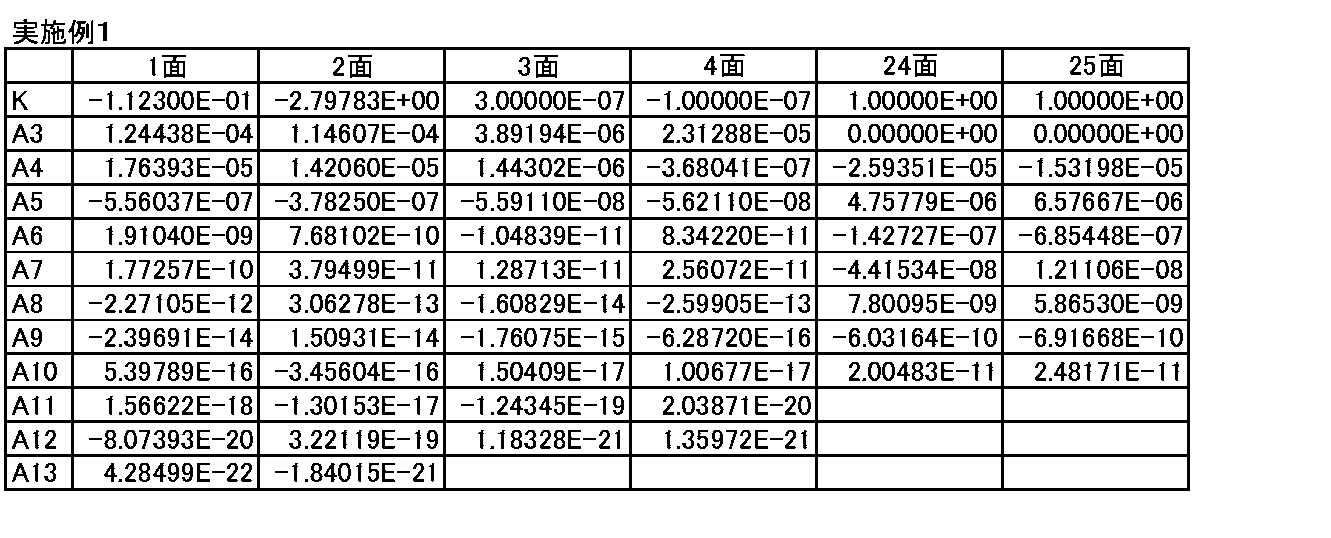
- Table 2 shows the aspheric coefficients of the aspheric surfaces of the projection wide-angle lens of Example 1.
- the numerical value “E ⁇ n” (n: integer) of the aspheric coefficient in Table 2 means “ ⁇ 10 ⁇ n ”, and “E + n” means “ ⁇ 10 n ”.
- Zd Length of perpendicular line drawn from the point on the aspherical surface at a distance Y from the optical axis to the tangential plane (plane perpendicular to the optical axis) of the aspherical surface
- Y Distance from the optical axis
- C Curvature K near the optical axis
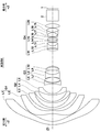
- Example 2 The configuration of the wide-angle lens for projection in Example 2 is as shown in FIG.
- the wide-angle lens for projection of Example 2 has substantially the same configuration as the wide-angle lens for projection of Example 1 described above, but is different in that the lens L9 has a biconvex shape.
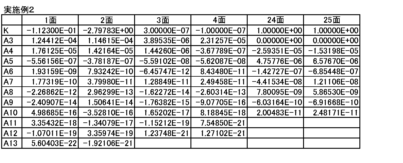
- Table 3 shows the basic lens data of the projection wide-angle lens of Example 2, the distance between the lens groups when the projection distance changes, and Table 4 shows the aspheric coefficient of each aspheric surface.
- Example 3 The configuration of the wide-angle lens for projection in Example 3 is as shown in FIG.
- the wide-angle lens for projection in Example 3 has substantially the same configuration as the wide-angle lens for projection in Example 1 described above, but the lens L1 has a negative meniscus shape with a convex surface facing the enlargement side in the paraxial region. The difference is that the lens L2 has a negative meniscus shape with a convex surface facing the reduction side in the paraxial region, and the lens L12 has a biconvex shape.
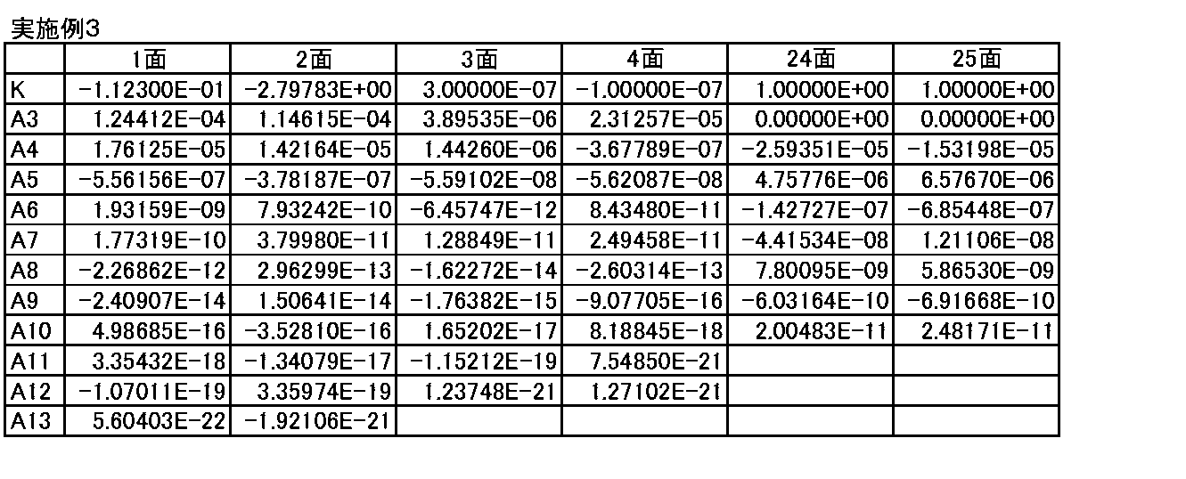
- Table 5 shows the basic lens data of the projection wide-angle lens of Example 3, the distance between the lens groups when the projection distance is changed, and Table 6 shows the aspheric coefficient of each aspheric surface.
- Example 4 The configuration of the wide-angle lens for projection in Example 4 is as shown in FIG.
- the wide-angle lens for projection in Example 4 has substantially the same configuration as the wide-angle lens for projection in Example 1 described above, but the lens L1 has a negative meniscus shape with a convex surface facing the enlargement side in the paraxial region.
- the difference is that the lens L2 has a negative meniscus shape with a convex surface facing the reduction side in the paraxial region, the lens L9 has a biconvex shape, and the lens L15 has a biconcave shape.
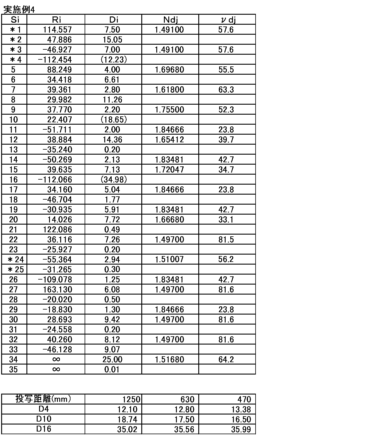
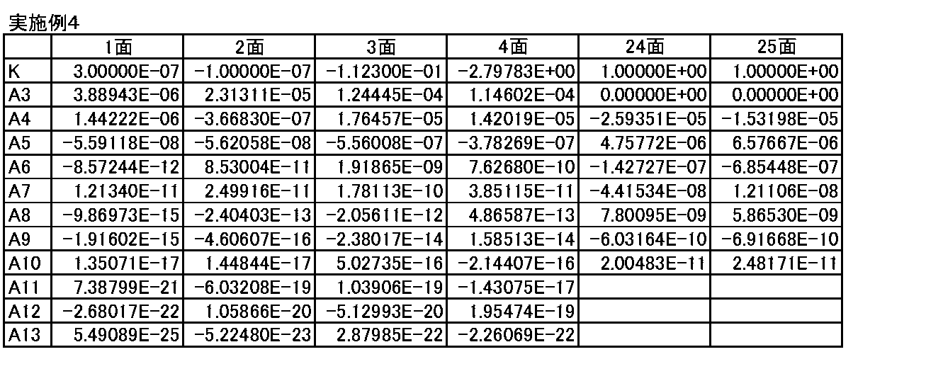
- Table 7 shows the basic lens data of the wide-angle lens for projection in Example 4, the distance between the lens groups when the projection distance changes, and Table 8 shows the aspheric coefficient of each aspheric surface.
- Example 5 The configuration of the wide-angle lens for projection in Example 5 is as shown in FIG.
- the wide-angle lens for projection of Example 5 includes, in order from the magnification side, a first lens group G1 having a negative refractive power, a second lens group G2 having a negative refractive power, and a third lens group G3 having a negative refractive power.
- the fourth lens group G4 having a positive refractive power is arranged.
- the reduction side of the projection wide-angle lens is substantially telecentric.
- a glass block (including a filter unit) 2 mainly including a color synthesis prism and an image display surface 1 of a light valve are disposed.
- the first lens group G1 includes, in order from the magnification side, a negative meniscus lens L1 having a convex surface facing the magnification side in the paraxial region and a negative meniscus lens L2 having a convex surface facing the reduction side in the paraxial region. It is arranged and configured. Both the lens L1 and the lens L2 have aspheric surfaces on both sides.
- the second lens group G2 includes three negative meniscus lenses L3 to L5 having a convex surface facing the enlargement side.
- the third lens group G3 includes, in order from the magnification side, a biconcave lens L6, a biconvex lens L7, a positive meniscus lens L8 with a convex surface facing the reduction side, a biconcave lens L9, and A cemented lens obtained by cementing biconvex lenses L10 is arranged.
- the fourth lens group G4 includes, in order from the magnifying side, a positive meniscus lens L11 having a convex surface on the magnifying side, a cemented lens in which a biconcave lens L12 and a biconvex lens L13 are cemented, and a biconvex shape.
- Lens L14 a positive meniscus lens L15 having a convex surface facing the reduction side in the paraxial region, a cemented lens in which a biconcave lens L16 and a biconvex lens L17 are cemented, and a biconcave lens L18.
- a cemented lens obtained by cementing a biconvex lens L19 and a biconvex lens L20 are arranged.
- the lens L15 has two aspheric surfaces.
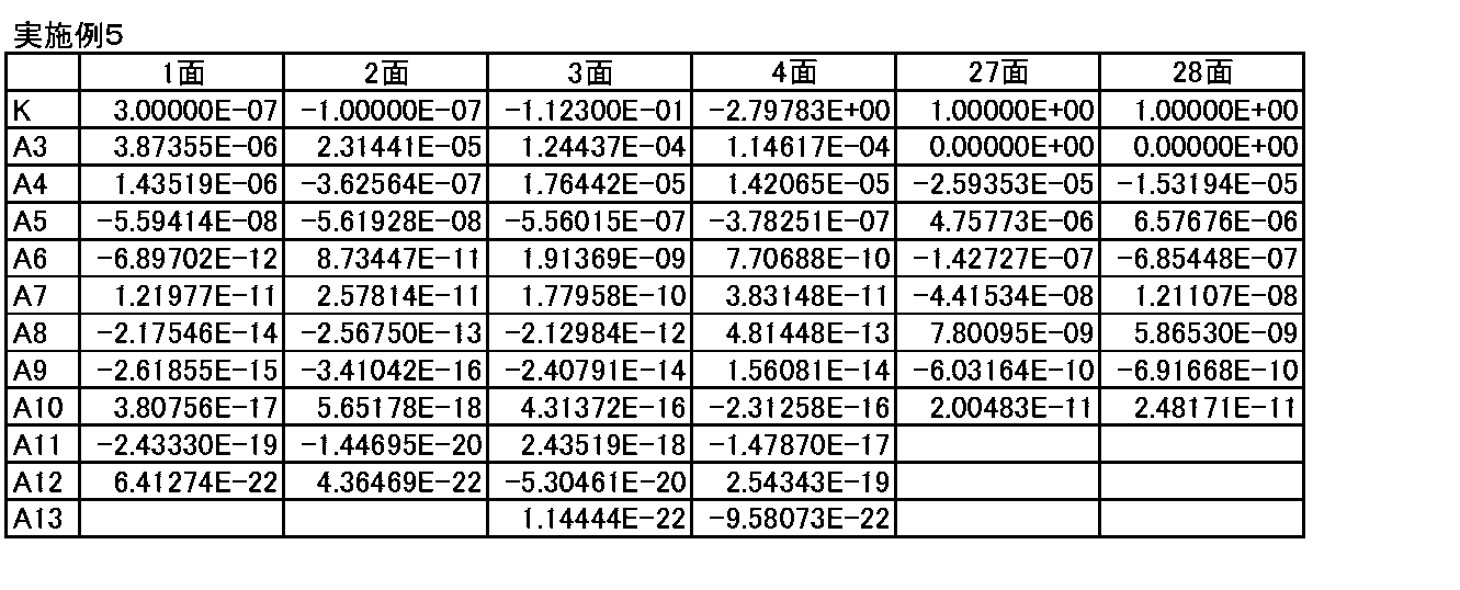
- Table 9 shows the basic lens data of the projection wide-angle lens of Example 5, the interval between the lens groups when the projection distance changes, and Table 10 shows the aspheric coefficient of each aspheric surface.
- Example 6 The configuration of the wide-angle lens for projection of Example 6 is as shown in FIG.
- the wide-angle lens for projection of Example 6 has substantially the same configuration as the wide-angle lens for projection of Example 5 described above, but has a point that a biconcave lens L8 and a biconvex lens L9 are cemented,
- the lens L10 is a single lens and has a positive meniscus shape with a convex surface facing the reduction side, and the configuration of the fourth lens group G4 is different.
- the fourth lens group G4 of Example 6 includes, in order from the enlargement side, a biconvex lens L11, a biconcave lens L12, a biconvex lens L13, and a positive meniscus shape having a convex surface facing the enlargement side.
- the lens L18, the biconvex lens L19, and the biconvex lens L20 are arranged.
- the lens L12 and the lens L13 are cemented.
- the lenses L16 to L19 are cemented.
- the lens L15 has two aspheric surfaces.
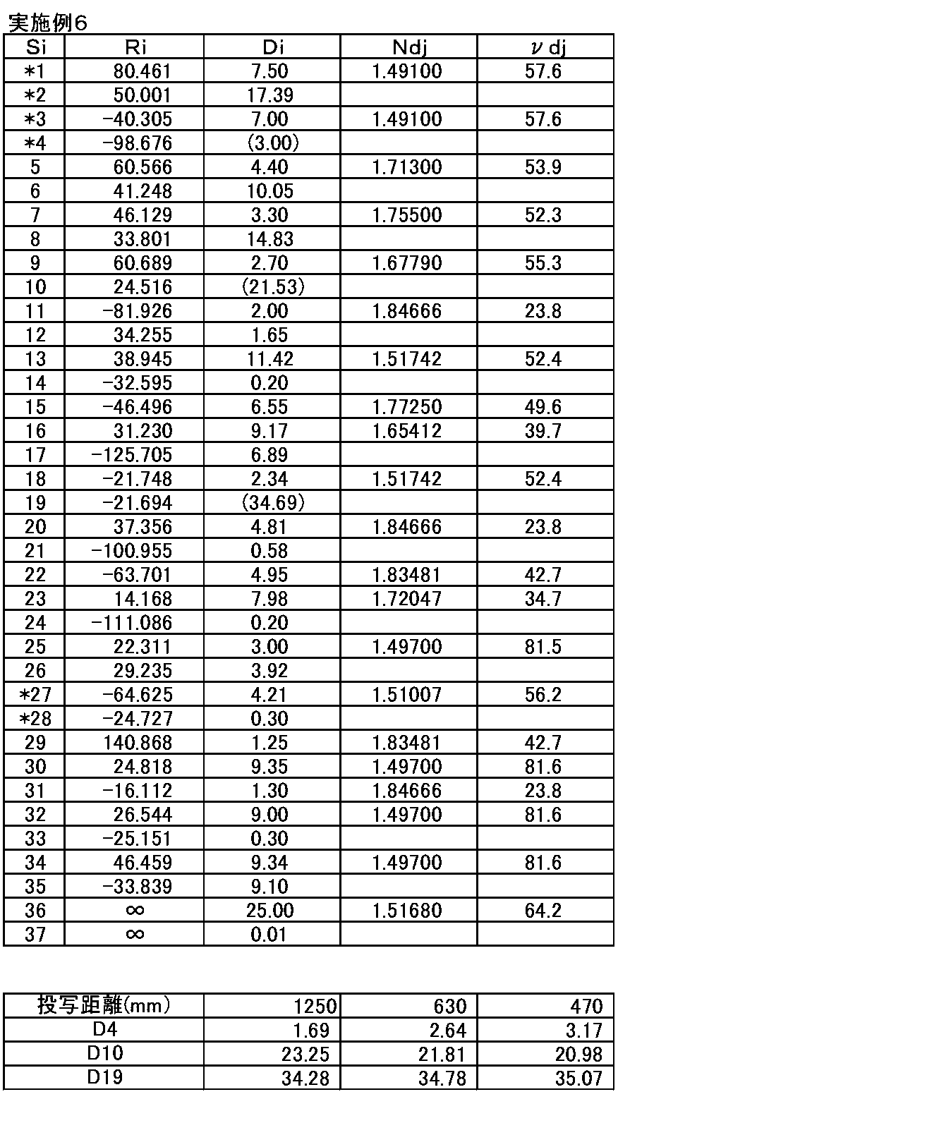
- Table 11 shows the basic lens data of the wide-angle lens for projection in Example 6, the distance between the lens groups when the projection distance changes, and Table 12 shows the aspheric coefficient of each aspheric surface.
- Example 7 The configuration of the wide-angle lens for projection of Example 7 is as shown in FIG.
- the wide-angle lens for projection in Example 7 includes, in order from the magnification side, a first lens group G1 having a negative refractive power, a second lens group G2 having a negative refractive power, and a third lens group G3 having a negative refractive power.
- the fourth lens group G4 having a positive refractive power is arranged.
- the reduction side of the projection wide-angle lens is substantially telecentric.
- a glass block (including a filter unit) 2 mainly including a color synthesis prism and an image display surface 1 of a light valve are disposed.
- the first lens group G1 includes, in order from the magnification side, a negative meniscus lens L1 having a convex surface facing the magnification side, a negative meniscus lens L2 having a convex surface facing the reduction side in the paraxial region, and a paraxial region.
- a negative meniscus lens L3 having a convex surface facing the enlargement side is arranged. Both the lens L2 and the lens L3 are aspheric on both sides.
- the second lens group G2 includes three negative meniscus lenses L4 to L6 having a convex surface facing the enlargement side.
- the third lens group G3 includes, in order from the enlargement side, a cemented lens obtained by cementing a biconcave lens L7 and a biconvex lens L8, a biconcave lens L9, and a positive meniscus shape having a convex surface facing the enlargement side.
- a cemented lens in which the lens L10 is cemented is arranged.
- the fourth lens group G4 includes, in order from the enlargement side, a biconvex lens L11, a biconcave lens L12, a cemented lens in which a positive meniscus lens L13 having a convex surface facing the enlargement side, and a biconvex shape.
- a cemented lens obtained by cementing a biconcave lens L18 and a biconvex lens L19 and a biconvex lens L20 are arranged.
- the lens L15 has two aspheric surfaces.
- Table 13 shows the basic lens data of the wide-angle lens for projection in Example 7, the distance between the lens groups when the projection distance changes, and Table 14 shows the aspheric coefficient of each aspheric surface.
- Table 15 shows the specifications of Examples 1 to 7, the values related to conditional expressions (1) to (6), and the corresponding values.
- Fno in Table 15 is the F number, and the total length is the distance on the optical axis from the most magnified lens surface to the reduction-side image surface when the projection distance is infinite (the back focus component is the air equivalent distance).
- Each value shown in Table 15 is for the e line.
- FIGS. 8A to 8D show aberration diagrams of the spherical aberration, astigmatism, distortion (distortion aberration), and lateral chromatic aberration (chromatic aberration of magnification) of the projection wide-angle lens of Example 1, respectively.
- Each aberration diagram relates to the e-line (wavelength 546 nm), but the spherical aberration diagram also shows aberrations relating to the wavelength 460 nm and the wavelength 610 nm.
- aberrations in the sagittal direction and the tangential direction are indicated by a solid line and a broken line, respectively.
- the lateral chromatic aberration diagram shows aberrations with respect to a wavelength of 460 nm and a wavelength of 610 nm.
- Fno Described above the vertical axis in FIG. Represents the F number, and ⁇ described above the vertical axis in FIGS. 8B to 8D represents a half angle of view.
- FIGS. 9 (A) to 9 (E) show transverse aberration diagrams at half angles of view in the tangential direction of the wide-angle lens for projection of Example 1
- FIGS. 9 (F) to 9 (I) show the results.
- FIG. 3 shows lateral aberration diagrams in the sagittal direction at each half field angle of the wide-angle lens for projection of Example 1.
- FIG. The horizontal aberrations in the tangential direction and the sagittal direction with the same half field angle are shown in the horizontal direction, and the numerical values described between the lateral aberrations in these two directions indicate the half field angles.
- the aberration diagrams shown in FIGS. 8 (A) to 8 (D) and FIGS. 9 (A) to 9 (I) are for the projection distance infinite.
- FIGS. 10A to 10D, FIGS. 11A to 11I, and FIGS. 12A to 12 are aberration diagrams of the wide-angle lenses for projection in Examples 2 to 7, respectively.
- FIGS. 20 (A) to 20 (D) It is shown in FIGS. 21 (A) to 21 (I). From each aberration diagram, it can be seen that the projection wide-angle lenses of Examples 1 to 7 have each aberration corrected satisfactorily.
- the present invention has been described with reference to the embodiments and examples.
- the present invention is not limited to the above-described embodiments and examples, and various modifications can be made.
- the values of the radius of curvature, the surface interval, the refractive index, the Abbe number, and the aspheric coefficient of each lens of the wide angle lens for projection according to the present invention can be changed as appropriate.
- the light valve used in the projection display device of the present invention and the optical member used for light beam separation or light beam synthesis are not limited to the above-described configuration, and various modifications can be made.
Landscapes
- Physics & Mathematics (AREA)
- General Physics & Mathematics (AREA)
- Optics & Photonics (AREA)
- Lenses (AREA)
Abstract
【課題】投写用広角レンズにおいて、全画角130度以上の広角、小さなFナンバー、長いバックフォーカスを有し、小型化と低コスト化を図り、諸収差を良好に補正する。 【解決手段】拡大側から順に、2枚の非球面レンズを含む第1レンズ群(G1)と、拡大側に凸面を向けた3枚の負メニスカスレンズからなる第2レンズ群(G2)と、少なくとも1つの接合レンズを含み、負の屈折力を有する第3レンズ群(G3)と、少なくとも2つの接合レンズと1枚の非球面レンズを含み、正の屈折力を有する第4レンズ群(G4)とを配列してなる。全系の隣り合うレンズ群の間隔のうち第3レンズ群(G3)と第4レンズ群(G4)の間隔が最長である。第1レンズ群(G1)から第3レンズ群(G3)までの合成焦点距離、全系の焦点距離、第4レンズ群(G4)の焦点距離、バックフォーカスに関する所定の条件式を満たす。
Description
本発明は、投写用広角レンズおよび投写型表示装置に関し、特に、液晶表示素子やDMD(デジタル・マイクロミラー・デバイス:登録商標)等のライトバルブを搭載したプロジェクタ装置に用いられるのに好適な投写用広角レンズおよびこれを用いた投写型表示装置に関する。
従来、液晶表示素子やDMD等のライトバルブを用いた、投写プロジェクタ装置(投写型表示装置)が広く普及している。このような投写型表示装置に用いられる投写用レンズには、Fナンバーが小さいこと、色合成プリズム等を配置できるように長いバックフォーカスを有すること、縮小側がほぼテレセントリックであること、ライトバルブの解像度に見合った高い光学性能を有することが求められる。従来知られている投写用レンズとしては、例えば下記特許文献1~3に記載のものがある。
ところで、近年では投写用レンズに対して広角化に対する要求が強まってきており、例えば全画角が130度以上の広い画角を有するものが望まれるようになってきている。上記特許文献1~3に記載のものは、広角を意識したものであるが、いずれも全画角が130度以上の広角に対応したものとはいえない。
本発明は、上記事情に鑑みなされたものであり、全画角が130度以上となる広い画角を有し、Fナンバーが小さく、バックフォーカスが長く、小型化と低コスト化が図られ、諸収差が良好に補正された投写用広角レンズおよびこれを用いた投写型表示装置を提供することを目的とするものである。
本発明の投写用広角レンズは、拡大側から順に、2枚の非球面レンズを含む第1レンズ群と、拡大側に凸面を向けた3枚の負メニスカスレンズからなる第2レンズ群と、少なくとも1組の接合レンズを含み、負の屈折力を有する第3レンズ群と、少なくとも2つの接合レンズと1枚の非球面レンズを含み、正の屈折力を有する第4レンズ群とからなり、全系の隣り合うレンズ群の間隔のうち第3レンズ群と第4レンズ群の間隔が最長となるように構成されており、下記条件式(1)~(3)を満たすことを特徴とするものである。
-3.8<f123/f<-1.6 … (1)
6.6<f4/f<11.5 … (2)
5.1<Bf/f<6.4 … (3)
ただし、
f123:第1レンズ群から第3レンズ群までの合成焦点距離
f:全系の焦点距離
f4:第4レンズ群の焦点距離
Bf:縮小側のバックフォーカス(空気換算距離)
-3.8<f123/f<-1.6 … (1)
6.6<f4/f<11.5 … (2)
5.1<Bf/f<6.4 … (3)
ただし、
f123:第1レンズ群から第3レンズ群までの合成焦点距離
f:全系の焦点距離
f4:第4レンズ群の焦点距離
Bf:縮小側のバックフォーカス(空気換算距離)
本発明の投写用広角レンズにおいては、下記条件式(4)~(6)の少なくとも1つ、または任意の組合せを満たすことが好ましい。
2.0<f2/f123<3.8 … (4)
4.8<f3/123<11.3 … (5)
4.0<d3-4/f<12.0 … (6)
ただし、
f2:第2レンズ群の焦点距離
f3:第3レンズ群の焦点距離
d3-4:投写距離が無限遠のときの第3レンズ群と第4レンズ群の光軸上の間隔
2.0<f2/f123<3.8 … (4)
4.8<f3/123<11.3 … (5)
4.0<d3-4/f<12.0 … (6)
ただし、
f2:第2レンズ群の焦点距離
f3:第3レンズ群の焦点距離
d3-4:投写距離が無限遠のときの第3レンズ群と第4レンズ群の光軸上の間隔
また、本発明の投写用広角レンズにおいては、第4レンズ群が、d線におけるアッベ数が80以上の材質からなる正レンズを3枚以上含むことが好ましい。
また、本発明の投写用広角レンズにおいては、投写距離が変化したときのフォーカス調整は、第2レンズ群および第3レンズ群のみを光軸方向に移動させることにより行い、投写距離が遠方から近方に変化したときのフォーカス調整の際に、第2レンズ群は縮小側へ、第3レンズ群は拡大側へ移動するように構成されていることが好ましい。
本発明の投写型表示装置は、光源と、ライトバルブと、該光源からの光束を該ライトバルブへ導く照明光学部と、上記記載の投写用広角レンズとを備え、光源からの光束をライトバルブにより光変調し、上記記載の投写用広角レンズによりスクリーンに投写することを特徴とするものである。
なお、上記「拡大側」とは、被投写側(スクリーン側)を意味し、縮小投影する場合も、便宜的にスクリーン側を拡大側と称するものとする。一方、上記「縮小側」とは、原画像表示領域側(ライトバルブ側)を意味し、縮小投影する場合も、便宜的にライトバルブ側を縮小側と称するものとする。
なお、上記本発明の投写用広角レンズにおけるレンズの面形状、屈折力の符号は、非球面が含まれているものについては近軸領域で考えるものとする。
なお、「レンズ群」とは、必ずしも複数のレンズから構成されるものだけでなく、1枚のレンズのみで構成されるものも含むものとする。
本発明によれば、4群構成の投写用広角レンズにおいて、各レンズ群の構成を好適に設定し、条件式(1)~(3)を満たすように構成しているため、全画角が130度以上となる広い画角を確保し、Fナンバーが小さく、長いバックフォーカスを有し、小型化と低コスト化が図られ、諸収差が良好に補正された投写用広角レンズおよびこれを用いた投写型表示装置を提供することができる。
以下、本発明の実施形態について図面を参照して詳細に説明する。図1~図7は、本発明の実施形態にかかる投写用広角レンズの構成例を示す断面図であり、それぞれ後述の実施例1~7の投写用広角レンズに対応している。図1~図7に示す例の基本的な構成は同様であり、図示方法も同様であるため、ここでは主に図1を参照しながら、本発明の実施形態にかかる投写用広角レンズについて説明する。
図1に示す本実施形態にかかる投写用広角レンズは、光軸Z1に沿って、拡大側(図中矢印-Zで示す側)から縮小側(図中矢印+Zで示す側)へ順に、第1レンズ群G1と、第2レンズ群G2と、第3レンズ群G3と、第4レンズ群G4との4つのレンズ群を配列して構成される。なお、図1には投写用広角レンズの縮小側に、色合成プリズムを主とするガラスブロック(フィルタ部を含む)2と、液晶表示素子やDMD等のライトバルブの画像表示面1とを配設した例を示している。
第1レンズ群G1は、2枚の非球面レンズを含むように構成される。最も拡大側の第1レンズ群G1が少なくとも2枚の非球面レンズを含むことで、広角化と小さなFナンバーの実現に有利となる。非球面レンズは少なくとも1面の非球面を有していればよいが、両面とも非球面とすることで良好な収差補正に有利となる。
第1レンズ群G1は、広角化のためには負の屈折力を有することが好ましい。例えば図1に示す第1レンズ群G1は、近軸領域で負メニスカス形状の2枚のレンズL1、L2からなる。このように、第1レンズ群G1が近軸領域で負メニスカス形状の2枚のレンズを有する場合、いずれか一方が近軸領域で物体側に凸面を向け、他方が近軸領域で像側に凸面を向けた形状とすることが好ましい。
なお、第1レンズ群G1は、小型化や低コスト化を重視する場合は上記のように2枚構成とすることが好ましいが、保護機能を兼備させたレンズをさらに拡大側に配置した3枚構成としてもよい。
第2レンズ群G2は、全体として負の屈折力を有するレンズ群である。第2レンズ群G2は、図1に示すように、拡大側に凸面を向けた3枚の負メニスカスレンズL3、L4、L5からなるように構成される。これにより、第2レンズ群G2の負の屈折力を負メニスカス形状の3枚の単レンズに分散させることができ、緩やかに光線を曲げて、コマ収差、像面湾曲の発生を抑制することができる。
第3レンズ群G3は、全体として負の屈折力を有するレンズ群である。第3レンズ群G3は、正レンズと負レンズが接合された少なくとも1つの接合レンズを含むように構成される。第3レンズ群G3が接合レンズを含むことで、軸上色収差および倍率色収差を良好に補正することが可能となる。第3レンズ群G3が2つの接合レンズを含む場合は、軸上色収差および倍率色収差の補正にさらに有利となる。
例えば図1に示す第3レンズ群G3は、拡大側から順に、両凹レンズであるレンズL6および両凸レンズであるレンズL7を接合した接合レンズと、両凹レンズであるレンズL8および正レンズであるレンズL9を接合した接合レンズとが配列された4枚構成である。しかし、第3レンズ群G3は、両凹レンズと、両凸レンズと、正メニスカスレンズと、両凹レンズおよび両凸レンズを接合した接合レンズとからなる5枚構成としてもよい。第3レンズ群G3が少なくとも2枚の正レンズと少なくとも2枚の負レンズを含むことで、軸上色収差および倍率色収差を良好に補正することが可能となる。
第4レンズ群G4は、全体として正の屈折力を有するレンズ群である。第4レンズ群G4は、少なくとも2つの接合レンズと1枚の非球面レンズを含むように構成される。第4レンズ群G4が含む接合レンズは、少なくとも1枚の正レンズと少なくとも1枚の負レンズが接合されたものとなる。第4レンズ群G4が少なくとも2つの接合レンズを含むことで、軸上色収差および倍率色収差を良好に補正することが可能となる。第4レンズ群G4は、正レンズと負レンズが接合された接合面を3面以上有することが好ましく、このように構成した場合は、軸上色収差および倍率色収差の補正にさらに有利となる。また、第4レンズ群G4が非球面レンズを含むことで、諸収差を良好に補正することが可能となる。
さらに、第4レンズ群は、d線におけるアッベ数が80以上の材質からなる正レンズを3枚以上含むことが好ましい。正レンズ群である第4レンズ群G4が、少なくとも2つの接合レンズと1枚の非球面レンズを含み、さらにアッベ数が80以上の正レンズを3枚以上含むことにより、バックフォーカスの確保、レンズ系全体の大きさの最適化、軸上色収差と倍率色収差を含めた諸収差の良好な補正を同時に実現することが可能になる。
第4レンズ群G4は、例えば図1に示す例のように、拡大側から順に、両凸レンズであるレンズL10と、両凹レンズであるレンズL11および正レンズであるレンズL12を接合した接合レンズと、両凸レンズであるレンズL13と、近軸領域で正メニスカス形状のレンズL14と、負メニスカスレンズであるレンズL15および両凸レンズであるレンズL16を接合した接合レンズと、両凹レンズであるレンズL17および両凸レンズであるレンズL18を接合した接合レンズと、両凸レンズであるレンズL19とからなる10枚構成とすることができる。
第3レンズ群G3と第4レンズ群G4の光軸上の間隔は、全系の隣り合うレンズ群の光軸上の間隔のうち、最も長くなるように構成されている。これにより、第3レンズ群G3と第4レンズ群G4の間に、絞りや光束分割/合成部材等を配置することが容易になる。
また、本実施形態にかかる投写用広角レンズは、下記条件式(1)~(3)を満たすように構成されている。
-3.8<f123/f<-1.6 … (1)
6.6<f4/f<11.5 … (2)
5.1<Bf/f<6.4 … (3)
ただし、
f123:第1レンズ群G1から第3レンズ群G3までの合成焦点距離
f:全系の焦点距離
f4:第4レンズ群G4の焦点距離
Bf:縮小側のバックフォーカス(空気換算距離)
-3.8<f123/f<-1.6 … (1)
6.6<f4/f<11.5 … (2)
5.1<Bf/f<6.4 … (3)
ただし、
f123:第1レンズ群G1から第3レンズ群G3までの合成焦点距離
f:全系の焦点距離
f4:第4レンズ群G4の焦点距離
Bf:縮小側のバックフォーカス(空気換算距離)
本実施形態のような広角レンズでは第1レンズ群G1から第3レンズ群G3までの合成屈折力は負となる。条件式(1)の下限を下回ると、第1レンズ群G1から第3レンズ群G3までの合成焦点距離が長くなり、第1レンズ群G1から第3レンズ群G3までの合成屈折力が弱くなるため、バックフォーカスの確保が困難となる。条件式(1)の上限を上回ると、第1レンズ群G1から第3レンズ群G3までの合成焦点距離が短くなり、コマ収差、像面湾曲、非点隔差の発生量が大きくなり、収差を良好に補正することが困難となる。
条件式(2)の下限を下回ると、第4レンズ群G4の焦点距離が短くなり、バックフォーカスの確保、諸収差の補正が困難となる。条件式(2)の上限を上回ると、レンズ系全体の大型化を招き、また大径化によりコストアップとなる。
条件式(3)の下限を下回ると、バックフォーカスが短くなり、色合成プリズム等を配置するのが困難になる。バックフォーカスを十分確保したうえで、条件式(3)の上限を上回ると、全系の焦点距離が短くなり、諸収差の補正が困難となる。
さらに本実施形態の投写用広角レンズにおいては、以下に述べる構成を適宜選択的に有することが好ましい。なお、好ましい態様としては、以下に述べる構成の1つを有するものでもよく、あるいは任意の複数の組合せを有するものでもよい。
下記条件式(4)を満たすことが好ましい。
2.0<f2/f123<3.8 … (4)
ただし、
f2:第2レンズ群G2の焦点距離
f123:第1レンズ群G1から第3レンズ群G3までの合成焦点距離
2.0<f2/f123<3.8 … (4)
ただし、
f2:第2レンズ群G2の焦点距離
f123:第1レンズ群G1から第3レンズ群G3までの合成焦点距離
条件式(4)の下限を下回ると、コマ収差、像面湾曲の発生量が大きくなる。条件式(4)の上限を上回ると、第1レンズ群G1の最も拡大側のレンズの径が大きくなる。
下記条件式(5)を満たすことが好ましい。
4.8<f3/123<11.3 … (5)
ただし、
f3:第3レンズ群G3の焦点距離
f123:第1レンズ群G1から第3レンズ群G3までの合成焦点距離
4.8<f3/123<11.3 … (5)
ただし、
f3:第3レンズ群G3の焦点距離
f123:第1レンズ群G1から第3レンズ群G3までの合成焦点距離
条件式(5)の下限を下回ると、第1レンズ群G1、第2レンズ群G2の大型化を招き、また大径化によりコストアップとなる。条件式(5)の上限を上回ると、バックフォーカスの確保が困難となる。
下記条件式(6)を満たすことが好ましい。
4.0<d3-4/f<12.0 … (6)
ただし、
d3-4:投写距離が無限遠のときの第3レンズ群G3と第4レンズ群G4の光軸上の間隔
f:全系の焦点距離
4.0<d3-4/f<12.0 … (6)
ただし、
d3-4:投写距離が無限遠のときの第3レンズ群G3と第4レンズ群G4の光軸上の間隔
f:全系の焦点距離
条件式(6)は全系のなかで最長のレンズ群間隔に関する式である。条件式(6)の下限を下回ると、諸収差の良好な補正、バックフォーカスの確保が困難となる。条件式(6)の上限を上回ると、レンズ系の大型化を招く。
上記事情から、上記条件式(1)~(6)それぞれに代えて下記条件式(1-1)~(6-1)それぞれを満たすことがより好ましい。
-3.2<f123/f<-1.8 … (1-1)
7.2<f4/f<9.4 … (2-1)
5.2<Bf/f<5.9 … (3-1)
2.2<f2/f123<3.2 … (4-1)
5.4<f3/123<9.6 … (5-1)
4.4<d3-4/f<9.8 … (6-1)
-3.2<f123/f<-1.8 … (1-1)
7.2<f4/f<9.4 … (2-1)
5.2<Bf/f<5.9 … (3-1)
2.2<f2/f123<3.2 … (4-1)
5.4<f3/123<9.6 … (5-1)
4.4<d3-4/f<9.8 … (6-1)
また、本実施形態の投写用広角レンズにおいては、第2レンズ群G2および第3レンズ群G3を光軸方向に移動させることによりフォーカス調整が行われるように構成し、投写距離が遠距離から近距離に変化した際のフォーカス調整は、第2レンズ群G2を縮小側へ、第3レンズ群G3を拡大側へ移動させて行うように構成することが好ましい。この方式によれば、レンズ系全体を移動させてフォーカス調整を行う方式、または径の大きいレンズからなる第1レンズ群G1を含むレンズ群を移動させてフォーカス調整を行う方式に比べて、フォーカス機構を簡素化することができ、コストダウンが図ることができる。
また、本実施形態にかかる投写用広角レンズが投写型表示装置に搭載された際に、ライトバルブとして液晶表示素子を用いたり、投写用広角レンズの縮小側に光束分離光学系や光束合成光学系としてPBS(Polarized Beam Splitter)プリズムや色合成プリズムを配置したりすることがあるため、本実施形態の投写用広角レンズは、縮小側がテレセントリックとされていることが好ましい。
以上述べた本実施形態の投写用広角レンズによれば、130度以上の広い画角を持ち、FナンバーもF1.8~F2.0と小さく、縮小側がほぼテレセントリックで、長いバックフォーカスを有し、小型化および低コスト化が図られ、諸収差が良好に補正された投射用レンズを実現することが可能となる。
次に、上述した投写用広角レンズを搭載した投写型表示装置について説明する。図22は本発明の一実施形態にかかる投写型表示装置の概略構成図である。
図22に示す投写型表示装置は、光源20と、各色光に対応したライトバルブとしての透過型液晶表示パネル11a~11cと、光源20からの光束をライトバルブへ導く照明光学部30とを備えている。照明光学部30は、色分解のためのダイクロイックミラー12、13と、色合成のためのクロスダイクロイックプリズム14と、コンデンサレンズ16a~16cと、全反射ミラー18a~18cとを有する。なお、図22では光源20とダイクロイックミラー12の間の構成は図示を省略している。
光源20からの白色光は、照明光学部30において、ダイクロイックミラー12、13で3つの色光光束(G光、B光、R光)に分解された後、それぞれ全反射ミラー18a~18cにより光路を偏向されてコンデンサレンズ16a~16cを経て各色光光束にそれぞれ対応する透過型液晶表示パネル11a~11cに入射して光変調され、クロスダイクロイックプリズム14により色合成された後、投写用広角レンズ10に入射して、投写用広角レンズ10により図示されていないスクリーンに投写される。なお、図22では、投写用広角レンズ10は概略的に図示している。
次に、本発明の投写用広角レンズの数値実施例について説明する。
<実施例1>
実施例1の投写用広角レンズの構成は図1に示したとおりである。実施例1の投写用広角レンズは、拡大側から順に、負の屈折力を有する第1レンズ群G1、負の屈折力を有する第2レンズ群G2、負の屈折力を有する第3レンズ群G3、正の屈折力を有する第4レンズ群G4を配列してなる。投写用広角レンズの縮小側は略テレセントリックに構成されている。投写用広角レンズの縮小側には、色合成プリズムを主とするガラスブロック(フィルタ部を含む)2およびライトバルブの画像表示面1が配設されている。
実施例1の投写用広角レンズの構成は図1に示したとおりである。実施例1の投写用広角レンズは、拡大側から順に、負の屈折力を有する第1レンズ群G1、負の屈折力を有する第2レンズ群G2、負の屈折力を有する第3レンズ群G3、正の屈折力を有する第4レンズ群G4を配列してなる。投写用広角レンズの縮小側は略テレセントリックに構成されている。投写用広角レンズの縮小側には、色合成プリズムを主とするガラスブロック(フィルタ部を含む)2およびライトバルブの画像表示面1が配設されている。
第1レンズ群G1は、拡大側から順に、近軸領域で縮小側に凸面を向けた負メニスカス形状のレンズL1と、近軸領域で拡大側に凸面を向けた負メニスカス形状のレンズL2とが配列されて構成されている。レンズL1、レンズL2はともに両側の面が非球面である。
第2レンズ群G2は、拡大側に凸面を向けた3枚の負メニスカス形状のレンズL3~L5からなる。
第3レンズ群G3は、拡大側から順に、両凹形状のレンズL6および両凸形状のレンズL7を接合した接合レンズと、両凹形状のレンズL8および拡大側に凸面を向けた正メニスカス形状のレンズL9を接合した接合レンズとが配列されて構成されている。
第4レンズ群G4は、拡大側から順に、両凸形状のレンズL10と、両凹形状のレンズL11および拡大側に凸面を向けた正メニスカス形状のレンズL12を接合した接合レンズと、両凸形状のレンズL13と、近軸領域で縮小側に凸面を向けた正メニスカス形状のレンズL14と、拡大側に凸面を向けた負メニスカス形状のレンズL15および両凸形状のレンズL16を接合した接合レンズと、両凹形状のレンズL17および両凸形状のレンズL18を接合した接合レンズと、両凸形状のレンズL19とが配列されて構成されている。レンズL14は両側の面が非球面である。
この投写用広角レンズにおいては、第2レンズ群G2および第3レンズ群G3を光軸方向に移動させることによりフォーカス調整が行われるように構成され、投写距離が遠距離から近距離に変化した際のフォーカス調整は、第2レンズ群G2を縮小側へ、第3レンズ群G3を拡大側へ移動させて行うように構成されている。
表1の上段に実施例1の投写用広角レンズの基本レンズデータを示す。表1にはガラスブロックも含めて示している。表1において、Siの欄には最も拡大側の構成要素(レンズ、ガラスブロック)の拡大側の面を1番目として縮小側に向かうに従い順次増加するように構成要素に面番号を付したときのi番目(i=1、2、3、…)の面番号を示す。Riの欄にはi番目の面の曲率半径を示し、Diの欄にはi番目の面とi+1番目の面との光軸Z1上の面間隔を示している。また、Ndjの欄には最も拡大側の構成要素を1番目として縮小側に向かうに従い順次増加するj番目(j=1、2、3、…)の構成要素のd線(波長587.6nm)に対する屈折率を示し、νdjの欄にはj番目の構成要素のd線に対するアッベ数を示している。
ただし、曲率半径の符号は、面形状が拡大側に凸の場合を正、縮小側に凸の場合を負としている。Diの欄の最下欄の値はガラスブロックの縮小側の面から画像表示面1までの距離である。第1レンズ群G1と第2レンズ群G2の間隔、第2レンズ群G2と第3レンズ群G3の間隔、第3レンズ群G3と第4レンズ群G4の間隔は、投写距離に応じて変化するものであり、これらの間隔に相当するそれぞれD4、D10、D16の欄には投写距離が無限遠のときの値を括弧書きで記入している。表1の下段に投写距離が1250mm、630mm、460mmのときのD4、D10、D16それぞれの値を示す。
表1の基本レンズデータの表において、面番号に*印が付いた面は非球面であり、非球面の曲率半径の欄には近軸の曲率半径の数値を示している。表2に、実施例1の投写用広角レンズの各非球面の非球面係数を示す。表2の非球面係数の数値の「E-n」(n:整数)は「×10-n」を意味し、「E+n」は「×10n」を意味する。非球面係数は、下式で表される非球面式における各係数K、Am(m=3、4、5、…)の値である。

ただし、
Zd:光軸から距離Yの非球面上の点より非球面頂点の接平面(光軸に垂直な平面)に下ろした垂線の長さ
Y:光軸からの距離
C:光軸近傍の曲率
K、Am:非球面係数(m=3、4、5、…)
Zd:光軸から距離Yの非球面上の点より非球面頂点の接平面(光軸に垂直な平面)に下ろした垂線の長さ
Y:光軸からの距離
C:光軸近傍の曲率
K、Am:非球面係数(m=3、4、5、…)

なお、基本レンズデータの長さの単位としてここではmmを用いているが、光学系は比例拡大又は比例縮小しても使用可能なため他の適当な単位を用いることも可能である。また、全ての表において所定の桁でまるめた数値を記載している。上述した各表の記号、意味、記載方法は以下の実施例2~7に対応する表3~14についても基本的に同様であるため、以下の表3~14については重複説明を省略する。
<実施例2>
実施例2の投写用広角レンズの構成は図2に示したとおりである。実施例2の投写用広角レンズは、上述の実施例1の投写用広角レンズと略同様の構成であるが、レンズL9が両凸形状である点において相違している。実施例2の投写用広角レンズの基本レンズデータ、投写距離が変化したときの各レンズ群の間隔を表3に示し、各非球面の非球面係数を表4に示す。
実施例2の投写用広角レンズの構成は図2に示したとおりである。実施例2の投写用広角レンズは、上述の実施例1の投写用広角レンズと略同様の構成であるが、レンズL9が両凸形状である点において相違している。実施例2の投写用広角レンズの基本レンズデータ、投写距離が変化したときの各レンズ群の間隔を表3に示し、各非球面の非球面係数を表4に示す。

<実施例3>
実施例3の投写用広角レンズの構成は図3に示したとおりである。実施例3の投写用広角レンズは、上述の実施例1の投写用広角レンズと略同様の構成であるが、レンズL1が近軸領域で拡大側に凸面を向けた負メニスカス形状である点と、レンズL2が近軸領域で縮小側に凸面を向けた負メニスカス形状である点と、レンズL12が両凸形状である点とにおいて相違している。実施例3の投写用広角レンズの基本レンズデータ、投写距離が変化したときの各レンズ群の間隔を表5に示し、各非球面の非球面係数を表6に示す。
実施例3の投写用広角レンズの構成は図3に示したとおりである。実施例3の投写用広角レンズは、上述の実施例1の投写用広角レンズと略同様の構成であるが、レンズL1が近軸領域で拡大側に凸面を向けた負メニスカス形状である点と、レンズL2が近軸領域で縮小側に凸面を向けた負メニスカス形状である点と、レンズL12が両凸形状である点とにおいて相違している。実施例3の投写用広角レンズの基本レンズデータ、投写距離が変化したときの各レンズ群の間隔を表5に示し、各非球面の非球面係数を表6に示す。

<実施例4>
実施例4の投写用広角レンズの構成は図4に示したとおりである。実施例4の投写用広角レンズは、上述の実施例1の投写用広角レンズと略同様の構成であるが、レンズL1が近軸領域で拡大側に凸面を向けた負メニスカス形状である点と、レンズL2が近軸領域で縮小側に凸面を向けた負メニスカス形状である点と、レンズL9が両凸形状である点と、レンズL15が両凹形状である点とにおいて相違している。実施例4の投写用広角レンズの基本レンズデータ、投写距離が変化したときの各レンズ群の間隔を表7に示し、各非球面の非球面係数を表8に示す。
実施例4の投写用広角レンズの構成は図4に示したとおりである。実施例4の投写用広角レンズは、上述の実施例1の投写用広角レンズと略同様の構成であるが、レンズL1が近軸領域で拡大側に凸面を向けた負メニスカス形状である点と、レンズL2が近軸領域で縮小側に凸面を向けた負メニスカス形状である点と、レンズL9が両凸形状である点と、レンズL15が両凹形状である点とにおいて相違している。実施例4の投写用広角レンズの基本レンズデータ、投写距離が変化したときの各レンズ群の間隔を表7に示し、各非球面の非球面係数を表8に示す。
<実施例5>
実施例5の投写用広角レンズの構成は図5に示したとおりである。実施例5の投写用広角レンズは、拡大側から順に、負の屈折力を有する第1レンズ群G1、負の屈折力を有する第2レンズ群G2、負の屈折力を有する第3レンズ群G3、正の屈折力を有する第4レンズ群G4を配列してなる。投写用広角レンズの縮小側は略テレセントリックに構成されている。投写用広角レンズの縮小側には、色合成プリズムを主とするガラスブロック(フィルタ部を含む)2およびライトバルブの画像表示面1が配設されている。
実施例5の投写用広角レンズの構成は図5に示したとおりである。実施例5の投写用広角レンズは、拡大側から順に、負の屈折力を有する第1レンズ群G1、負の屈折力を有する第2レンズ群G2、負の屈折力を有する第3レンズ群G3、正の屈折力を有する第4レンズ群G4を配列してなる。投写用広角レンズの縮小側は略テレセントリックに構成されている。投写用広角レンズの縮小側には、色合成プリズムを主とするガラスブロック(フィルタ部を含む)2およびライトバルブの画像表示面1が配設されている。
第1レンズ群G1は、拡大側から順に、近軸領域で拡大側に凸面を向けた負メニスカス形状のレンズL1と、近軸領域で縮小側に凸面を向けた負メニスカス形状のレンズL2とが配列されて構成されている。レンズL1、レンズL2はともに両側の面が非球面である。
第2レンズ群G2は、拡大側に凸面を向けた3枚の負メニスカス形状のレンズL3~L5からなる。
第3レンズ群G3は、拡大側から順に、両凹形状のレンズL6と、両凸形状のレンズL7と、縮小側に凸面を向けた正メニスカス形状のレンズL8と、両凹形状のレンズL9および両凸形状のレンズL10を接合した接合レンズとが配列されて構成されている。
第4レンズ群G4は、拡大側から順に、拡大側に凸面を向けた正メニスカス形状のレンズL11と、両凹形状のレンズL12および両凸形状のレンズL13を接合した接合レンズと、両凸形状のレンズL14と、近軸領域で縮小側に凸面を向けた正メニスカス形状のレンズL15と、両凹形状のレンズL16および両凸形状のレンズL17を接合した接合レンズと、両凹形状のレンズL18および両凸形状のレンズL19を接合した接合レンズと、両凸形状のレンズL20とが配列されて構成されている。レンズL15は両側の面が非球面である。
実施例5の投写用広角レンズの基本レンズデータ、投写距離が変化したときの各レンズ群の間隔を表9に示し、各非球面の非球面係数を表10に示す。

<実施例6>
実施例6の投写用広角レンズの構成は図6に示したとおりである。実施例6の投写用広角レンズは、上述の実施例5の投写用広角レンズと略同様の構成であるが、両凹形状のレンズL8および両凸形状のレンズL9が接合されている点と、レンズL10が単レンズで縮小側に凸面を向けた正メニスカス形状である点と、第4レンズ群G4の構成とにおいて相違している。実施例6の第4レンズ群G4は、拡大側から順に、両凸形状のレンズL11と、両凹形状のレンズL12と、両凸形状のレンズL13と、拡大側に凸面を向けた正メニスカス形状のレンズL14と、近軸領域で縮小側に凸面を向けた正メニスカス形状のレンズL15と、拡大側に凸面を向けた負メニスカス形状のレンズL16と、両凸形状のレンズL17と、両凹形状のレンズL18と、両凸形状のレンズL19と、両凸形状のレンズL20とが配列されて構成されている。レンズL12とレンズL13は接合されている。レンズL16~レンズL19は接合されている。レンズL15は両側の面が非球面である。
実施例6の投写用広角レンズの構成は図6に示したとおりである。実施例6の投写用広角レンズは、上述の実施例5の投写用広角レンズと略同様の構成であるが、両凹形状のレンズL8および両凸形状のレンズL9が接合されている点と、レンズL10が単レンズで縮小側に凸面を向けた正メニスカス形状である点と、第4レンズ群G4の構成とにおいて相違している。実施例6の第4レンズ群G4は、拡大側から順に、両凸形状のレンズL11と、両凹形状のレンズL12と、両凸形状のレンズL13と、拡大側に凸面を向けた正メニスカス形状のレンズL14と、近軸領域で縮小側に凸面を向けた正メニスカス形状のレンズL15と、拡大側に凸面を向けた負メニスカス形状のレンズL16と、両凸形状のレンズL17と、両凹形状のレンズL18と、両凸形状のレンズL19と、両凸形状のレンズL20とが配列されて構成されている。レンズL12とレンズL13は接合されている。レンズL16~レンズL19は接合されている。レンズL15は両側の面が非球面である。
実施例6の投写用広角レンズの基本レンズデータ、投写距離が変化したときの各レンズ群の間隔を表11に示し、各非球面の非球面係数を表12に示す。

<実施例7>
実施例7の投写用広角レンズの構成は図7に示したとおりである。実施例7の投写用広角レンズは、拡大側から順に、負の屈折力を有する第1レンズ群G1、負の屈折力を有する第2レンズ群G2、負の屈折力を有する第3レンズ群G3、正の屈折力を有する第4レンズ群G4を配列してなる。投写用広角レンズの縮小側は略テレセントリックに構成されている。投写用広角レンズの縮小側には、色合成プリズムを主とするガラスブロック(フィルタ部を含む)2およびライトバルブの画像表示面1が配設されている。
実施例7の投写用広角レンズの構成は図7に示したとおりである。実施例7の投写用広角レンズは、拡大側から順に、負の屈折力を有する第1レンズ群G1、負の屈折力を有する第2レンズ群G2、負の屈折力を有する第3レンズ群G3、正の屈折力を有する第4レンズ群G4を配列してなる。投写用広角レンズの縮小側は略テレセントリックに構成されている。投写用広角レンズの縮小側には、色合成プリズムを主とするガラスブロック(フィルタ部を含む)2およびライトバルブの画像表示面1が配設されている。
第1レンズ群G1は、拡大側から順に、拡大側に凸面を向けた負メニスカス形状のレンズL1と、近軸領域で縮小側に凸面を向けた負メニスカス形状のレンズL2と、近軸領域で拡大側に凸面を向けた負メニスカス形状のレンズL3とが配列されて構成されている。レンズL2、レンズL3はともに両側の面が非球面である。
第2レンズ群G2は、拡大側に凸面を向けた3枚の負メニスカス形状のレンズL4~L6からなる。
第3レンズ群G3は、拡大側から順に、両凹形状のレンズL7および両凸形状のレンズL8を接合した接合レンズと、両凹形状のレンズL9および拡大側に凸面を向けた正メニスカス形状のレンズL10を接合した接合レンズとが配列されて構成されている。
第4レンズ群G4は、拡大側から順に、両凸形状のレンズL11と、両凹形状のレンズL12および拡大側に凸面を向けた正メニスカス形状のレンズL13を接合した接合レンズと、両凸形状のレンズL14と、近軸領域で縮小側に凸面を向けた正メニスカス形状のレンズL15と、拡大側に凸面を向けた負メニスカス形状のレンズL16および両凸形状のレンズL17を接合した接合レンズと、両凹形状のレンズL18および両凸形状のレンズL19を接合した接合レンズと、両凸形状のレンズL20とが配列されて構成されている。レンズL15は両側の面が非球面である。
実施例7の投写用広角レンズの基本レンズデータ、投写距離が変化したときの各レンズ群の間隔を表13に示し、各非球面の非球面係数を表14に示す。
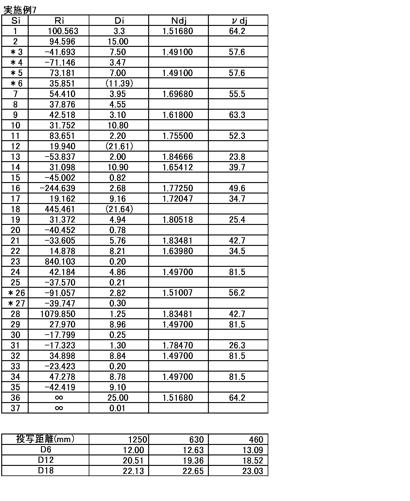
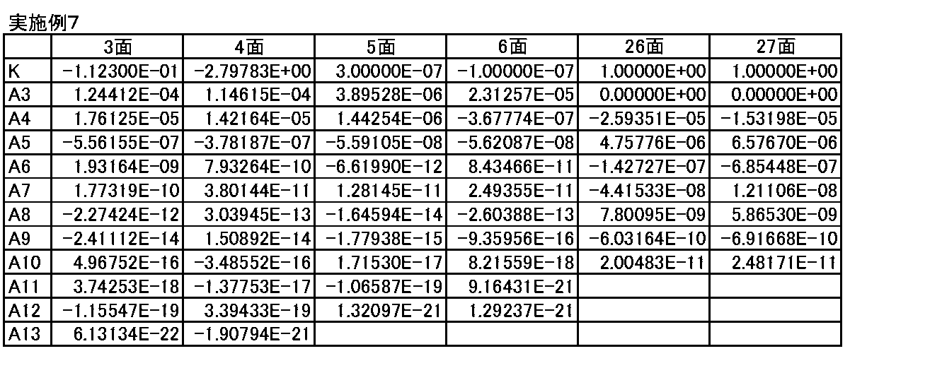
表15に上記実施例1~7の諸元、条件式(1)~(6)に関連する値および対応する値を示す。表15のFnoはFナンバー、全長は投写距離無限遠時の最も拡大側のレンズ面から縮小側の像面までの光軸上の距離(バックフォーカス分は空気換算距離)である。表15に示す各値はe線におけるものである。
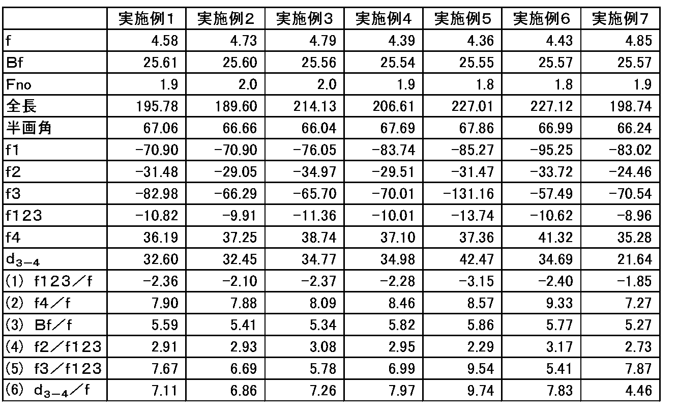
図8(A)~図8(D)にそれぞれ、実施例1の投写用広角レンズの球面収差、非点収差、ディストーション(歪曲収差)、倍率色収差(倍率の色収差)の各収差図を示す。各収差図はe線(波長546nm)に関するものであるが、球面収差図では波長460nm、波長610nmに関する収差も合わせて示している。非点収差図ではサジタル方向、タンジェンシャル方向に関する収差をそれぞれ実線、破線で示している。倍率色収差図では波長460nm、波長610nmに関する収差を示している。図8(A)の縦軸上方に記載のFno.はFナンバー、図8(B)~図8(D)の縦軸上方に記載のωは半画角を意味する。
図9(A)~図9(E)、に実施例1の投写用広角レンズのタンジェンシャル方向の各半画角における横収差図を示し、図9(F)~図9(I)に実施例1の投写用広角レンズの各半画角におけるサジタル方向の横収差図を示す。同じ半画角のタンジェンシャル方向、サジタル方向の横収差を水平方向に並べて図示しており、この2つの方向の横収差の間に記載している数値が各半画角を示す。図8(A)~図8(D)、図9(A)~図9(I)に示す収差図はいずれも投写距離無限遠時のものである。
同様に、実施例2~7の投写用広角レンズそれぞれの収差図を図10(A)~図10(D)、図11(A)~図11(I)、図12(A)~図12(D)、図13(A)~図13(I)、図14(A)~図14(D)、図15(A)~図15(I)、図16(A)~図16(D)、図17(A)~図17(I)、図18(A)~図18(D)、図19(A)~図19(I)、図20(A)~図20(D)、図21(A)~図21(I)に示す。各収差図から、実施例1~7の投写用広角レンズは各収差が良好に補正されていることがわかる。
以上、実施形態および実施例を挙げて本発明を説明したが、本発明は上記実施形態および実施例に限定されず、種々の変形が可能である。例えば、本発明の投写用広角レンズの各レンズの曲率半径、面間隔、屈折率、アッベ数、非球面係数の値は、適宜変更することが可能である。また、本発明の投写型表示装置に用いられるライトバルブや、光束分離または光束合成に用いられる光学部材は、上記構成に限定されず、種々の態様の変更が可能である。
Claims (13)
- 拡大側から順に、2枚の非球面レンズを含む第1レンズ群と、拡大側に凸面を向けた3枚の負メニスカスレンズからなる第2レンズ群と、少なくとも1つの接合レンズを含み、負の屈折力を有する第3レンズ群と、少なくとも2つの接合レンズと1枚の非球面レンズを含み、正の屈折力を有する第4レンズ群とからなり、
全系の隣り合うレンズ群の間隔のうち前記第3レンズ群と前記第4レンズ群の間隔が最長となるように構成されており、
下記条件式(1)~(3)を満たすことを特徴とする投写用広角レンズ。
-3.8<f123/f<-1.6 … (1)
6.6<f4/f<11.5 … (2)
5.1<Bf/f<6.4 … (3)
ただし、
f123:前記第1レンズ群から前記第3レンズ群までの合成焦点距離
f:全系の焦点距離
f4:前記第4レンズ群の焦点距離
Bf:縮小側のバックフォーカス(空気換算距離) - 下記条件式(1-1)を満たすことを特徴とする請求項1記載の投写用広角レンズ。
-3.2<f123/f<-1.8 … (1-1) - 下記条件式(2-1)を満たすことを特徴とする請求項1または2記載の投写用広角レンズ。
7.2<f4/f<9.4 … (2-1) - 下記条件式(3-1)を満たすことを特徴とする請求項1から3のいずれか1項記載の投写用広角レンズ。
5.2<Bf/f<5.9 … (3-1) - 下記条件式(4)を満たすことを特徴とする請求項1から4のいずれか1項記載の投写用広角レンズ。
2.0<f2/f123<3.8 … (4)
ただし、
f2:前記第2レンズ群の焦点距離 - 下記条件式(4-1)を満たすことを特徴とする請求項5記載の投写用広角レンズ。
2.2<f2/f123<3.2 … (4-1) - 下記条件式(5)を満たすことを特徴とする請求項1から6のいずれか1項記載の投写用広角レンズ。
4.8<f3/123<11.3 … (5)
ただし、
f3:前記第3レンズ群の焦点距離 - 下記条件式(5-1)を満たすことを特徴とする請求項7記載の投写用広角レンズ。
5.4<f3/123<9.6 … (5-1) - 前記第4レンズ群が、d線におけるアッベ数が80以上の材質からなる正レンズを3枚以上含むことを特徴とする請求項1から8のいずれか1項記載の投写用広角レンズ。
- 投写距離が変化したときのフォーカス調整は、前記第2レンズ群および前記第3レンズ群のみを光軸方向に移動させることにより行い、投写距離が遠方から近方に変化したときのフォーカス調整の際に、前記第2レンズ群は縮小側へ、前記第3レンズ群は拡大側へ移動するように構成されていることを特徴とする請求項1から9のいずれか1項記載の投写用広角レンズ。
- 下記条件式(6)を満たすことを特徴とする請求項1から10のいずれか1項記載の投写用広角レンズ。
4.0<d3-4/f<12.0 … (6)
ただし、
d3-4:投写距離が無限遠のときの前記第3レンズ群と前記第4レンズ群の光軸上の間隔 - 下記条件式(6-1)を満たすことを特徴とする請求項11記載の投写用広角レンズ。
4.4<d3-4/f<9.8 … (6-1) - 光源と、ライトバルブと、該光源からの光束を該ライトバルブへ導く照明光学部と、請求項1から12のいずれか1項記載の投写用広角レンズとを備え、前記光源からの光束を前記ライトバルブにより光変調し、前記投写用広角レンズによりスクリーンに投写するものであることを特徴とする投写型表示装置。
Priority Applications (3)
| Application Number | Priority Date | Filing Date | Title |
|---|---|---|---|
| CN201280022937.8A CN103562772B (zh) | 2011-05-12 | 2012-05-07 | 广角投影镜头和使用该广角投影镜头的投影显示装置 |
| JP2013513925A JP5814354B2 (ja) | 2011-05-12 | 2012-05-07 | 投写用広角レンズおよびこれを用いた投写型表示装置 |
| US14/064,961 US9201221B2 (en) | 2011-05-12 | 2013-10-28 | Wide-angle projection lens and projection display device using the same |
Applications Claiming Priority (2)
| Application Number | Priority Date | Filing Date | Title |
|---|---|---|---|
| JP2011-107114 | 2011-05-12 | ||
| JP2011107114 | 2011-05-12 |
Related Child Applications (1)
| Application Number | Title | Priority Date | Filing Date |
|---|---|---|---|
| US14/064,961 Continuation US9201221B2 (en) | 2011-05-12 | 2013-10-28 | Wide-angle projection lens and projection display device using the same |
Publications (1)
| Publication Number | Publication Date |
|---|---|
| WO2012153506A1 true WO2012153506A1 (ja) | 2012-11-15 |
Family
ID=47138994
Family Applications (1)
| Application Number | Title | Priority Date | Filing Date |
|---|---|---|---|
| PCT/JP2012/002984 Ceased WO2012153506A1 (ja) | 2011-05-12 | 2012-05-07 | 投写用広角レンズおよびこれを用いた投写型表示装置 |
Country Status (4)
| Country | Link |
|---|---|
| US (1) | US9201221B2 (ja) |
| JP (1) | JP5814354B2 (ja) |
| CN (1) | CN103562772B (ja) |
| WO (1) | WO2012153506A1 (ja) |
Cited By (2)
| Publication number | Priority date | Publication date | Assignee | Title |
|---|---|---|---|---|
| JP2015022142A (ja) * | 2013-07-19 | 2015-02-02 | 富士フイルム株式会社 | 撮像レンズおよび撮像装置 |
| JP2015114509A (ja) * | 2013-12-12 | 2015-06-22 | キヤノン株式会社 | 光学系及びそれを有する撮像装置 |
Families Citing this family (2)
| Publication number | Priority date | Publication date | Assignee | Title |
|---|---|---|---|---|
| US9939611B2 (en) * | 2014-12-10 | 2018-04-10 | Young Optics Inc. | Optical lens |
| TWI708073B (zh) * | 2019-11-05 | 2020-10-21 | 上暘光學股份有限公司 | 高解析度定焦鏡頭 |
Citations (3)
| Publication number | Priority date | Publication date | Assignee | Title |
|---|---|---|---|---|
| JP2007147970A (ja) * | 2005-11-28 | 2007-06-14 | Ricoh Opt Ind Co Ltd | 投射用レンズおよび投射型画像表示装置 |
| JP2009104048A (ja) * | 2007-10-25 | 2009-05-14 | Fujinon Corp | 投写レンズおよびこれを用いた投写型表示装置 |
| JP2010085732A (ja) * | 2008-09-30 | 2010-04-15 | Ricoh Opt Ind Co Ltd | 投射用レンズおよび投射型画像表示装置 |
Family Cites Families (9)
| Publication number | Priority date | Publication date | Assignee | Title |
|---|---|---|---|---|
| JPH09304694A (ja) * | 1995-11-07 | 1997-11-28 | Nikon Corp | 投射レンズ系及びそれを備えた投射装置 |
| JP2005316015A (ja) * | 2004-04-27 | 2005-11-10 | Nidec Copal Corp | 撮像レンズ |
| JP2005352060A (ja) * | 2004-06-09 | 2005-12-22 | Fujinon Corp | 小型の大口径広角レンズおよびこれを備えたカメラ |
| JP4855024B2 (ja) * | 2005-09-14 | 2012-01-18 | 富士フイルム株式会社 | 2群ズーム投影レンズおよび投写型表示装置 |
| JP2007256712A (ja) | 2006-03-24 | 2007-10-04 | Brother Ind Ltd | 投写用広角レンズ及びこれを備えたプロジェクタ |
| JP4864600B2 (ja) * | 2006-08-11 | 2012-02-01 | 富士フイルム株式会社 | 投写型ズームレンズおよび投写型表示装置 |
| JP2009116132A (ja) * | 2007-11-08 | 2009-05-28 | Hoya Corp | 広角レンズ系 |
| JP5118582B2 (ja) * | 2008-08-27 | 2013-01-16 | 富士フイルム株式会社 | 投影レンズおよびこれを用いた投写型表示装置 |
| JP2012189971A (ja) * | 2010-04-12 | 2012-10-04 | Fujifilm Corp | 投写用ズームレンズ、投写用変倍光学系および投写型表示装置 |
-
2012
- 2012-05-07 JP JP2013513925A patent/JP5814354B2/ja not_active Expired - Fee Related
- 2012-05-07 WO PCT/JP2012/002984 patent/WO2012153506A1/ja not_active Ceased
- 2012-05-07 CN CN201280022937.8A patent/CN103562772B/zh not_active Expired - Fee Related
-
2013
- 2013-10-28 US US14/064,961 patent/US9201221B2/en not_active Expired - Fee Related
Patent Citations (3)
| Publication number | Priority date | Publication date | Assignee | Title |
|---|---|---|---|---|
| JP2007147970A (ja) * | 2005-11-28 | 2007-06-14 | Ricoh Opt Ind Co Ltd | 投射用レンズおよび投射型画像表示装置 |
| JP2009104048A (ja) * | 2007-10-25 | 2009-05-14 | Fujinon Corp | 投写レンズおよびこれを用いた投写型表示装置 |
| JP2010085732A (ja) * | 2008-09-30 | 2010-04-15 | Ricoh Opt Ind Co Ltd | 投射用レンズおよび投射型画像表示装置 |
Cited By (2)
| Publication number | Priority date | Publication date | Assignee | Title |
|---|---|---|---|---|
| JP2015022142A (ja) * | 2013-07-19 | 2015-02-02 | 富士フイルム株式会社 | 撮像レンズおよび撮像装置 |
| JP2015114509A (ja) * | 2013-12-12 | 2015-06-22 | キヤノン株式会社 | 光学系及びそれを有する撮像装置 |
Also Published As
| Publication number | Publication date |
|---|---|
| US9201221B2 (en) | 2015-12-01 |
| JP5814354B2 (ja) | 2015-11-17 |
| US20140049835A1 (en) | 2014-02-20 |
| CN103562772A (zh) | 2014-02-05 |
| JPWO2012153506A1 (ja) | 2014-07-31 |
| CN103562772B (zh) | 2015-09-09 |
Similar Documents
| Publication | Publication Date | Title |
|---|---|---|
| JP5766798B2 (ja) | 投写用変倍光学系および投写型表示装置 | |
| CN203930190U (zh) | 投影用变焦镜头和投影型显示设备 | |
| CN203786378U (zh) | 投影用变焦透镜和投影型显示装置 | |
| CN204178035U (zh) | 投影用透镜和投影型显示装置 | |
| JP5599954B2 (ja) | 投写用ズームレンズおよび投写型表示装置 | |
| JP2008304765A (ja) | ズームレンズ及びそれを用いた画像投影装置 | |
| CN203870320U (zh) | 投影用变焦透镜和投影型显示装置 | |
| CN201666968U (zh) | 投影用变焦透镜及投影型显示装置 | |
| WO2012105181A1 (ja) | 投写レンズおよび投写型表示装置 | |
| CN204065540U (zh) | 投影用光学系统和投影型显示装置 | |
| WO2013171995A1 (ja) | 投写用変倍光学系および投写型表示装置 | |
| WO2013061536A1 (ja) | 投写用ズームレンズおよび投写型表示装置 | |
| JP5777182B2 (ja) | 投写用変倍光学系および投写型表示装置 | |
| JP2009186790A (ja) | 投写レンズおよびこれを用いた投写型表示装置 | |
| WO2012160786A1 (ja) | 投写用変倍光学系および投写型表示装置 | |
| CN206532030U (zh) | 投影用变焦透镜及投影型显示装置 | |
| CN103403604B (zh) | 投影变焦距镜头和投影显示设备 | |
| JP2013007881A (ja) | 投写用変倍光学系および投写型表示装置 | |
| JP5814354B2 (ja) | 投写用広角レンズおよびこれを用いた投写型表示装置 | |
| CN204065542U (zh) | 投影用变焦镜头和投影型显示设备 | |
| CN205608279U (zh) | 投射用变焦透镜以及投射型显示装置 | |
| JP5642903B2 (ja) | 投写用ズームレンズおよび投写型表示装置 | |
| JP2016061948A (ja) | 投写用ズームレンズおよび投写型表示装置 | |
| JP5611901B2 (ja) | 投写用変倍光学系および投写型表示装置 | |
| WO2018150981A1 (ja) | 投写用ズームレンズおよび投写型表示装置 |
Legal Events
| Date | Code | Title | Description |
|---|---|---|---|
| 121 | Ep: the epo has been informed by wipo that ep was designated in this application |
Ref document number: 12782361 Country of ref document: EP Kind code of ref document: A1 |
|
| ENP | Entry into the national phase |
Ref document number: 2013513925 Country of ref document: JP Kind code of ref document: A |
|
| NENP | Non-entry into the national phase |
Ref country code: DE |
|
| 122 | Ep: pct application non-entry in european phase |
Ref document number: 12782361 Country of ref document: EP Kind code of ref document: A1 |