WO2012147679A1 - Dispositif endoscopique et procédé de mesure - Google Patents
Dispositif endoscopique et procédé de mesure Download PDFInfo
- Publication number
- WO2012147679A1 WO2012147679A1 PCT/JP2012/060832 JP2012060832W WO2012147679A1 WO 2012147679 A1 WO2012147679 A1 WO 2012147679A1 JP 2012060832 W JP2012060832 W JP 2012060832W WO 2012147679 A1 WO2012147679 A1 WO 2012147679A1
- Authority
- WO
- WIPO (PCT)
- Prior art keywords
- pattern
- endoscope apparatus
- projection
- light
- image
- Prior art date
Links
Images


Classifications
-
- A—HUMAN NECESSITIES
- A61—MEDICAL OR VETERINARY SCIENCE; HYGIENE
- A61B—DIAGNOSIS; SURGERY; IDENTIFICATION
- A61B5/00—Measuring for diagnostic purposes; Identification of persons
- A61B5/103—Detecting, measuring or recording devices for testing the shape, pattern, colour, size or movement of the body or parts thereof, for diagnostic purposes
- A61B5/107—Measuring physical dimensions, e.g. size of the entire body or parts thereof
- A61B5/1077—Measuring of profiles
-
- A—HUMAN NECESSITIES
- A61—MEDICAL OR VETERINARY SCIENCE; HYGIENE
- A61B—DIAGNOSIS; SURGERY; IDENTIFICATION
- A61B1/00—Instruments for performing medical examinations of the interior of cavities or tubes of the body by visual or photographical inspection, e.g. endoscopes; Illuminating arrangements therefor
- A61B1/00002—Operational features of endoscopes
- A61B1/00004—Operational features of endoscopes characterised by electronic signal processing
- A61B1/00009—Operational features of endoscopes characterised by electronic signal processing of image signals during a use of endoscope
- A61B1/000095—Operational features of endoscopes characterised by electronic signal processing of image signals during a use of endoscope for image enhancement
-
- A—HUMAN NECESSITIES
- A61—MEDICAL OR VETERINARY SCIENCE; HYGIENE
- A61B—DIAGNOSIS; SURGERY; IDENTIFICATION
- A61B1/00—Instruments for performing medical examinations of the interior of cavities or tubes of the body by visual or photographical inspection, e.g. endoscopes; Illuminating arrangements therefor
- A61B1/00002—Operational features of endoscopes
- A61B1/00043—Operational features of endoscopes provided with output arrangements
- A61B1/00045—Display arrangement
-
- A—HUMAN NECESSITIES
- A61—MEDICAL OR VETERINARY SCIENCE; HYGIENE
- A61B—DIAGNOSIS; SURGERY; IDENTIFICATION
- A61B1/00—Instruments for performing medical examinations of the interior of cavities or tubes of the body by visual or photographical inspection, e.g. endoscopes; Illuminating arrangements therefor
- A61B1/00064—Constructional details of the endoscope body
- A61B1/00071—Insertion part of the endoscope body
- A61B1/0008—Insertion part of the endoscope body characterised by distal tip features
- A61B1/00096—Optical elements
-
- A—HUMAN NECESSITIES
- A61—MEDICAL OR VETERINARY SCIENCE; HYGIENE
- A61B—DIAGNOSIS; SURGERY; IDENTIFICATION
- A61B1/00—Instruments for performing medical examinations of the interior of cavities or tubes of the body by visual or photographical inspection, e.g. endoscopes; Illuminating arrangements therefor
- A61B1/00163—Optical arrangements
- A61B1/00174—Optical arrangements characterised by the viewing angles
- A61B1/00179—Optical arrangements characterised by the viewing angles for off-axis viewing
-
- A—HUMAN NECESSITIES
- A61—MEDICAL OR VETERINARY SCIENCE; HYGIENE
- A61B—DIAGNOSIS; SURGERY; IDENTIFICATION
- A61B1/00—Instruments for performing medical examinations of the interior of cavities or tubes of the body by visual or photographical inspection, e.g. endoscopes; Illuminating arrangements therefor
- A61B1/00163—Optical arrangements
- A61B1/00193—Optical arrangements adapted for stereoscopic vision
-
- A—HUMAN NECESSITIES
- A61—MEDICAL OR VETERINARY SCIENCE; HYGIENE
- A61B—DIAGNOSIS; SURGERY; IDENTIFICATION
- A61B1/00—Instruments for performing medical examinations of the interior of cavities or tubes of the body by visual or photographical inspection, e.g. endoscopes; Illuminating arrangements therefor
- A61B1/00163—Optical arrangements
- A61B1/00194—Optical arrangements adapted for three-dimensional imaging
-
- A—HUMAN NECESSITIES
- A61—MEDICAL OR VETERINARY SCIENCE; HYGIENE
- A61B—DIAGNOSIS; SURGERY; IDENTIFICATION
- A61B1/00—Instruments for performing medical examinations of the interior of cavities or tubes of the body by visual or photographical inspection, e.g. endoscopes; Illuminating arrangements therefor
- A61B1/04—Instruments for performing medical examinations of the interior of cavities or tubes of the body by visual or photographical inspection, e.g. endoscopes; Illuminating arrangements therefor combined with photographic or television appliances
- A61B1/05—Instruments for performing medical examinations of the interior of cavities or tubes of the body by visual or photographical inspection, e.g. endoscopes; Illuminating arrangements therefor combined with photographic or television appliances characterised by the image sensor, e.g. camera, being in the distal end portion
-
- A—HUMAN NECESSITIES
- A61—MEDICAL OR VETERINARY SCIENCE; HYGIENE
- A61B—DIAGNOSIS; SURGERY; IDENTIFICATION
- A61B1/00—Instruments for performing medical examinations of the interior of cavities or tubes of the body by visual or photographical inspection, e.g. endoscopes; Illuminating arrangements therefor
- A61B1/06—Instruments for performing medical examinations of the interior of cavities or tubes of the body by visual or photographical inspection, e.g. endoscopes; Illuminating arrangements therefor with illuminating arrangements
- A61B1/0605—Instruments for performing medical examinations of the interior of cavities or tubes of the body by visual or photographical inspection, e.g. endoscopes; Illuminating arrangements therefor with illuminating arrangements for spatially modulated illumination
-
- A—HUMAN NECESSITIES
- A61—MEDICAL OR VETERINARY SCIENCE; HYGIENE
- A61B—DIAGNOSIS; SURGERY; IDENTIFICATION
- A61B1/00—Instruments for performing medical examinations of the interior of cavities or tubes of the body by visual or photographical inspection, e.g. endoscopes; Illuminating arrangements therefor
- A61B1/06—Instruments for performing medical examinations of the interior of cavities or tubes of the body by visual or photographical inspection, e.g. endoscopes; Illuminating arrangements therefor with illuminating arrangements
- A61B1/0661—Endoscope light sources
- A61B1/0676—Endoscope light sources at distal tip of an endoscope
-
- A—HUMAN NECESSITIES
- A61—MEDICAL OR VETERINARY SCIENCE; HYGIENE
- A61B—DIAGNOSIS; SURGERY; IDENTIFICATION
- A61B5/00—Measuring for diagnostic purposes; Identification of persons
- A61B5/0059—Measuring for diagnostic purposes; Identification of persons using light, e.g. diagnosis by transillumination, diascopy, fluorescence
- A61B5/0082—Measuring for diagnostic purposes; Identification of persons using light, e.g. diagnosis by transillumination, diascopy, fluorescence adapted for particular medical purposes
- A61B5/0084—Measuring for diagnostic purposes; Identification of persons using light, e.g. diagnosis by transillumination, diascopy, fluorescence adapted for particular medical purposes for introduction into the body, e.g. by catheters
-
- A—HUMAN NECESSITIES
- A61—MEDICAL OR VETERINARY SCIENCE; HYGIENE
- A61B—DIAGNOSIS; SURGERY; IDENTIFICATION
- A61B5/00—Measuring for diagnostic purposes; Identification of persons
- A61B5/103—Detecting, measuring or recording devices for testing the shape, pattern, colour, size or movement of the body or parts thereof, for diagnostic purposes
- A61B5/107—Measuring physical dimensions, e.g. size of the entire body or parts thereof
- A61B5/1076—Measuring physical dimensions, e.g. size of the entire body or parts thereof for measuring dimensions inside body cavities, e.g. using catheters
-
- G—PHYSICS
- G02—OPTICS
- G02B—OPTICAL ELEMENTS, SYSTEMS OR APPARATUS
- G02B23/00—Telescopes, e.g. binoculars; Periscopes; Instruments for viewing the inside of hollow bodies; Viewfinders; Optical aiming or sighting devices
- G02B23/24—Instruments or systems for viewing the inside of hollow bodies, e.g. fibrescopes
- G02B23/2407—Optical details
- G02B23/2423—Optical details of the distal end
-
- G—PHYSICS
- G02—OPTICS
- G02B—OPTICAL ELEMENTS, SYSTEMS OR APPARATUS
- G02B23/00—Telescopes, e.g. binoculars; Periscopes; Instruments for viewing the inside of hollow bodies; Viewfinders; Optical aiming or sighting devices
- G02B23/24—Instruments or systems for viewing the inside of hollow bodies, e.g. fibrescopes
- G02B23/2407—Optical details
- G02B23/2461—Illumination
- G02B23/2469—Illumination using optical fibres
-
- G—PHYSICS
- G06—COMPUTING; CALCULATING OR COUNTING
- G06T—IMAGE DATA PROCESSING OR GENERATION, IN GENERAL
- G06T7/00—Image analysis
- G06T7/50—Depth or shape recovery
- G06T7/521—Depth or shape recovery from laser ranging, e.g. using interferometry; from the projection of structured light
-
- H—ELECTRICITY
- H04—ELECTRIC COMMUNICATION TECHNIQUE
- H04N—PICTORIAL COMMUNICATION, e.g. TELEVISION
- H04N23/00—Cameras or camera modules comprising electronic image sensors; Control thereof
- H04N23/56—Cameras or camera modules comprising electronic image sensors; Control thereof provided with illuminating means
-
- H—ELECTRICITY
- H04—ELECTRIC COMMUNICATION TECHNIQUE
- H04N—PICTORIAL COMMUNICATION, e.g. TELEVISION
- H04N23/00—Cameras or camera modules comprising electronic image sensors; Control thereof
- H04N23/50—Constructional details
- H04N23/555—Constructional details for picking-up images in sites, inaccessible due to their dimensions or hazardous conditions, e.g. endoscopes or borescopes
Definitions
- the present invention relates to an endoscope apparatus and a measuring method, and more specifically, an endoscope apparatus that measures a three-dimensional shape of a surface of a test object by projecting a pattern such as a stripe on the test object, and a streak on the test object.
- the present invention relates to a method for measuring the three-dimensional shape of the surface of a test object by projecting a pattern such as the above.
- an endoscope (endoscope device) having a long insertion portion and having observation means such as an optical system and an image sensor at the tip of the insertion portion is used.
- observation means such as an optical system and an image sensor at the tip of the insertion portion
- a plurality of fringe images obtained by projecting fringes on the test object are obtained while shifting the phase of the fringes, and a known phase shift method using the plurality of fringe images is used.
- a known phase shift method using the plurality of fringe images is used. What calculates the three-dimensional shape of a test object is known.
- Patent Document 1 describes an endoscope apparatus in which two projection windows for projecting stripes are provided on the distal end surface of an insertion portion.
- An object of the present invention is to provide an endoscope apparatus in which an insertion portion is reduced in diameter. It is another object of the present invention to provide a measurement method that can accurately measure a three-dimensional shape even in an endoscope apparatus in which an insertion portion has a reduced diameter. Furthermore, it aims at providing the measuring method which measures a three-dimensional shape in a short time using an endoscope apparatus.
- the endoscope apparatus is an endoscope apparatus that performs measurement of the test object using a pattern projection image of the test object on which a light brightness / darkness pattern is projected.
- An endoscope apparatus includes an insertion unit, an imaging unit, an illumination unit, and a pattern projection unit.
- the imaging unit is provided at a distal end of the insertion unit and acquires an image of the test object.
- the illumination unit emits illumination light that illuminates the observation field of view of the imaging unit.
- the pattern projection unit projects the light and dark pattern onto the test object.
- An objective optical system that forms an image of the test object on the imaging unit, one or more illumination windows that emit the illumination light, and the test object from the pattern projection unit are provided on the distal end surface of the insertion unit.
- a projection window for projecting the light and dark pattern onto an object.
- the objective optical system has an optical axis on the emission side from the objective optical system to the imaging unit among the optical axes of the objective optical system, the center of the insertion unit. It arrange
- the objective optical system is a direct-view objective optical system in which both the incident-side optical axis and the outgoing-side optical axis are parallel to the central axis. Furthermore, the objective optical system is provided on a distal end surface of the distal end portion of the insertion portion, and is disposed at a position decentered with respect to the central axis.
- the projection window is provided on the distal end surface, and is disposed at a position eccentric with respect to the central axis of the insertion portion.
- the objective optical system is exposed on the outer peripheral surface of the distal end portion of the insertion portion, and the optical axis on the incident side is arranged at a position twisted with respect to the central axis.
- This is a side view type objective optical system.
- the projection window is exposed on the outer peripheral surface of the distal end portion of the insertion portion, and the projection window is viewed from the thickness direction of the projection window.
- a center line that passes through the center of the projection window and extends in the thickness direction of the projection window is disposed at a twisted position with respect to the center axis of the insertion portion.
- the objective optical system is exposed on the outer peripheral surface of the distal end portion of the insertion portion, and the optical axis on the incident side intersects the central axis of the insertion portion.
- This is a side-viewing objective optical system.
- the projection window has a plane in which the center of the projection window when the projection window is viewed from the thickness direction of the projection window is defined by the central axis of the insertion portion and the optical axis on the incident side.
- the insertion portion is disposed on the outer peripheral surface of the distal end portion.
- the pattern projection unit has one or more line-shaped parallel patterns.
- the pattern projection unit includes a projection light source, a pattern generation unit that changes the intensity distribution of the light emitted from the projection light source, and generates the light-dark pattern. Is provided.
- the endoscope apparatus includes an optical fiber that guides light emitted from the projection light source to the pattern generation unit. Further, the projection light source is provided on a proximal end side of the insertion portion, and the pattern generation portion is provided on a distal end portion of the insertion portion.
- the projection light source and the pattern generation unit are provided at a distal end of the insertion unit.
- the endoscope apparatus includes an optical fiber that is emitted from the projection light source and guides the light / dark pattern generated by the pattern generation unit to a distal end side of the insertion unit. Prepare. Further, the projection light source and the pattern generation unit are provided on the proximal end side of the insertion unit.
- the endoscope apparatus includes an optical adapter that can be detachably attached to a distal end portion of the insertion portion, and the pattern generation portion is provided in the optical adapter. .
- the projection light source is provided in the optical adapter.
- the endoscope apparatus includes switching means for switching between the light for projecting the bright and dark pattern and the illumination light.
- the measurement method according to the sixteenth aspect of the present invention is a measurement method for measuring the three-dimensional shape of a test object using an endoscope (endoscope device).
- a predetermined light / dark pattern is projected onto the test object from one place of the endoscope, and a portion of the test object on which the light / dark pattern is projected is imaged. Then, at least one pattern projection image is acquired, and the three-dimensional shape of the portion on which the light and dark pattern is projected is measured using the pattern projection image.
- the measurement method according to the seventeenth aspect of the present invention is a measurement method for measuring a three-dimensional shape of a test object using an endoscope apparatus.
- a predetermined fringe pattern is projected onto the test object from one location of the endoscope apparatus, and a portion of the test object on which the fringe pattern is projected is projected.
- An image is captured to obtain a single fringe image, and the three-dimensional shape of the portion onto which the fringe pattern is projected is measured from the single fringe image using a spatial phase shift method or a Fourier transform method.
- a measuring method comprising: obtaining a bright field image of a portion onto which the fringe pattern is projected at least before or after obtaining the one fringe image.
- the measurement method acquires at least one bright field image before and after acquiring the one striped image.
- At least two images selected for detecting that the position of the endoscope device has shifted are selected from the bright field images. Is done.
- the diameter of the insertion portion can be reduced.
- the measurement method according to the aspect of the present invention it is possible to accurately measure a three-dimensional shape even in an endoscope apparatus in which the insertion portion has a reduced diameter.
- the three-dimensional shape can be measured by analyzing one striped image photographed using the endoscope apparatus.
- the three-dimensional shape can be measured in a short time using the endoscope apparatus.
- FIG. 1 is a block diagram illustrating a configuration of an endoscope apparatus 1 according to the present embodiment.
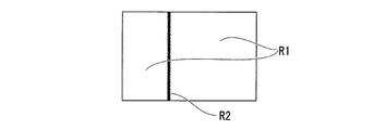
- FIG. 2 is a schematic diagram showing a light / dark pattern projected by the endoscope apparatus 1.
- the endoscope apparatus 1 is used for internal observation of a test object, observation of a test object at a position where a normal observation apparatus is difficult to access, and the like.
- the endoscope apparatus 1 includes a long insertion portion 10 and a main body portion 20 to which a proximal end of the insertion portion 10 is connected.
- the insertion part 10 is formed in a tubular shape, and is inserted into the inside of the test object or an access path to the test object.
- the insertion unit 10 includes an imaging unit 30 that acquires an image of the test object, an illumination unit 40 that illuminates the observation field of view in front of the insertion unit 10, and a pattern projection unit 50 that projects a light / dark pattern onto the test object. It has been.
- the pattern projection unit 50 projects a fringe pattern onto the test object as a bright and dark pattern.
- the distal end surface 10a of the insertion unit 10 is provided with an opening 11 for allowing external light to enter the objective optical system 32 of the imaging unit 30, and illumination for irradiating illumination light from the illumination unit 40 forward of the insertion unit.
- a window 12 and a projection window 13 for irradiating the stripes from the pattern projection unit 50 in front of the insertion unit are provided.
- the imaging unit 30 includes an imager 31 disposed near the distal end of the insertion unit 10, an objective optical system 32 disposed in front of the imager 31, and an imager control unit 33 connected to the imager 31. .
- various known configurations including various image sensors such as a CCD and a CMOS can be appropriately selected and used.
- the objective optical system 32 is disposed in the opening 11 of the insertion portion 10. Reflected light within an observation field having a predetermined field angle and defined by the field angle is incident on the imager 31 to form an image of the test object.
- the objective optical system 32 includes a light transmissive cover member 32 a that seals the opening 11.
- the imager control unit 33 is provided in the main body unit 20 and is connected to the imager 31 by a wiring 34 extending in the insertion unit 10.
- the imager control unit 33 performs various controls such as driving of the imager 31 and setting for acquiring a video signal.
- the illumination unit 40 includes a first light source 41, an illumination optical system 42, a first fiber bundle 43 that guides light from the first light source 41 to the illumination optical system 42, and between the first light source 41 and the first fiber bundle 43. And a first incident optical system 44.
- the first light source 41 is a general white light source and is disposed inside the main body 20.
- a light emitting element such as an LED or a laser, a halogen lamp, or the like can be employed.
- the illumination optical system 42 is attached at or near the distal end of the insertion portion 10.
- the illumination optical system 42 includes a light transmissive cover member 42 a provided in the illumination window 12 of the insertion unit 10 and a lens group (not shown).
- the illumination optical system 42 spreads the light emitted from the first light source 41 in the field of view suitable for the angle of view of the objective optical system 32 and emits it from the illumination window 12 to illuminate the entire observation field.
- the first fiber bundle 43 extends from the vicinity of the illumination optical system 42 to the vicinity of the first light source 41 in the main body 20 through the insertion portion 10.
- a general light guide can be used.
- the first incident optical system 44 converges the light emitted from the first light source 41 to the same extent as the diameter of the first fiber bundle 43 and efficiently introduces it into the first fiber bundle 43.
- the pattern projection unit 50 includes a second light source 51 (projection light source), a projection optical system 52, a second fiber bundle 53 that guides light from the second light source 51 to the projection optical system 52, a second light source 51, and a second light source 51.
- a second incident optical system 54 disposed between the fiber bundle 53 and a pattern generation unit 55 disposed on the optical path of the light emitted from the second light source 51 is provided.
- the second light source 51 is a white light source similar to the first light source 41 and is disposed inside the main body 20.
- the second light source 51 may be a light source that emits light having a wavelength different from that of the first light source 41.
- the projection optical system 52 is attached at or near the distal end of the insertion portion 10.
- the projection optical system 52 includes a light transmissive cover member 52 a provided in the projection window 13 of the insertion unit 10. Note that the cover member 52a provided in the projection window 13 may have a lens shape.
- the projection optical system 52 projects the light emitted from the second light source 51 into a field of view suitable for the angle of view of the objective optical system 32 and projects it from one projection window 13 into the observation field.
- the second fiber bundle 53 extends from the vicinity of the projection optical system 52 through the insertion section 10 to the vicinity of the second light source 51 in the main body section 20.
- a general light guide can be used similarly to the first fiber bundle 43.
- the second incident optical system 54 converges the light emitted from the second light source 51 to the same extent as the diameter of the second fiber bundle 53 and efficiently introduces it into the second fiber bundle 53.
- the pattern generation unit 55 can use a known configuration that can form a plurality of fringe patterns out of phase. For example, a configuration in which a slit plate having a plurality of slits is moved by an actuator, or a transparent plate made of glass, resin, or the like on which a plurality of fringe patterns whose phases are shifted from each other is moved by an actuator is used.
- a liquid crystal shutter module that can switch between transmission and non-transmission of light for each element
- a MEMS (microelectronic device system) mirror module that includes a fine reflection mirror for each element, and the like may be used as the pattern generation unit 55.
- the pattern generation unit 55 Good.
- the control is performed for each element, a plurality of fringe patterns whose phases are shifted can be formed without moving the entire pattern generation unit 55. Therefore, there is an advantage that the configuration of the pattern projection unit 50 can be simplified.
- the fringe pattern is switched by the pattern control unit 56 connected to the pattern generation unit 55.
- the shape of the light / dark pattern is not limited to the stripe pattern, and may be a plurality of line-like parallel lines as shown in FIG.
- a single line (described later) as shown in FIG. 9 may be used. Further, it may be a plurality of points, a lattice pattern in which a plurality of vertical lines and horizontal lines intersect, or a concentric pattern.
- the 1st light source 41 and the 2nd light source 51 are connected to the light source control part 21 which controls on / off of these light sources.
- the imager control unit 33, the pattern control unit 56, and the light source control unit 21 are connected to a main control unit 22 that controls the entire endoscope apparatus 1.
- the main control unit 22 is connected to an operation unit 23 for a user to make various inputs to the endoscope apparatus 1.
- the main control unit 22 is connected to a main storage device (RAM 24).
- an auxiliary storage device 25 such as a storage device having a rewritable nonvolatile memory or a magnetic storage device is electrically connected to the main control unit 22.
- a ROM 26 (or EPROM, EEPROM, or the like) that records firmware or the like may be connected to the main control unit 22 as necessary.
- the video processor 27 that processes the video signal acquired by the imager 31 is connected to the imager control unit 33 and the main control unit 22.
- a monitor 28 that displays a video signal processed by the video processor 27 as an image is connected to the video processor 27.
- the measurement method according to the first embodiment of the present invention is a measurement method for measuring the three-dimensional shape of a test object using the endoscope apparatus 1.
- the endoscope apparatus 1 When using the endoscope apparatus 1, first, the user inserts the insertion portion 10 into the inside of the test object or an access path to the test object such as a duct, and the like, until the predetermined observation site is reached. Advance the tip. The user switches the observation mode for observing a desired part of the test object and the measurement mode for measuring the three-dimensional shape of the test part, as necessary, to inspect the test object.
- the light source control unit 21 controls the first light source 41 to be turned on and the second light source 51 to be turned off.
- the fringe pattern is not projected from the pattern projection unit 50, and the observation field is illuminated with white light from the illumination unit 40, and the observation field is illuminated (hereinafter, this illumination state is referred to as “observation state”).
- the illuminated image of the object is formed on the imager 31 through the objective optical system 32.
- the video signal sent from the imager 31 is processed by the video processor 27 and displayed on the monitor 28. The user can observe the test object from the image of the test object displayed on the monitor 28, and can store the image as necessary.
- the user When switching from the observation mode to the measurement mode, the user inputs an instruction to switch the mode.
- a known input device can be adopted as an input device for inputting an instruction for switching modes.
- a configuration in which a switch is provided in the operation unit 23 or a configuration in which the monitor 28 is changed to a touch panel to be a software switch can be employed.
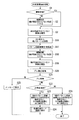
- the measurement image photographing process (see FIG. 3) is started in the main control unit 22.
- step S1 it is determined whether or not the endoscope apparatus 1 is in an observation state (step S1 shown in FIG. 3). If it is determined in step S1 that it is in the observation state, the process proceeds to step S3, and if it is in a state other than the observation state (for example, a measurement state described later) in step S1, the process proceeds to step S2. This ends step S1.
- Step S2 is a step of switching the endoscope apparatus 1 to the observation state.
- the first light source 41 is on-controlled and the second light source 51 is off-controlled.
- the pattern projection unit 50 does not project the fringe pattern, and the illumination unit 40 irradiates the observation field with white light, and the observation field is illuminated.
- Step S2 is complete
- Step S ⁇ b> 3 is a step of capturing an image of the test object that is not projected with the fringe pattern and is illuminated with white light from the illumination unit 40.
- step S ⁇ b> 3 an image is acquired by the imager 31 of the imaging unit 30 in a state where the test object is illuminated with white light from the illumination unit 40 (hereinafter, an image captured in the observation state is referred to as a “bright field image”). Called).
- the bright field image photographed in step S3 is temporarily stored in the RAM 24.
- Step S3 is complete
- Step S4 is a branching step for capturing a desired number of pattern projection images.
- the predetermined number N of pattern projection images to be captured is compared with the number of pattern projection images currently stored in the RAM 24, and the number of pattern projection images stored in the RAM 24 is less than the number N of planned projection images. If so, the process proceeds to step S5. On the other hand, if the number of pattern projection images stored in the RAM 24 is the scheduled number N, the process proceeds to step S7. This ends step S4.
- Step S5 is a step of projecting the fringe pattern onto the test object.
- the first light source 41 is turned off and the second light source 51 is turned on based on a command from the main control unit 22.
- the white light irradiated from the illumination unit 40 is turned off, and the fringe pattern is projected from the pattern projection unit 50 onto the test object.
- the fringe pattern projected on the test object is a pattern in which bright portions R ⁇ b> 1 due to a white light source and dark portions R ⁇ b> 2 shielded by the pattern generation unit 55 are alternately arranged.
- the pattern generation unit 55 operates the actuator to set the phase of the fringe pattern to an appropriate phase.
- a state in which appropriate stripes are projected onto the test object from one place hereinafter, this state is referred to as a “pattern projection state”.
- Step S5 is complete
- Step S6 is a step of capturing a pattern projection image in the pattern projection state.
- the fringe pattern projected onto the test object is a pattern that changes according to the three-dimensional shape of the test object.
- an image is acquired by the imager 31 of the imaging unit 30 (hereinafter, an image photographed in a pattern projection state is referred to as a “pattern projection image”).
- the pattern projection image photographed in step S6 is temporarily stored in the RAM 24. This ends step S6 and returns to step S4.
- Steps S4 to S6 are repeated until the number of pattern projection images to be shot reaches the planned number of shots N.
- the phase of the fringe pattern is changed as appropriate, and, for example, a total of N images of the test object on which the fringes with different phases are projected are taken one by one.
- Step S7 is a step of switching the endoscope apparatus 1 to the observation state.
- the first light source 41 is on-controlled and the second light source 51 is off-controlled.
- the pattern projection unit 50 does not project the fringe pattern, and the illumination unit 40 irradiates the observation field with white light, and the observation field is illuminated.
- Step S7 is complete
- Step S ⁇ b> 8 is a step of capturing an image of the test object illuminated with white light from the illuminating unit 40 without a stripe pattern being projected.
- step S ⁇ b> 8 a bright field image is captured by the imager 31 of the imaging unit 30 in a state where the test object is illuminated with white light from the illumination unit 40.
- the bright field image photographed in step S8 is temporarily stored in the RAM 24.
- Step S8 is complete
- step S9 based on the images (bright field image and pattern projection image) photographed between step S3 and step S8, the relative movement between the insertion unit 10 and the subject between step S3 and step S8 ( (Hereinafter referred to as “blur”).
- step S9 first, two images are selected from at least one of the bright field image and the stripe image stored in the RAM 24. For example, in the first embodiment, a bright-field image captured before capturing N pattern projection images and a bright-field image captured after capturing N pattern projection images are selected. Subsequently, the same feature point is detected from the two selected images, and the coordinates of the feature point in the two images are calculated. Step S9 is completed now and it progresses to Step S10.
- Step S10 is a step of branching the process by determining blurring of the two images using the feature points detected in step S9.
- step S10 if the coordinates of the feature points in the two images are the same in each image, it is determined that there is no blur between the first image and the subsequent image, and the process proceeds to step S11. On the other hand, if the coordinates of the feature points in the two images are different in each image, it is determined that there is a blur between the first image and the subsequent image, and a blur has occurred. Is displayed on the monitor 28 (step S14), and the series of processes is terminated. This ends step S10.
- Step S11 is a step in which the user selects whether to perform three-dimensional measurement using the captured pattern projection image now or later.
- step S11 for example, an inquiry such as “Perform measurement?” Is displayed on the monitor 28, and the user is prompted to input whether to perform three-dimensional measurement using the captured pattern projection image. If there is an input that the measurement can be performed, the process proceeds to step S12. If there is an input that the measurement is not performed, the process proceeds to step S15. This ends step S11.
- Step S12 is a step of performing analysis for performing three-dimensional measurement.
- the three-dimensional shape is analyzed based on the pattern projection image stored in the RAM 24.
- the three-dimensional shape of the test object is analyzed by, for example, a known temporal phase shift method using N pattern projection images having different phases.
- the analysis result of the three-dimensional shape is generated as a text file or a binary file, and is stored in the auxiliary storage device 25 together with N pattern projection images.
- step S12 may be performed as the background process of step S11 simultaneously with the start of step S11. Step S12 is completed now and it progresses to Step S13.
- step S13 the display on the monitor 28 is shifted to the screen of various measurement modes, and the measurement result is displayed on the monitor 28 using the information stored in step S12.
- step S13 the result of analysis in step S12 is overlaid on the bright field image acquired in step S3 (or the bright field image acquired in step S8).
- the three-dimensional shape is displayed on the monitor 28. Thereby, the user can know the three-dimensional shape of the test object.
- Step S13 is complete
- Step S15 is a step branched from step S11 described above, and is a step for performing information processing necessary for displaying the measurement result later.
- step S15 as in step S12, the three-dimensional shape is analyzed based on the pattern projection image stored in the RAM 24.
- the three-dimensional shape of the test object is analyzed by the temporal phase shift method using N pattern projection images having different phases.
- the bright field image, the pattern projection image, the analysis result of the three-dimensional shape, and the optical parameters used for the analysis are stored in the auxiliary storage device 25 as a binary file or a text file, respectively.
- Step S15 is complete
- the projection window 13 of the pattern projection unit 50 is provided at one place on the distal end surface 10a of the insertion unit 10, it is inserted. Compared with the case where two projection windows 13 are provided on the distal end surface 10a of the portion 10, the insertion portion 10 can be made thinner.
- the projection windows 13 for projecting the stripe pattern are provided at a plurality of positions as in the conventional case, the area occupied by the projection window 13 on the distal end surface 10a of the insertion portion 10 of the endoscope apparatus 1 is large, and the illumination window 12 It is difficult to increase the occupation area of the objective optical system 32. For example, if the area occupied by the illumination window 12 is small, the amount of illumination light may be insufficient. Further, if the area occupied by the objective optical system 32 is small, it is difficult to increase the diameter of the lens, and the image may become dark.
- the endoscope apparatus 1 since the projection window 13 that projects the fringe pattern is one, the occupation area of the illumination window 12 and the objective optical system 32 is increased. Can do. As a result, a brighter image can be acquired even with the insertion section 10 having a thickness equivalent to that of a conventional endoscope. In addition, even the insertion unit 10 having a diameter smaller than that of a conventional endoscope can acquire an image with brightness equal to or higher than that of the conventional endoscope.
- the measurement method of the first embodiment of the present invention even in an environment in which a fringe pattern is projected from one projection window 13 in the endoscope apparatus 1 in which the insertion portion 10 is reduced in diameter, it is accurate. A three-dimensional shape can be measured.
- blur is detected using bright field images before and after pattern projection images are taken, and when it is determined that there is no blur, a three-dimensional shape is analyzed.
- the analysis is not performed while the fringe patterns on the plurality of pattern projection images are shifted. For this reason, the analysis precision of a three-dimensional shape can be improved. Further, it is possible to suppress a positional deviation when the measurement result using the pattern projection image is displayed as an overlay on the bright field image.
- Modification 1 of the first embodiment a modification of the endoscope apparatus 1 and the measurement method described in the first embodiment will be described.
- This modification is different from the above-described first embodiment in that a pattern generating unit 55A (see FIG. 1) is provided instead of the pattern generating unit 55.
- the pattern generation unit 55A cannot project light and dark patterns having different phases.
- the pattern generation unit 55A is configured to be able to project a light / dark pattern having a specific phase onto the test object. That is, the pattern generation unit 55A of the present modification is configured in a small size without an actuator that moves a slit plate or the like.
- the method for measuring the three-dimensional shape of the test object is also different.
- the measurement method of the present modification will be described focusing on the point of difference in processing content from the first embodiment described above.
- the scheduled number of shots N in step S4 is 1, and one pattern projection image is shot without repeating steps S4 to S6 in the above-described embodiment, and the process proceeds to step S7.
- step S12 and step S15 a three-dimensional shape is analyzed by a spatial phase shift method or a Fourier transform method using one pattern projection image.
- the measurement method of this modification is a method that can be similarly applied even if the pattern generation unit 55 includes an actuator that moves a slit plate or the like, and a temporal phase shift method using a plurality of pattern projection images. 3D shape can be analyzed quickly compared to.
- a pattern generation unit 55A (see FIG. 1) is provided, and the pattern projection unit 50 projects a single pattern of bright or dark lines as shown in FIG. 9 onto the test object. It is configured to be able to.
- FIG. 9 shows a case where one streak (straight line) dark part R2 is projected in the bright part R1. Note that one streaky bright portion R1 may be projected in the dark portion R2.
- the one pattern itself projected from the pattern projection unit 50 does not move or change its shape or direction. That is, the pattern generation unit 55A of the present modification is configured in a small size without an actuator that moves a slit plate or the like.
- the measurement method of the three-dimensional shape of the test object is also different.
- the measurement method of the present modification will be described focusing on the point of difference in processing content from the first embodiment of the above-described modification 1.
- step S12 and step S15 a three-dimensional shape is analyzed by a light cutting method using one pattern projection image.
- a three-dimensional shape is analyzed on a single pattern using a single pattern projection image. Therefore, compared to the case of analyzing the entire surface of a single pattern projection image in the first embodiment described above, although the portion where the three-dimensional shape can be measured is limited, the analysis time can be greatly shortened. it can.
- the measurement method of this modification is a method that can be similarly applied even if the pattern generation unit 55 includes an actuator that moves a slit plate or the like.
- the second light source 51 is not provided, but switching means for causing the light emitted from the first light source 41 to enter the second fiber bundle 53 is provided.
- the switching means for example, a device that switches the optical path of the light emitted from the first light source 41 in a plurality of directions, such as a MEMS mirror module, can be employed. Even with such a configuration, the same effects as those of the endoscope apparatus 1 described in the first embodiment described above can be obtained. In addition, since a single light source can be used, the number of parts of the endoscope apparatus 1 can be reduced.
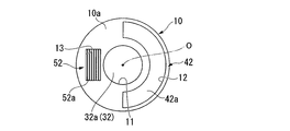
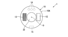
- FIGS. 4 to 6 are diagrams showing the configuration of the direct-view insertion section 10 that includes the illumination window 12, the projection window 13, and the like on the distal end surface 10a. As shown in FIGS. 4 to 6, there are various modes of arrangement of the components on the distal end surface 10 a of the insertion portion 10 of the endoscope apparatus 1.
- the objective optical system 32 is arranged on the central axis O of the insertion portion 10.
- the illumination window 12 is provided so as to surround the objective optical system 32 by a half circumference of the outer periphery of the objective optical system 32.
- the projection window 13 is disposed on the opposite side of the illumination window 12 with respect to the objective optical system 32. In such an arrangement, the area occupied by the illumination window 12 can be increased.
- the shape of the objective optical system 32 is generally a circle or a shape close to a circle.
- the illumination window 12 and the projection window 13 can be efficiently arranged at the distal end portion of the endoscope whose arrangement area is limited, and the distal end portion of the endoscope. It is easy to reduce the diameter. Furthermore, since the center of the endoscopic image coincides with the central axis O of the insertion unit 10, the operator can insert the endoscope without feeling uncomfortable while observing the image of the subject on the monitor.
- a pattern generation unit 55 is provided on the back side of the projection window 13.
- the pattern generation unit 55 is arranged such that a line pattern is positioned in a direction perpendicular to the arrangement direction of the projection window 13 and the objective optical system.
- a perpendicular distance from the center point of the objective optical system to the line pattern (hereinafter referred to as a base line length) is ensured as long as possible, and the arrangement relationship in which the arrangement interval between the projection window and the objective optical system is closest is established. It is composed. Since the measurement accuracy is improved as the baseline length is longer, according to the present modification, a three-dimensional shape can be measured with high accuracy even in an endoscope apparatus in which the insertion portion has a reduced diameter.
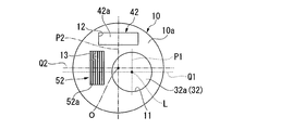
- the objective optical system 32 is arranged at a position decentered with respect to the central axis O of the insertion portion 10. As shown in FIG. 5, it is also possible to arrange the illumination windows 12 at two locations sandwiching the objective optical system 32 and the projection window 13 therebetween.
- the objective optical system 32 is arranged so that the optical axis on the emission side of reflected light in the observation field from the objective optical system 32 toward the imager 31 is parallel to the central axis O and decentered.
- the opening 11, the illumination window 12, and the projection window 13 in which the objective optical system 32 is disposed are decentered with respect to the central axis O of the insertion unit 10 on the distal end surface 10 a of the insertion unit 10. It may be arranged at the position. Further, the vertical axis P1 and the left and right axis Q1 passing through the optical axis L of the objective optical system 32 may be disposed at a position where the vertical axis P2 and the left and right axis Q2 passing through the central axis of the insertion portion 10 do not overlap.
- the objective optical system 32 is on the central axis O of the insertion unit 10.
- the insertion portion 10 can be further reduced in diameter.
- the first fiber bundle 43 is not provided, the light from the first light source 41 is directly irradiated toward the illumination window 12, the second fiber bundle 53 is not provided, and the first The light from the two light sources 51 is directly irradiated toward the stripe pattern generation unit 55.
- the first light source 41, the second light source 51, and the imager 31 are provided in the vicinity of the distal end of the insertion portion 10, and the removable optical adapter 10 ⁇ / b> A is provided at the distal end portion of the insertion portion 10. It can also be.
- the optical adapter 10A accommodates the illumination window 12, the projection window 13, and a part of the objective optical system 32. Further, the distal end surface 10a1 of the optical adapter 10A corresponds to the distal end surface 10a of the insertion portion 10 in the first embodiment described above.
- the first light source 41 and the illumination window 12 are connected by an optical fiber 43A arranged in the optical adapter 10A.
- the second light source 51 and the pattern generation unit 55 are connected by an optical fiber 53A arranged in the optical adapter 10A.
- the first light source 41 and the second light source 51 are provided in the vicinity of the distal end of the insertion portion 10, when the insertion portion 10 has a length exceeding, for example, several tens of meters, the first fiber bundle 43 and the second fiber Light loss is less than when the bundle 53 is used, and a bright image can be acquired.
- FIG. 10 is a modified example of another arrangement obtained by further modifying the arrangement of FIG. This modification is an example of an endoscope apparatus having an optical adapter 10A.
- FIG. 10 shows a view of the tip surface of the optical adapter.
- the objective optical system 32 is disposed on the central axis O of the insertion unit 10, and the illumination window 12 and the projection window 13 are disposed on both sides of the objective optical system 32, respectively.
- a contact pin 14 for supplying power from the main body side to the first light source and the second light source is provided on the back side of the optical adapter 10A.
- a positioning groove 15 or an alternative structure is provided on the back side of the optical adapter 10A for positioning in the rotational direction with respect to the central axis of the insertion portion. It has been.
- Such contact pins 14 and positioning grooves 15 are respectively provided on the side where the illumination window 12 and the projection window 13 are not disposed with respect to the objective optical system 32. Thereby, even if it is an optical adapter type, the contact pin 14, the positioning groove 15, the illumination window 12, and the projection window 13 are arranged at the distal end portion of the small-diameter endoscope without interfering with each other. Can do.
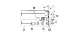
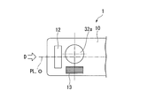
- FIG. 11 is a modification of the distal end portion in the endoscope apparatus that can observe a direction perpendicular to the central axis of the insertion portion.
- a distal end surface 10 b instead of the distal end surface 10 a, a distal end surface 10 b whose normal is a straight line perpendicular to the central axis of the insertion portion 10 is formed on a part of the outer peripheral surface of the distal end portion of the insertion portion 10.
- the illumination window 12, the projection window 13, and the cover member 32a are all disposed on the distal end surface 10b.
- the objective optical system 32 includes a prism 16 that directs the incident-side optical axis L1 in a direction intersecting the outgoing-side optical axis L2 from the objective optical system 32 toward the imager 31.
- the prism 16 is one of the optical elements constituting the objective optical system 32.
- the optical axis L1 on the incident side is an optical axis when the reflected light in the observation field enters the prism 16, and the optical axis L2 on the emission side reflects the reflected light in the observation field from the prism 16 to the imager 31. Is the optical axis when incident on the optical axis.
- the incident-side optical axis L ⁇ b> 1 is in a twisted position with respect to the central axis O of the insertion portion 10. Furthermore, the optical axis L2 on the emission side is parallel to the central axis O of the insertion portion 10.
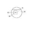
- FIG. 12A and 12B are views of the distal end surface 10b in the endoscope of FIG. 11 as viewed from a direction perpendicular to the distal end surface 10b, and are planes illustrating an arrangement example of the illumination window 12, the projection window 13, and the cover member 32a.
- FIG. 12A and 12B are views of the distal end surface 10b in the endoscope of FIG. 11 as viewed from a direction perpendicular to the distal end surface 10b, and are planes illustrating an arrangement example of the illumination window 12, the projection window 13, and the cover member 32a.
- the tip surface 10b is a substantially flat plane.
- the cover member 32a and the projection window 13 are arranged on the central axis O of the insertion portion 10 in plan view.
- the two illumination windows 12 are arranged on the side surface of the cover member 32a.
- Both the cover member 32a and the projection window 13 are exposed on the distal end surface 10b which is the outer peripheral surface of the distal end portion of the insertion portion.
- a line obtained by projecting the center axis O perpendicularly to the tip surface 10b is defined as a virtual center line PL. That is, in FIG.
- the cover member 32a and the projection window 13 are disposed at a position where their centers intersect with the virtual center line PL.
- the projection window 13 is a plane in which the center of the projection window when the projection window 13 is viewed from the thickness direction of the projection window 13 is defined by the central axis O of the insertion portion 10 and the optical axis L1 on the incident side. It is a positional relationship that exists within.
- the cover member 32a is arranged at a position where the center does not intersect with the virtual center line PL
- the illumination window 12 is arranged on the virtual center line PL of the insertion portion 10
- the projection window 13 further. May be arranged at a position where the center does not intersect with the virtual center line PL.
- FIGS. 12A and 12B are schematic views when the insertion portion 10 is viewed from the direction indicated by reference sign D in FIGS. 12A and 12B, respectively, and are front views of the insertion portion 10.
- the objective optical is set so that the optical axis L2 when the reflected light in the observation field enters the imager 31 from the prism 16 and the central axis O of the insertion portion 10 are decentered.
- a system 32 and an imager 31 are arranged.
- FIGS. 11 and 12A to 12D even in an example of an endoscope for observing the lateral direction, a case where projection windows 13 for projecting a light / dark pattern are provided at a plurality of positions as in the conventional case. In comparison, it is easy to reduce the diameter of the tip by having one projection window.
- positioned at a front end surface it is not restricted only to the example of FIG. 12A and FIG. 12B.
- the optical axis L1 and the optical axis L2 are orthogonal to each other is illustrated, but the optical axis L1 and the optical axis L2 may intersect at an angle other than orthogonal.
- the second light source 51 is provided on the distal end side of the insertion portion 10 as shown in FIG. 7, and is a high-luminance light source such as a laser.
- the second light source 51 is turned on while the first light source 41 is kept on based on a command from the main control unit 22, and an appropriate fringe is projected from one place onto the test object.
- the state that has been made may be referred to as a “stripe projection state”.
- the light amount is changed by controlling the second light source 51 without changing the phase of the light / dark pattern. Alternatively, stripe images with different stripe brightness may be taken.
- step S9 a bright field image captured before capturing N striped images and a bright field image captured after capturing N striped images are selected, and these The sum of the differences in luminance values between the two images is calculated. Further, in the above-described step S10, if the sum of the differences between the luminance values calculated in step S9 is smaller than the threshold value, it is determined that there is no blur between the first image and the subsequent image, and the process proceeds to step S11. move on. Conversely, if the sum of the differences between the brightness values calculated in step S9 is greater than the threshold value, it is determined that there is a blur between the first image and the subsequent image. Is displayed on the monitor 28 (step S14), and the series of processes is terminated.
- the above example is an example in which the difference is calculated over the entire image. Note that processing may be performed on only a part of the image. Alternatively, the luminance difference may be calculated using one bright field image and one striped image.
- the control operation by the main control unit 22 is different from that in the first embodiment and the first to ninth modifications.
- the second light source 51 (see FIG. 7) is composed of a plurality of minute light emitting elements. The plurality of light emitting elements provided in the second light source 51 are controlled to be turned on every two or more groups.
- the light / dark pattern generation unit 55 cannot change the stripe phase arbitrarily. It may be a board with, or something similar.
- step S5 a plurality of different stripes are projected onto the test object by sequentially switching the group of light emitting elements to be lit. Further, in step S6, each of these striped images can be taken.
- the first embodiment of the present invention has been described in detail with reference to the drawings. However, the specific configuration is not limited to this embodiment, and design changes and the like within the scope of the present invention are included. .
- a fringe image may be used as an image used for detecting blur. Absent.
- more than two bright field images can be taken. If there are more than two bright field images, the necessary number of images can be selected from these bright field images to detect blur. can do.
- the constituent elements shown in the first embodiment and the respective modifications can be combined as appropriate.
- FIG. 1 is a block diagram illustrating a configuration of an endoscope apparatus 1 according to the present embodiment.
- FIG. 2 is a schematic diagram showing a light / dark pattern projected by the endoscope apparatus 1. Note that the configuration of the endoscope apparatus of the second embodiment is the same as that of the endoscope apparatus of the first embodiment. Therefore, the same components as those in the first embodiment are denoted by the same reference numerals, and detailed description thereof is omitted.
- the measurement method of the second embodiment of the present invention will be described using an example in which measurement is performed using the endoscope apparatus 1 described above.
- the endoscope apparatus 1 when the endoscope apparatus 1 is used, first, the user uses the insertion portion 10 to access the test object such as the inside of the test object or a pipe line. The tip of the insertion portion 10 is advanced to a predetermined observation site. The user switches the observation mode for observing a desired part of the test object and the measurement mode for measuring the three-dimensional shape of the test part, as necessary, to inspect the test object.
- the light source control unit 21 controls the first light source 41 to be turned on and the second light source 51 to be turned off.
- the fringe pattern is not projected from the pattern projection unit 50, and the observation field is illuminated with white light from the illumination unit 40, and the observation field is illuminated (hereinafter, this illumination state is referred to as “observation state”).
- the illuminated image of the object is formed on the imager 31 through the objective optical system 32.
- the video signal sent from the imager 31 is processed by the video processor 27 and displayed on the monitor 28. The user can observe the test object from the image of the test object displayed on the monitor 28, and can store the image as necessary.
- the user When switching from the observation mode to the measurement mode, the user inputs an instruction to switch the mode.
- a known input device can be adopted as an input device for inputting an instruction for switching modes.
- a configuration in which a switch is provided in the operation unit 23 or a configuration in which the monitor 28 is changed to a touch panel to be a software switch can be employed.
- the main control unit 22 starts a measurement image photographing process (see FIG. 13).
- step S1 it is determined whether or not the endoscope apparatus 1 is in an observation state (step S1 shown in FIG. 13). If it is determined in step S1 that it is in the observation state, the process proceeds to step S3, and if it is in a state other than the observation state (for example, a measurement state described later) in step S1, the process proceeds to step S2. This ends step S1.
- Step S2 is a step of switching the endoscope apparatus 1 to the observation state.
- the first light source 41 is on-controlled and the second light source 51 is off-controlled.
- the pattern projection unit 50 does not project the fringe pattern, and the illumination unit 40 irradiates the observation field with white light, and the observation field is illuminated.
- Step S2 is complete
- Step S ⁇ b> 3 is a step of capturing an image of the test object that is not projected with the fringe pattern and is illuminated with white light from the illumination unit 40.
- step S ⁇ b> 3 an image is acquired by the imager 31 of the imaging unit 30 in a state where the test object is illuminated with white light from the illumination unit 40 (hereinafter, an image captured in the observation state is referred to as a “bright field image”). Called).
- the bright field image photographed in step S3 is temporarily stored in the RAM 24. Step S3 is completed now and it progresses to Step S16.
- Step S ⁇ b> 16 is a step of projecting a predetermined fringe pattern from one place of the endoscope apparatus 1 onto the test object.
- the first light source 41 is turned off and the second light source 51 is turned on based on a command from the main control unit 22.
- the white light irradiated from the illumination unit 40 is turned off, and the fringe pattern is projected from the pattern projection unit 50 onto the test object.
- the fringe pattern projected onto the test object is a pattern in which bright portions R ⁇ b> 1 due to a white light source and dark portions R ⁇ b> 2 shielded by the pattern generation unit 55 are alternately arranged. (Hereinafter, this state is referred to as a “pattern projection state”).
- Step S16 is ended now and it progresses to Step S17.
- Step S17 is a step of capturing a pattern projection image in the pattern projection state.
- the fringe pattern projected onto the test object is a pattern that changes according to the three-dimensional shape of the test object.
- one image is acquired by the imager 31 of the imaging unit 30 (hereinafter, an image photographed in the pattern projection state is referred to as a “pattern projection image”).
- the pattern projection image photographed in step S17 is temporarily stored in the RAM 24. Step S17 is ended now and it progresses to Step S18.
- Step S18 is a step of switching the endoscope apparatus 1 to the observation state.
- the first light source 41 is on-controlled and the second light source 51 is off-controlled.
- the pattern projection unit 50 does not project the fringe pattern, and the illumination unit 40 irradiates the observation field with white light, and the observation field is illuminated.
- Step S18 is completed now and it progresses to Step S19.
- Step S ⁇ b> 19 is a step of capturing an image of the test object that is not projected with the stripe pattern and is illuminated with white light from the illumination unit 40.
- step S ⁇ b> 19 a bright field image is captured by the imager 31 of the imaging unit 30 in a state where the test object is illuminated with white light from the illumination unit 40.
- the bright field image photographed in step S19 is temporarily stored in the RAM 24. Step S19 is completed now and it progresses to Step S20.
- step S20 relative movement between the insertion unit 10 and the test object between step S3 and step S19 is performed based on the images (bright field image and pattern projection image) taken between step S3 and step S19.
- images (bright field image and pattern projection image) taken between step S3 and step S19.
- blue the images taken between step S3 and step S19.
- step S20 first, two images are selected from at least one of the bright field image and the pattern projection image stored in the RAM 24. For example, in the second embodiment, a bright field image captured before capturing one pattern projection image and a bright field image captured after capturing one pattern projection image are selected. Subsequently, the same feature point is detected from the two selected images, and the coordinates of the feature point in the two images are calculated. Step S20 is ended now and it progresses to Step S21.
- Step S21 is a step of branching the processing by determining blurring of the two images using the feature points detected in step S20.
- step S21 if the coordinates of the feature points in the two images are the same in each image, it is determined that there is no blur between the first image and the subsequent image, and the process proceeds to step S22.
- step S25 if the coordinates of the feature points in the two images are different in each image, it is determined that there is a blur between the first image and the subsequent image, and a blur has occurred. Is displayed on the monitor 28 (step S25), and the series of processes is terminated. This ends step S21.
- Step S22 is a step in which the user selects whether to perform the three-dimensional measurement using the captured pattern projection image now or later.
- step S22 for example, an inquiry such as “Perform measurement?” Is displayed on the monitor 28, and the user is prompted to input whether or not to perform three-dimensional measurement using the captured pattern projection image. If there is an input that the measurement can be performed, the process proceeds to step S23. If there is an input that the measurement is not performed, the process proceeds to step S26. Step S22 is complete
- Step S23 is a step of performing analysis for performing three-dimensional measurement.
- the three-dimensional shape is analyzed based on the pattern projection image stored in the RAM 24.
- the three-dimensional shape of the test object is analyzed by using, for example, a known spatial phase shift method or Fourier transform method using one pattern projection image.
- the analysis result of the three-dimensional shape is generated as a text file or a binary file, and is stored in the auxiliary storage device 25 together with the pattern projection image.
- step S23 may be performed as the background process of step S22 simultaneously with the start of step S22. Step S23 is ended now and it progresses to Step S24.
- step S24 the display on the monitor 28 is shifted to the screen of various measurement modes, and the measurement result is displayed on the monitor 28 using the information stored in step S23.
- step S24 the test object displayed in the bright field image is overlaid on the bright field image acquired in step S3 (or the bright field image acquired in step S19) by overlaying the result analyzed in step S23.
- the three-dimensional shape is displayed on the monitor 28. Thereby, the user can know the three-dimensional shape of the test object.
- Step S24 is complete
- Step S26 is a step branched from step S22, and is a step for performing information processing necessary for displaying the measurement result later.
- the three-dimensional shape is analyzed based on the pattern projection image stored in the RAM 24, as in step S23.
- the three-dimensional shape of the test object is analyzed by the spatial phase shift method or the Fourier transform method using one pattern projection image.
- the bright field image, the pattern projection image, the analysis result of the three-dimensional shape, and the optical parameters used for the analysis are stored in the auxiliary storage device 25 as a binary file or a text file, respectively.
- Step S26 is complete
- the test object is based on one pattern projection image photographed in a state where a predetermined fringe pattern is projected onto the test object. Since the three-dimensional shape can be measured, the three-dimensional shape can be measured in a short time using the endoscope apparatus 1.
- the measurement method of the second embodiment of the present invention even in an environment in which a fringe pattern is projected from one projection window 13 in the endoscope apparatus 1 in which the insertion portion 10 is reduced in diameter, it is accurate. A three-dimensional shape can be measured.
- a bright-field image can be taken, and blur can be detected using two images selected from the pattern projection image and the bright-field image. Accuracy can be increased.
- blur is detected using bright field images before and after pattern projection images are taken, and when it is determined that there is no blur, a three-dimensional shape is analyzed.
- the analysis is not performed while the fringe patterns on the plurality of pattern projection images are shifted. For this reason, the analysis precision of a three-dimensional shape can be improved. Further, it is possible to suppress a positional deviation when the measurement result using the pattern projection image is displayed as an overlay on the bright field image.
- the method for measuring the three-dimensional shape of the test object is different.
- the measurement method of the present modification will be described focusing on the point of difference in processing content from the above-described second embodiment.
- step S23 and step S26 a three-dimensional shape is analyzed by a light cutting method using one pattern projection image.
- a three-dimensional shape is analyzed on a single pattern using a single pattern projection image. Therefore, compared to the case where the entire surface of one pattern projection image is analyzed in the above-described embodiment, the portion where the three-dimensional shape can be measured is limited, but the analysis time can be greatly shortened.
- the second embodiment of the present invention has been described in detail with reference to the drawings. However, the specific configuration is not limited to this embodiment, and design changes and the like within a scope not departing from the gist of the present invention are included. .
- an example of capturing one pattern projection image has been described. However, a plurality of pattern projection images are captured, and one pattern projection image with a good image state is captured. By selecting, substantially one pattern projection image may be acquired and used for analysis.
- a pattern projection image may be used as an image used for detecting blur. I do not care. Also, more than two bright field images can be taken. If there are more than two bright field images, the necessary number of images can be selected from these bright field images to detect blur. can do.
- the diameter of the insertion portion can be reduced.
- a three-dimensional shape can be measured with high accuracy even in an endoscope apparatus in which the insertion portion has a reduced diameter.
- the three-dimensional shape measurement method of the endoscope apparatus the three-dimensional shape can be measured by analyzing one striped image photographed using the endoscope apparatus. The three-dimensional shape can be measured in a short time using the endoscope apparatus.
Landscapes
- Health & Medical Sciences (AREA)
- Life Sciences & Earth Sciences (AREA)
- Physics & Mathematics (AREA)
- Surgery (AREA)
- Engineering & Computer Science (AREA)
- Heart & Thoracic Surgery (AREA)
- Molecular Biology (AREA)
- Veterinary Medicine (AREA)
- Public Health (AREA)
- General Health & Medical Sciences (AREA)
- Animal Behavior & Ethology (AREA)
- Biophysics (AREA)
- Pathology (AREA)
- Biomedical Technology (AREA)
- Medical Informatics (AREA)
- Optics & Photonics (AREA)
- Radiology & Medical Imaging (AREA)
- Nuclear Medicine, Radiotherapy & Molecular Imaging (AREA)
- General Physics & Mathematics (AREA)
- Oral & Maxillofacial Surgery (AREA)
- Dentistry (AREA)
- Astronomy & Astrophysics (AREA)
- Signal Processing (AREA)
- Computer Vision & Pattern Recognition (AREA)
- Theoretical Computer Science (AREA)
- Multimedia (AREA)
- Endoscopes (AREA)
- Instruments For Viewing The Inside Of Hollow Bodies (AREA)
Abstract
La présente invention concerne un dispositif endoscopique et un procédé de mesure destinés à réaliser des mesures sur des sujets en utilisant des images de projection de profil, un profil de frange étant projeté sur le sujet. Ledit dispositif endoscopique est équipé : d'une longue partie d'insertion (10) ; d'une partie de prise d'image (30), qui est prévue sur la pointe de la partie d'insertion (10) et acquiert des images du sujet ; d'une partie d'éclairage (40) qui est prévue sur l'extrémité de la partie d'insertion (10) et génère la lumière d'éclairage qui éclaire le champ de vision de la partie de prise d'image (30) ; et d'une partie de projection de profil (50), qui est prévue sur la pointe de la partie d'insertion (10) et projette un profil de franche sur le sujet. La surface de la pointe (10a) de la partie d'insertion (10) est dotée d'un système optique d'objectif (32) qui forme des images sur le sujet de la partie de prise d'images (30), une ou plusieurs fenêtres d'éclairage (12) qui émettent la lumière d'éclairage, et une fenêtre de projection (13) qui projette le profil de frange de la partie de projection de profil (50) sur le sujet.
Priority Applications (4)
| Application Number | Priority Date | Filing Date | Title |
|---|---|---|---|
| EP12777405.7A EP2689708B1 (fr) | 2011-04-27 | 2012-04-23 | Dispositif endoscopique et procédé de mesure |
| US14/061,530 US20140052005A1 (en) | 2011-04-27 | 2013-10-23 | Endoscope apparatus and measuring method |
| US15/423,043 US10342459B2 (en) | 2011-04-27 | 2017-02-02 | Endoscope apparatus and measuring method |
| US16/427,001 US10898110B2 (en) | 2011-04-27 | 2019-05-30 | Endoscope apparatus and measuring method |
Applications Claiming Priority (4)
| Application Number | Priority Date | Filing Date | Title |
|---|---|---|---|
| JP2011099890A JP6032870B2 (ja) | 2011-04-27 | 2011-04-27 | 計測方法 |
| JP2011-099890 | 2011-04-27 | ||
| JP2011099889A JP5893264B2 (ja) | 2011-04-27 | 2011-04-27 | 内視鏡装置 |
| JP2011-099889 | 2011-04-27 |
Related Child Applications (1)
| Application Number | Title | Priority Date | Filing Date |
|---|---|---|---|
| US14/061,530 Continuation US20140052005A1 (en) | 2011-04-27 | 2013-10-23 | Endoscope apparatus and measuring method |
Publications (1)
| Publication Number | Publication Date |
|---|---|
| WO2012147679A1 true WO2012147679A1 (fr) | 2012-11-01 |
Family
ID=47072198
Family Applications (1)
| Application Number | Title | Priority Date | Filing Date |
|---|---|---|---|
| PCT/JP2012/060832 WO2012147679A1 (fr) | 2011-04-27 | 2012-04-23 | Dispositif endoscopique et procédé de mesure |
Country Status (3)
| Country | Link |
|---|---|
| US (3) | US20140052005A1 (fr) |
| EP (1) | EP2689708B1 (fr) |
| WO (1) | WO2012147679A1 (fr) |
Cited By (1)
| Publication number | Priority date | Publication date | Assignee | Title |
|---|---|---|---|---|
| US9545220B2 (en) | 2014-03-02 | 2017-01-17 | V.T.M (Virtual Tape Measure) Technologies Ltd. | Endoscopic measurement system and method |
Families Citing this family (33)
| Publication number | Priority date | Publication date | Assignee | Title |
|---|---|---|---|---|
| US9943372B2 (en) | 2005-04-18 | 2018-04-17 | M.S.T. Medical Surgery Technologies Ltd. | Device having a wearable interface for improving laparoscopic surgery and methods for use thereof |
| EP2689708B1 (fr) | 2011-04-27 | 2016-10-19 | Olympus Corporation | Dispositif endoscopique et procédé de mesure |
| JP5830270B2 (ja) | 2011-05-24 | 2015-12-09 | オリンパス株式会社 | 内視鏡装置および計測方法 |
| JP5846763B2 (ja) | 2011-05-24 | 2016-01-20 | オリンパス株式会社 | 内視鏡装置 |
| US11561762B2 (en) * | 2011-08-21 | 2023-01-24 | Asensus Surgical Europe S.A.R.L. | Vocally actuated surgical control system |
| US9204939B2 (en) | 2011-08-21 | 2015-12-08 | M.S.T. Medical Surgery Technologies Ltd. | Device and method for assisting laparoscopic surgery—rule based approach |
| US9757206B2 (en) | 2011-08-21 | 2017-09-12 | M.S.T. Medical Surgery Technologies Ltd | Device and method for assisting laparoscopic surgery—rule based approach |
| US10866783B2 (en) | 2011-08-21 | 2020-12-15 | Transenterix Europe S.A.R.L. | Vocally activated surgical control system |
| US9795282B2 (en) | 2011-09-20 | 2017-10-24 | M.S.T. Medical Surgery Technologies Ltd | Device and method for maneuvering endoscope |
| US20150238276A1 (en) * | 2012-09-30 | 2015-08-27 | M.S.T. Medical Surgery Technologies Ltd. | Device and method for assisting laparoscopic surgery - directing and maneuvering articulating tool |
| CN106028930B (zh) | 2014-02-21 | 2021-10-22 | 3D集成公司 | 包括手术器械的套件 |
| US11116383B2 (en) * | 2014-04-02 | 2021-09-14 | Asensus Surgical Europe S.à.R.L. | Articulated structured light based-laparoscope |
| EP3145419B1 (fr) | 2015-07-21 | 2019-11-27 | 3dintegrated ApS | Kit de montage de canule, kit de montage de trocart et système de chirurgie mini-invasive |
| US11020144B2 (en) | 2015-07-21 | 2021-06-01 | 3Dintegrated Aps | Minimally invasive surgery system |
| DK178899B1 (en) | 2015-10-09 | 2017-05-08 | 3Dintegrated Aps | A depiction system |
| US20180042466A1 (en) * | 2016-08-12 | 2018-02-15 | The Johns Hopkins University | Compact endoscope design for three-dimensional surgical guidance |
| EP3544482A4 (fr) | 2016-11-28 | 2020-07-22 | Adaptivendo LLC | Endoscope à arbre jetable séparable |
| EP3845116B1 (fr) | 2017-02-01 | 2023-06-21 | Boston Scientific Scimed, Inc. | Endoscope a plusieurs directions de visualisation |
| EP3599982A4 (fr) | 2017-03-20 | 2020-12-23 | 3dintegrated ApS | Système de reconstruction 3d |
| WO2018229833A1 (fr) | 2017-06-12 | 2018-12-20 | オリンパス株式会社 | Système d'endoscope |
| WO2018229831A1 (fr) * | 2017-06-12 | 2018-12-20 | オリンパス株式会社 | Système d'endoscope |
| WO2018229834A1 (fr) * | 2017-06-12 | 2018-12-20 | オリンパス株式会社 | Système d'endoscope |
| WO2018229832A1 (fr) | 2017-06-12 | 2018-12-20 | オリンパス株式会社 | Système d'endoscope |
| CN112236067A (zh) | 2018-06-05 | 2021-01-15 | 奥林巴斯株式会社 | 内窥镜系统 |
| JP7093409B2 (ja) | 2018-06-05 | 2022-06-29 | オリンパス株式会社 | 内視鏡システム |
| KR102545980B1 (ko) | 2018-07-19 | 2023-06-21 | 액티브 서지컬, 인크. | 자동화된 수술 로봇을 위한 비전 시스템에서 깊이의 다중 모달 감지를 위한 시스템 및 방법 |
| KR20220021920A (ko) | 2019-04-08 | 2022-02-22 | 액티브 서지컬, 인크. | 의료 이미징을 위한 시스템 및 방법 |
| US11903563B2 (en) | 2019-06-20 | 2024-02-20 | Cilag Gmbh International | Offset illumination of a scene using multiple emitters in a fluorescence imaging system |
| US11550057B2 (en) | 2019-06-20 | 2023-01-10 | Cilag Gmbh International | Offset illumination of a scene using multiple emitters in a fluorescence imaging system |
| US11589819B2 (en) | 2019-06-20 | 2023-02-28 | Cilag Gmbh International | Offset illumination of a scene using multiple emitters in a laser mapping imaging system |
| US11931009B2 (en) | 2019-06-20 | 2024-03-19 | Cilag Gmbh International | Offset illumination of a scene using multiple emitters in a hyperspectral imaging system |
| EP4017340A4 (fr) | 2019-08-21 | 2023-12-13 | Activ Surgical, Inc. | Systèmes et procédés d'imagerie médicale |
| USD1018844S1 (en) | 2020-01-09 | 2024-03-19 | Adaptivendo Llc | Endoscope handle |
Citations (5)
| Publication number | Priority date | Publication date | Assignee | Title |
|---|---|---|---|---|
| JPH02287311A (ja) * | 1989-04-28 | 1990-11-27 | Toshiba Corp | 計測機構付内視鏡装置 |
| JPH10239031A (ja) * | 1997-02-28 | 1998-09-11 | Olympus Optical Co Ltd | 三次元計測装置 |
| JP2007139822A (ja) * | 2005-11-14 | 2007-06-07 | Olympus Corp | 内視鏡装置 |
| JP2009019941A (ja) * | 2007-07-11 | 2009-01-29 | Nikon Corp | 形状測定方法 |
| US20090225321A1 (en) | 2008-03-05 | 2009-09-10 | Clark Alexander Bendall | Fringe projection system and method for a probe suitable for phase-shift analysis |
Family Cites Families (32)
| Publication number | Priority date | Publication date | Assignee | Title |
|---|---|---|---|---|
| JPH0664243B2 (ja) * | 1986-04-30 | 1994-08-22 | オリンパス光学工業株式会社 | 内視鏡 |
| JPH07104493B2 (ja) | 1987-02-17 | 1995-11-13 | オリンパス光学工業株式会社 | 内視鏡装置 |
| JPH07104491B2 (ja) | 1988-02-17 | 1995-11-13 | 株式会社東芝 | 計測機能付き内視鏡装置 |
| JPH0285706A (ja) | 1988-09-22 | 1990-03-27 | Toshiba Corp | 計測内視鏡 |
| US4995396A (en) * | 1988-12-08 | 1991-02-26 | Olympus Optical Co., Ltd. | Radioactive ray detecting endoscope |
| JPH03128043A (ja) | 1989-10-16 | 1991-05-31 | Toshiba Corp | 形状計測内視鏡装置 |
| US5434669A (en) * | 1990-10-23 | 1995-07-18 | Olympus Optical Co., Ltd. | Measuring interferometric endoscope having a laser radiation source |
| US5436655A (en) * | 1991-08-09 | 1995-07-25 | Olympus Optical Co., Ltd. | Endoscope apparatus for three dimensional measurement for scanning spot light to execute three dimensional measurement |
| JPH0545132A (ja) | 1991-08-15 | 1993-02-23 | Olympus Optical Co Ltd | 計測用内視鏡装置 |
| JP3126065B2 (ja) | 1991-12-09 | 2001-01-22 | オリンパス光学工業株式会社 | 計測用内視鏡装置 |
| JPH0961132A (ja) | 1995-08-28 | 1997-03-07 | Olympus Optical Co Ltd | 3次元形状計測装置 |
| JP3670789B2 (ja) | 1997-02-28 | 2005-07-13 | オリンパス株式会社 | 三次元形状計測装置 |
| US6419626B1 (en) | 1998-08-12 | 2002-07-16 | Inbae Yoon | Surgical instrument endoscope with CMOS image sensor and physical parameter sensor |
| US6464633B1 (en) * | 1999-08-23 | 2002-10-15 | Olympus Optical Co., Ltd. | Light source device for endoscope using DMD |
| DE10104483A1 (de) * | 2001-01-31 | 2002-10-10 | Forschungszentrum Fuer Medizin | Vorrichtung zur dreidimensionalen Vermessung von Oberflächen in Hohlräumen |
| US7385708B2 (en) | 2002-06-07 | 2008-06-10 | The University Of North Carolina At Chapel Hill | Methods and systems for laser based real-time structured light depth extraction |
| JP4229791B2 (ja) | 2003-09-19 | 2009-02-25 | 真 金子 | 内視鏡装置 |
| JP2007144024A (ja) | 2005-11-30 | 2007-06-14 | National Univ Corp Shizuoka Univ | 自己混合レーザを用いる三次元計測内視鏡 |
| WO2007102195A1 (fr) | 2006-03-07 | 2007-09-13 | Fujitsu Limited | Appareil d'imagerie et méthode d'imagerie |
| JP5436757B2 (ja) | 2007-03-20 | 2014-03-05 | オリンパス株式会社 | 蛍光観察装置 |
| JP5049677B2 (ja) * | 2007-07-10 | 2012-10-17 | 京セラドキュメントソリューションズ株式会社 | 廃棄トナー回収装置及びこれを搭載した画像形成装置 |
| JP2009061014A (ja) | 2007-09-05 | 2009-03-26 | Fujifilm Corp | 硬さ測定装置、硬さ測定方法、および内視鏡システム |
| US8107083B2 (en) * | 2008-03-05 | 2012-01-31 | General Electric Company | System aspects for a probe system that utilizes structured-light |
| JP2009240621A (ja) | 2008-03-31 | 2009-10-22 | Hoya Corp | 内視鏡装置 |
| JP5073564B2 (ja) | 2008-04-15 | 2012-11-14 | オリンパス株式会社 | 計測用内視鏡装置およびプログラム |
| US8334900B2 (en) | 2008-07-21 | 2012-12-18 | The Hong Kong University Of Science And Technology | Apparatus and method of optical imaging for medical diagnosis |
| JP5127639B2 (ja) | 2008-09-10 | 2013-01-23 | 富士フイルム株式会社 | 内視鏡システム、およびその作動方法 |
| EP2272417B1 (fr) | 2009-07-10 | 2016-11-09 | GE Inspection Technologies, LP | Système de projection de frange pour sonde adapté à une analyse de commutation de phase |
| JP2011229850A (ja) | 2010-04-30 | 2011-11-17 | Fujifilm Corp | 内視鏡装置、方法およびプログラム |
| EP2689708B1 (fr) | 2011-04-27 | 2016-10-19 | Olympus Corporation | Dispositif endoscopique et procédé de mesure |
| JP5846763B2 (ja) | 2011-05-24 | 2016-01-20 | オリンパス株式会社 | 内視鏡装置 |
| JP5830270B2 (ja) | 2011-05-24 | 2015-12-09 | オリンパス株式会社 | 内視鏡装置および計測方法 |
-
2012
- 2012-04-23 EP EP12777405.7A patent/EP2689708B1/fr active Active
- 2012-04-23 WO PCT/JP2012/060832 patent/WO2012147679A1/fr active Application Filing
-
2013
- 2013-10-23 US US14/061,530 patent/US20140052005A1/en not_active Abandoned
-
2017
- 2017-02-02 US US15/423,043 patent/US10342459B2/en active Active
-
2019
- 2019-05-30 US US16/427,001 patent/US10898110B2/en active Active
Patent Citations (5)
| Publication number | Priority date | Publication date | Assignee | Title |
|---|---|---|---|---|
| JPH02287311A (ja) * | 1989-04-28 | 1990-11-27 | Toshiba Corp | 計測機構付内視鏡装置 |
| JPH10239031A (ja) * | 1997-02-28 | 1998-09-11 | Olympus Optical Co Ltd | 三次元計測装置 |
| JP2007139822A (ja) * | 2005-11-14 | 2007-06-07 | Olympus Corp | 内視鏡装置 |
| JP2009019941A (ja) * | 2007-07-11 | 2009-01-29 | Nikon Corp | 形状測定方法 |
| US20090225321A1 (en) | 2008-03-05 | 2009-09-10 | Clark Alexander Bendall | Fringe projection system and method for a probe suitable for phase-shift analysis |
Non-Patent Citations (1)
| Title |
|---|
| See also references of EP2689708A4 |
Cited By (1)
| Publication number | Priority date | Publication date | Assignee | Title |
|---|---|---|---|---|
| US9545220B2 (en) | 2014-03-02 | 2017-01-17 | V.T.M (Virtual Tape Measure) Technologies Ltd. | Endoscopic measurement system and method |
Also Published As
| Publication number | Publication date |
|---|---|
| US20170143237A1 (en) | 2017-05-25 |
| EP2689708B1 (fr) | 2016-10-19 |
| US10898110B2 (en) | 2021-01-26 |
| EP2689708A1 (fr) | 2014-01-29 |
| EP2689708A4 (fr) | 2014-06-18 |
| US20140052005A1 (en) | 2014-02-20 |
| US20190274591A1 (en) | 2019-09-12 |
| US10342459B2 (en) | 2019-07-09 |
Similar Documents
| Publication | Publication Date | Title |
|---|---|---|
| WO2012147679A1 (fr) | Dispositif endoscopique et procédé de mesure | |
| JP5841353B2 (ja) | 内視鏡装置および画像取得方法 | |
| US10368721B2 (en) | Endoscope | |
| JP5972563B2 (ja) | 構造化照明を用いるエッジ検出 | |
| WO2012161244A1 (fr) | Dispositif d'endoscope, et procédé de mesure | |
| US20090231983A1 (en) | Image pickup apparatus for capturing spectral images of an object and observation system including the same | |
| US11426052B2 (en) | Endoscopic system | |
| JP6945415B2 (ja) | 画像測定装置の調整方法 | |
| JP5893264B2 (ja) | 内視鏡装置 | |
| JPH07136101A (ja) | 計測機能付き内視鏡 | |
| JP6706026B2 (ja) | 内視鏡システムおよび内視鏡装置の作動方法 | |
| JP6032870B2 (ja) | 計測方法 | |
| JP2008125989A (ja) | 内視鏡ポイント光照射位置調整システム | |
| WO2014045581A1 (fr) | Dispositif de mesure optique et système de sonde | |
| JP2008125996A (ja) | 内視鏡被写体距離測定システム | |
| JP6574101B2 (ja) | 内視鏡システム | |
| JPWO2018198908A1 (ja) | 毛髪観察方法、位相差顕微鏡システム及びプレパラート | |
| JP2009180708A (ja) | 形状測定方法及び形状測定装置 | |
| JP5922556B2 (ja) | 溶接検査装置及び溶接検査方法 | |
| US11648080B2 (en) | Medical observation control device and medical observation system that correct brightness differences between images acquired at different timings | |
| US20230032656A1 (en) | Chromatic range sensor system including camera | |
| JP5356187B2 (ja) | レンズの球欠高さ測定方法および装置 | |
| WO2017064746A1 (fr) | Dispositif d'imagerie, dispositif endoscopique et procédé d'imagerie |
Legal Events
| Date | Code | Title | Description |
|---|---|---|---|
| 121 | Ep: the epo has been informed by wipo that ep was designated in this application |
Ref document number: 12777405 Country of ref document: EP Kind code of ref document: A1 |
|
| REEP | Request for entry into the european phase |
Ref document number: 2012777405 Country of ref document: EP |
|
| WWE | Wipo information: entry into national phase |
Ref document number: 2012777405 Country of ref document: EP |
|
| NENP | Non-entry into the national phase |
Ref country code: DE |