WO2012147603A1 - 薄型表示装置 - Google Patents
薄型表示装置 Download PDFInfo
- Publication number
- WO2012147603A1 WO2012147603A1 PCT/JP2012/060557 JP2012060557W WO2012147603A1 WO 2012147603 A1 WO2012147603 A1 WO 2012147603A1 JP 2012060557 W JP2012060557 W JP 2012060557W WO 2012147603 A1 WO2012147603 A1 WO 2012147603A1
- Authority
- WO
- WIPO (PCT)
- Prior art keywords
- frame
- restricting
- display device
- bending
- thin display
- Prior art date
Links
Images


Classifications
-
- G—PHYSICS
- G02—OPTICS
- G02F—OPTICAL DEVICES OR ARRANGEMENTS FOR THE CONTROL OF LIGHT BY MODIFICATION OF THE OPTICAL PROPERTIES OF THE MEDIA OF THE ELEMENTS INVOLVED THEREIN; NON-LINEAR OPTICS; FREQUENCY-CHANGING OF LIGHT; OPTICAL LOGIC ELEMENTS; OPTICAL ANALOGUE/DIGITAL CONVERTERS
- G02F1/00—Devices or arrangements for the control of the intensity, colour, phase, polarisation or direction of light arriving from an independent light source, e.g. switching, gating or modulating; Non-linear optics
- G02F1/01—Devices or arrangements for the control of the intensity, colour, phase, polarisation or direction of light arriving from an independent light source, e.g. switching, gating or modulating; Non-linear optics for the control of the intensity, phase, polarisation or colour
- G02F1/13—Devices or arrangements for the control of the intensity, colour, phase, polarisation or direction of light arriving from an independent light source, e.g. switching, gating or modulating; Non-linear optics for the control of the intensity, phase, polarisation or colour based on liquid crystals, e.g. single liquid crystal display cells
- G02F1/133—Constructional arrangements; Operation of liquid crystal cells; Circuit arrangements
- G02F1/1333—Constructional arrangements; Manufacturing methods
- G02F1/133308—Support structures for LCD panels, e.g. frames or bezels
-
- H—ELECTRICITY
- H04—ELECTRIC COMMUNICATION TECHNIQUE
- H04N—PICTORIAL COMMUNICATION, e.g. TELEVISION
- H04N5/00—Details of television systems
- H04N5/64—Constructional details of receivers, e.g. cabinets or dust covers
-
- G—PHYSICS
- G02—OPTICS
- G02F—OPTICAL DEVICES OR ARRANGEMENTS FOR THE CONTROL OF LIGHT BY MODIFICATION OF THE OPTICAL PROPERTIES OF THE MEDIA OF THE ELEMENTS INVOLVED THEREIN; NON-LINEAR OPTICS; FREQUENCY-CHANGING OF LIGHT; OPTICAL LOGIC ELEMENTS; OPTICAL ANALOGUE/DIGITAL CONVERTERS
- G02F1/00—Devices or arrangements for the control of the intensity, colour, phase, polarisation or direction of light arriving from an independent light source, e.g. switching, gating or modulating; Non-linear optics
- G02F1/01—Devices or arrangements for the control of the intensity, colour, phase, polarisation or direction of light arriving from an independent light source, e.g. switching, gating or modulating; Non-linear optics for the control of the intensity, phase, polarisation or colour
- G02F1/13—Devices or arrangements for the control of the intensity, colour, phase, polarisation or direction of light arriving from an independent light source, e.g. switching, gating or modulating; Non-linear optics for the control of the intensity, phase, polarisation or colour based on liquid crystals, e.g. single liquid crystal display cells
- G02F1/133—Constructional arrangements; Operation of liquid crystal cells; Circuit arrangements
- G02F1/1333—Constructional arrangements; Manufacturing methods
- G02F1/133308—Support structures for LCD panels, e.g. frames or bezels
- G02F1/133311—Environmental protection, e.g. against dust or humidity
-
- G—PHYSICS
- G02—OPTICS
- G02F—OPTICAL DEVICES OR ARRANGEMENTS FOR THE CONTROL OF LIGHT BY MODIFICATION OF THE OPTICAL PROPERTIES OF THE MEDIA OF THE ELEMENTS INVOLVED THEREIN; NON-LINEAR OPTICS; FREQUENCY-CHANGING OF LIGHT; OPTICAL LOGIC ELEMENTS; OPTICAL ANALOGUE/DIGITAL CONVERTERS
- G02F1/00—Devices or arrangements for the control of the intensity, colour, phase, polarisation or direction of light arriving from an independent light source, e.g. switching, gating or modulating; Non-linear optics
- G02F1/01—Devices or arrangements for the control of the intensity, colour, phase, polarisation or direction of light arriving from an independent light source, e.g. switching, gating or modulating; Non-linear optics for the control of the intensity, phase, polarisation or colour
- G02F1/13—Devices or arrangements for the control of the intensity, colour, phase, polarisation or direction of light arriving from an independent light source, e.g. switching, gating or modulating; Non-linear optics for the control of the intensity, phase, polarisation or colour based on liquid crystals, e.g. single liquid crystal display cells
- G02F1/133—Constructional arrangements; Operation of liquid crystal cells; Circuit arrangements
- G02F1/1333—Constructional arrangements; Manufacturing methods
- G02F1/133308—Support structures for LCD panels, e.g. frames or bezels
- G02F1/13332—Front frames
-
- G—PHYSICS
- G02—OPTICS
- G02F—OPTICAL DEVICES OR ARRANGEMENTS FOR THE CONTROL OF LIGHT BY MODIFICATION OF THE OPTICAL PROPERTIES OF THE MEDIA OF THE ELEMENTS INVOLVED THEREIN; NON-LINEAR OPTICS; FREQUENCY-CHANGING OF LIGHT; OPTICAL LOGIC ELEMENTS; OPTICAL ANALOGUE/DIGITAL CONVERTERS
- G02F1/00—Devices or arrangements for the control of the intensity, colour, phase, polarisation or direction of light arriving from an independent light source, e.g. switching, gating or modulating; Non-linear optics
- G02F1/01—Devices or arrangements for the control of the intensity, colour, phase, polarisation or direction of light arriving from an independent light source, e.g. switching, gating or modulating; Non-linear optics for the control of the intensity, phase, polarisation or colour
- G02F1/13—Devices or arrangements for the control of the intensity, colour, phase, polarisation or direction of light arriving from an independent light source, e.g. switching, gating or modulating; Non-linear optics for the control of the intensity, phase, polarisation or colour based on liquid crystals, e.g. single liquid crystal display cells
- G02F1/133—Constructional arrangements; Operation of liquid crystal cells; Circuit arrangements
- G02F1/1333—Constructional arrangements; Manufacturing methods
- G02F1/133308—Support structures for LCD panels, e.g. frames or bezels
- G02F1/133322—Mechanical guidance or alignment of LCD panel support components
-
- G—PHYSICS
- G02—OPTICS
- G02F—OPTICAL DEVICES OR ARRANGEMENTS FOR THE CONTROL OF LIGHT BY MODIFICATION OF THE OPTICAL PROPERTIES OF THE MEDIA OF THE ELEMENTS INVOLVED THEREIN; NON-LINEAR OPTICS; FREQUENCY-CHANGING OF LIGHT; OPTICAL LOGIC ELEMENTS; OPTICAL ANALOGUE/DIGITAL CONVERTERS
- G02F1/00—Devices or arrangements for the control of the intensity, colour, phase, polarisation or direction of light arriving from an independent light source, e.g. switching, gating or modulating; Non-linear optics
- G02F1/01—Devices or arrangements for the control of the intensity, colour, phase, polarisation or direction of light arriving from an independent light source, e.g. switching, gating or modulating; Non-linear optics for the control of the intensity, phase, polarisation or colour
- G02F1/13—Devices or arrangements for the control of the intensity, colour, phase, polarisation or direction of light arriving from an independent light source, e.g. switching, gating or modulating; Non-linear optics for the control of the intensity, phase, polarisation or colour based on liquid crystals, e.g. single liquid crystal display cells
- G02F1/133—Constructional arrangements; Operation of liquid crystal cells; Circuit arrangements
- G02F1/1333—Constructional arrangements; Manufacturing methods
- G02F1/133308—Support structures for LCD panels, e.g. frames or bezels
- G02F1/133325—Assembling processes
-
- G—PHYSICS
- G02—OPTICS
- G02F—OPTICAL DEVICES OR ARRANGEMENTS FOR THE CONTROL OF LIGHT BY MODIFICATION OF THE OPTICAL PROPERTIES OF THE MEDIA OF THE ELEMENTS INVOLVED THEREIN; NON-LINEAR OPTICS; FREQUENCY-CHANGING OF LIGHT; OPTICAL LOGIC ELEMENTS; OPTICAL ANALOGUE/DIGITAL CONVERTERS
- G02F1/00—Devices or arrangements for the control of the intensity, colour, phase, polarisation or direction of light arriving from an independent light source, e.g. switching, gating or modulating; Non-linear optics
- G02F1/01—Devices or arrangements for the control of the intensity, colour, phase, polarisation or direction of light arriving from an independent light source, e.g. switching, gating or modulating; Non-linear optics for the control of the intensity, phase, polarisation or colour
- G02F1/13—Devices or arrangements for the control of the intensity, colour, phase, polarisation or direction of light arriving from an independent light source, e.g. switching, gating or modulating; Non-linear optics for the control of the intensity, phase, polarisation or colour based on liquid crystals, e.g. single liquid crystal display cells
- G02F1/133—Constructional arrangements; Operation of liquid crystal cells; Circuit arrangements
- G02F1/1333—Constructional arrangements; Manufacturing methods
- G02F1/133308—Support structures for LCD panels, e.g. frames or bezels
- G02F1/133328—Segmented frames
-
- G—PHYSICS
- G02—OPTICS
- G02F—OPTICAL DEVICES OR ARRANGEMENTS FOR THE CONTROL OF LIGHT BY MODIFICATION OF THE OPTICAL PROPERTIES OF THE MEDIA OF THE ELEMENTS INVOLVED THEREIN; NON-LINEAR OPTICS; FREQUENCY-CHANGING OF LIGHT; OPTICAL LOGIC ELEMENTS; OPTICAL ANALOGUE/DIGITAL CONVERTERS
- G02F1/00—Devices or arrangements for the control of the intensity, colour, phase, polarisation or direction of light arriving from an independent light source, e.g. switching, gating or modulating; Non-linear optics
- G02F1/01—Devices or arrangements for the control of the intensity, colour, phase, polarisation or direction of light arriving from an independent light source, e.g. switching, gating or modulating; Non-linear optics for the control of the intensity, phase, polarisation or colour
- G02F1/13—Devices or arrangements for the control of the intensity, colour, phase, polarisation or direction of light arriving from an independent light source, e.g. switching, gating or modulating; Non-linear optics for the control of the intensity, phase, polarisation or colour based on liquid crystals, e.g. single liquid crystal display cells
- G02F1/133—Constructional arrangements; Operation of liquid crystal cells; Circuit arrangements
- G02F1/1333—Constructional arrangements; Manufacturing methods
- G02F1/133308—Support structures for LCD panels, e.g. frames or bezels
- G02F1/133331—Cover glasses
-
- G—PHYSICS
- G02—OPTICS
- G02F—OPTICAL DEVICES OR ARRANGEMENTS FOR THE CONTROL OF LIGHT BY MODIFICATION OF THE OPTICAL PROPERTIES OF THE MEDIA OF THE ELEMENTS INVOLVED THEREIN; NON-LINEAR OPTICS; FREQUENCY-CHANGING OF LIGHT; OPTICAL LOGIC ELEMENTS; OPTICAL ANALOGUE/DIGITAL CONVERTERS
- G02F2201/00—Constructional arrangements not provided for in groups G02F1/00 - G02F7/00
- G02F2201/54—Arrangements for reducing warping-twist
Definitions
- the present invention relates to a thin display device, for example, a thin display device suitable for a liquid crystal television or a tablet-type display device.
- Patent Document 1 there is a technique that provides a molding method that can easily and accurately mold an exterior cabinet for a thin display device.
- a metal workpiece in which portions corresponding to the frame portion and the cover portion of the exterior cabinet are formed along the longitudinal direction is cut into a predetermined length. And the several part of the part corresponding to the cover part of the cut
- a frame-shaped exterior cabinet is formed by bending the portion facing the notch.
- a liquid crystal television often has a structure in which an optical member such as a panel or an optical sheet is wrapped and fixed by a metal square frame called a bezel and covered with a cabinet.
- a metal square frame called a bezel and covered with a cabinet.
- a structure that does not depend on the frame structure of the bezel as described above has been required.
- the present invention has been made in view of the above situation, and an object thereof is to provide a technique for solving the above problems.
- a thin display device is a thin display device comprising a metal frame, a protective panel arranged on the front side of the frame frame, and a rear cabinet arranged on the back side of the frame frame.
- the frame frame is formed by connecting a plurality of bent frame members, and the bent portion includes a hole for bending and is separated from each other before processing, and is mutually connected during processing.
- Two restricting means for restricting the amount of the bending process to a predetermined amount by abutting are formed.
- the coupling member and the frame member may be screw-fixed at a plurality of points, and offsets may be set in the corresponding screw holes.
- top view and side view show the external appearance of the liquid crystal television based on embodiment. It is a disassembled perspective view which shows the external appearance of the liquid crystal television based on embodiment. It is the top view and side view of a frame which concern on embodiment. It is the top view and side view of a frame of a separation state concerning an embodiment. It is a rear view of the frame based on Embodiment. It is a perspective view of a corner part of a frame concerning an embodiment. It is the detailed top view and sectional drawing of the corner part of a frame based on embodiment. It is a figure of the back side of the corner
- a liquid crystal television is exemplified as a thin display device, but naturally, it can also be applied to a liquid crystal monitor and a mobile terminal (a mobile phone or a tablet display device).
- the outline of the point of this embodiment is as follows. (1) Cut out a plurality of portions corresponding to the cover portion of the metal workpiece. A portion corresponding to the frame portion of the notched portion is bent, and a frame-shaped exterior cabinet (frame) is formed using the bent processed material. In the cutout portion, the portion close to the bend is shaped like a wide hole, and the portion far from the bend is in close contact when the bend is completed, and the bend angle is precisely regulated. (2) Predetermined meat with a step is piled up in a portion close to bending. (3) There are two bent portions for one member. (4) The members are connected through the connecting member.
- FIG. 1 is a diagram showing an appearance of a liquid crystal television 10 according to the present embodiment.
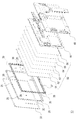
- FIG. 2 is an exploded perspective view of the liquid crystal television 10.
- the liquid crystal television 10 includes a frame-like frame 20 that is an exterior side cabinet, a front transparent protective cover 30, and a rear rear cabinet 40 as exteriors.
- a front cabinet 35, a sheet group 50, and a backlight chassis 60 are disposed inside the exteriors from the transparent protective cover 30 side.
- the frame 20 is a molded part made of a metal processed member (processing an extruded material or a drawn material). Although the detailed structure will be described later, for example, in the case of the 20 inch class, the approximate size is about 490 mm wide ⁇ about 290 mm high.
- the transparent protective cover 30 is a glass plate, for example, and protects the sheet group 50.
- the rear cabinet 40 is formed of a resin material.
- the front cabinet frame 35 is formed of a resin material in the same size and shape as the frame 20 and attached to the back side of the frame 20.
- the frame 20 is formed with a cylindrical positioning projection 25 extending in the rearward direction at a predetermined position.
- positioning boss holes 37 are provided on the front side of the front cabinet frame 35. Further, at the four corners on the front surface side (the frame 20 side) of the front cabinet frame 35, fitting convex portions 39 that fit into bending hole portions 83 of the frame 20 described later are provided.
- a liquid crystal panel 51 In the sheet group 50, a liquid crystal panel 51, a Df sheet 52, a lens sheet 53, a light guide plate 54, a diffusion sheet 55, and a reflection plate 56 are arranged in a laminated form from the front side.
- the backlight chassis 60 is obtained by processing a metal plate into a predetermined shape, and includes a light source (for example, LED edge light), a video drive circuit, a battery, and the like (not shown).
- a light source for example, LED edge light
- a video drive circuit for example, a battery, and the like (not shown).
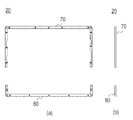
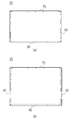
- FIG. 3 and 4 show a plan view (FIG. 3 (a), FIG. 4 (a)) and a side view (FIG. 3 (b), FIG. 4 (b)) of the frame 20.
- FIG. FIG. 4 shows the frame 20 in a separated state.
- FIG. 5 is a rear view of the frame 20.
- the frame 20 is composed of a first frame 70 and a second frame 80 and is coupled by a coupling member 90.
- the upper first frame 70 and the lower second frame 80 are integrally coupled by the coupling member 90 at two locations on both side surfaces of the back surface portion.
- the first frame 70 and the second frame 80 are each formed from an extruded member (or a drawer member) such as an aluminum alloy or stainless steel.
- the extruded material frame 20 having a predetermined cross-sectional shape is processed to have a predetermined notch shape so that a portion corresponding to the four corners (hereinafter referred to as a corner portion) can be bent, and further, a predetermined size. It is bent at R.
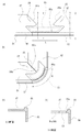
- FIG. 6 shows an enlarged perspective view of the corner. Since the four corners have the same shape, the bent portion of the first frame 70 and the bent portion of the second frame 80 have substantially the same shape, and the following mainly represents the second frame 80 unless otherwise specified. explain.
- FIG. 7A shows a state before the corner portion is bent
- FIG. 7B shows a state of the corner portion after the processing.
- FIG. 7C is a sectional view taken along line XX of FIG. 7A
- FIG. 7D is a sectional view taken along line YY of FIG. 7A.
- the second frame 80 is first cut into a predetermined length of an extruded material of an aluminum alloy according to the size of the liquid crystal television 10.
- the cross-sectional shape is a protective cover placement portion 87 (the front portion of the base portion 81 and the side portion 82) where the transparent protective cover 30 is placed, and an outer periphery that protrudes one step higher than the protective cover placement portion 87 at the outer peripheral portion.
- the projection 86 includes a frame side surface 88 exposed as a side surface of the liquid crystal television 10. In other words, it is not an L-shape but a T-shape (a state in which it is laid down).
- the outer peripheral projection 86 is set according to the thickness of the transparent protective cover 30 and has a height of about 1.5 mm, for example.
- the second frame 80 is formed with a shape corresponding to a corner portion (a bent hole portion 83 and first and second restricting convex portions 84 and 85 described later) and a frame-side screw hole 99.
- the bending hole 83 has a substantially inverted trapezoidal shape.
- the height of the inverted trapezoid (the distance from the light leakage preventing meat portion 88a to the first and second restricting convex portions 84, 85) is about 10 mm.
- the length L of the lower side of the inverted trapezoid is set to be the same as (or slightly longer than) the length corresponding to R of the bent portion. This is to enable a proper and easy bending process.
- the transparent protective cover 30 when the transparent protective cover 30 is disposed in the cut-out bent hole portion 83, the light leakage preventing meat portion 88a left unprocessed by a predetermined size is provided to prevent light leakage inside the liquid crystal television 10. Is provided. After the second frame 80 is bent, the left side portion of the bending hole portion 83 becomes the bottom front surface portion 81 extending left and right, and the right side portion becomes the side portion 82 extending vertically.
- a first restricting convex portion 84 and a second restricting convex portion 85 are formed in the inner portion of the bent hole portion 83 (the upper portion in FIG. 7A). Specifically, the first restricting convex portion 84 extends from the bottom front surface portion 81 toward the bending hole portion 83. Similarly, the second restricting convex portion 85 extends from the side portion 82 toward the bending hole portion 83. At this time, the restricting surface 84a that is the end of the first restricting convex portion 84 has an angle of 45 degrees from the upper left to the lower right. The restriction surface 85a that is the end of the second restriction convex portion 85 has an angle of 45 degrees obliquely from the upper right to the lower left.
- the tip of the V-cut shape is a large hole (bending hole 83).
- the front cabinet frame 35 has a convex fitting size that is substantially the same as the shape of the bending hole 83 at the position corresponding to the bending hole 83, that is, at the four corners on the front side.
- a convex portion 39 is formed.
- the height of the fitting convex portion 39 is set to be lower than the upper surface of the frame 20 (the surface of the protective cover placement portion 87) when fitted. This configuration also ensures positioning and prevention of misalignment.
- FIG. 8 and FIG. 9 show the details of the assembled part of the first frame 70 and the second frame 80.
- the first frame 70 and the second frame 80 are coupled by a coupling member 90 at their back portions.
- a total of four frame side screw holes 79a, 79b, 89a, 89b are formed in the side part 72 of the first frame 70 and the side part 82 of the second frame 80, respectively.
- frame side screw holes 79a and 79b are not distinguished from each other, they are simply referred to as frame side screw holes 79.
- the two frame side screw holes 89a and 89b are not distinguished, they are simply referred to as frame side screw holes 89.
- the frame side screw holes 79a, 79b, 89a, 89b have a partially conical shape corresponding to the countersunk head screw 99.
- the coupling member 90 is, for example, a material obtained by processing an aluminum alloy plate or the like, and has a total of four coupling member side screw holes 92a and 92b at positions corresponding to the frame side screw holes 79 and 89 (unless particularly distinguished from each other). Simply referred to as a connecting member side screw hole 92).
- the inner two connecting member side screw holes 92a are set with an offset ⁇ X so as to be slightly closer to the frame side screw holes 79a and 89a in the vertical direction in the figure. Yes.
- the offset ⁇ X is, for example, about 0.05 mm to 0.10 mm. Further, as shown in FIG.
- the frame side screw holes 79 (79a, 79b), 89 (89a, 89b) and the coupling member side screw holes 92 are also provided with a predetermined offset in the width direction.
- ⁇ Y is set, and a force acts in a direction in which the coupling member 90 is pressed against the side portion 82 of the second frame 80.
- the first frame 70 and the second frame 80 are fastened by the coupling member 90, the first frame 70 and the second frame 80 are brought closer to each other by the offsets ⁇ X and ⁇ Y.
- the force acts on. Therefore, it is possible to correct the state in which the end portions of the first frame 70 and the second frame 80 are bent in the opening direction by the restoring force, and to maintain the assembled state of the frame 20 appropriately. Can do.
- a predetermined R can be easily generated at the bent portion of the frame 20 and can be accurately adjusted to a predetermined bending angle.
- the transparent protective cover 30 is attached directly on the frame 20, there is no gap between the transparent protective cover 30 and the frame 20 so that the inside can be visually recognized by the thick portion (light leakage prevention meat portion 88a) of the corner portion,
- the parts under the frame 20 are not visible. That is, it can be blinded without using additional components other than the frame 20.
- the frame 20 is created, the structure is such that two substantially symmetrical members are fixed, so that the force applied to the four corners is equalized. As a result, the deformation of the product can be reduced.
- the accuracy of the square frame can be ensured by adjusting the connecting member 90 of the connecting portion.
- FIG. 10 shows a plan view of the corner portion of the second frame 80 according to the modification. Specifically, FIG. 10A shows a state before the corner portion is bent, and FIG. ) Shows the state of the corner after processing. As shown in the figure, a fitting convex portion 84 b is formed on the regulating surface 84 a of the first regulating convex portion 84. Further, a fitting recess 85 b is formed on the restriction surface 85 a of the second restriction convex portion 85. When bent, the fitting convex portion 84b and the fitting concave portion 85b are configured to just fit.
- a locking piece is formed on the fitting convex portion 84b, and a locking concave portion that locks the locking piece is formed on the fitting concave portion 85b.
- the locking piece has a semicircular convex shape in plan view
- the locking concave portion has a semicircular concave shape.
- the first restricting convex portion 84 and the second restricting convex portion 85 have a function of locking when the first restricting convex portion 84 and the second restricting convex portion 85 are bent. It is possible to add a force (a restoring force) against a restoring force acting on each bent portion of the frame 80. As a result, the structure that resists the restoring force by the coupling member 90 can be reduced, and the degree of freedom in component placement is improved. Moreover, the precision of bending process of the 2nd flame
- the structure which does not have a locking piece or a locking recessed part may be employ
- the fitting convex part 84c and the fitting recessed part 85c are made into semicircle shape.
- the fitting convex part 84d and the fitting recessed part 85d are made into the rectangular shape.
- a plurality of rectangular fitting convex portions 84e and fitting concave portions 85e are arranged. Since there is no locking structure, the restoring force is smaller than the structure shown in FIG. 10, but a constant restoring force can be obtained by the frictional force. Moreover, if it is these structures, the force fitted at the time of a bending process can be made small.
- FIG. 12 is a perspective view of a modified example of the corner portion of the second frame 80, showing a modified example of the fitting structure of the bent hole 83 and the fitting convex portion 39 shown in FIG.
- two columnar positioning convex portions 39a and 39b are formed instead of the fitting convex portion 39.
- These positioning protrusions 39a and 39b are inserted in the vicinity of both sides of the bending hole 83. Therefore, the central part of the bending hole 83 is vacant.
- frame 20 (2nd frame 80) is inserted in the vacant part.
- the two positioning projections 39a and 39b of the front cabinet frame 35 are inserted into the bending hole 83 from the back side, and the positioning projection 31 of the transparent protective cover 30 is inserted from the front side.
- the effect of positioning of the transparent protective cover 30 and a shift prevention is also acquired.
Abstract
精度を確保したフレーム構造を有する薄型表示装置に関する技術を提供する。 曲げ穴部(83)の内側部分には、第1及び第2の規制用凸部(84、85)が形成される。第1の規制用凸部(84)の端部である規制面(84a)は、左上から右下に斜め45度の角度を呈している。第2の規制用凸部(85)の端部である規制面(85a)は、右上から左下に斜め45度の角度を呈している。折り曲げ加工されたときに、第1の規制用凸部(84)の規制面(84a)と第2の規制用突部(85)の規制面(85a)が当接する。
Description
本発明は、薄型表示装置に係り、例えば、液晶テレビ等やタブレット型表示装置に好適な薄型表示装置に関する。
近年、テレビの薄型軽量化が進んでおり、20型等の比較的軽量のものは可搬型のものも複数発売されている。可搬型の場合は、据え置き型に比べて、より薄型軽量が求められており、さらにスタイリッシュな形状が求められることから、狭額縁も求められる。
例えば、薄型表示装置用外装キャビネットを高精度で簡単に成形加工することができる成形加工方法を提供する技術がある(特許文献1参照)。この技術では、外装キャビネットの枠部及びカバー部に対応する部分が長手方向に沿って形成された金属製の加工材を所定の長さに切断する。そして、切断された加工材のカバー部に対応する部分の複数個所を切断してV字状の切欠きを形成する。切欠きに対向する個所を曲げ加工して枠状の外装キャビネットを成形する。
ところで、一般に、液晶テレビにおいては、ベゼルと称する金属製の四角のフレームによってパネル、光学シート等の光学部材を包み込む形で固定し、それをキャビネットで覆う構造である場合が多い。しかしながら、上記のように薄型、軽量、狭額縁を実現するためには、上記のようなベゼルのフレーム構造によらない構造が求められていた。
また、可搬型の比較的小型のTVにおいてはデザイン上、製品の4隅の角をある程度丸みを帯びた形状とする場合もあり、その際、フレームの折り曲げ角度を正確に規定しつつ、角の丸みを確保する工夫が必要であった。また、可搬型のTVにおいては、パネルの破損防止のために表面に保護用カバーをつける場合があり、保護カバーをフレームに取り付ける際、隙間を防ぐ工夫が求められていた。
特許文献1に開示の技術では、押出し成型品に切れ込みを入れ、テレビのフレームを作成することができる。しかし、折り曲げ部に所定の曲げRを作りつつ、折り曲げ角度を確保することが出来ないという課題があり、別の技術が求められていた。
本発明は以上のような状況に鑑みなされたものであって、上記課題を解決する技術を提供することを目的とする。
本発明に係る薄型表示装置は、金属製のフレーム枠と、前記フレーム枠の前面側に配置される保護パネルと、前記フレーム枠の背面側に配置されるリアキャビネットとを備える薄型表示装置であって、前記フレーム枠は、曲げ加工された複数のフレーム部材を結合して構成されており、前記曲げ加工される部分には、曲げ加工用の穴部と、加工前は離間し加工時には互いが当接することで前記曲げ加工の量を所定に規制する二つの規制手段とが形成されている。
また、前記複数のフレーム部材を結合して前記フレーム枠を成す結合部材を備えてもよい。
また、前記結合部材と前記フレーム部材とは、複数点においてビス固定されており、それら対応するビス穴にはオフセットが設定されてもよい。
また、前記複数のフレーム部材を結合して前記フレーム枠を成す結合部材を備えてもよい。
また、前記結合部材と前記フレーム部材とは、複数点においてビス固定されており、それら対応するビス穴にはオフセットが設定されてもよい。
本発明によれば、精度を確保したフレーム構造を有する薄型表示装置に関する技術を提供することができる。
次に、本発明を実施するための形態を、図面を参照して具体的に説明する。以下では、薄型表示装置として、液晶テレビについて例示するが、当然に、液晶モニタや携帯端末(携帯電話やタブレット型表示装置)についても適用することができる。
本実施形態のポイントの概要は以下の通りである。
(1) 金属製の加工材のカバー部に対応する部分の複数個所を切り欠く。切り欠かれた部分の枠部に対応する部分を曲げ加工し、曲げ加工された加工材を用いて枠状の外装キャビネット(フレーム)を成形する。切り欠け部分において、曲げに近い部分は広い穴状とし、曲げから遠い部分は折り曲げ完了時に密着し、折り曲げ角度を正確に規制する形状である。
(2) 曲げに近い部分に段差のある所定の肉が盛ってある。
(3) 1つの部材について折り曲げ部分は2つである。
(4) 部材の結合は結合部材を介して行う。
(1) 金属製の加工材のカバー部に対応する部分の複数個所を切り欠く。切り欠かれた部分の枠部に対応する部分を曲げ加工し、曲げ加工された加工材を用いて枠状の外装キャビネット(フレーム)を成形する。切り欠け部分において、曲げに近い部分は広い穴状とし、曲げから遠い部分は折り曲げ完了時に密着し、折り曲げ角度を正確に規制する形状である。
(2) 曲げに近い部分に段差のある所定の肉が盛ってある。
(3) 1つの部材について折り曲げ部分は2つである。
(4) 部材の結合は結合部材を介して行う。
図1は、本実施形態に係る液晶テレビ10の外観を示す図である。また、図2は、液晶テレビ10の分解斜視図である。液晶テレビ10は、外装として外装側面キャビネットである枠状のフレーム20と、前側の透明保護カバー30と、後側のリアキャビネット40を備えている。そして、それら外装の内部には、透明保護カバー30側から、フロントキャビネット35、シート群50、バックライトシャーシ60が配置されている。
フレーム20は、金属製の加工部材(押し出し材または引き抜き材を加工)による成形部品である。詳細な構造については後述するが、例えば20インチクラスであれば、概略大きさは幅約490mm×高さ約290mmである。
透明保護カバー30は、例えばガラス板であって、シート群50を保護する。リアキャビネット40は、樹脂材で成形されている。
フロントキャビネット枠35は、フレーム20と略同様の大きさ及び形状に樹脂材で成形され、フレーム20の背面側に取り付けられる。なお、フレーム20には、所定位置に円柱状の位置決め用突部25が後ろ方向に延びて形成されている。位置決め用突部25に対応して、フロントキャビネット枠35の前面側には、位置決め用ボス穴37が設けられている。さらに、フロントキャビネット枠35の前面側(フレーム20側)の四隅には、後述するフレーム20の曲げ穴部83と嵌合する嵌合用凸部39が設けられている。
シート群50は、前方側から液晶パネル51、Dfシート52、レンズシート53、導光板54、拡散シート55、反射板56が積層状に配置されている。
バックライトシャーシ60は、金属の板状体を所定形状に加工したものであって、図示しない光源(例えばLEDエッジライト)や、映像駆動回路、バッテリ等が配置されている。
つづいて、本実施形態に特徴的であるフレーム20について詳細に説明する。
図3及び図4は、フレーム20の平面図(図3(a)、図4(a))及び側面図(図3(b)、図4(b))を示している。なお、図4は、フレーム20を分離した状態で示している。また、図5は、フレーム20の背面図を示している。
図3及び図4は、フレーム20の平面図(図3(a)、図4(a))及び側面図(図3(b)、図4(b))を示している。なお、図4は、フレーム20を分離した状態で示している。また、図5は、フレーム20の背面図を示している。
図示にように、フレーム20は、第1のフレーム70と第2のフレーム80とから構成され、結合部材90によって結合されている。具体的は、上側の第1のフレーム70と下側の第2のフレーム80とが、背面部分の両側面の2カ所で、結合部材90によって一体に結合されている。
第1のフレーム70及び第2のフレーム80は、それぞれ、アルミニウム合金やステンレス等の押し出し部材(引き出し部材でもよい)から成形されている。具体的には、所定断面形状の押し出し材のフレーム20を、四隅に対応する部分(以下、コーナー部という)を折り曲げ可能にするために所定の切り欠き形状の加工を施し、さらに所定大きさのRにて折り曲げ加工を施している。
図6にコーナー部の拡大斜視図を示す。四隅とも同一形状であるので、第1のフレーム70の曲げ部分及び第2のフレーム80の曲げ部分は実質同一形状であり、以下では特に断りがない限り主に第2のフレーム80に関して代表して説明する。また、図7(a)にコーナー部の折り曲げ加工前の状態を示し、図7(b)に加工後のコーナー部の状態を示している。また、図7(c)は図7(a)のX-X断面図、図7(d)は図7(a)のY-Y断面図を示している。
第2のフレーム80は、まず、アルミニウム合金の押し出し材を液晶テレビ10の大きさに応じて所定長にカットされる。断面形状は、透明保護カバー30が配置される保護カバー配置部87(底辺部81、側辺部82の前面部分)と、外周部分において保護カバー配置部87より一段高く突状となっている外周突部86と、液晶テレビ10の側面として露出するフレーム側面部88とから構成されている。言い換えると、L字状ではなくT字状(横に倒した状態)となっている。外周突部86は、透明保護カバー30の厚さに応じて設定され、例えば、約1.5mmの高さである。
つづいて、第2のフレーム80には、コーナー部に対応する形状(後述の曲げ穴部83や第1及び第2の規制用凸部84、85)及びフレーム側ビス穴99が形成される。図7(a)の曲げ加工前の状態では、曲げ穴部83は略逆台形の形状を呈している。逆台形の高さ(漏光防止肉部88aから第1及び第2の規制用凸部84、85、までの距離)は、10mm前後である。さらに、逆台形の下辺の長さLは、曲げ部のRに対応した長さと同じ(または若干長く)に設定されている。これは、適正かつ容易に曲げ加工を可能とするためである。
また、切り欠き加工された曲げ穴部83において、透明保護カバー30が配置されたときに、液晶テレビ10内部の光漏れ防止のために、所定寸法だけ未加工に残された漏光防止肉部88aが設けられている。なお、第2のフレーム80が曲げ加工された後に、曲げ穴部83の左側部分は左右に延びる底前面部81となり、右側部分は上下に延びる側辺部82となる。
さらに、曲げ穴部83の内側部分(図7(a)の上側部分)には、第1の規制用凸部84と第2の規制用凸部85が形成される。具体的には、第1の規制用凸部84は、底前面部81から曲げ穴部83へ向けて延出する。同様に、第2の規制用凸部85は側辺部82から曲げ穴部83へ向けて延出する。このとき、第1の規制用凸部84の端部である規制面84aは、左上から右下に斜め45度の角度を呈している。第2の規制用凸部85の端部である規制面85aは、右上から左下に斜め45度の角度を呈している。つまり、Vカットの形状の先端分が大きな穴(曲げ穴部83)となっている。そして、フロントキャビネット枠35には、曲げ穴部83に対応する位置に、つまり、前面側の四隅に、曲げ穴部83の形状と略同一で、ちょうど嵌合する大きさの凸状の嵌合用凸部39が形成されている。嵌合用凸部39の高さは、嵌合した際に、フレーム20の上面(保護カバー配置部87の面)より低くなるように設定されている。この構成によっても、位置決め及びズレ防止が確実になされる。
そして、図7(b)に示すように、折り曲げ加工されたときに、第1の規制用凸部84の規制面84aと第2の規制用突部85の規制面85aが当接する。この当接によって、底前面部81と側辺部82とは直角になり、それ以上、曲がることがない。つまり、曲げ加工を精度良く行うことができ、第1のフレーム70と第2のフレーム80とを組み付けた後も、歪みが生じることがない。
図8及び図9に第1のフレーム70と第2のフレーム80との組み付け部分の詳細を状態を示す。第1のフレーム70と第2のフレーム80は、それらの背面部分において、結合部材90によって結合される。第1のフレーム70の側辺部72と第2のフレーム80の側辺部82には、それぞれ二つのフレーム側ビス穴79a、79b、89a、89bが計4個形成されている。なお、二つのフレーム側ビス穴79a、79bを区別しないときは単にフレーム側ビス穴79と表記する。同様に、二つのフレーム側ビス穴89a、89bを区別しないときは単にフレーム側ビス穴89と表記する。フレーム側ビス穴79a、79b、89a、89bは、皿頭ビス99に対応した一部円錐形状となっている。
結合部材90は、例えば、アルミニウム合金の板材等を加工した物であって、フレーム側ビス穴79、89に対応する位置に計4個の結合部材側ビス穴92a、92b(特に区別しない場合は単に結合部材側ビス穴92と表記する)が形成されている。ここで、図9(a)に示すように、内側二つの結合部材側ビス穴92aは、フレーム側ビス穴79a、89aに対して、図示上下方向にそれぞれ若干近づくようにオフセットΔXが設定されている。オフセットΔXは、例えば、0.05mmから0.10mm程度である。また、図9(b)に示すように、幅方向に対しても、フレーム側ビス穴79(79a、79b)、89(89a、89b)と結合部材側ビス穴92とには、所定のオフセットΔYが設定され、結合部材90が第2のフレーム80の側辺部82へ押しつけられる方向に、力が作用する。
したがって、結合部材90によって第1のフレーム70と第2のフレーム80とが締結されると、上記のオフセットΔX、ΔYによって、第1のフレーム70と第2のフレーム80とには相互に近づく方向に力が作用する。したがって、第1のフレーム70や第2のフレーム80の各折り曲げ各部分に、復元力により端部が開く方向に作用する状態を是正することができ、フレーム20の組み付け状態を適正に維持することができる。
以上、本実施形態の効果の概要をまとめると、以下の通りである。
フレーム20の折り曲げ部分に所定のRを容易に生成でき、かつ、所定の折り曲げ角度に正確に合わせることができる。また、フレーム20上に直接透明保護カバー30を取り付ける際、コーナー部分の厚盛部分(漏光防止肉部88a)によって透明保護カバー30とフレーム20の間に、内部を視認できるような隙間が無くなり、フレーム20の下の部品が見えなくなる。つまり、フレーム20以外の追加部品を用いることなく目隠しができる。フレーム20を作成する際、ほぼ対称形状の2つの部材を固定する構造となるので、四隅への力の加わり方が均等となる。その結果、製品の変形を軽減できる。繋ぎ部の結合部材90の調整によって四角枠の精度を確保できる。
フレーム20の折り曲げ部分に所定のRを容易に生成でき、かつ、所定の折り曲げ角度に正確に合わせることができる。また、フレーム20上に直接透明保護カバー30を取り付ける際、コーナー部分の厚盛部分(漏光防止肉部88a)によって透明保護カバー30とフレーム20の間に、内部を視認できるような隙間が無くなり、フレーム20の下の部品が見えなくなる。つまり、フレーム20以外の追加部品を用いることなく目隠しができる。フレーム20を作成する際、ほぼ対称形状の2つの部材を固定する構造となるので、四隅への力の加わり方が均等となる。その結果、製品の変形を軽減できる。繋ぎ部の結合部材90の調整によって四角枠の精度を確保できる。
以上、本発明を実施形態をもとに説明した。この実施形態は例示であり、それらの各構成要素の組み合わせにいろいろな変形例が可能なこと、またそうした変形例も本発明の範囲にあることは当業者に理解されるところである。
図10は、変形例に係る第2のフレーム80のコーナー部の平面図を示しており、具体的には、図10(a)にコーナー部の折り曲げ加工前の状態を示し、図10(b)に加工後のコーナー部の状態を示している。図示のように、第1の規制用凸部84の規制面84aに嵌合凸部84bが形成されている。また、第2の規制用凸部85の規制面85aには嵌合凹部85bが形成されている。折り曲げ加工されたときに、嵌合凸部84bと嵌合凹部85bとが、ちょうど嵌合するように構成されている。さらに、嵌合状態を維持するために、嵌合凸部84bには係止片が形成され、嵌合凹部85bにはその係止片と係止する係止凹部が形成されている。ここでは、図示のように、係止片は平面視で半円凸状であり、係止凹部は半円凹状である。
このように、第1の規制用凸部84と第2の規制用凸部85とが、折り曲げ加工されたときに係止する機能を有する構成とすることで、第1のフレーム70や第2のフレーム80の各折り曲げ各部分に作用する復元力に抗する力(対復元力)を追加できる。その結果、結合部材90による上記復元力に抗する構造を小さくすることができ、部品の配置における自由度が向上する。また、嵌合凸部84b及び嵌合凹部85bの嵌合によって、第2のフレーム80等の折り曲げ加工の精度を向上させることができる。また、嵌合によって、第2のフレーム80へ外力が加わったときに、加工形状を適正に維持することができる。
なお、図11に示すように、係止片や係止凹部を有していない構造が採用されてもよい。図11(a)では、嵌合凸部84cと嵌合凹部85cは半円状としている。図11(b)では、嵌合凸部84dと嵌合凹部85dは矩形状としている。図11(c)では、矩形形状の嵌合凸部84eと嵌合凹部85eを複数配置した形状としている。係止構造はないことから、図10で示した構造よりは対復元力が小さいが、摩擦力によって一定の対復元力が得られる。また、これらの構造であれば、折り曲げ加工時に嵌合させる力を小さくできる。
図12は、第2のフレーム80のコーナー部の変形例の斜視図であり、図6に示した曲げ穴部83と嵌合用凸部39の嵌合構造の変形例を示している。具体的には、フロントキャビネット枠35には、嵌合用凸部39の代わりに、二つの円柱状の位置決め凸部39a、39bが形成されている。これらの位置決め凸部39a、39bは、曲げ穴部83の両サイド近傍部分に挿入される。そのため、曲げ穴部83の中央部分が空くことになる。そしてその空いた部分には、フレーム20(第2のフレーム80)の前面側に配置される透明保護カバー30のコーナー背面部分に形成された位置決め凸部31が挿入される。つまり、曲げ穴部83には、背面側からフロントキャビネット枠35の二つの位置決め凸部39a、39bが、前面側から透明保護カバー30の位置決め凸部31が、それぞれ挿入される。このような構成とすることで、透明保護カバー30の位置決め及びズレ防止の効果も得られる。
10 液晶テレビ
20 フレーム
25 位置決め用突部25
30 透明保護カバー
31 位置決め凸部
35 フロントキャビネット枠
37 位置決め用ボス穴37
39 嵌合用凸部
39a、39b 位置決め凸部
40 リアキャビネット
50 シート群
51 液晶パネル
52 Dfシート
53 レンズシート
54 導光板
55 拡散シート
56 反射板
60 バックライトシャーシ
70 第1のフレーム
79、89、79a、79b、89a、89b フレーム側ビス穴
80 第2のフレーム
81 底前面部
82 側辺部
83 曲げ穴部
84 第1の規制用凸部
84a 規制面
84b~84e 嵌合凸部
85 第2の規制用凸部
85a 規制面
85b 係止凹部
85b~85e 嵌合凹部
86 外周突部
87 保護カバー配置部
88 フレーム側面部
88a 漏光防止肉部
90 結合部材
92、92a、92b 結合部材側ビス穴
99 皿頭ビス
Claims (3)
- 金属製のフレーム枠と、前記フレーム枠の前面側に配置される保護パネルと、前記フレーム枠の背面側に配置されるリアキャビネットとを備える薄型表示装置であって、
前記フレーム枠は、曲げ加工された複数のフレーム部材を結合して構成されており、
前記曲げ加工される部分には、曲げ加工用の穴部と、加工前は離間し加工時には互いが当接することで前記曲げ加工の量を所定に規制する二つの規制手段とが形成されている
ことを特徴とする薄型表示装置。 - 前記複数のフレーム部材を結合して前記フレーム枠を成す結合部材を備えることを特徴とする請求項1に記載の薄型表示装置。
- 前記結合部材と前記フレーム部材とは、複数点においてビス固定されており、それら対応するビス穴にはオフセットが設定されていることを特徴とする請求項2に記載の薄型表示装置。
Priority Applications (5)
| Application Number | Priority Date | Filing Date | Title |
|---|---|---|---|
| US14/113,985 US8773609B2 (en) | 2011-04-27 | 2012-04-19 | Thin display device |
| CN201280020415.4A CN103503052B (zh) | 2011-04-27 | 2012-04-19 | 薄型显示装置 |
| EP12775995.9A EP2704129B1 (en) | 2011-04-27 | 2012-04-19 | Thin display device |
| US14/296,132 US8964145B2 (en) | 2011-04-27 | 2014-06-04 | Thin display device |
| US14/585,026 US9436029B2 (en) | 2011-04-27 | 2014-12-29 | Thin display device |
Applications Claiming Priority (2)
| Application Number | Priority Date | Filing Date | Title |
|---|---|---|---|
| JP2011-099034 | 2011-04-27 | ||
| JP2011099034A JP5149419B2 (ja) | 2011-04-27 | 2011-04-27 | 薄型表示装置 |
Related Child Applications (2)
| Application Number | Title | Priority Date | Filing Date |
|---|---|---|---|
| US14/113,985 A-371-Of-International US8773609B2 (en) | 2011-04-27 | 2012-04-19 | Thin display device |
| US14/296,132 Division US8964145B2 (en) | 2011-04-27 | 2014-06-04 | Thin display device |
Publications (1)
| Publication Number | Publication Date |
|---|---|
| WO2012147603A1 true WO2012147603A1 (ja) | 2012-11-01 |
Family
ID=47072124
Family Applications (1)
| Application Number | Title | Priority Date | Filing Date |
|---|---|---|---|
| PCT/JP2012/060557 WO2012147603A1 (ja) | 2011-04-27 | 2012-04-19 | 薄型表示装置 |
Country Status (5)
| Country | Link |
|---|---|
| US (3) | US8773609B2 (ja) |
| EP (1) | EP2704129B1 (ja) |
| JP (1) | JP5149419B2 (ja) |
| CN (2) | CN103503052B (ja) |
| WO (1) | WO2012147603A1 (ja) |
Cited By (1)
| Publication number | Priority date | Publication date | Assignee | Title |
|---|---|---|---|---|
| CN105280095A (zh) * | 2014-07-15 | 2016-01-27 | 群创光电股份有限公司 | 显示装置 |
Families Citing this family (14)
| Publication number | Priority date | Publication date | Assignee | Title |
|---|---|---|---|---|
| JP5432399B2 (ja) * | 2012-06-22 | 2014-03-05 | シャープ株式会社 | 表示装置及びテレビジョン受信機 |
| JP5567174B2 (ja) * | 2012-06-22 | 2014-08-06 | シャープ株式会社 | 表示装置及びテレビジョン受信機 |
| JP5449599B2 (ja) * | 2013-05-29 | 2014-03-19 | シャープ株式会社 | 薄型表示装置 |
| JP2015103676A (ja) * | 2013-11-25 | 2015-06-04 | 株式会社ノーリツ | パワーコンディショナ |
| JP2014063195A (ja) * | 2013-12-20 | 2014-04-10 | Sharp Corp | 薄型表示装置 |
| KR102264382B1 (ko) * | 2014-12-04 | 2021-06-14 | 엘지디스플레이 주식회사 | 가이드 패널 및 이를 구비한 액정표시장치 |
| JP6215867B2 (ja) * | 2015-05-22 | 2017-10-18 | ミネベアミツミ株式会社 | 面状照明装置 |
| KR102579620B1 (ko) | 2016-01-05 | 2023-09-15 | 엘지전자 주식회사 | 디스플레이 디바이스 |
| US11092831B2 (en) * | 2017-02-09 | 2021-08-17 | Panasonic Intellectual Property Management Co., Ltd. | Image display apparatus |
| CN107238959B (zh) * | 2017-07-10 | 2020-09-04 | 深圳市华星光电技术有限公司 | 一种液晶显示器的框架及其制造方法 |
| EP3477365B1 (en) * | 2017-10-24 | 2020-12-16 | Barco N.V. | Display tile with increased display area |
| EP3543821B1 (de) | 2018-03-22 | 2020-11-18 | Siemens Aktiengesellschaft | Rahmen für ein ein- und ausgabegerät und verfahren zum herstellen eines rahmens |
| CN109257554B (zh) * | 2018-10-30 | 2021-06-15 | 泰洋光电(惠州)有限公司 | 一种液晶电视机一体式金属背板拼接结构 |
| CN109254440A (zh) * | 2018-11-16 | 2019-01-22 | 苏州品祺电子科技有限公司 | 液晶显示屏边框圆角衔接结构 |
Citations (7)
| Publication number | Priority date | Publication date | Assignee | Title |
|---|---|---|---|---|
| JPS63153679U (ja) * | 1987-03-30 | 1988-10-07 | ||
| JPH07314593A (ja) * | 1994-05-25 | 1995-12-05 | Nippon Light Metal Co Ltd | ハニカムパネル |
| JPH0957351A (ja) * | 1995-08-30 | 1997-03-04 | Enami Seiki:Kk | 金属板の曲げ構造 |
| JP2002237212A (ja) * | 2000-12-08 | 2002-08-23 | Sharp Corp | ランプホルダ及びその配置方法 |
| JP2010132306A (ja) * | 2008-12-03 | 2010-06-17 | Qc:Kk | 液体輸送用コンテナ |
| JP3161675U (ja) * | 2010-05-26 | 2010-08-05 | 株式会社 佐渡島テック | テレビの連続一体型フレーム |
| JP2010266623A (ja) | 2009-05-14 | 2010-11-25 | Eyetec Co Ltd | 外装キャビネットの成形加工方法 |
Family Cites Families (6)
| Publication number | Priority date | Publication date | Assignee | Title |
|---|---|---|---|---|
| JPS63153679A (ja) * | 1986-12-17 | 1988-06-27 | Fuji Facom Corp | 非同期縦横走査二次元画像入力方式 |
| TW545611U (en) * | 2002-01-22 | 2003-08-01 | Chi Mei Optoelectronics Corp | Liquid crystal display device and housing thereof |
| KR100955545B1 (ko) * | 2002-03-28 | 2010-04-30 | 산요덴키가부시키가이샤 | 액정 표시 장치 |
| JP4896619B2 (ja) * | 2006-08-07 | 2012-03-14 | 株式会社 日立ディスプレイズ | 表示装置 |
| WO2009008195A1 (ja) * | 2007-07-10 | 2009-01-15 | Sharp Kabushiki Kaisha | 液晶表示パネルのバックライトシャーシ |
| JP4516106B2 (ja) * | 2007-12-18 | 2010-08-04 | 東芝モバイルディスプレイ株式会社 | 平面表示装置及びその製造方法 |
-
2011
- 2011-04-27 JP JP2011099034A patent/JP5149419B2/ja not_active Expired - Fee Related
-
2012
- 2012-04-19 EP EP12775995.9A patent/EP2704129B1/en active Active
- 2012-04-19 WO PCT/JP2012/060557 patent/WO2012147603A1/ja active Application Filing
- 2012-04-19 US US14/113,985 patent/US8773609B2/en active Active
- 2012-04-19 CN CN201280020415.4A patent/CN103503052B/zh active Active
- 2012-04-19 CN CN201410843385.8A patent/CN104537953A/zh active Pending
-
2014
- 2014-06-04 US US14/296,132 patent/US8964145B2/en active Active
- 2014-12-29 US US14/585,026 patent/US9436029B2/en active Active
Patent Citations (7)
| Publication number | Priority date | Publication date | Assignee | Title |
|---|---|---|---|---|
| JPS63153679U (ja) * | 1987-03-30 | 1988-10-07 | ||
| JPH07314593A (ja) * | 1994-05-25 | 1995-12-05 | Nippon Light Metal Co Ltd | ハニカムパネル |
| JPH0957351A (ja) * | 1995-08-30 | 1997-03-04 | Enami Seiki:Kk | 金属板の曲げ構造 |
| JP2002237212A (ja) * | 2000-12-08 | 2002-08-23 | Sharp Corp | ランプホルダ及びその配置方法 |
| JP2010132306A (ja) * | 2008-12-03 | 2010-06-17 | Qc:Kk | 液体輸送用コンテナ |
| JP2010266623A (ja) | 2009-05-14 | 2010-11-25 | Eyetec Co Ltd | 外装キャビネットの成形加工方法 |
| JP3161675U (ja) * | 2010-05-26 | 2010-08-05 | 株式会社 佐渡島テック | テレビの連続一体型フレーム |
Non-Patent Citations (1)
| Title |
|---|
| See also references of EP2704129A4 * |
Cited By (1)
| Publication number | Priority date | Publication date | Assignee | Title |
|---|---|---|---|---|
| CN105280095A (zh) * | 2014-07-15 | 2016-01-27 | 群创光电股份有限公司 | 显示装置 |
Also Published As
| Publication number | Publication date |
|---|---|
| CN103503052B (zh) | 2015-01-28 |
| US20140055713A1 (en) | 2014-02-27 |
| EP2704129A1 (en) | 2014-03-05 |
| US9436029B2 (en) | 2016-09-06 |
| US8773609B2 (en) | 2014-07-08 |
| US8964145B2 (en) | 2015-02-24 |
| EP2704129B1 (en) | 2016-03-30 |
| CN103503052A (zh) | 2014-01-08 |
| US20150116632A1 (en) | 2015-04-30 |
| JP5149419B2 (ja) | 2013-02-20 |
| JP2012230279A (ja) | 2012-11-22 |
| EP2704129A4 (en) | 2014-12-31 |
| CN104537953A (zh) | 2015-04-22 |
| US20140354916A1 (en) | 2014-12-04 |
Similar Documents
| Publication | Publication Date | Title |
|---|---|---|
| JP5149419B2 (ja) | 薄型表示装置 | |
| US10423020B2 (en) | Backlight module and display apparatus | |
| JP5513568B2 (ja) | 表示装置、及びテレビジョン受信機 | |
| JP2008158432A (ja) | 液晶表示装置 | |
| US20130148381A1 (en) | Display device | |
| KR20170052760A (ko) | 표시장치 및 이의 제조 방법 | |
| US20180217314A1 (en) | Backlight module, method for assembling the same and display device | |
| JP2014063195A (ja) | 薄型表示装置 | |
| US9658390B2 (en) | Light source cover including groove and backlight assembly including the light source cover | |
| JP5449599B2 (ja) | 薄型表示装置 | |
| JP7236706B2 (ja) | 画像表示装置 | |
| KR20160067299A (ko) | 백라이트 유닛 및 이를 구비하는 액정표시장치 | |
| US9541951B2 (en) | Display and television set | |
| JP5285807B2 (ja) | 薄型表示装置 | |
| CN104696833A (zh) | 背光模块 | |
| TWM561255U (zh) | 顯示模組及顯示裝置 | |
| US9423558B2 (en) | Display apparatus and method of assembling the same | |
| US20150022752A1 (en) | Liquid crystal display assembly and electronic device | |
| CN201307200Y (zh) | 显示模块及装备显示模块的终端机 | |
| US9575344B2 (en) | Display module | |
| CN219085248U (zh) | 一种背光模组及显示装置 | |
| WO2019105303A1 (zh) | 显示组件、终端及显示组件的安装方法 | |
| US20130128536A1 (en) | Back Frame of Flat Panel Display Device and Backlight System | |
| KR102107012B1 (ko) | 백라이트 유닛 | |
| KR20130131167A (ko) | 미디어 기기 |
Legal Events
| Date | Code | Title | Description |
|---|---|---|---|
| 121 | Ep: the epo has been informed by wipo that ep was designated in this application |
Ref document number: 12775995 Country of ref document: EP Kind code of ref document: A1 |
|
| WWE | Wipo information: entry into national phase |
Ref document number: 14113985 Country of ref document: US Ref document number: 2012775995 Country of ref document: EP |
|
| NENP | Non-entry into the national phase |
Ref country code: DE |