WO2012147551A1 - 分光光度計及びそのスリット条件決定方法 - Google Patents
分光光度計及びそのスリット条件決定方法 Download PDFInfo
- Publication number
- WO2012147551A1 WO2012147551A1 PCT/JP2012/060251 JP2012060251W WO2012147551A1 WO 2012147551 A1 WO2012147551 A1 WO 2012147551A1 JP 2012060251 W JP2012060251 W JP 2012060251W WO 2012147551 A1 WO2012147551 A1 WO 2012147551A1
- Authority
- WO
- WIPO (PCT)
- Prior art keywords
- slit
- spectrum
- wavelength
- spectrophotometer
- measurement
- Prior art date
- Legal status (The legal status is an assumption and is not a legal conclusion. Google has not performed a legal analysis and makes no representation as to the accuracy of the status listed.)
- Ceased
Links
Images



Classifications
-
- G—PHYSICS
- G01—MEASURING; TESTING
- G01J—MEASUREMENT OF INTENSITY, VELOCITY, SPECTRAL CONTENT, POLARISATION, PHASE OR PULSE CHARACTERISTICS OF INFRARED, VISIBLE OR ULTRAVIOLET LIGHT; COLORIMETRY; RADIATION PYROMETRY
- G01J3/00—Spectrometry; Spectrophotometry; Monochromators; Measuring colours
- G01J3/02—Details
- G01J3/04—Slit arrangements slit adjustment
-
- G—PHYSICS
- G01—MEASURING; TESTING
- G01J—MEASUREMENT OF INTENSITY, VELOCITY, SPECTRAL CONTENT, POLARISATION, PHASE OR PULSE CHARACTERISTICS OF INFRARED, VISIBLE OR ULTRAVIOLET LIGHT; COLORIMETRY; RADIATION PYROMETRY
- G01J3/00—Spectrometry; Spectrophotometry; Monochromators; Measuring colours
- G01J3/02—Details
- G01J3/0205—Optical elements not provided otherwise, e.g. optical manifolds, diffusers, windows
- G01J3/024—Optical elements not provided otherwise, e.g. optical manifolds, diffusers, windows using means for illuminating a slit efficiently (e.g. entrance slit of a spectrometer or entrance face of fiber)
-
- G—PHYSICS
- G01—MEASURING; TESTING
- G01J—MEASUREMENT OF INTENSITY, VELOCITY, SPECTRAL CONTENT, POLARISATION, PHASE OR PULSE CHARACTERISTICS OF INFRARED, VISIBLE OR ULTRAVIOLET LIGHT; COLORIMETRY; RADIATION PYROMETRY
- G01J3/00—Spectrometry; Spectrophotometry; Monochromators; Measuring colours
- G01J3/02—Details
- G01J3/027—Control of working procedures of a spectrometer; Failure detection; Bandwidth calculation
-
- G—PHYSICS
- G01—MEASURING; TESTING
- G01J—MEASUREMENT OF INTENSITY, VELOCITY, SPECTRAL CONTENT, POLARISATION, PHASE OR PULSE CHARACTERISTICS OF INFRARED, VISIBLE OR ULTRAVIOLET LIGHT; COLORIMETRY; RADIATION PYROMETRY
- G01J3/00—Spectrometry; Spectrophotometry; Monochromators; Measuring colours
- G01J3/02—Details
- G01J3/06—Scanning arrangements arrangements for order-selection
-
- G—PHYSICS
- G01—MEASURING; TESTING
- G01J—MEASUREMENT OF INTENSITY, VELOCITY, SPECTRAL CONTENT, POLARISATION, PHASE OR PULSE CHARACTERISTICS OF INFRARED, VISIBLE OR ULTRAVIOLET LIGHT; COLORIMETRY; RADIATION PYROMETRY
- G01J3/00—Spectrometry; Spectrophotometry; Monochromators; Measuring colours
- G01J3/12—Generating the spectrum; Monochromators
- G01J3/18—Generating the spectrum; Monochromators using diffraction elements, e.g. grating
Definitions
- the present invention relates to a spectrophotometer, for example, a technique for optimizing a slit width for determining the wavelength resolution in accordance with a sample to be measured.
- a spectrophotometer is used to measure various light absorption spectra of a sample. For example, in the case where a sample having a steep spectral waveform given as a full width at half maximum (FWHM: full width at half maximum) of about 0.1 nm is set as a measurement target, the wavelength resolution of the spectrophotometer is set to 0.1 nm or less.
- FWHM full width at half maximum
- the measurer When measuring a spectrum peak of a sample whose spectrum shape is unknown with a conventional spectrophotometer, the measurer needs to select a wavelength resolution capable of detecting the true spectrum peak of the sample. In this case, the measurer measures the same sample a plurality of times with a plurality of wavelength resolutions, and determines whether or not the wavelength resolution is satisfied from the measured spectrum waveform.
- the true spectrum shape of the measurement sample cannot be determined. For this reason, even if the wavelength resolution is switched in conjunction with wavelength scanning of monochromatic light, the true spectrum of the measurement sample cannot be measured unless the wavelength resolution used is appropriate.
- the inventor of the present application can automatically select the optimum wavelength resolution (slit condition) for measurement of an unknown sample regardless of the skill and knowledge of the measurer.
- a spectrophotometer is provided.
- the present invention it is possible to automatically set the optimum wavelength resolution for the measurement of the spectrum of the sample without the measurement person individually setting the wavelength resolution.
- the spectrophotometer includes a light source 1, an incident side slit portion 2, a spectroscope 3, an emission side slit portion 5, a photodetector 7, and a control device 14.
- the light source 1 is a light source lamp that can emit light in a certain wavelength range.
- a tungsten lamp is used as the light source 1 when the wavelength band of the measurement light is visible.
- a deuterium lamp is used as the light source 1.
- the incident-side slit portion 2 is an optical component that limits the size of the light beam emitted from the light source 1 to the spectroscope 3.
- the incident side slit portion 2 is disposed on the traveling path of the light beam emitted from the light source 1.
- the spectroscope 3 is an optical component that emits only light having a specific wavelength (monochromatic light) by dispersing incident light with a diffraction grating.
- the exit slit 5 is an optical component that limits the size of the emitted monochromatic light beam.
- the wavelength resolution is determined by the size of the light beam limited at this time.
- the exit side slit portion 5 is disposed on the traveling path of monochromatic light emitted from the spectroscope 3.
- the sample 6 is disposed on the optical path downstream of the exit side slit portion 5, and the intensity of the light beam transmitted through the sample 6 (transmitted light intensity) is detected by the photodetector 7.
- the photodetector 7 a photomultiplier tube, a photodiode or the like is used.
- the detection value of the detector 7 is output to the control device 14.
- the control device 14 is a computer that controls the entire system.
- the control device 14 is connected to the incident side slit section 2, the spectroscope 3, and the output side slit section 5 through control lines, and controls these devices via the control lines. At this time, the controller 14 controls each device so as to satisfy the absorbance measurement conditions (monochromatic light wavelength and light amount (slit gap width)).
- the control device 14 acquires the transmitted light intensity I OUT from the photodetector 7 and calculates the absorbance based on the intensity value and the incident light intensity I IN from the light source 1. Absorbance is calculated as a common logarithm of the ratio (transmittance) of transmitted light intensity I OUT to incident light intensity I IN .
- the control device 14 stores the absorbance in the storage area in association with the measurement conditions used at the time of detection. In the case of the present embodiment, the control device 14 stores the absorbance spectrum in the storage area. In this embodiment, the “absorbance spectrum” is also simply referred to as “spectrum”.
- the incident side slit part 2 has the incident side slit board 9 comprised by the some slit from which a slit clearance gap differs, and the incident side slit width switching mechanism 15 which switches the slit clearance gap used at the time of a measurement.
- the switching operation of the slit gap width by the incident side slit width switching mechanism 15 is controlled by the control device 14.
- the exit side slit portion 5 includes an exit side slit plate 10 composed of a plurality of slits having different slit gap widths, and an exit side slit width switching mechanism 16 for switching the slit gap width used for measurement. .
- the switching operation of the slit gap width by the exit side slit width switching mechanism 16 is controlled by the control device 14.
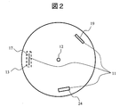
- FIG. 2 shows a structural example of the entrance side slit plate 9 and the exit side slit plate 10.
- the entrance side slit plate 9 and the exit side slit plate 10 are discs attached so as to be rotatable about the rotation shaft 12.
- three types of slits 11 are formed on the same radius and at equal intervals in the circumferential direction.
- the slit 11 is a gap formed so as to penetrate the disk in the thickness direction.
- the slit 11 is formed in a rectangular shape.
- the long side of each slit 11 is formed in parallel to the tangential direction of a circle having a certain radius. Therefore, the gap width of the slit 11 is given as the length of the short side of the slit 11.
- the slit 11 with the narrowest gap width is called the high resolution slit 17, and the slit 11 with the widest gap width is called the low resolution slit 24, and has an intermediate gap width with respect to the former.
- the slit 11 is called a medium resolution slit 19.
- the rotary shaft 12 is positioned so that all of the three slits 11 overlap the irradiation region 13 of the measurement light when the disk is driven to rotate.
- the measurement light irradiation region 13 is wide enough to cover the entire slit 11. For this reason, if the type of the slit 11 positioned at a position that blocks the measurement light irradiation region 13 is switched, the amount of light passing therethrough can be changed, and the wavelength resolution and S / N of the spectrophotometer can be changed.
- the incident side slit width switching mechanism 15 and the emission side slit width switching mechanism 16 use motors that rotationally drive the incident side slit plate 9 and the emission side slit plate 10 around the rotating shaft 12.
- the configurations of the entrance-side slit plate switching mechanism 15 and the exit-side slit plate switching mechanism 16 depend on the configurations of the entrance-side slit plate 9 and the exit-side slit plate 10. Therefore, when the incident side slit plate 9 and the emission side slit plate 10 having configurations different from those described above are used, a drive mechanism other than a motor that is a rotational drive system, such as a slide mechanism, is used.
- the spectroscope 3 includes a spectroscopic element 4 and a spectroscopic element driving mechanism 8.
- a spectroscopic element 4 for example, a diffraction grating or a prism is used.
- a drive mechanism that can change the incident angle of the measurement light that has passed through the slit 11 with respect to the spectroscopic element 4 is used as the spectroscopic element drive mechanism 8.
- the incident angle of the measurement light with respect to the spectroscopic element 4 is controlled by the control device 14 through the spectroscopic element driving mechanism 8.
- the wavelength of the monochromatic light used for the measurement light can be scanned within a certain range.
- the measurement in which the wavelength of the measurement light is scanned within a certain wavelength range within the variable wavelength range is referred to as “wavelength scanning measurement”.
- the case where the scanning range is the entire variable wavelength range is particularly referred to as “full wavelength scanning measurement”.
- the control device 14 includes a spectrum storage unit 18, a comparison determination unit 22, a slit condition storage unit 23, and a computer (not shown).
- the computer has a CPU, a RAM, a ROM, and an input / output interface.
- the comparison determination unit 22 is realized as a function of a program executed on a computer.
- control device 14 provides an automatic determination function of wavelength resolution (slit gap width) and a wavelength scanning measurement function through a program executed by a computer (not shown).
- the spectrum storage unit 18 is used to store an absorbance spectrum measured by irradiating the sample 6 with measurement light.
- the slit condition storage unit 23 stores information related to the gap width of the slit used for measurement.
- the comparison / determination unit 22 is a functional unit that compares two spectra measured by wavelength scanning with different wavelength resolutions (different slit gap widths). Specifically, the absorbance values measured for a certain wavelength are compared with each other. The comparison determination unit 22 determines the wavelength resolution to be applied to a certain wavelength range based on the comparison result. In the case of this example, when the difference in absorbance value is less than or equal to the threshold value, the two absorbances are treated as matching.
- the threshold value may be a fixed value, or may be set by the user through a GUI screen or the like.
- the comparison / determination unit 22 uses, for example, a low resolution slit 24 for a wavelength range in which a spectrum acquired using the low resolution slit 24 matches a spectrum acquired using the medium resolution slit 19. Determine the use of. For this wavelength range, an excellent S / N can be ensured.
- the comparison / determination unit 22 matches the spectrum acquired using the medium resolution slit 19 and the spectrum acquired using the high resolution slit 17. A wavelength range that does not match the wavelength range is further determined.
- the comparison / determination unit 22 determines the use of the medium resolution slit 19 for the wavelength range in which the two spectra match. With respect to this wavelength range, a measurement result in which a balance between high wavelength resolution and S / N can be obtained.
- the comparison / determination unit 22 determines the use of the high-resolution slit 17 for a wavelength range where the two spectra do not match. High wavelength resolution can be realized for this wavelength range.
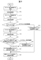
- FIG. 3 illustrates a measurement operation executed in the spectrophotometer according to the present embodiment.
- the measurement operation includes processes S11 to S21 for automatically determining an optimum wavelength resolution for each wavelength range for a sample whose spectrum shape is unknown, and a process S22 for performing wavelength scanning measurement on the sample using the determined wavelength resolution. Consists of.
- the control device 14 controls the incident side slit portion 2 and the outgoing side slit portion 5 so that the illumination region 13 of the measurement light and the low resolution slit 24 (shown as “slit 1” in the figure) overlap each other.
- a signal is output (processing S11).
- the incident side slit width switching mechanism 15 rotationally drives the incident side slit plate 9 to position the low resolution slit 24 in the illumination region 13.
- the exit side slit width switching mechanism 16 rotationally drives the exit side slit plate 10 to position the low resolution slit 24 in the illumination region 13.
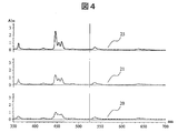
- the control device 14 controls the spectral element driving mechanism 8 of the spectroscope 3 to scan the wavelength of the monochromatic light as the measurement light within a predetermined range, and to calculate the absorbance value for each wavelength. Measurement is performed by the detector 7 (process S12). That is, using the low resolution slit 24, the absorbance of the sample is measured by scanning all wavelengths. At this time, a spectrum 20 drawn in the lower part of FIG. 4 is obtained.
- the horizontal axis of FIG. 4 is the wavelength, and the vertical axis is the spectral intensity.
- the control device 14 stores data corresponding to the spectrum 20 (data in which absorbance is associated with each wavelength in the scanning range) in the spectrum storage unit 18.
- the control device 14 proceeds to measurement preparation by the medium resolution slit 19.
- the control device 14 performs the measurement on the incident side slit portion 2 and the emission side slit portion 5 so that the illumination area 13 of the measurement light and the medium resolution slit 19 (shown as “slit 2” in the figure) overlap each other.
- a control signal is output (process S13).
- the incident side slit part 2 the incident side slit width switching mechanism 15 rotates the incident side slit plate 9 to position the medium resolution slit 19 in the illumination region 13.
- the exit side slit width switching mechanism 16 rotates the exit side slit plate 10 to position the medium resolution slit 19 in the illumination area 13.
- the control device 14 controls the spectral element driving mechanism 8 of the spectroscope 3 to scan the wavelength of the monochromatic light as the measurement light within a predetermined range, and to calculate the absorbance value for each wavelength. Measurement is performed by the detector 7 (process S14). In other words, the absorbance of the sample is scanned at all wavelengths using the medium resolution slit 19. At this time, the spectrum 21 drawn in the middle of FIG. 4 is obtained.
- the control device 14 stores data corresponding to the spectrum 21 (data in which absorbance is associated with each wavelength in the scanning range) in the spectrum storage unit 18.
- the control device 14 compares the spectrum when the low resolution slit is used with the spectrum when the medium resolution slit is used (processing S15). Specifically, the absorbances of the two spectra are compared for each wavelength.
- the comparison / determination unit 22 sets a slit to be applied to the range for the wavelength range in which the absorbances match between the two spectra as the low resolution slit 24 (processing S16).
- This setting information is stored in the slit condition storage unit 23 as a slit condition.
- the control device 14 does not perform the processing of steps S17 to S21, and the low resolution of the entrance side slit portion 2 and the exit side slit portion 5 is processed.
- the slit 24 for positioning is positioned in the irradiation region 13 of the measurement light, and the full wavelength scanning measurement for the sample 6 is executed (processing S22).
- the measurement result is stored in the spectrum storage unit 18.
- the measurement result of the full-wavelength scanning measurement using the low resolution slit 24 is stored in the spectrum storage unit 18 at the stage of processing 12. Therefore, depending on the setting of the spectrophotometer, the processing may be terminated without executing the full wavelength scanning measurement again. Even when a plurality of wavelength ranges are automatically set within the entire wavelength range, it is possible to omit the execution of wavelength scanning measurement again.
- the control device 14 stops the execution of the process 22 until the setting of the spectrum condition is confirmed for the entire wavelength range.
- control device 14 performs processing S17 to S17. S21 is executed.
- control device 14 is arranged with respect to the entrance-side slit portion 2 and the exit-side slit portion 5 so that the illumination area 13 of the measurement light and the high-resolution slit 17 (shown as “slit 3” in the figure) overlap.
- a control signal is output (process S17).
- the incident side slit part 2 the incident side slit width switching mechanism 15 rotates the incident side slit plate 9 to position the high resolution slit 17 in the illumination region 13.
- the exit slit width switching mechanism 16 rotates the exit slit plate 10 to position the high resolution slit 17 in the illumination area 13.
- the control device 14 controls the spectral element driving mechanism 8 of the spectroscope 3 to scan the wavelength of the monochromatic light as the measurement light within a predetermined range, and to calculate the absorbance value for each wavelength. Measurement is performed by the detector 7 (process S18). In other words, the absorbance of the sample is measured by wavelength scanning using the high resolution slit 17. At this time, a spectrum 25 drawn on the upper part of FIG. 4 is obtained.
- the absorbance spectrum is measured for the entire wavelength region as in the case of using the other two types of slits. Measurement using the high-resolution slit 17 may be performed only in the wavelength range determined to be.
- the control device 14 When the measurement is completed for all the wavelength ranges of the wavelength scanning range, the control device 14 (comparison / determination unit 22) performs the spectrum and the high resolution slit when using the medium resolution slit only for the wavelength range in which the mismatch is confirmed in step S15.
- the spectrum at the time of use is compared (process S19). Specifically, the absorbances of the two spectra are compared for each wavelength.
- the comparison / determination unit 22 sets a slit to be applied to the range for the wavelength range in which the absorbances match between the two spectra in the medium resolution slit 19 (processing S20). This setting information is stored in the slit condition storage unit 23 by the comparison / determination unit 22.
- the comparison / determination unit 22 sets a slit to be applied to the high resolution slit 17 for the wavelength range in which the absorbance does not match between the two spectra (processing S21). This setting information is also stored in the slit condition storage unit 23 by the comparison / determination unit 22.
- the control device 14 starts the process S22 without executing the process S21. That is, the control device 14 performs full wavelength scanning measurement on the sample 6 in accordance with the slit conditions stored in the slit condition storage unit 23 (processing S22).
- the control device 14 compares the wavelength of the monochromatic light used for measurement with the wavelength range stored in the slit condition storage unit 23, and switches the type of the slit 11 currently in use.
- the wavelength scanning is stopped at the same time, and switching of the slit 11 is instructed to the incident side slit portion 2 and the emission side slit portion 5.
- the automatic switching of the slits 11 is sequentially performed according to the slit conditions stored in the slit condition storage unit 23 during the wavelength scanning measurement.
- the measurement result is stored in the spectrum storage unit 18.
- the control device 14 starts the process S22. That is, the control device 14 performs full wavelength scanning measurement on the sample 6 in accordance with the slit conditions stored in the slit condition storage unit 23 (processing S22).
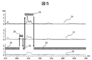
- FIG. 5 illustrates a case where the entire wavelength region of the wavelength scanning measurement is divided into five wavelength ranges, and a slit 11 of a different type from the previous wavelength range is automatically set for each wavelength range.
- FIG. 5 shows the case where the entire wavelength range is given in the range of 350 nm to 700 nm.
- the low resolution slit 24 is used for measuring the absorbance. Therefore, a measurement result excellent in S / N is obtained in this wavelength range.
- the medium resolution slit 19 is used for measuring the absorbance.
- a measurement result having an excellent balance between wavelength resolution and S / N can be obtained.
- the low resolution slit 24 is used for measuring the absorbance. In this wavelength range, a measurement result excellent in S / N can be obtained.
- the high resolution slit 17 is used for measuring the absorbance. In this wavelength range, measurement results with excellent wavelength resolution can be obtained.
- the low resolution slit 24 is used for measuring the absorbance. In this wavelength range, a measurement result excellent in S / N can be obtained.
- the measurer when the spectrophotometer according to the present embodiment is used, even when it is necessary to measure a sample with an unknown light absorption spectrum, the measurer simply sets the sample at a predetermined position on the measurement optical path. Thus, the optimum wavelength resolution corresponding to the shape of the light absorption spectrum of the sample can be automatically set for all wavelength regions. Further, the spectrophotometer according to the present embodiment can measure the absorbance of the sample by wavelength scanning based on the automatically set slit condition.
- the spectrophotometer according to the present embodiment can automate the measurement of the absorbance of a sample whose light absorption spectrum is unknown. That is, the spectrophotometer according to the present embodiment can acquire measurement results that do not depend on the skill and knowledge of the measurer.
- a slit capable of obtaining a high wavelength resolution is automatically applied to a wavelength range in which the waveform of the light absorption spectrum of the sample changes sharply, so that the light absorption spectrum waveform becomes gentle.
- a slit capable of obtaining a high S / N can be automatically applied to the wavelength range changing to.
- Example 2 In Example 1, the case where the incident side slit part 2 and the output side slit part 5 each used the incident side slit board 9 and the output side slit board 10 which have the three slits 11 from which a slit clearance gap width differs was demonstrated. However, in order to realize a spectrophotometer to which the present invention is applied, it is sufficient that the gap width of the slit is at least two. If there are at least two slit gap widths, automatic switching of the wavelength resolution within the wavelength scanning range can be realized by switching.
- FIG. 6 shows an example of the entrance side slit plate 9 and the exit side slit plate 10 in which eight types of slits are formed.
- the slit gap width increases in the clockwise direction from the position of the illumination region 13 for the measurement light.
- the wavelength scanning measurement is applied to the wavelength scanning measurement in order from the slit having the lowest wavelength resolution, and the number of times corresponding to the number of slits is measured. By repeating, the application range of the optimum wavelength resolution can be automatically set.
- both the entrance side slit plate 9 and the exit side slit plate 10 are formed in a disc shape, and a plurality of slits 11 are formed on the circumference of the disc.
- a slit plate having a configuration in which a plurality of slits 11 are arranged in a line on a straight line may be used.
- the slit gap width may be switched by sliding the slit plate in the direction in which the slits 11 are arranged.
- Example 3 In the case of Example 1, the case where the absorbance spectrum is stored in the spectrum storage unit 18 and the absorbance spectra are compared with each other in the comparison determination unit 22 has been described.
- the spectrum storage unit 18 may store a reflection spectrum or a transmitted light spectrum.
- the reflectance may be calculated by dividing the intensity of the monochromatic light reflected by the sample 6 by the intensity of the incident light and storing the reflectance in the spectrum storage unit 18.
- the transmittance is calculated by dividing the intensity of the monochromatic light transmitted through the sample 6 by the intensity of the incident light, and the transmittance is stored in the spectrum storage unit 18.
- the slit gap width to be applied that is, the wavelength resolving power, between the wavelength ranges in which the two spectrums measured for two adjacent slits are not coincident with the wavelength range in which the magnitude relation of the slit gap width is not coincident. The case of switching is described.
- full-wavelength scanning measurement may be performed using only one slit having the highest wavelength resolution ability among the slit gap widths determined for each wavelength range in this way.
- the high resolution slit 17 having the highest wavelength resolving ability may be determined as a slit to be applied to the entire wavelength region. If there are only two types of slits set for the entire wavelength region, the slit having the higher resolution ability of the two may be set as the slit for wavelength scanning measurement.
- Example 5 In the case of the above-described embodiment, the case where the spectrum waveform acquired as the measurement result is directly supplied to the comparison determination unit 22 and the wavelength range to which the different slit conditions are applied has been described. However, the wavelength range to which different slit conditions are applied may be determined by giving the waveform after signal processing of the acquired spectrum waveform to the comparison / determination unit 22.
- FIG. 7 shows an example of signal processing.
- FIG. 7 corresponds to the waveform after differentiation processing of the spectrum waveform shown in FIG.
- the wavelength range and the slit condition to be applied may be determined from the presence or absence of a peak, the shape of the peak, or the like. That is, the degree of coincidence of the slopes of the spectrum waveforms may be used as a determination criterion.
- Example 6 when the determination threshold used for determining whether the measured spectrum matches, the determination threshold used for determining the presence or absence of the peak after differentiation, the determination criterion of the peak shape, etc. are fixed to predetermined values. Is assumed. However, a configuration in which a measurer can set or adjust these threshold values and standards may be employed.
- Example 7 In the above-described embodiment, in the wavelength scanning measurement for determining the slit condition, all kinds of slits 11 arranged on the input side slit plate 9 and the output side slit plate 10 are used. Only slits having a gap width in a range may be used. As a result, the intention of the measurer can be reflected in the automatically set wavelength resolution.
- Example 8 In the above-described embodiment, the case where only one slit condition is automatically set for one sample has been described. However, as in Example 7, there are two slit conditions, a slit condition determined under conditions that limit the gap width of the slit used by the measurer, and a slit condition determined under conditions where the gap width of the slit is not limited. It may be present. Further, there may be a case where there are slit conditions individually corrected by the measurer. In such a case, in the wavelength scanning measurement for the purpose of obtaining the spectrum of the sample, one slit condition selected by the measurer from a plurality of slit conditions may be applied. By mounting such a function, a measurement result reflecting the intention of the measurer can be obtained.
- the present invention is not limited to the above-described embodiments, and includes various modifications.
- the above-described embodiments have been described in detail for easy understanding of the present invention, and are not necessarily limited to those having all the configurations described.
- a part of a certain embodiment can be replaced with the configuration of another embodiment, and the configuration of another embodiment can be added to the configuration of a certain embodiment.
- each of the above-described configurations, functions, processing units, processing means, and the like may be partly or entirely realized as, for example, an integrated circuit or other hardware.
- Each of the above-described configurations, functions, and the like may be realized by the processor interpreting and executing a program that realizes each function. That is, it may be realized as software.
- Information such as programs, tables, and files for realizing each function can be stored in a memory, a hard disk, a storage device such as an SSD (Solid State Drive), or a storage medium such as an IC card, an SD card, or a DVD.
- control lines and information lines indicate what is considered necessary for explanation, and do not represent all control lines and information lines necessary for the product. In practice, it can be considered that almost all components are connected to each other.
Landscapes
- Physics & Mathematics (AREA)
- Spectroscopy & Molecular Physics (AREA)
- General Physics & Mathematics (AREA)
- Spectrometry And Color Measurement (AREA)
Abstract
スペクトル形状が未知の試料を測定対象とする場合、測定者の経験と知識に基づいて、試料の真のスペクトルピークを検出可能な波長分解能が選択される。波長分解能の設定作業を、測定スペクトルに応じて自動的に設定できるようにする。このため、隙間幅が異なる複数のスリットを用意し、個々のスリットを通過する単色光の波長を所定の波長範囲内で走査させることにより、スリットの隙間幅別のスペクトルを測定する。この後、隙間幅が異なるスリットについて測定された複数のスペクトルの比較結果に基づいて、試料の測定に使用する少なくとも1つのスリットの隙間幅と当該スリットの隙間幅を適用する少なくとも1つの波長範囲の関係を規定するスリット条件を決定する。
Description
本発明は、分光光度計に関し、例えばその波長分解能を決定するスリット幅を測定対象の試料に応じて最適化する技術に関する。
分光光度計は、試料が有する様々な光吸収スペクトルの測定に用いられる。例えばスペクトルピークの半値全幅(FWHM: full width at half maximum)が0.1nm程度で与えられる急峻なスペクトル波形を有する試料を測定対象とする場合、分光光度計の波長分解能は0.1nm以下に設定する。
スペクトル形状が未知である試料のスペクトルピークを、従来の分光光度計で測定する場合、測定者は、試料の真のスペクトルピークを検出可能な波長分解能を選択する必要がある。この場合、測定者は、複数の波長分解能で同一試料を複数回測定し、測定されたスペクトル波形から波長分解能が満たされているか否かを判断する。
なお、試料の光吸収スペクトルの測定に必要な波長分解能が波長範囲で異なる場合、測定試料の真のスペクトル形状を判断することができない。このため、単色光の波長走査に連動して波長分解能を切り替えたとしても、使用する波長分解能が適切でなければ、測定試料の真のスペクトルを測定することはできない。
そこで、本願発明者は、当該技術的課題を鋭意検討した結果、測定者の技量や知識によらず、未知の試料の測定に最適な波長分解能(スリット条件)を自動的に選択することができる分光光度計を提供する。
本発明によれば、測定者が波長分解能を個別に設定しなくても、試料のスペクトルの測定に最適な波長分解能を自動的に設定することができる。
上述した内容以外の課題、構成及び効果は、以下の実施例の説明により明らかにされる。
以下、図面に基づいて、本発明の実施の形態を説明する。なお、本発明の実施態様は、後述する形態例に限定されるものではなく、その技術思想の範囲において、種々の変形が可能である。
[実施例1]
[分光光度計の全体構成]
実施例に係る分光光度計は、光源1、入射側スリット部2、分光器3、出射側スリット部5、光検出器7及び制御装置14で構成される。
[分光光度計の全体構成]
実施例に係る分光光度計は、光源1、入射側スリット部2、分光器3、出射側スリット部5、光検出器7及び制御装置14で構成される。
光源1には、ある波長範囲の光を射出可能な光源ランプを使用する。測定光の波長帯域が可視域の場合、光源1には、例えばタングステンランプを使用する。一方、測定光の波長帯域が紫外域の場合、光源1には、例えば重水素ランプを使用する。
入射側スリット部2は、光源1から分光器3に照射される光束の大きさを制限する光学部品である。入射側スリット部2は、光源1から放射される光束の進行路上に配置する。
分光器3は、入射された光を回折格子で分散して特定の波長を有する光(単色光)だけを射出する光学部品である。
出射側スリット部5は、射出される単色光の光束の大きさを制限する光学部品である。このとき制限される光束の大きさにより、波長分解能が決定される。出射側スリット部5は、分光器3から射出される単色光の進行路上に配置される。
出射側スリット部5の後段光路上には試料6が配置され、該試料6を透過した光束の強度(透過光強度)が光検出器7において検出される。検出器7には光電子倍増管、フォトダイオード等が用いられる。検出器7の検出値は、制御装置14に出力される。
制御装置14は、システム全体を制御するコンピュータである。制御装置14は、制御線を通じて入射側スリット部2、分光器3及び出射側スリット部5と接続されており、これらのデバイスを制御線経由で制御する。このとき、制御装置14は、吸光度の測定条件(単色光の波長及び光量(スリットの隙間幅))を満たすように、各デバイスをそれぞれ制御する。
制御装置14は、光検出器7から透過光強度IOUT を取得し、当該強度値と光源1からの入射光強度IINに基づいて吸光度を算出する。吸光度は、入射光強度IINに対する透過光強度IOUT の比(透過率)の常用対数値として算出される。制御装置14は、検出の際に使用した測定条件に吸光度を対応付けて記憶領域に格納する。本実施例の場合、制御装置14は、吸光度スペクトルを記憶領域に格納する。本実施例においては、「吸光度スペクトル」を、単に「スペクトル」ともいう。
[各部の構成]
入射側スリット部2は、スリット隙間幅が異なる複数のスリットで構成される入射側スリット板9と、測定時に使用するスリット隙間幅を切り替える入射側スリット幅切替機構15とを有している。入射側スリット幅切替機構15によるスリット隙間幅の切替動作は、制御装置14により制御される。
入射側スリット部2は、スリット隙間幅が異なる複数のスリットで構成される入射側スリット板9と、測定時に使用するスリット隙間幅を切り替える入射側スリット幅切替機構15とを有している。入射側スリット幅切替機構15によるスリット隙間幅の切替動作は、制御装置14により制御される。
同じく、出射側スリット部5は、スリット隙間幅が異なる複数のスリットで構成される出射側スリット板10と、測定に使用するスリット隙間幅を切り替える出射側スリット幅切替機構16とを有している。出射側スリット幅切替機構16によるスリット隙間幅の切替動作は、制御装置14により制御される。
図2に、入射側スリット板9と出射側スリット板10の構造例を示す。本実施例の場合、入射側スリット板9と出射側スリット板10は、回転軸12を中心に回転自在に取り付けられた円板である。本実施例の場合、3種類のスリット11が、同一半径上かつ円周方向に等間隔で形成される。ここで、スリット11は、円板をその厚み方向に貫通するように形成された隙間である。この実施例の場合、スリット11は長方形状に形成される。各スリット11の長辺は、ある半径を有する円の接線方向に対して平行に形成される。従って、スリット11の隙間幅は、スリット11の短辺の長さとして与えられる。
本実施例においては、隙間幅が最も狭いスリット11を高分解能用スリット17と呼び、隙間幅が最も広いスリット11を低分解能用スリット24と呼び、前2者に対して中間の隙間幅を有するスリット11を中分解能用スリット19と呼ぶ。回転軸12は、円板が回転駆動される際に、3つのスリット11のいずれもが測定光の照射領域13と重なるように位置決めされる。
なお、測定光の照射領域13は、いずれのスリット11に対しても、その全体を包含するだけの広がりを有している。このため、測定光の照射領域13を遮る位置に位置決めされるスリット11の種類を切り替えれば通過光量を変化させることができ、分光光度計の波長分解能及びS/Nを変更することができる。
この実施例の場合、入射側スリット幅切替機構15及び出射側スリット幅切替機構16には、回転軸12を中心に入射側スリット板9と出射側スリット板10を回転駆動するモータを使用する。なお、入射側スリット板切替機構15及び出射側スリット板切替機構16の構成は、入射側スリット板9や出射側スリット板10の構成に依存する。従って、前述とは異なる構成の入射側スリット板9及び出射側スリット板10を用いる場合には、スライド機構等、回転駆動系であるモータ以外の駆動機構が用いられる。
次に、分光器3の構成を説明する。分光器3は、分光素子4と分光素子駆動機構8により構成される。分光素子4には、例えば回折格子やプリズムを使用する。また、分光素子駆動機構8には、分光素子4が回折格子の場合、スリット11を通過した測定光の分光素子4に対する入射角を可変可能な駆動機構を使用する。測定光の分光素子4に対する入射角は、制御装置14が分光素子駆動機構8を通じて制御する。当該入射角をある角度範囲で走査することにより、測定光に使用する単色光の波長をある範囲内で走査させることができる。このように、測定光の波長を、可変可能な波長域内のうちのある波長域内で走査する測定を、本明細書では、「波長走査測定」という。なお、走査範囲が可変可能な波長域の全体である場合を特に「全波長走査測定」という。
次に、制御装置14の構成を説明する。この実施例の場合、制御装置14は、スペクトル記憶部18と、比較判定部22と、スリット条件記憶部23と、不図示のコンピュータとを有している。コンピュータは、CPUと、RAMと、ROMと、入出力インターフェースを有している。この形態例の場合、比較判定部22は、コンピュータ上で実行されるプログラムの機能として実現される。
この実施例の場合、制御装置14は、不図示のコンピュータで実行されるプログラムを通じ、波長分解能(スリットの隙間幅)の自動決定機能及び波長走査測定機能を提供する。
スペクトル記憶部18は、試料6に対する測定光の照射により測定される吸光度スペクトルの格納に使用される。スリット条件記憶部23は、測定に使用したスリットの隙間幅に関する情報を格納する。
比較判定部22は、異なる波長分解能(異なるスリット隙間幅)について波長走査測定された2つのスペクトル同士を比較する機能部である。具体的には、ある波長について測定された吸光度の値同士を比較する。比較判定部22は、比較結果に基づいて、ある波長域に適用する波長分解能を決定する。この実施例の場合、吸光度の値の違いが閾値以下のとき、2つの吸光度が一致するものとして扱う。閾値は固定値でも良いし、利用者がGUI画面等を通じて設定できるようにしても良い。
この実施例の場合、比較判定部22は、例えば低分解能用スリット24を使用して取得したスペクトルと中分解能用スリット19を使用して取得したスペクトルが一致する波長範囲について、低分解能用スリット24の使用を決定する。この波長範囲については、優れたS/Nを確保することができる。
これらの2つのスペクトルが一致しないと判定された波長範囲について、比較判定部22は、中分解能用スリット19を使用して取得したスペクトルと高分解能用スリット17を使用して取得したスペクトルが一致する波長範囲と一致しない波長範囲を更に判定する。
この場合、比較判定部22は、2つのスペクトルが一致する波長範囲について、中分解能用スリット19の使用を決定する。この波長範囲については、高波長分解能とS/Nのバランスの採れた測定結果が得られる。
一方、比較判定部22は、2つのスペクトルが一致しない波長範囲について、高分解能用スリット17の使用を決定する。この波長範囲については、高波長分解能を実現できる。
[測定動作]
図3に、本実施例に係る分光光度計において実行される測定動作について説明する。当該測定動作は、スペクトル形状が未知の試料について、波長範囲別に最適な波長分解能を自動的に決定する処理S11~S21と、決定された波長分解能を使用して試料を波長走査測定する処理S22とで構成される。
図3に、本実施例に係る分光光度計において実行される測定動作について説明する。当該測定動作は、スペクトル形状が未知の試料について、波長範囲別に最適な波長分解能を自動的に決定する処理S11~S21と、決定された波長分解能を使用して試料を波長走査測定する処理S22とで構成される。
ここでは、光吸収スペクトルの形状が未知の試料が分光光度計の所定位置に設置され、波長走査測定の自動実行が指示されたものとする。勿論、光吸収スペクトルの形状が既知である試料の測定時や波長走査測定のマニュアル実行時には、従来装置と同様の手順で測定が実行される。
まず、制御装置14は、測定光の照明領域13と低分解能用スリット24(図では「スリット1」と示す。)が重なるように、入射側スリット部2及び出射側スリット部5に対して制御信号を出力する(処理S11)。このとき、入射側スリット部2においては、入射側スリット幅切替機構15が入射側スリット板9を回転駆動し、低分解能用スリット24を照明領域13に位置決めする。また、出射側スリット部5では、出射側スリット幅切替機構16が出射側スリット板10を回転駆動し、低分解能用スリット24を照明領域13に位置決めする。
当該位置決めが終了すると、制御装置14は、分光器3の分光素子駆動機構8を制御し、測定光となる単色光の波長を所定の範囲内で走査させ、各波長についての吸光度の値を光検出器7で測定する(処理S12)。すなわち、低分解能用スリット24を用い、試料の吸光度を全波長走査測定する。このとき、図4の下段に描画するスペクトル20が得られる。
なお、図4の横軸は波長であり、縦軸はスペクトル強度である。スペクトル20の取得に伴い、制御装置14は、スペクトル20に対応するデータ(走査範囲の各波長に吸光度を対応付けたデータ)をスペクトル記憶部18に格納する。波長走査範囲の全波長域について測定が完了すると、制御装置14は、中分解能用スリット19による測定準備に移行する。
次に、制御装置14は、測定光の照明領域13と中分解能用スリット19(図では「スリット2」と示す。)が重なるように、入射側スリット部2及び出射側スリット部5に対して制御信号を出力する(処理S13)。このとき、入射側スリット部2では、入射側スリット幅切替機構15が入射側スリット板9を回転駆動し、中分解能用スリット19を照明領域13に位置決めする。また、出射側スリット部5では、出射側スリット幅切替機構16が出射側スリット板10を回転駆動し、中分解能用スリット19を照明領域13に位置決めする。
当該位置決めが終了すると、制御装置14は、分光器3の分光素子駆動機構8を制御し、測定光となる単色光の波長を所定の範囲内で走査させ、各波長についての吸光度の値を光検出器7で測定する(処理S14)。すなわち、中分解能用スリット19を用い、試料の吸光度を全波長走査測定する。このとき、図4の中段に描画するスペクトル21が得られる。
スペクトル21の取得に伴い、制御装置14は、スペクトル21に対応するデータ(走査範囲の各波長に吸光度を対応付けたデータ)をスペクトル記憶部18に格納する。
波長走査範囲の全波長域について測定が完了すると、制御装置14(比較判定部22)は、低分解能用スリット使用時のスペクトルと中分解能用スリット使用時のスペクトルを比較する(処理S15)。具体的には、波長毎に2つのスペクトルの吸光度同士を比較する。
ここで、比較判定部22は、2つのスペクトルの間で吸光度が一致した波長範囲について、当該範囲に適用するスリットを低分解能用スリット24に設定する(処理S16)。この設定情報は、スリット条件として、スリット条件記憶部23に格納される。
なお、波長走査測定を行った全波長域について2つのスペクトルが一致した場合、制御装置14は、処理S17~S21の処理を行うことなく、入射側スリット部2と出射側スリット部5の低分解能用スリット24を測定光の照射領域13に位置決めし、試料6に対する全波長走査測定を実行する(処理S22)。その測定結果は、スペクトル記憶部18に格納される。もっとも、低分解能用スリット24を使用した全波長走査測定の測定結果は、処理12の段階でスペクトル記憶部18に格納されている。従って、分光光度計の設定によっては、再度の全波長走査測定を実行することなく、処理を終了しても良い。なお、全波長範囲内に複数の波長範囲が自動設定される場合にも、再度の波長走査測定の実行を省略させることもできる。
なお、波長走査測定を行った全波長域内に2つのスペクトルが一致しない波長範囲が存在する場合、スペクトル記憶部18には波長走査測定の全波長域についてスリット条件の抜け又は空白部分が残る。この場合、制御装置14は、スペクトル条件の設定が全波長域について確認されるまで処理22の実行を停止する。
このように、低分解能用スリット24を用いて波長走査測定されたスペクトルと中分解能用スリット19を用いて波長走査測定されたスペクトルについて不一致の波長範囲が残るとき、制御装置14は、処理S17~S21を実行する。
この場合、制御装置14は、測定光の照明領域13と高分解能用スリット17(図では「スリット3」と示す。)が重なるように、入射側スリット部2及び出射側スリット部5に対して制御信号を出力する(処理S17)。このとき、入射側スリット部2においては、入射側スリット幅切替機構15が入射側スリット板9を回転駆動し、高分解能用スリット17を照明領域13に位置決めする。また、出射側スリット部5においては、出射側スリット幅切替機構16が出射側スリット板10を回転駆動し、高分解能用スリット17を照明領域13に位置決めする。
当該位置決めが終了すると、制御装置14は、分光器3の分光素子駆動機構8を制御し、測定光となる単色光の波長を所定の範囲内で走査させ、各波長についての吸光度の値を光検出器7で測定する(処理S18)。すなわち、高分解能用スリット17を用い、試料の吸光度を波長走査測定する。このとき、図4の上段に描画するスペクトル25が得られる。
なお、図4の場合には、高分解能用スリット17を使用する場合でも、他の2つの種類のスリットを使用する場合と同じく全波長域について吸光度スペクトルを測定しているが、処理15で不一致と判定された波長範囲についてのみ、高分解能用スリット17を使用した測定を行っても良い。
波長走査範囲の全波長域について測定が完了すると、制御装置14(比較判定部22)は、処理S15で不一致が確認された波長範囲についてのみ、中分解能用スリット使用時のスペクトルと高分解能用スリット使用時のスペクトルを比較する(処理S19)。具体的には、波長毎に2つのスペクトルの吸光度同士を比較する。
ここで、比較判定部22は、2つのスペクトルの間で吸光度が一致した波長範囲について、当該範囲に適用するスリットを中分解能用スリット19に設定する(処理S20)。この設定情報は、比較判定部22によって、スリット条件記憶部23に格納される。
一方、比較判定部22は、2つのスペクトルの間で吸光度が一致しなかった波長範囲について、当該範囲に適用するスリットを高分解能用スリット17に設定する(処理S21)。この設定情報も、比較判定部22によって、スリット条件記憶部23に格納される。
なお、処理S20におけるスリット条件の設定が、処理S15で不一致と判定された全範囲であった場合、制御装置14は、処理S21を実行することなく、処理S22を開始する。すなわち、制御装置14は、スリット条件記憶部23に格納されているスリット条件に従い、試料6に対する全波長走査測定を実行する(処理S22)。
ここで、制御装置14は、波長走査測定の間、測定に使用する単色光の波長とスリット条件記憶部23に格納されている波長範囲を比較し、現在使用中のスリット11の種類を切り替えるタイミングで波長走査を停止すると共に、スリット11の切り替えを入射側スリット部2及び出射側スリット部5に指示する。当該スリット11の自動切り替えは、波長走査測定の間、スリット条件記憶部23に格納されたスリット条件に従って逐次実行される。測定結果は、スペクトル記憶部18に格納される。
勿論、処理S19の比較処理において不一致が確認された場合には、処理21によるスリット条件の設定登録の後、制御装置14は、処理S22を開始する。すなわち、制御装置14は、スリット条件記憶部23に格納されているスリット条件に従い、試料6に対する全波長走査測定を実行する(処理S22)。
図5に、波長走査測定の全波長域が5つの波長範囲に分割され、各波長範囲について直前の波長範囲とは異なる種類のスリット11が自動的に設定された場合について説明する。図5は、全波長域が350nm~700nmで与えられる場合について表している。この例の場合、1つ目の波長範囲(350nm~410nm)においては、低分解能用スリット24が吸光度の測定に使用される。このため、この波長範囲においては、S/Nに優れた測定結果が得られる。
2つ目の波長範囲(410nm~425nm)においては、中分解能用スリット19が吸光度の測定に使用される。この波長範囲においては、波長分解能とS/Nのバランスに優れた測定結果が得られる。
3つ目の波長範囲(425nm~435nm)においては、低分解能用スリット24が吸光度の測定に使用される。この波長範囲においては、S/Nに優れた測定結果が得られる。
4つ目の波長範囲(435nm~470nm)においては、高分解能用スリット17が吸光度の測定に使用される。この波長範囲においては、波長分解能に優れた測定結果が得られる。
5つ目の波長範囲(470nm~700nm)においては、低分解能用スリット24が吸光度の測定に使用される。この波長範囲においては、S/Nに優れた測定結果が得られる。
[まとめ]
以上説明したように、本実施例に係る分光光度計を用いれば、光吸収スペクトルが未知の試料を測定する必要がある場合でも、測定者は、試料を測定光路上の所定位置にセットするだけで、試料の光吸収スペクトルの形状に応じた最適な波長分解能を、全波長域について自動的に設定することができる。また、本実施例に係る分光光度計は、自動設定されたスリット条件に基づいて、試料の吸光度を波長走査測定することができる。
以上説明したように、本実施例に係る分光光度計を用いれば、光吸収スペクトルが未知の試料を測定する必要がある場合でも、測定者は、試料を測定光路上の所定位置にセットするだけで、試料の光吸収スペクトルの形状に応じた最適な波長分解能を、全波長域について自動的に設定することができる。また、本実施例に係る分光光度計は、自動設定されたスリット条件に基づいて、試料の吸光度を波長走査測定することができる。
このように、本実施例に係る分光光度計は、光吸収スペクトルが未知の試料の吸光度の測定を自動化することができる。すなわち、本実施例に係る分光光度計は、測定者の技量や知識の影響によらない測定結果を取得することができる。
また、本実施例に係る分光光度計を用いれば、試料の光吸収スペクトルの波形が急峻に変化する波長範囲には高波長分解能が得られるスリットを自動的に適用し、光吸収スペクトル波形が緩やかに変化する波長範囲には高S/Nが得られるスリットを自動的に適用することができる。このように、測定に最適な波長分解能が波長走査範囲内で変化する場合でも、最適な波長分解能の設定を自動化することができる。このため、測定者の技量や知識の影響によらない測定結果を取得することができる。
[実施例2]
実施例1においては、入射側スリット部2及び出射側スリット部5のそれぞれが、スリット隙間幅の異なる3つのスリット11を有する入射側スリット板9と出射側スリット板10を用いる場合について説明した。ただし、本発明を適用する分光光度計の実現には、スリットの隙間幅は少なくとも2つ以上あれば良い。少なくとも2つのスリット隙間幅があれば、その切り替えにより、波長走査範囲内における波長分解能の自動的な切り替えを実現できる。
実施例1においては、入射側スリット部2及び出射側スリット部5のそれぞれが、スリット隙間幅の異なる3つのスリット11を有する入射側スリット板9と出射側スリット板10を用いる場合について説明した。ただし、本発明を適用する分光光度計の実現には、スリットの隙間幅は少なくとも2つ以上あれば良い。少なくとも2つのスリット隙間幅があれば、その切り替えにより、波長走査範囲内における波長分解能の自動的な切り替えを実現できる。
なお、入射側スリット板9と出射側スリット板10に形成するスリットの隙間幅の種類を増やせば増やすだけ、詳細な波長分解能の切り替え制御が可能となる。図6に、8種類のスリットを形成した入射側スリット板9と出射側スリット板10の例を示す。図6の場合、測定光の照明領域13の位置から時計回りに、スリット隙間幅が広くなっている。勿論、スリット隙間幅の数が増加する場合でも、図3の場合と同様、波長分解能が低いスリットから順番に波長走査測定に適用し、スリットの数に対応する回数だけ、試料の波長走査測定を繰り返すことにより、最適な波長分解能の適用範囲を自動的に設定することができる。
また、実施例1及び実施例2の場合、入射側スリット板9と出射側スリット板10をいずれも円板状に形成し、当該円板の円周上に複数のスリット11を形成しているが、複数のスリット11を直線上に一列に配列した構成のスリット板を使用しても良い。この場合、スリット隙間幅の切り替えは、スリット11の並び方向についてスリット板をスライドすれば良い。
[実施例3]
実施例1の場合には、スペクトル記憶部18に吸光度スペクトルを記憶し、比較判定部22においては吸光度スペクトル同士を比較する場合について説明した。しかしながら、スペクトル記憶部18には反射スペクトルを記憶しても良く、透過光スペクトルを記憶しても良い。なお、反射スペクトルを記憶する場合、試料6で反射した単色光の強度を入射光の強度で除算演算して反射率を算出し、当該反射率をスペクトル記憶部18に記憶すれば良い。また、透過光スペクトルを記憶する場合、試料6を透過した単色光の強度を入射光の強度で除算演算して透過率を算出し、当該透過率をスペクトル記憶部18に記憶すれば良い。
実施例1の場合には、スペクトル記憶部18に吸光度スペクトルを記憶し、比較判定部22においては吸光度スペクトル同士を比較する場合について説明した。しかしながら、スペクトル記憶部18には反射スペクトルを記憶しても良く、透過光スペクトルを記憶しても良い。なお、反射スペクトルを記憶する場合、試料6で反射した単色光の強度を入射光の強度で除算演算して反射率を算出し、当該反射率をスペクトル記憶部18に記憶すれば良い。また、透過光スペクトルを記憶する場合、試料6を透過した単色光の強度を入射光の強度で除算演算して透過率を算出し、当該透過率をスペクトル記憶部18に記憶すれば良い。
[実施例4]
前述の実施例においては、スリット隙間幅の大小関係が隣り合う2つのスリットについて測定された2つのスペクトルが一致する波長範囲と一致しない波長範囲の間で、適用するスリット隙間幅、すなわち波長分解能力を切り替える場合について説明した。
前述の実施例においては、スリット隙間幅の大小関係が隣り合う2つのスリットについて測定された2つのスペクトルが一致する波長範囲と一致しない波長範囲の間で、適用するスリット隙間幅、すなわち波長分解能力を切り替える場合について説明した。
しかし、このように波長範囲別に決定されたスリット隙間幅のうち最も波長分解能力が高い1つのスリットだけを用いて全波長走査測定を実行しても良い。例えば図5の場合、5つの波長範囲について設定された3種類のスリット11のうち、波長分解能力が最も高い高分解能用スリット17を全波長域に適用するスリットに決定しても良い。なお、全波長域について設定されたスリットの種類が2つだけの場合であれば、2つのうち分解能力が高い方のスリットを波長走査測定用のスリットに設定すれば良い。
この場合、波長走査測定中におけるスリット隙間幅の切り替えを不要にできる。この例の場合、スリット隙間幅の切り替えが不要なため、測定時間の短縮化を実現できる。
[実施例5]
前述の実施例の場合には、測定結果として取得されたスペクトル波形をそのまま比較判定部22に与え、異なるスリット条件を適用する波長範囲を決定する場合について説明した。しかし、取得されたスペクトル波形を信号処理した後の波形を比較判定部22に与えることにより、異なるスリット条件を適用する波長範囲を決定しても良い。図7に、信号処理の一例を示す。図7は、図4に示すスペクトル波形を微分処理した後の波形に該当する。当該微分波形において、ピークの有無やピークの形状等から波長範囲と適用するスリット条件を判定しても良い。すなわち、スペクトル波形の傾きの一致度を判定基準に用いても良い。
前述の実施例の場合には、測定結果として取得されたスペクトル波形をそのまま比較判定部22に与え、異なるスリット条件を適用する波長範囲を決定する場合について説明した。しかし、取得されたスペクトル波形を信号処理した後の波形を比較判定部22に与えることにより、異なるスリット条件を適用する波長範囲を決定しても良い。図7に、信号処理の一例を示す。図7は、図4に示すスペクトル波形を微分処理した後の波形に該当する。当該微分波形において、ピークの有無やピークの形状等から波長範囲と適用するスリット条件を判定しても良い。すなわち、スペクトル波形の傾きの一致度を判定基準に用いても良い。
[実施例6]
前述の実施例においては、測定スペクトルが一致判定に使用する判定閾値、微分後のピークの有無の判定に使用する判定閾値、ピーク形状の判定基準等が予め与えられた値に固定されている場合を想定する。しかし、これらの各閾値や基準を、測定者が設定したり、調整可能な構成であっても良い。
前述の実施例においては、測定スペクトルが一致判定に使用する判定閾値、微分後のピークの有無の判定に使用する判定閾値、ピーク形状の判定基準等が予め与えられた値に固定されている場合を想定する。しかし、これらの各閾値や基準を、測定者が設定したり、調整可能な構成であっても良い。
[実施例7]
前述の実施例においては、スリット条件を決定するための波長走査測定において、入力側スリット板9及び出射側スリット板10に配置されている全種類のスリット11を使用したが、測定者が設定した範囲の隙間幅を有するスリットのみを使用するようにしても良い。これにより、自動設定される波長分解能に測定者の意図を反映させることができる。
前述の実施例においては、スリット条件を決定するための波長走査測定において、入力側スリット板9及び出射側スリット板10に配置されている全種類のスリット11を使用したが、測定者が設定した範囲の隙間幅を有するスリットのみを使用するようにしても良い。これにより、自動設定される波長分解能に測定者の意図を反映させることができる。
[実施例8]
前述の実施例においては、1つの試料に対してスリット条件が1つだけ自動設定される場合について説明した。ただし、実施例7のように、測定者が測定に使用するスリットの隙間幅を限定した条件で決定されたスリット条件と、スリットの隙間幅に限定がない条件で決定されたスリット条件の2つが存在する場合が考えられる。また、測定者が個別に修正したスリット条件が存在する場合が考えられる。このような場合、試料のスペクトル取得を目的とした波長走査測定に際しては、複数のスリット条件の中から測定者が選択した一つのスリット条件を適用できるようにしても良い。このような機能を搭載することにより、測定者の意図を反映した測定結果を得ることができる。
前述の実施例においては、1つの試料に対してスリット条件が1つだけ自動設定される場合について説明した。ただし、実施例7のように、測定者が測定に使用するスリットの隙間幅を限定した条件で決定されたスリット条件と、スリットの隙間幅に限定がない条件で決定されたスリット条件の2つが存在する場合が考えられる。また、測定者が個別に修正したスリット条件が存在する場合が考えられる。このような場合、試料のスペクトル取得を目的とした波長走査測定に際しては、複数のスリット条件の中から測定者が選択した一つのスリット条件を適用できるようにしても良い。このような機能を搭載することにより、測定者の意図を反映した測定結果を得ることができる。
[他の実施例]
本発明は、上述した実施例に限定されるものでなく、様々な変形例が含まれる。例えば、上述した実施例は、本発明を分かりやすく説明するために詳細に説明したものであり、必ずしも説明した全ての構成を備えるものに限定されるものではない。また、ある実施例の一部を他の形態例の構成に置き換えることが可能であり、また、ある実施例の構成に他の実施例の構成を加えることも可能である。また、各実施例の構成の一部について、他の構成を追加、削除又は置換することも可能である。
本発明は、上述した実施例に限定されるものでなく、様々な変形例が含まれる。例えば、上述した実施例は、本発明を分かりやすく説明するために詳細に説明したものであり、必ずしも説明した全ての構成を備えるものに限定されるものではない。また、ある実施例の一部を他の形態例の構成に置き換えることが可能であり、また、ある実施例の構成に他の実施例の構成を加えることも可能である。また、各実施例の構成の一部について、他の構成を追加、削除又は置換することも可能である。
また、上述した各構成、機能、処理部、処理手段等は、それらの一部又は全部を、例えば集積回路その他のハードウェアとして実現しても良い。また、上記の各構成、機能等は、プロセッサがそれぞれの機能を実現するプログラムを解釈し、実行することにより実現しても良い。すなわち、ソフトウェアとして実現しても良い。各機能を実現するプログラム、テーブル、ファイル等の情報は、メモリやハードディスク、SSD(Solid State Drive)等の記憶装置、ICカード、SDカード、DVD等の記憶媒体に格納することができる。
また、制御線や情報線は、説明上必要と考えられるものを示すものであり、製品上必要な全ての制御線や情報線を表すものでない。実際にはほとんど全ての構成が相互に接続されていると考えて良い。
1 光源
2 入射側スリット部
3 分光器
4 分光素子
5 出射側スリット部
6 試料
7 光検出器
8 分光素子駆動機構
9 入射側スリット板
10 出射側スリット板
11 スリット
12 回転軸
13 測定光の照射領域
14 制御装置
15 入射側スリット幅切替機構
16 出射側スリット幅切替機構
17 高分解能用スリット
18 スペクトル記憶部
19 中分解能用スリット
20 低分解能用スリットによるスペクトル
21 中分解能用スリットによるスペクトル
22 比較判定部
23 スリット条件記憶部
24 低分解能用スリット
25 高分解能用スリットによるスペクトル
26 波長走査測定に使用するスリットの波長範囲
27 低分解能用スリットによる微分後のスペクトル
28 中分解能用スリットによる微分後のスペクトル
29 高分解能用スリットによる微分後のスペクトル
2 入射側スリット部
3 分光器
4 分光素子
5 出射側スリット部
6 試料
7 光検出器
8 分光素子駆動機構
9 入射側スリット板
10 出射側スリット板
11 スリット
12 回転軸
13 測定光の照射領域
14 制御装置
15 入射側スリット幅切替機構
16 出射側スリット幅切替機構
17 高分解能用スリット
18 スペクトル記憶部
19 中分解能用スリット
20 低分解能用スリットによるスペクトル
21 中分解能用スリットによるスペクトル
22 比較判定部
23 スリット条件記憶部
24 低分解能用スリット
25 高分解能用スリットによるスペクトル
26 波長走査測定に使用するスリットの波長範囲
27 低分解能用スリットによる微分後のスペクトル
28 中分解能用スリットによる微分後のスペクトル
29 高分解能用スリットによる微分後のスペクトル
Claims (11)
- 光源と、前記光源から放射された光を単色光に分光する分光器と、前記単色光の試料への照射により発生する光を検出する光検出器とを有する分光光度計において、
前記光源と前記分光器の間の光路上に配置され、前記光源から放射された光が通過する隙間幅の大きさが異なる複数のスリットと、当該複数のスリットのいずれかを光路上に配置させるスリット幅切替機構とを有する入射側スリット部と、
前記分光器と前記光検出器の間の光路上に配置され、前記単色光が通過する隙間幅の大きさが異なる複数のスリットと、当該複数のスリットのいずれかを光路上に配置させるスリット幅切替機構とを有する出射側スリット部と、
前記分光器、前記入射側スリット部及び前記出射側スリット部を制御する制御装置とを有し、
前記制御装置は、
前記スリット幅切替機構の制御を通じ、スペクトル測定に使用するスリットの隙間幅の大きさを切り替える切替処理部と、
前記分光器の制御を通じ、各スリットを通過する単色光の波長を所定の波長範囲内で走査させ、スリット条件を決定するために、スリットの隙間幅別のスペクトルを測定する測定処理部と、
隙間幅が異なるスリットについて測定された複数のスペクトルの比較結果に基づいて、前記試料の測定に使用する少なくとも1つのスリットの隙間幅と当該スリットの隙間幅を適用する少なくとも1つの波長範囲の関係を規定する前記スリット条件を記憶領域に記憶する記憶処理部と
を更に有する分光光度計。 - 請求項1に記載の分光光度計において、
前記制御装置は、
前記スリット条件の記憶後、前記試料のスペクトル取得を目的とした波長走査測定を実行する際、当該波長走査測定中における前記スリットの隙間幅の切り替えを前記スリット条件に基づいて制御する制御処理部を更に有する分光光度計。 - 請求項1に記載の分光光度計において、
前記スリットの隙間幅別に測定されたスペクトルを記憶するスペクトル記憶部と、
隙間幅が異なるスリットについて測定された複数のスペクトルを比較する比較判定部と、
前記スリット条件を記憶するスリット条件記憶部
を更に有する分光光度計。 - 請求項3に記載の分光光度計において、
前記制御装置は、
第1の隙間幅を有するスリットを光路上に配置した状態で、前記スリット条件を決定するための1回目の波長走査測定を実行し、測定された第1のスペクトルを前記スペクトル記憶部に記憶する第1のスペクトル記憶処理部と、
第2の隙間幅(前記第1の隙間幅より狭い)を有するスリットを光路上に配置した状態で、前記スリット条件を決定するための2回目の波長走査測定を実行し、測定された第2のスペクトルを前記スペクトル記憶部に記憶する第2のスペクトル記憶処理部と、
前記比較判定部から前記第1及び第2のスペクトルの比較結果を取得し、前記第1及び第2のスペクトルが一致する波長範囲に関する第1のスリット条件として、前記第1の隙間幅を有するスリットを設定し、前記第1及び第2のスペクトルが不一致の波長範囲に関する第2のスリット条件として、前記第2の隙間幅を有するスリットを設定するスリット設定処理部と、
前記第1及び第2のスリット条件を前記スリット条件記憶部に記憶するスリット条件記憶処理部と、
前記第1のスリット条件を適用する波長範囲については前記第1のスリットを適用して波長走査測定を実行し、前記第2のスリット条件を適用する波長範囲については前記第2のスリットを適用して、前記試料のスペクトル取得を目的とした波長走査測定を実行する測定制御処理部と
を有する分光光度計。 - 請求項1に記載の分光光度計において、
前記スリット条件を決定するための波長走査測定では、測定者が設定した範囲の隙間幅を有するスリットのみを使用する分光光度計。 - 請求項1に記載の分光光度計において、
前記スリット条件を記憶するスリット条件記憶部に、同一の試料に対する複数のスリット条件が記憶されている場合、
前記制御装置は、測定者の選択したスリット条件に従って、前記試料のスペクトル取得を目的とした波長走査測定を実行する分光光度計。 - 請求項1に記載の分光光度計において、
前記制御装置は、複数のスペクトルの間における吸光度の一致度を比較する分光光度計。 - 請求項1に記載の分光光度計において、
前記制御装置は、スペクトルの微分波形の一致度を比較する分光光度計。 - 請求項1に記載の分光光度計において、
前記スペクトルの比較時に使用する判定閾値は、測定者が設定可能である分光光度計。 - 光源と、前記光源から放射された光を単色光に分光する分光器と、前記単色光の試料への照射により発生する光を検出する光検出器とを有する分光光度計のスリット条件決定方法において、
前記分光光度計が、
前記光源と前記分光器の間の光路上に配置され、前記光源から放射された光が通過する隙間幅の大きさが異なる複数のスリットと、当該複数のスリットのいずれかを光路上に配置させるスリット幅切替機構とを有する入射側スリット部と、
前記分光器と前記光検出器の間の光路上に配置され、前記単色光が通過する隙間幅の大きさが異なる複数のスリットと、当該複数のスリットのいずれかを光路上に配置させるスリット幅切替機構とを有する出射側スリット部と、
前記分光器、前記入射側スリット部及び前記出射側スリット部を制御する制御装置とを有する場合に、
前記制御装置が、
前記スリット幅切替機構の制御を通じ、スペクトル測定に使用するスリットの隙間幅の大きさを切り替える切替処理と、
前記分光器の制御を通じ、各スリットを通過する単色光の波長を所定の波長範囲内で走査させ、スリット条件を決定するために、スリットの隙間幅別のスペクトルを測定する測定処理と、
隙間幅が異なるスリットについて測定された複数のスペクトルの比較結果に基づいて、前記試料の測定に使用する少なくとも1つのスリットの隙間幅と当該スリットの隙間幅を適用する少なくとも1つの波長範囲の関係を規定するスリット条件を記憶領域に記憶する記憶処理と
を実行する分光光度計のスリット条件決定方法。 - 請求項10に記載の分光光度計のスリット条件決定方法において、
前記制御装置は、
前記スリット条件の記憶後、前記試料のスペクトル取得を目的とした波長走査測定を実行する際、当該波長走査測定中における前記スリットの隙間幅の切り替えを前記スリット条件に基づいて制御する処理を更に有する
分光光度計のスリット条件決定方法。
Applications Claiming Priority (2)
| Application Number | Priority Date | Filing Date | Title |
|---|---|---|---|
| JP2011-099894 | 2011-04-27 | ||
| JP2011099894A JP2012230074A (ja) | 2011-04-27 | 2011-04-27 | 分光光度計及びそのスリット条件決定方法 |
Publications (1)
| Publication Number | Publication Date |
|---|---|
| WO2012147551A1 true WO2012147551A1 (ja) | 2012-11-01 |
Family
ID=47072073
Family Applications (1)
| Application Number | Title | Priority Date | Filing Date |
|---|---|---|---|
| PCT/JP2012/060251 Ceased WO2012147551A1 (ja) | 2011-04-27 | 2012-04-16 | 分光光度計及びそのスリット条件決定方法 |
Country Status (2)
| Country | Link |
|---|---|
| JP (1) | JP2012230074A (ja) |
| WO (1) | WO2012147551A1 (ja) |
Cited By (2)
| Publication number | Priority date | Publication date | Assignee | Title |
|---|---|---|---|---|
| EP3572794A1 (fr) * | 2018-05-25 | 2019-11-27 | Commissariat à l'énergie atomique et aux énergies alternatives | Procédé de détection d'un composé dans une composition à identifier et dispositif de détection |
| CN116429959A (zh) * | 2023-06-14 | 2023-07-14 | 山东悟空仪器有限公司 | 检测器用多狭缝切换结构 |
Families Citing this family (5)
| Publication number | Priority date | Publication date | Assignee | Title |
|---|---|---|---|---|
| WO2014178385A1 (ja) * | 2013-04-30 | 2014-11-06 | 日本精工株式会社 | 標的物質捕捉装置及び標的物質検出装置 |
| JP6248577B2 (ja) * | 2013-11-26 | 2017-12-20 | 日本電気株式会社 | スリット幅変更装置及び方法並びにスペクトル出力装置 |
| US10571334B2 (en) * | 2017-12-15 | 2020-02-25 | Horiba Instruments Incorporated | System and method for selective resolution for concave grating spectrometer |
| JP6860090B2 (ja) * | 2018-01-16 | 2021-04-14 | 株式会社ニコン | 分光データ管理装置、測定装置および測定システム |
| JP6973123B2 (ja) * | 2018-01-26 | 2021-11-24 | 株式会社島津製作所 | 分析制御装置、分析装置、分析制御方法および分析方法 |
Citations (3)
| Publication number | Priority date | Publication date | Assignee | Title |
|---|---|---|---|---|
| JPS5562323A (en) * | 1978-11-02 | 1980-05-10 | Hitachi Ltd | Multiple luminous flux spectrophotometer |
| JPS60135829A (ja) * | 1983-12-26 | 1985-07-19 | Shimadzu Corp | 分光光度計 |
| JP2002296185A (ja) * | 2001-03-30 | 2002-10-09 | Shimadzu Corp | 蛍光検出装置 |
-
2011
- 2011-04-27 JP JP2011099894A patent/JP2012230074A/ja not_active Withdrawn
-
2012
- 2012-04-16 WO PCT/JP2012/060251 patent/WO2012147551A1/ja not_active Ceased
Patent Citations (3)
| Publication number | Priority date | Publication date | Assignee | Title |
|---|---|---|---|---|
| JPS5562323A (en) * | 1978-11-02 | 1980-05-10 | Hitachi Ltd | Multiple luminous flux spectrophotometer |
| JPS60135829A (ja) * | 1983-12-26 | 1985-07-19 | Shimadzu Corp | 分光光度計 |
| JP2002296185A (ja) * | 2001-03-30 | 2002-10-09 | Shimadzu Corp | 蛍光検出装置 |
Cited By (3)
| Publication number | Priority date | Publication date | Assignee | Title |
|---|---|---|---|---|
| EP3572794A1 (fr) * | 2018-05-25 | 2019-11-27 | Commissariat à l'énergie atomique et aux énergies alternatives | Procédé de détection d'un composé dans une composition à identifier et dispositif de détection |
| FR3081551A1 (fr) * | 2018-05-25 | 2019-11-29 | Commissariat A L'energie Atomique Et Aux Energies Alternatives | Procede de detection d'un compose dans une composition a identifier et dispositif de detection |
| CN116429959A (zh) * | 2023-06-14 | 2023-07-14 | 山东悟空仪器有限公司 | 检测器用多狭缝切换结构 |
Also Published As
| Publication number | Publication date |
|---|---|
| JP2012230074A (ja) | 2012-11-22 |
Similar Documents
| Publication | Publication Date | Title |
|---|---|---|
| WO2012147551A1 (ja) | 分光光度計及びそのスリット条件決定方法 | |
| US9921050B2 (en) | Spectral control system | |
| EP1090276B1 (en) | Method and apparatus for spectrum analysis and encoder | |
| TW201921132A (zh) | 使用多重參數組態之疊對度量 | |
| JP6549832B2 (ja) | ダイクロイック・ビームコンバイナおよびスプリッタを含む光学吸収分光システム | |
| CN107505045B (zh) | 包括二向色性光束组合器的光学发射系统 | |
| US10267727B2 (en) | Determining polarization rotation characteristics of a sample taking into consideration a transmission dispersion | |
| JP2010276362A (ja) | 分光蛍光光度計および分光分析光度計 | |
| JP6256216B2 (ja) | 分光測定装置、液体クロマトグラフ及び分光器の波長校正方法 | |
| US9546903B2 (en) | Data knitting tandem dispersive range monochromator | |
| CN104422516A (zh) | 分光器所用的波长校准方法以及分光光度计 | |
| US7859668B2 (en) | Apparatus and method for illuminator-independent color measurements | |
| CN102753949B (zh) | 分光光度计及其性能测定方法 | |
| CN104819942B (zh) | 分光光度计 | |
| JPH11241948A (ja) | 分光測定装置 | |
| JP5811956B2 (ja) | 分光器の校正装置及び校正方法 | |
| CN106289525A (zh) | 一种宽光谱高分辨率的光谱仪 | |
| TWI714104B (zh) | 螢光x射線分析裝置以及螢光x射線分析方法 | |
| JP2008292249A (ja) | 分光光度計 | |
| KR102016452B1 (ko) | 타원해석기 | |
| US20150260569A1 (en) | Optical measurement apparatus | |
| KR101317059B1 (ko) | 멀티가스 분석용 자외선 측정장치 | |
| KR102635430B1 (ko) | 측색 장치 및 측색 방법 | |
| US10215635B2 (en) | Data blending multiple dispersive range monochromator | |
| JP2005164375A (ja) | 赤外分光光度計のためのバリデーション用付属装置、及び該装置を利用した赤外分光光度計 |
Legal Events
| Date | Code | Title | Description |
|---|---|---|---|
| 121 | Ep: the epo has been informed by wipo that ep was designated in this application |
Ref document number: 12777504 Country of ref document: EP Kind code of ref document: A1 |
|
| NENP | Non-entry into the national phase |
Ref country code: DE |
|
| 122 | Ep: pct application non-entry in european phase |
Ref document number: 12777504 Country of ref document: EP Kind code of ref document: A1 |