WO2012147513A1 - 切削インサート及び刃先交換式回転切削工具 - Google Patents
切削インサート及び刃先交換式回転切削工具 Download PDFInfo
- Publication number
- WO2012147513A1 WO2012147513A1 PCT/JP2012/059856 JP2012059856W WO2012147513A1 WO 2012147513 A1 WO2012147513 A1 WO 2012147513A1 JP 2012059856 W JP2012059856 W JP 2012059856W WO 2012147513 A1 WO2012147513 A1 WO 2012147513A1
- Authority
- WO
- WIPO (PCT)
- Prior art keywords
- cutting
- insert
- intersection
- cutting insert
- intersecting
- Prior art date
Links
Images


Classifications
-
- B—PERFORMING OPERATIONS; TRANSPORTING
- B23—MACHINE TOOLS; METAL-WORKING NOT OTHERWISE PROVIDED FOR
- B23C—MILLING
- B23C5/00—Milling-cutters
- B23C5/02—Milling-cutters characterised by the shape of the cutter
- B23C5/08—Disc-type cutters
-
- B—PERFORMING OPERATIONS; TRANSPORTING
- B23—MACHINE TOOLS; METAL-WORKING NOT OTHERWISE PROVIDED FOR
- B23C—MILLING
- B23C5/00—Milling-cutters
- B23C5/16—Milling-cutters characterised by physical features other than shape
- B23C5/20—Milling-cutters characterised by physical features other than shape with removable cutter bits or teeth or cutting inserts
- B23C5/202—Plate-like cutting inserts with special form
- B23C5/205—Plate-like cutting inserts with special form characterised by chip-breakers of special form
-
- B—PERFORMING OPERATIONS; TRANSPORTING
- B23—MACHINE TOOLS; METAL-WORKING NOT OTHERWISE PROVIDED FOR
- B23C—MILLING
- B23C5/00—Milling-cutters
- B23C5/16—Milling-cutters characterised by physical features other than shape
- B23C5/20—Milling-cutters characterised by physical features other than shape with removable cutter bits or teeth or cutting inserts
- B23C5/22—Securing arrangements for bits or teeth or cutting inserts
- B23C5/2204—Securing arrangements for bits or teeth or cutting inserts with cutting inserts clamped against the walls of the recess in the cutter body by a clamping member acting upon the wall of a hole in the insert
- B23C5/2208—Securing arrangements for bits or teeth or cutting inserts with cutting inserts clamped against the walls of the recess in the cutter body by a clamping member acting upon the wall of a hole in the insert for plate-like cutting inserts
- B23C5/2213—Securing arrangements for bits or teeth or cutting inserts with cutting inserts clamped against the walls of the recess in the cutter body by a clamping member acting upon the wall of a hole in the insert for plate-like cutting inserts having a special shape
-
- B—PERFORMING OPERATIONS; TRANSPORTING
- B23—MACHINE TOOLS; METAL-WORKING NOT OTHERWISE PROVIDED FOR
- B23C—MILLING
- B23C2200/00—Details of milling cutting inserts
- B23C2200/04—Overall shape
- B23C2200/0416—Irregular
-
- B—PERFORMING OPERATIONS; TRANSPORTING
- B23—MACHINE TOOLS; METAL-WORKING NOT OTHERWISE PROVIDED FOR
- B23C—MILLING
- B23C2200/00—Details of milling cutting inserts
- B23C2200/04—Overall shape
- B23C2200/0444—Pentagonal
-
- B—PERFORMING OPERATIONS; TRANSPORTING
- B23—MACHINE TOOLS; METAL-WORKING NOT OTHERWISE PROVIDED FOR
- B23C—MILLING
- B23C2200/00—Details of milling cutting inserts
- B23C2200/36—Other features of the milling insert not covered by B23C2200/04 - B23C2200/32
- B23C2200/367—Mounted tangentially, i.e. where the rake face is not the face with largest area
-
- B—PERFORMING OPERATIONS; TRANSPORTING
- B23—MACHINE TOOLS; METAL-WORKING NOT OTHERWISE PROVIDED FOR
- B23C—MILLING
- B23C2210/00—Details of milling cutters
- B23C2210/66—Markings, i.e. symbols or indicating marks
-
- Y—GENERAL TAGGING OF NEW TECHNOLOGICAL DEVELOPMENTS; GENERAL TAGGING OF CROSS-SECTIONAL TECHNOLOGIES SPANNING OVER SEVERAL SECTIONS OF THE IPC; TECHNICAL SUBJECTS COVERED BY FORMER USPC CROSS-REFERENCE ART COLLECTIONS [XRACs] AND DIGESTS
- Y10—TECHNICAL SUBJECTS COVERED BY FORMER USPC
- Y10T—TECHNICAL SUBJECTS COVERED BY FORMER US CLASSIFICATION
- Y10T407/00—Cutters, for shaping
- Y10T407/19—Rotary cutting tool
- Y10T407/1906—Rotary cutting tool including holder [i.e., head] having seat for inserted tool
- Y10T407/1942—Peripherally spaced tools
-
- Y—GENERAL TAGGING OF NEW TECHNOLOGICAL DEVELOPMENTS; GENERAL TAGGING OF CROSS-SECTIONAL TECHNOLOGIES SPANNING OVER SEVERAL SECTIONS OF THE IPC; TECHNICAL SUBJECTS COVERED BY FORMER USPC CROSS-REFERENCE ART COLLECTIONS [XRACs] AND DIGESTS
- Y10—TECHNICAL SUBJECTS COVERED BY FORMER USPC
- Y10T—TECHNICAL SUBJECTS COVERED BY FORMER US CLASSIFICATION
- Y10T407/00—Cutters, for shaping
- Y10T407/23—Cutters, for shaping including tool having plural alternatively usable cutting edges
- Y10T407/235—Cutters, for shaping including tool having plural alternatively usable cutting edges with integral chip breaker, guide or deflector
Definitions
- the present invention relates to a cutting insert and a cutting edge exchange type rotary cutting tool to which the cutting insert is attached. More particularly, the present invention relates to a cutting insert used for slot machining and a cutting edge exchangeable rotary cutting tool for slot machining.
- a blade cutter type side cutter is known as one of rotary cutting tools capable of slot machining.
- one of the upper and lower surfaces is used as a rake face, and the type is arranged along the outer peripheral surface of the disk-shaped tool body along the radial direction.
- the side surface is used as a rake face and is arranged along the tangential direction of the circumference on the outer peripheral surface of the disk-shaped tool body.
- the type arranged along the radial direction is also called a flat type.
- the type arranged along the tangential direction is also called a vertical type.
- a cutting insert of a type arranged along the radial direction is disclosed in Patent Document 1, for example.
- Such a cutting insert is attached to an insert seating portion facing forward in the tool rotation direction in a chip pocket.
- the cutting insert is screwed to the tool body using an attachment hole provided on a flat plate surface. Since the chip pocket space is small, it takes time to screw this type of cutting insert onto the insert seating surface. In order to facilitate screwing, the chip pocket must be made larger than necessary, and in this case, a reduction in the rigidity of the tool body becomes a problem.
- a cutting insert of a type arranged along the tangential direction is disclosed in Patent Document 2, for example. Since this type of cutting insert is disposed on the end face or the outer peripheral side surface of the disk-shaped rotary cutting tool body, it can be screwed more easily than the type disposed along the radial direction. Further, due to the difference in the arrangement method, the thickness of the cutting insert of the type of cutting insert arranged along the tangential direction on the rear side in the tool rotation direction (that is, the vertical or horizontal length of the upper or lower surface of the cutting insert) Is significantly thicker than the thickness of the cutting edge of the type of cutting insert arranged along the radial direction on the rear side in the tool rotation direction (that is, the height of the side surface connecting the upper surface and the lower surface of the cutting insert). Therefore, it has the advantage that damage to the cutting insert due to cutting resistance can be greatly suppressed.
- a cutting insert 71 having a rectangular outer shape as shown in FIG. 7A (the cutting insert of Patent Document 2 is this type).
- a cutting insert 72 having a triangular outer shape as described in FIG. 7B As shown in FIGS. 7A and 7B, the respective cutting inserts are vertically mounted on the outer peripheral surface of the disk-shaped tool body in a staggered manner on the rear side of the chip pocket 73 in the tool rotation direction.
- the triangular cutting insert 72 has only two cutting blades in total, one on the upper surface and one on the lower surface.
- the rectangular cutting insert 71 has the advantage that the number of cutting edges that can be used is four in total, two on the upper surface and two on the lower surface. Has been.
- JP-A-6-31579 Japanese Utility Model Publication No. 5-12027
- the area in plan view is larger than that of the triangular cutting insert 72. That is, since the triangular cutting insert 72 has a small area on the side not involved in cutting, it is possible to increase the area of the back support region 74 of the tool body. The area of the back support region 74 of the tool body is reduced because the area on the side not involved in the tool is large. Therefore, the ability to hold the cutting insert is reduced as compared with the case where the triangular cutting insert 72 is used. When the holding force of the cutting insert is reduced, the cutting insert is liable to be chattered or misaligned. As a result, the cutting insert may be damaged or the finished surface roughness may be reduced.
- the present invention provides a cutting insert that is arranged along the tangential direction on the outer periphery of a tool body with a reduced area when viewed from above, and a blade-tip-replaceable rotary cutting tool in which the cutting insert is detachably mounted. To do.
- the cutting insert according to the first aspect of the present invention includes an upper surface (2) having a substantially polygonal outer shape, a lower surface (3) facing the upper surface (2), the upper surface (2) and the lower surface (3). ) And a mounting hole (9) penetrating the upper surface (2) and the lower surface (3), and a plate-shaped cutting having a plurality of side surfaces (4, 5, 6, 7, 8) extending between An insert,
- the upper surface (2) has at least five intersecting portions intersecting the plurality of side surfaces (4, 5, 6, 7, 8), respectively.
- the first intersection (10) and the second intersection (11) are arranged at positions adjacent to each other,
- the third intersection (14) is arranged at a position adjacent to the first intersection (10),
- the fourth intersection (12) is disposed at a position adjacent to the second intersection (11),
- the third and fourth intersections (14, 12) are shorter than the first and second intersections (10, 11), respectively.
- Cutting edges are formed in the first and second intersecting portions (10, 11), respectively.
- the side surface (4, 5) corresponding to the first and second intersecting portions (10, 11) has a rake surface (4a, 5a). ) Are formed, A flank for forming a cutting edge is formed on the upper surface (2).
- a fifth intersection excluding the first and second intersections (10, 11) and the third and fourth intersections (14, 12).
- the portion (13) is disposed at a position adjacent to at least one of the third and fourth intersecting portions (14, 12), and a cutting edge is formed at the fifth intersecting portion (13).
- a rake face is formed on the side surface (7) corresponding to the fifth intersection (13),
- a cutting insert (31) having a configuration in which a flank for forming a cutting edge of the fifth intersecting portion (13) is formed on the upper surface (2).
- a blade-tip-exchange-type rotary cutting tool is a disc-shaped tool body that defines first and second end faces facing each other and an outer peripheral face extending between the first and second end faces.
- a plurality of insert seats (24) formed along the circumferential direction of the outer peripheral surface;
- a plurality of chip pockets (23) provided on the front side in the tool rotation direction (K) with respect to each of the plurality of insert seats (24);
- the plurality of insert seating portions (24) have cutting edges of the first intersecting portion (10) of the cutting insert and cutting edges of the second intersecting portion (11) of the tool body (22).
- the plurality of cutting inserts are arranged so as to be used alternately in the circumferential direction.
- the blade-tip-exchange-type rotary cutting tool according to the second aspect of the present invention is a disc-shaped tool body that defines first and second end surfaces facing each other and an outer peripheral surface extending between the first and second end surfaces. (42) A plurality of insert seats (44) formed along the circumferential direction of the outer peripheral surface; A plurality of chip pockets (43) provided on the front side in the tool rotation direction (K) with respect to each of the plurality of insert seat portions (44), and each of the plurality of insert seat portions (44).
- the plurality of insert seats (44) include a first and second seats (44A, 44B) for mounting a pair of the cutting inserts (31A, 31, B), and a single cutting insert (31C).
- a third seating part (44C) for wearing The first and second seat portions (44A, 44B) and the third seat portion (44C) are alternately arranged in the circumferential direction of the outer peripheral surface, The first seating portion (44A) moves the cutting insert (31A) closer to the first end face so that the cutting edge of the first intersecting portion (10) of the cutting insert (31A) is used.
- the second seating portion (44B) moves the cutting insert (31B) closer to the second end face so that the cutting edge of the second intersecting portion (11) of the cutting insert (31B) is used.
- Place and The third seating portion (44C) moves the cutting insert (31C) to the first and first so that the cutting edge of the at least fifth intersection (13) of the cutting insert (31C) is used. It arrange
- the cutting insert according to the third aspect of the present invention includes an upper surface (2) having a substantially polygonal outer shape, a lower surface (3) facing the upper surface (2), the upper surface (2), and the lower surface (3). ) And a mounting hole (9) penetrating the upper surface (2) and the lower surface (3), and a plate-shaped cutting having a plurality of side surfaces (4, 5, 6, 7, 8) extending between An insert (51),
- the upper surface (2) has at least five intersecting portions intersecting the plurality of side surfaces (4, 5, 6, 7, 8), respectively.
- the first intersection (10) and the second intersection (11) are arranged at positions adjacent to each other,
- the third intersection (14) is arranged at a position adjacent to the first intersection (10)
- the fourth intersection (12) is disposed at a position adjacent to the second intersection (11)
- the third and fourth intersections (14, 12) are shorter than the first and second intersections (10, 11), respectively.
- a cutting edge is formed on at least one of the parts (53),
- a flank for forming the cutting edge is formed on at least one of the side surfaces (6, 8) corresponding to the third and fourth intersecting portions (14, 12). .
- a blade-tip-exchange-type rotary cutting tool is a disc-shaped tool body that defines first and second end faces facing each other and an outer peripheral face extending between the first and second end faces.
- (62) A plurality of insert seats (64) formed along the circumferential direction of the outer peripheral surface;
- a plurality of chip pockets (63) provided on the front side in the tool rotation direction (K) with respect to each of the plurality of insert seat portions (64), and each of the plurality of insert seat portions (64).
- the plurality of insert seating portions (64) include a first seating portion (64A) for mounting the single cutting insert (51A) and a second seating for mounting the single cutting insert (51B).
- a seat portion (64B), The first seat portion (64A) and the second seat portion (64B) are alternately provided in the circumferential direction of the outer peripheral surface, As the first seating portion (64A), one cutting edge of the first and second side crossing portions (52, 53) of the cutting insert (51A) is used, and the cutting insert (51A) The cutting insert (51B) is arranged closer to the first end surface so that the upper surface or the lower surface is exposed to the outside from the first end surface, As the second seating portion (64B), one cutting edge of the first and second side crossing portions (52, 53) of the cutting insert (51A) of the cutting insert (51B) is used, The cutting insert (51B) is disposed closer to the second end surface so that the upper surface or the lower surface of the cutting insert (51B) is exposed to the outside from the second end surface.
- the back support portion of the tool body can be widely taken. Accordingly, the cutting insert can be reliably fixed and held while having a number of cutting edges that is equal to or more than that of the conventional rectangular vertical cutting insert. It is possible to provide a cutting insert and a cutting tool that are less damaged by the cutting insert and have excellent finished surface roughness.
- FIG. 1B is a perspective view of the cutting insert of FIG. 1A.
- FIG. 2B is a perspective view of the rotary cutting tool of FIG. 2A.
- FIG. 4B is a perspective view of the rotary cutting tool of FIG. 4A. 4B is a side view of the rotary cutting tool of FIG. 4A.
- FIG. 6B is a perspective view of the rotary cutting tool of FIG. 6A.
- FIG. 6B is a side view of the rotary cutting tool of FIG. 6A.
- the rotary cutting tool equipped with the conventional cutting insert is shown.
- the rotary cutting tool equipped with the conventional cutting insert is shown.
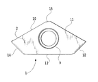
- the cutting insert 1 which concerns on 1st Embodiment is between the upper surface 2 and the lower surface 3 which have a polygon-shaped external shape, and these upper surface 2 and the lower surface 3.
- a plurality of side surfaces 4, 5, 6, 7, 8 that extend and a mounting hole 9 that penetrates the upper surface 2 and the lower surface 3 are defined.
- the upper surface 2 and the lower surface 3 have the same shape and face each other so as to be substantially parallel.
- the upper surface 2 has a symmetrical shape when viewed from the top.
- the lower surface 3 has a symmetrical shape.
- the one located on the upper left side is the first intersecting portion 10, and the first intersecting portion 10 and the upper right side adjacent to each other via the chamfered portion 15 serving as a connecting portion.
- the one located at is the second intersection 11.
- what is located on the lower left side arranged at the position adjacent to the first intersection 10 is located on the lower right side arranged at the position adjacent to the third intersection 14 and the second intersection 11.
- a portion disposed between the third intersecting portion 14 and the fourth intersecting portion 12, that is, at a position adjacent to both, is referred to as a fifth intersecting portion 13.
- the first intersection 10 and the second intersection 11 have the same length.
- the fourth intersection 12 and the third intersection 14 have the same length.
- the first intersection 10 and the second intersection 11 are longer than both the fourth intersection 12 and the third intersection 14.
- the connecting portion such as the chamfered portion 15
- the outer shapes of the upper surface 2 and the lower surface 3 are substantially pentagonal symmetrical, and the first intersecting portion 10 and the second intersecting portion 11 are formed.
- the length is the same, and the lengths of the fourth intersection 12 and the third intersection 14 are the same.
- the present invention is not limited to this, and the outer shapes of the upper surface 2 and the lower surface 3 may be asymmetrical.
- the lengths of the first intersection 10 and the second intersection 11 may be different.
- the lengths of the fourth intersection 12 and the third intersection 14 may be different. What is important is that the lengths of the first intersection 10 and the second intersection 11 are longer than the lengths of the fourth intersection 12 and the third intersection 14, respectively.
- the connecting portion may have any shape.
- this embodiment demonstrates the case where it has five crossing parts 10, 11, 12, 13, and 14, you may have a larger number of crossing parts.
- the term “adjacent” used to indicate the positional relationship between the five intersections 10, 11, 12, 13, and 14, that is, the relationship between the sides of the substantially polygonal outer shape, is used in this specification. It is not limited to the case where the intersecting portions are directly connected to each other, but includes that they are connected via a connecting portion such as a chamfer.
- Cutting edges are formed at the intersections 10 and 11 between the upper surface 2 or the lower surface 3 and the side surfaces 4 and 5.
- cutting edges are formed at the first intersecting portion 10 and the second intersecting portion 11 on the upper surface 2 and the lower surface 3, respectively.
- Honing may be given to the 1st intersection 10 and the 2nd intersection 11 in which the cutting edge was formed.
- a land may be provided adjacent to the cutting edge.
- rake surfaces 4a and 5a are formed, respectively. These rake surfaces 4 a and 5 a are formed so as to be gradually inclined from the first intersection 10 or the second intersection 11 toward the inside of the cutting insert 1.
- the side surfaces 4 and 5 are formed flat except for the inclined rake surfaces 4a and 5a.
- the shape of the side surfaces 4 and 5 is not limited to this, There may be no flat part, and it may be comprised by the inclined surface, and may be formed by the curved surface.
- the upper surface 2 and the lower surface 3 function as contact surfaces for the cutting insert 1 to contact an insert seating portion 24 of the tool body 22 described later, and also function as flank surfaces for forming the above-described cutting blade. When used so that the upper surface 2 becomes a flank, the lower surface 3 functions as a contact surface, and when used so that the lower surface 3 becomes a flank surface, the upper surface 2 functions as a contact surface.
- the first intersection 10 and the second intersection 11 are 75 ° or more in a top view. It intersects within a range of 150 ° or less.
- a chamfered portion 15 is provided at a connection portion between the first intersecting portion 10 and the second intersecting portion 11.
- the shape of the chamfered portion 15 can be changed as appropriate according to the type of work material to be processed and the shape of the groove. Further, it is preferable that round honing or chamfer honing is applied to the intersection between the upper surface 2 or the lower surface 3 and the side surface 6 or the side surface 8.
- the shape of the R processing or chamfering can be appropriately changed according to the type of work material to be processed, the shape of the groove, and the like.
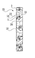
- FIG. 2 shows a rotary cutting tool 21 equipped with the cutting insert 1 of the first embodiment.
- the tool body 22 is basically composed of two substantially circular end faces, an outer peripheral face connecting the two end faces, and a bore penetrating the center of the two end faces.
- a chip pocket 23 for discharging chips, and an insert seating portion 24 provided on the outer peripheral surface on the rear side in the tool rotation direction K adjacent to the chip pocket 23. And are formed.
- FIGS. 2A to 2C for example, when the cutting edge of the upper surface 2 of the cutting insert 1 is used, the cutting insert 1 is separated from the cutting edge of the first intersection 10 and the second intersection.
- the cutting edges of the part 11 are arranged on the insert seating part 24 so as to be used alternately in the circumferential direction of the tool body 22.
- the cutting inserts 1 are alternately arranged in the circumferential direction of the tool body 22 with the right hand and the left hand.
- the cutting edge on the lower surface 3 of the cutting insert 1 is also used, in the case of the right hand, the first intersecting portion 10 on the upper surface 2 of the cutting insert 1 or the second intersecting portion 11 on the lower surface 3 is the cutting edge.
- the tool body 22 is used so that the second intersection 11 on the upper surface 2 or the first intersection 10 on the lower surface 3 is used as a cutting edge. It is attached to.
- a part of the side surface of the cutting insert 1 is mounted so as to substantially coincide with the position of the two end surfaces of the tool body 22. Furthermore, the plurality of inserts 1 are slots having a width substantially corresponding to the width of the outer peripheral surface of the tool body 22 by the cooperation of the cutting edge of the first intersecting portion 10 and the cutting edge of the second intersecting portion 11. The cutting is arranged.
- the cutting insert 1 according to the present embodiment is not rectangular, but has two cutting edges for right hand and two cutting edges for left hand, for a total of four cutting edges. For this reason, it is possible to take a wide back support portion on the rear side in the tool rotation direction K as compared with a conventional rectangular cutting insert. Therefore, chattering and breakage of the back support portion are suppressed even when subjected to strong cutting resistance, and the cutting insert 1 is firmly held. Furthermore, since the cutting force applied to the cutting insert 1 can be supported by the holding force in the two directions of the side surface 7 and the side surface 6 or the side surface 7 and the side surface 8 connected in a V shape, the cutting force is received more efficiently and reliably. It is possible.
- the area of the location where the cutting force is received (that is, the total area of the side surface 7 and the side surface 6 or the total area of the side surface 7 and the side surface 8) is compared with the area of the receiving location of the conventional rectangular cutting insert. Therefore, the holding force per unit area can be reduced. Further, since the distance between the first intersecting portion 10 or the second intersecting portion 11 where the cutting edge is formed and the fifth intersecting portion 13 receiving the cutting resistance can be shortened, the moment of the cutting resistance can be suppressed. Accordingly, the moment applied to the screw is also reduced, so that plastic deformation of the screw can be suppressed.
- the distance between the cutting inserts it is necessary to arrange the distance between the cutting inserts to some extent in order to secure the necessary size of the back support part of the tool body.
- the distance between the cutting inserts can be reduced. Therefore, when the size of the tool main body is the same, the number of cutting inserts that can be mounted on the tool main body can be increased as compared with the conventional case, and it becomes possible to perform cutting with higher efficiency. Further, when the distance between the cutting inserts is made the same as the conventional one, the chip pocket 23 can be made larger than the conventional one. Therefore, chip discharge efficiency can be improved.
- the processed surface of the work material can be satisfactorily finished. That is, by chamfering the corner between the first intersecting portion 10 and the second intersecting portion 11, the possibility that the work surface of the work material is damaged during cutting can be reduced.
- R processing or chamfering can be performed according to the material of the work material, the shape of the groove, processing conditions, and the like. As a result, the possibility of damaging the work surface of the work material is reduced, so that a good work surface can be obtained.
- the cutting insert 1 of the present embodiment has the same cutting edge length as the conventional rectangular cutting insert, but the size (volume) of the cutting insert is greatly reduced. Therefore, it is possible to reduce the raw material of the insert, and thus it is possible to greatly reduce the manufacturing cost of the insert.
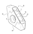
- the fifth intersection 13 on each of the upper surface 2 and the lower surface 3 is provided. It is configured to be used as a cutting edge.
- the number of cutting edges according to the present embodiment is six, including two cutting edges for the left hand, two cutting edges for the right hand, and two cutting edges in the center. Honing may be given to the 5th crossing part 13 which is a cutting edge.
- a rake face 7a is formed on the side face 7 in contact with the fifth intersecting portion 13 on the upper and lower surfaces.
- the rake face 7 a is formed so as to be gradually inclined from the fifth intersection 13 toward the inside of the cutting insert 31.
- the bottom portion having the lowest height from the fifth intersecting portion 13 may be formed flat or may be formed by a curved surface, You may form with the inclined surface which cross
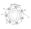
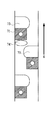
- 4A to 4C show a rotary cutting tool 41 equipped with the cutting insert 31 of the second embodiment.
- a disk-shaped tool body 42 defines first and second end faces 42a and 42b facing each other and an outer peripheral face extending between the first and second end faces 42a and 42b.
- a plurality of insert seating portions 44A, 44B, and 44C are formed on the outer peripheral surface of the tool body 42 along the circumferential direction.
- a chip pocket 43 is provided on the front side in the tool rotation direction (K) for each of the plurality of insert seats 44A, 44B, 44C.
- Cutting inserts 31A to 31C are mounted on the insert seat portions 44A, 44B, and 44C, respectively.
- the cutting inserts 31A to 31C have the same structure as the cutting insert 31 described with reference to FIG. 3, but the reference numerals are different for convenience of description.
- the cutting insert 31A is disposed on the right hand side
- the cutting insert 31B is disposed on the left hand side
- the cutting insert 31C is disposed on the central portion of the outer peripheral surface.
- the insert seating portions 44 ⁇ / b> A and 44 ⁇ / b> B and the insert seating portion 44 ⁇ / b> C are alternately arranged in the circumferential direction of the outer peripheral surface of the tool main body 42.
- the seating portion 44A arranges the cutting insert 31A closer to the first end face 42a so that the cutting edge of the first intersecting portion 10 of the cutting insert 31A is used.
- the seating portion 44B arranges the cutting insert 31B closer to the second end face 42b so that the cutting edge of the second intersecting portion 11 of the cutting insert 31B is used.
- the seating portion 44C arranges the cutting insert 31C approximately at the center between the first and second end faces 42a and 42b so that the cutting edge of the fifth intersecting portion 13 of the cutting insert 31C is used.
- the seating part 44A arrange
- the part 44B arrange
- cutting edges can be arranged in the entire width direction W of the groove to be processed.
- the two cutting inserts 31A and 31B that are paired in the arrangement of the right hand and the left hand may have their respective cutting edges arranged at the same position in the rotation direction K of the tool body 42, or either One side may be shifted rearward. When either one is shifted and arranged, an additional chip pocket is provided in the shifted tool body 42.
- the additional cutting insert 31C it is possible to cope with grooving with a wider width by the additional cutting insert 31C while having the characteristics of the first embodiment. That is, when machining a groove having a width wider than the combined length of the first intersecting portion 10 and the second intersecting portion 11 that are cutting edges, in order to compensate for the insufficient length if it is conventional. Another kind of cutting insert needs to be introduced.
- the present embodiment by using the fifth intersecting portion 13 as a cutting edge, it is possible to compensate for the shortage using the cutting insert 31 having the same structure. Therefore, since the wide groove processing can be performed by using the cutting insert 31 having the same structure, the increase in cost can be suppressed and the management of the tool becomes easy.
- the present embodiment is configured to use a side surface intersection portion 52 between the side surface 4 and the side surface 8 and a side surface intersection portion 53 between the side surface 5 and the side surface 6 as a cutting blade. It is a thing. Cutting edges are not formed except for these side crossing portions 52 and 53.
- rake surfaces 4b and 5b are formed on the side surfaces 4 and 5, rake surfaces 4b and 5b are formed. The rake surfaces 4b and 5b are formed so as to be gradually inclined toward the inner side of the cutting insert 51 from the side surface intersection.
- the bottom portion may be formed as a flat surface, may be formed as a curved surface, or may be formed as a plurality of intersecting inclined surfaces. Honing may be applied to the side surface intersection where the blade is formed.
- the cutting edge was formed in both the side surface intersection parts 52 and 53, it is not necessarily limited to this, You may form only in any one.
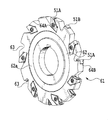
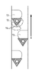
- FIG. 6 shows a rotary cutting tool 61 equipped with the cutting insert 51 of the third embodiment.
- the disk-shaped tool body 62 of the rotary cutting tool 61 defines first and second end faces 62a and 62b facing each other and an outer peripheral face extending between the first and second end faces 62a and 62b.
- a plurality of insert seat portions 64A and 64B are formed on the outer peripheral surface of the tool body 62 along the circumferential direction.
- the insert seats 64A and the insert seats 64B are alternately provided in the circumferential direction of the outer peripheral surface.
- a chip pocket 63 is provided on the front side in the tool rotation direction (K) with respect to each of the plurality of insert seats 64.
- Cutting inserts 51A and 51B are mounted on the insert seats 64A and 64B, respectively.
- the cutting inserts 51A and 51B have the same structure as the cutting insert 51 described with reference to FIG.
- the cutting insert 51A For the seating portion 64A, one cutting edge of the first and second side crossing portions 52 and 53 of the cutting insert 51A is used, and the upper surface 2 or the lower surface 3 of the cutting insert 51A is outside the first end surface 62a.
- the cutting insert 51A is disposed closer to the first end face 62a so as to be exposed to the surface.
- the seating portion 64B one cutting edge of the first and second side surface intersecting portions 52 and 53 of the cutting insert 51B is used, and the upper surface 2 or the lower surface 3 of the cutting insert 51B is outside the second end surface 62b.
- the cutting insert 51B is disposed near the second end face 62b so as to be exposed to the surface. Thereby, the 1st or 2nd side surface crossing parts 52 and 53 participate in cutting.
- the cutting insert 51 is screwed from either end face side of the tool main body 62.
Abstract
Description
前記上面(2)は、前記複数の側面(4、5、6、7、8)と交差する、少なくとも5つの交差部をそれぞれ有し、
第1の交差部(10)と第2の交差部(11)とが互いに隣り合う位置に配置され、
第3の交差部(14)は、前記第1の交差部(10)と隣り合う位置に配置され、
第4の交差部(12)は、前記第2の交差部(11)と隣り合う位置に配置され、
前記第3および第4の交差部(14,12)は、前記第1および第2の交差部(10,11)よりも長さがそれぞれ短く、
前記第1および第2の交差部(10,11)には、切れ刃がそれぞれ形成され、
前記複数の側面(4、5、6、7、8)のうち、前記第1および第2の交差部(10,11)に対応する側面(4,5)には、すくい面(4a,5a)がそれぞれ形成され、
前記上面(2)には、切れ刃を形成するための逃げ面が形成されている、ことを特徴とする。
当該第5の交差部(13)に対応する側面(7)にすくい面が形成され、
前記上面(2)には、当該第5の交差部(13)の切れ刃を形成するための逃げ面が形成されている、構成の切削インサート(31)を採用できる。
前記外周面の周方向に沿って形成された複数のインサート着座部(24)と、
前記複数のインサート着座部(24)の各々に対して工具回転方向(K)の前方側に設けられた複数の切りくずポケット(23)と、
前記複数のインサート着座部(24)の各々に装着された複数の上記切削インサート(1)と、を有し、
前記複数のインサート着座部(24)は、前記切削インサートの前記第1の交差部(10)の切れ刃と、前記第2の交差部(11)の切れ刃とが前記工具本体(22)の周方向において交互に使用されるように、前記複数の切削インサートを配置する、ことを特徴とする。
前記外周面の周方向に沿って形成された複数のインサート着座部(44)と、
前記複数のインサート着座部(44)の各々に対して工具回転方向(K)の前方側に設けられた複数の切りくずポケット(43)と、前記複数のインサート着座部(44)の各々に装着された複数の上記切削インサート(31)と、を有し、
前記複数のインサート着座部(44)は、一対の前記切削インサート(31A,31,B)を装着するための第1および第2の着座部(44A,44B)と、単独の前記切削インサート(31C)を装着するための第3の着座部(44C)とを含み、
前記第1および第2の着座部(44A,44B)と、前記第3の着座部(44C)とは、前記外周面の周方向において交互に配置され、
前記第1の着座部(44A)は、前記切削インサート(31A)の第1の交差部(10)の切れ刃が使用されるように、当該切削インサート(31A)を前記第1の端面寄りに配置し、
前記第2の着座部(44B)は、前記切削インサート(31B)の第2の交差部(11)の切れ刃が使用されるように、当該切削インサート(31B)を前記第2の端面寄りに配置し、
前記第3の着座部(44C)は、前記切削インサート(31C)の前記少なくとも第5の交差部(13)の切れ刃が使用されるように、当該切削インサート(31C)を前記第1および第2の端面の間の略中央に配置する、ことを特徴とする。
前記上面(2)は、前記複数の側面(4、5、6、7、8)と交差する、少なくとも5つの交差部をそれぞれ有し、
第1の交差部(10)と第2の交差部(11)とが互いに隣り合う位置に配置され、
第3の交差部(14)は、前記第1の交差部(10)と隣り合う位置に配置され、
第4の交差部(12)は、前記第2の交差部(11)と隣り合う位置に配置され、
前記第3および第4の交差部(14,12)は、前記第1および第2の交差部(10,11)よりも長さがそれぞれ短く、
前記第1の交差部(10)に対応する側面(4)と前記第3および第4の交差部(14,12)の一方に対応する側面(8)との第1の側面交差部(52)と、前記第2の交差部(11)に対応する側面(5)と前記第3および第4の交差部(14,12)の他方に対応する側面(6)との第2の側面交差部(53)との少なくとも一方に切れ刃が形成され、
前記第3および第4の交差部(14、12)に対応する側面(6,8)の少なくとも一方には、前記切れ刃を形成するための逃げ面が形成されている、ことを特徴とする。
前記外周面の周方向に沿って形成された複数のインサート着座部(64)と、
前記複数のインサート着座部(64)の各々に対して工具回転方向(K)の前方側に設けられた複数の切りくずポケット(63)と、前記複数のインサート着座部(64)の各々に装着された請求項5に記載の複数の切削インサート(51)と、を有し、
前記複数のインサート着座部(64)は、単独の前記切削インサート(51A)を装着するための第1の着座部(64A)と、単独の前記切削インサート(51B)を装着するための第2の着座部(64B)とを含み、
前記第1の着座部(64A)と前記第2の着座部(64B)とは、前記外周面の周方向において交互に設けられ、
前記第1の着座部(64A)は、前記切削インサート(51A)の第1および第2の側面交差部(52,53)の一方の切れ刃が使用されるとともに、当該切削インサート(51A)の上面又は下面が前記第1の端面から外側に露出するように当該切削インサート(51B)を当該第1の端面寄りに配置し、
前記第2の着座部(64B)は、前記切削インサート(51B)の前記切削インサート(51A)の第1および第2の側面交差部(52,53)の一方の切れ刃が使用されるとともに、当該切削インサート(51B)の上面又は下面が前記第2の端面から外側に露出するように当該切削インサート(51B)を当該第2の端面寄りに配置する、ことを
特徴とする。
図1に示されているように、第1の実施形態に係る切削インサート1は、多角形状の外形をもつ上面2及び下面3と、それら上面2と下面3との間で延在する複数の側面4、5、6、7、8と、上面2及び下面3を貫通する取付穴9とを画定している。上面2と下面3とは、同一の形状であり、略平行となるように対向している。
また、切削インサート1の側面の一部は、工具本体22の2の端面の位置と略一致するように装着されている。さらに、複数のインサート1は、第1の交差部10の切れ刃と、第2の交差部11の切れ刃とが協働して、工具本体22の外周面の幅に略相当する幅のスロットを切削可能に配置される。
次に、本発明の第2の実施形態について図3を参照しながら説明する。本実施形態の切削インサート31において、第1の実施形態の切削インサート1と構成が同様の部分については説明を省略する。
次に、第3の実施形態の切削インサート51について図5を参照しながら説明する。本実施形態の切削インサートにおいて、第1の実施形態の切削インサートと構成が同一の箇所については説明を省略する。
2 切削インサートの上面
3 切削インサートの下面
4~8 切削インサートの側面
9 取付穴
10 第1の交差部
11 第2の交差部
12 第3の交差部
14 第4の交差部
13 第5の交差部
15 面取り部
21,41,61 回転切削工具
22,42,62 工具本体
23,43,63 切りくずポケット
24,44,64 インサート着座部
52 側面交差部
53 側面交差部
K 工具回転方向
Claims (10)
- 略多角形状の外形を有する上面(2)と、前記上面(2)と対向する下面(3)と、前記上面(2)と前記下面(3)との間で延びる複数の側面(4、5、6、7、8)と、前記上面(2)と前記下面(3)とを貫通する取付穴(9)と、を有する板状の切削インサートであって、
前記上面(2)は、前記複数の側面(4、5、6、7、8)と交差する、少なくとも5つの交差部をそれぞれ有し、
第1の交差部(10)と第2の交差部(11)とが互いに隣り合う位置に配置され、
第3の交差部(14)は、前記第1の交差部(10)と隣り合う位置に配置され、
第4の交差部(12)は、前記第2の交差部(11)と隣り合う位置に配置され、
前記第3および第4の交差部(14,12)は、前記第1および第2の交差部(10,11)よりも長さがそれぞれ短く、
前記第1および第2の交差部(10,11)には、切れ刃がそれぞれ形成され、
前記複数の側面(4、5、6、7、8)のうち、前記第1および第2の交差部(10,11)に対応する側面(4,5)には、すくい面(4a,5a)がそれぞれ形成され、
前記上面(2)には、切れ刃を形成するための逃げ面が形成されている、ことを特徴とする切削インサート(1)。 - 前記少なくとも5つの交差部のうちの、前記第1および第2の交差部(10,11)と前記第3および第4の交差部(14,12)とを除く第5の交差部(13)は、前記第3および第4の交差部(14、12)の少なくとも一方と隣り合う位置に配置され、当該第5の交差部(13)には、切れ刃が形成され、
当該第5の交差部(13)に対応する側面(7)にすくい面が形成され、
前記上面(2)には、当該第5の交差部(13)の切れ刃を形成するための逃げ面が形成されている、ことを特徴とする切削インサート(31)。 - 前記第1の交差部(10)と前記第2の交差部(11)とは、上面視において、これらの延長線が75°以上150°以下の角度で交差するように配置されている、ことを特徴とする請求項1又は2に記載の切削インサート。
- 前記第1の交差部(10)と前記第2の交差部(11)とを接続する接続部には、面取り部(15)が設けられていることを特徴とする請求項1ないし3のいずれかに記載の切削インサート。
- 前記上面(2)は、略5角形状の外形を有し、
前記第5の交差部(13)は、前記第3および第4の交差部(14,12)の両方に隣り合う位置に配置されている、ことを特徴とする請求項1ないし4のいずれかに記載の切削インサート。 - 略多角形状の外形を有する上面(2)と、前記上面(2)と対向する下面(3)と、前記上面(2)と前記下面(3)との間で延びる複数の側面(4、5、6、7、8)と、前記上面(2)と前記下面(3)とを貫通する取付穴(9)と、を有する板状の切削インサート(51)であって、
前記上面(2)は、前記複数の側面(4、5、6、7、8)と交差する、少なくとも5つの交差部をそれぞれ有し、
第1の交差部(10)と第2の交差部(11)とが互いに隣り合う位置に配置され、
第3の交差部(14)は、前記第1の交差部(10)と隣り合う位置に配置され、
第4の交差部(12)は、前記第2の交差部(11)と隣り合う位置に配置され、
前記第3および第4の交差部(14,12)は、前記第1および第2の交差部(10,11)よりも長さがそれぞれ短く、
前記第1の交差部(10)に対応する側面(4)と前記第3および第4の交差部(14,12)の一方に対応する側面(8)との第1の側面交差部(52)と、前記第2の交差部(11)に対応する側面(5)と前記第3および第4の交差部(14,12)の他方に対応する側面(6)との第2の側面交差部(53)との少なくとも一方に切れ刃が形成され、
前記第3および第4の交差部(14、12)に対応する側面(6,8)の少なくとも一方には、前記切れ刃を形成するための逃げ面が形成されている、ことを特徴とする切削インサート。 - 対向する第1および第2の端面と、当該第1および第2の端面間で延びる外周面とを画定する円盤状の工具本体(22)と、
前記外周面の周方向に沿って形成された複数のインサート着座部(24)と、
前記複数のインサート着座部(24)の各々に対して工具回転方向(K)の前方側に設けられた複数の切りくずポケット(23)と、
前記複数のインサート着座部(24)の各々に装着された請求項1から5のいずれかに記載の複数の切削インサートと、を有し、
前記複数のインサート着座部(24)は、前記切削インサートの前記第1の交差部(10)の切れ刃と、前記第2の交差部(11)の切れ刃とが前記工具本体(22)の周方向において交互に使用されるように、前記複数の切削インサートを配置する、ことを特徴とする刃先交換式回転切削工具。 - 前記複数のインサートは、前記切削インサートの前記第1の交差部(10)の切れ刃と、前記第2の交差部(11)の切れ刃とが協働して、前記工具本体の外周面の幅に略相当する幅のスロットを切削可能に配置されている、ことを特徴とする請求項7に記載の刃先交換式回転切削工具。
- 対向する第1および第2の端面と、当該第1および第2の端面間で延びる外周面とを画定する円盤状の工具本体(42)と、
前記外周面の周方向に沿って形成された複数のインサート着座部(44)と、
前記複数のインサート着座部(44)の各々に対して工具回転方向(K)の前方側に設けられた複数の切りくずポケット(43)と、前記複数のインサート着座部(44)の各々に装着された請求項2から5のいずれかに記載の複数の切削インサート(31)と、を有し、
前記複数のインサート着座部(44)は、一対の前記切削インサート(31A,31,B)を装着するための第1および第2の着座部(44A,44B)と、単独の前記切削インサート(31C)を装着するための第3の着座部(44C)とを含み、
前記第1および第2の着座部(44A,44B)と、前記第3の着座部(44C)とは、前記外周面の周方向において交互に配置され、
前記第1の着座部(44A)は、前記切削インサート(31A)の第1の交差部(10)の切れ刃が使用されるように、当該切削インサート(31A)を前記第1の端面寄りに配置し、
前記第2の着座部(44B)は、前記切削インサート(31B)の第2の交差部(11)の切れ刃が使用されるように、当該切削インサート(31B)を前記第2の端面寄りに配置し、
前記第3の着座部(44C)は、前記切削インサート(31C)の前記少なくとも第5の交差部(13)の切れ刃が使用されるように、当該切削インサート(31C)を前記第1および第2の端面の間の略中央に配置する、ことを特徴とする刃先交換式回転切削工具。 - 対向する第1および第2の端面と、当該第1および第2の端面間で延びる外周面とを画定する円盤状の工具本体(62)と、
前記外周面の周方向に沿って形成された複数のインサート着座部(64)と、
前記複数のインサート着座部(64)の各々に対して工具回転方向(K)の前方側に設けられた複数の切りくずポケット(63)と、前記複数のインサート着座部(64)の各々に装着された請求項6に記載の複数の切削インサート(51)と、を有し、
前記複数のインサート着座部(64)は、単独の前記切削インサート(51A)を装着するための第1の着座部(64A)と、単独の前記切削インサート(51B)を装着するための第2の着座部(64B)とを含み、
前記第1の着座部(64A)と前記第2の着座部(64B)とは、前記外周面の周方向において交互に設けられ、
前記第1の着座部(64A)は、前記切削インサート(51A)の第1および第2の側面交差部(52,53)の一方の切れ刃が使用されるとともに、当該切削インサート(51A)の上面又は下面が前記第1の端面から外側に露出するように当該切削インサート(51A)を当該第1の端面寄りに配置し、
前記第2の着座部(64B)は、前記切削インサート(51B)の第1および第2の側面交差部(52,53)の一方の切れ刃が使用されるとともに、当該切削インサート(51B)の上面又は下面が前記第2の端面から外側に露出するように当該切削インサート(51B)を当該第2の端面寄りに配置する、ことを
特徴とする刃先交換式回転切削工具。
Priority Applications (5)
| Application Number | Priority Date | Filing Date | Title |
|---|---|---|---|
| CN2012800150811A CN103442832A (zh) | 2011-04-25 | 2012-04-11 | 切削刀片和可转位旋转切削工具 |
| JP2013511998A JP5842913B2 (ja) | 2011-04-25 | 2012-04-11 | 切削インサート及び刃先交換式回転切削工具 |
| RU2013143313/02A RU2013143313A (ru) | 2011-04-25 | 2012-04-11 | Режущая вставка и индексируемый вращающийся режущий инструмент |
| BR112013024524A BR112013024524A2 (pt) | 2011-04-25 | 2012-04-11 | inserto de corte tipo placa, e, ferramenta de corte rotativa indexável |
| US13/739,910 US20130129434A1 (en) | 2011-04-25 | 2013-01-11 | Cutting Insert and Indexable Rotary Cutting Tool |
Applications Claiming Priority (2)
| Application Number | Priority Date | Filing Date | Title |
|---|---|---|---|
| JP2011-097343 | 2011-04-25 | ||
| JP2011097343 | 2011-04-25 |
Related Child Applications (1)
| Application Number | Title | Priority Date | Filing Date |
|---|---|---|---|
| US13/739,910 Continuation-In-Part US20130129434A1 (en) | 2011-04-25 | 2013-01-11 | Cutting Insert and Indexable Rotary Cutting Tool |
Publications (1)
| Publication Number | Publication Date |
|---|---|
| WO2012147513A1 true WO2012147513A1 (ja) | 2012-11-01 |
Family
ID=47072036
Family Applications (1)
| Application Number | Title | Priority Date | Filing Date |
|---|---|---|---|
| PCT/JP2012/059856 WO2012147513A1 (ja) | 2011-04-25 | 2012-04-11 | 切削インサート及び刃先交換式回転切削工具 |
Country Status (6)
| Country | Link |
|---|---|
| US (1) | US20130129434A1 (ja) |
| JP (1) | JP5842913B2 (ja) |
| CN (1) | CN103442832A (ja) |
| BR (1) | BR112013024524A2 (ja) |
| RU (1) | RU2013143313A (ja) |
| WO (1) | WO2012147513A1 (ja) |
Cited By (1)
| Publication number | Priority date | Publication date | Assignee | Title |
|---|---|---|---|---|
| JP2019518617A (ja) * | 2016-06-22 | 2019-07-04 | イスカル リミテッド | ランピング用インサートおよび高送りフライス工具アセンブリ |
Families Citing this family (8)
| Publication number | Priority date | Publication date | Assignee | Title |
|---|---|---|---|---|
| WO2012114848A1 (ja) * | 2011-02-24 | 2012-08-30 | 株式会社タンガロイ | 切削インサート及び刃先交換式エンドミル |
| US9527142B2 (en) * | 2013-02-19 | 2016-12-27 | Iscar, Ltd. | High speed milling tool and tangential ramping milling insert therefor |
| US9296054B2 (en) * | 2013-05-23 | 2016-03-29 | Kennametal Inc. | Indexable cutting insert with a triangular shape |
| US9205499B2 (en) * | 2013-09-11 | 2015-12-08 | Kennametal Inc. | Cutting insert with finishing and roughing cutting edges |
| US9475138B2 (en) | 2014-01-22 | 2016-10-25 | Kennametal Inc. | Cutting tool having insert pocket with cantilevered member |
| US10010942B2 (en) * | 2016-06-20 | 2018-07-03 | Iscar, Ltd. | Cutting tool and cutting insert having a deep blind opening |
| CN106312160A (zh) * | 2016-09-22 | 2017-01-11 | 成都飞机工业(集团)有限责任公司 | 可变刃宽组合铣刀 |
| EP3375552B1 (en) * | 2017-03-13 | 2022-12-21 | Sandvik Intellectual Property AB | Milling tool comprising a kit for the milling tool |
Citations (5)
| Publication number | Priority date | Publication date | Assignee | Title |
|---|---|---|---|---|
| JPH0512027A (ja) | 1991-07-04 | 1993-01-22 | Nec Corp | 携帯型端末装置システムの動作環境構築システム |
| JPH0631579A (ja) | 1992-07-20 | 1994-02-08 | Genichi Sato | 切削工具 |
| JPH07237027A (ja) * | 1994-02-28 | 1995-09-12 | Mitsubishi Materials Corp | スローアウェイチップ及び切削工具 |
| JP2007125669A (ja) * | 2005-11-07 | 2007-05-24 | Sumitomo Electric Hardmetal Corp | 刃先交換式チップと刃先交換式隅削りフライスカッタ |
| JP2007283473A (ja) * | 2006-03-22 | 2007-11-01 | Nippon Project Kk | ドリル、穿孔用壁面保護部材及び穿孔方法 |
Family Cites Families (13)
| Publication number | Priority date | Publication date | Assignee | Title |
|---|---|---|---|---|
| FR1508567A (fr) * | 1966-01-25 | 1968-01-05 | Montanwerke Walter Ag | élément de coupe, de préférence en métal dur, en forme de plaquette de coupe àplusieurs tranchants, pour garnir des outils tournants équipés de dispositifs de serrage, en particulier pour l'usinage de métaux, et outils garnis de telles plaquettes |
| US4090801A (en) * | 1975-01-23 | 1978-05-23 | Sandvik Aktiebolag | Cutting insert and rotary milling cutter |
| US4297058A (en) * | 1980-06-30 | 1981-10-27 | Kennametal Inc. | Indexable cutting insert |
| JPS6265109U (ja) * | 1985-10-08 | 1987-04-22 | ||
| US5067858A (en) * | 1991-04-10 | 1991-11-26 | Cook Warren R | Multiple faced cutter insert |
| TW431922B (en) * | 1998-04-29 | 2001-05-01 | Iscar Ltd | A cutting insert and a cutting tool assembly |
| DE10159512A1 (de) * | 2001-12-04 | 2003-06-12 | Kennametal Inc | Zerspanungswerkzeug |
| US20040253063A1 (en) * | 2003-05-29 | 2004-12-16 | Arm Tooling, Inc. | Cutting tool insert and cutter body |
| IL159157A (en) * | 2003-12-02 | 2008-03-20 | Amir Satran | Rotary slot milling cutter and cutting insert therefor |
| DE102006034673A1 (de) * | 2006-07-24 | 2008-01-31 | Walter Ag | Kurbelwellenfräser |
| KR100937459B1 (ko) * | 2008-03-26 | 2010-01-19 | 대구텍 유한회사 | 접선 방향 절삭 인서트 |
| EP2404690B1 (en) * | 2009-03-06 | 2020-04-15 | Mitsubishi Materials Corporation | Cutting inset and tool having cutting inserts |
| CN201744720U (zh) * | 2010-07-29 | 2011-02-16 | 四川天虎工具有限责任公司 | 机夹多工位铣刀 |
-
2012
- 2012-04-11 BR BR112013024524A patent/BR112013024524A2/pt not_active IP Right Cessation
- 2012-04-11 WO PCT/JP2012/059856 patent/WO2012147513A1/ja active Application Filing
- 2012-04-11 RU RU2013143313/02A patent/RU2013143313A/ru not_active Application Discontinuation
- 2012-04-11 CN CN2012800150811A patent/CN103442832A/zh active Pending
- 2012-04-11 JP JP2013511998A patent/JP5842913B2/ja active Active
-
2013
- 2013-01-11 US US13/739,910 patent/US20130129434A1/en not_active Abandoned
Patent Citations (5)
| Publication number | Priority date | Publication date | Assignee | Title |
|---|---|---|---|---|
| JPH0512027A (ja) | 1991-07-04 | 1993-01-22 | Nec Corp | 携帯型端末装置システムの動作環境構築システム |
| JPH0631579A (ja) | 1992-07-20 | 1994-02-08 | Genichi Sato | 切削工具 |
| JPH07237027A (ja) * | 1994-02-28 | 1995-09-12 | Mitsubishi Materials Corp | スローアウェイチップ及び切削工具 |
| JP2007125669A (ja) * | 2005-11-07 | 2007-05-24 | Sumitomo Electric Hardmetal Corp | 刃先交換式チップと刃先交換式隅削りフライスカッタ |
| JP2007283473A (ja) * | 2006-03-22 | 2007-11-01 | Nippon Project Kk | ドリル、穿孔用壁面保護部材及び穿孔方法 |
Cited By (2)
| Publication number | Priority date | Publication date | Assignee | Title |
|---|---|---|---|---|
| JP2019518617A (ja) * | 2016-06-22 | 2019-07-04 | イスカル リミテッド | ランピング用インサートおよび高送りフライス工具アセンブリ |
| JP7008037B2 (ja) | 2016-06-22 | 2022-01-25 | イスカル リミテッド | ランピング用インサートおよび高送りフライス工具アセンブリ |
Also Published As
| Publication number | Publication date |
|---|---|
| RU2013143313A (ru) | 2015-05-27 |
| JPWO2012147513A1 (ja) | 2014-07-28 |
| BR112013024524A2 (pt) | 2019-09-24 |
| US20130129434A1 (en) | 2013-05-23 |
| CN103442832A (zh) | 2013-12-11 |
| JP5842913B2 (ja) | 2016-01-13 |
Similar Documents
| Publication | Publication Date | Title |
|---|---|---|
| JP5842913B2 (ja) | 切削インサート及び刃先交換式回転切削工具 | |
| JP6580572B2 (ja) | 割出し可能な両面切削インサートおよびそれ用の切削工具 | |
| US8419320B2 (en) | Milling cutting tool employing a cutting insert | |
| KR101292441B1 (ko) | 접선식 절삭 삽입체 | |
| JP4763855B2 (ja) | 切削インサート及び切削工具、並びにそれを用いた被削材の切削方法 | |
| RU2519208C2 (ru) | Режущая пластина и вращающийся режущий инструмент | |
| WO2012046556A1 (ja) | 切削インサートおよび切削工具、並びにそれらを用いた切削加工物の製造方法 | |
| WO2012020784A1 (ja) | 切削インサートおよび切削工具、並びにそれらを用いた切削加工物の製造方法 | |
| US20110164932A1 (en) | Cutting Insert and Milling Cutter Provided with the Same | |
| US9370833B2 (en) | Cutting insert and indexable rotary cutting tool | |
| US20120308317A1 (en) | Cutting Insert Having Cutting Edges Divided By Recesses and a Milling Cutter Provided with the Same | |
| KR20150008430A (ko) | 숄더 밀링 커터용 위치조정가능한 인서트 및 위치조정가능한 인서트용 장착 절취부들을 가진 숄더 밀링 커터 | |
| JP6052455B1 (ja) | 切削インサートおよび切削工具 | |
| JP6966329B2 (ja) | 菱形のインサート及び支持座を備えたアセンブリ、並びに菱形の可逆切削インサート | |
| EP2939780A1 (en) | Cutting insert and rotary cutting tool with replaceable blade edge | |
| KR20210141534A (ko) | 대각선으로 대향된 상승 코너와 대각선으로 대향된 하강 코너를 가지는 양면 커팅 인서트 및 로터리 커팅 도구 | |
| JP5938868B2 (ja) | 切削インサートおよび刃先交換式切削工具 | |
| IL273408B2 (en) | A square cutting tool with rounded secondary and corner cutting edges and a rotating cutting tool | |
| JP6066005B1 (ja) | 切削インサートおよび切削工具 | |
| US11717898B2 (en) | Cutting insert | |
| WO2010087376A1 (ja) | 切削インサートおよび切削工具、並びにそれを用いた被削材の切削方法 | |
| US10259053B2 (en) | Cutting insert and indexable cutting tool | |
| JP2014200878A (ja) | 切削インサートおよび刃先交換式切削工具 | |
| WO2015030183A1 (ja) | 切削インサート及び刃先交換式切削工具 | |
| JP5745648B2 (ja) | 切削インサートおよび切削工具、並びにそれを用いた切削加工物の製造方法 |
Legal Events
| Date | Code | Title | Description |
|---|---|---|---|
| 121 | Ep: the epo has been informed by wipo that ep was designated in this application |
Ref document number: 12777195 Country of ref document: EP Kind code of ref document: A1 |
|
| ENP | Entry into the national phase |
Ref document number: 2013511998 Country of ref document: JP Kind code of ref document: A |
|
| WWE | Wipo information: entry into national phase |
Ref document number: 2012777195 Country of ref document: EP |
|
| NENP | Non-entry into the national phase |
Ref country code: DE |
|
| ENP | Entry into the national phase |
Ref document number: 2013143313 Country of ref document: RU Kind code of ref document: A |
|
| REG | Reference to national code |
Ref country code: BR Ref legal event code: B01A Ref document number: 112013024524 Country of ref document: BR |
|
| ENP | Entry into the national phase |
Ref document number: 112013024524 Country of ref document: BR Kind code of ref document: A2 Effective date: 20130924 |