EP3375552B1 - Milling tool comprising a kit for the milling tool - Google Patents
Milling tool comprising a kit for the milling tool Download PDFInfo
- Publication number
- EP3375552B1 EP3375552B1 EP17160524.9A EP17160524A EP3375552B1 EP 3375552 B1 EP3375552 B1 EP 3375552B1 EP 17160524 A EP17160524 A EP 17160524A EP 3375552 B1 EP3375552 B1 EP 3375552B1
- Authority
- EP
- European Patent Office
- Prior art keywords
- insert
- cassette
- cutting
- milling tool
- tool body
- Prior art date
- Legal status (The legal status is an assumption and is not a legal conclusion. Google has not performed a legal analysis and makes no representation as to the accuracy of the status listed.)
- Active
Links
Images


Classifications
-
- B—PERFORMING OPERATIONS; TRANSPORTING
- B23—MACHINE TOOLS; METAL-WORKING NOT OTHERWISE PROVIDED FOR
- B23C—MILLING
- B23C5/00—Milling-cutters
- B23C5/02—Milling-cutters characterised by the shape of the cutter
- B23C5/06—Face-milling cutters, i.e. having only or primarily a substantially flat cutting surface
-
- B—PERFORMING OPERATIONS; TRANSPORTING
- B23—MACHINE TOOLS; METAL-WORKING NOT OTHERWISE PROVIDED FOR
- B23C—MILLING
- B23C5/00—Milling-cutters
- B23C5/16—Milling-cutters characterised by physical features other than shape
- B23C5/20—Milling-cutters characterised by physical features other than shape with removable cutter bits or teeth or cutting inserts
- B23C5/22—Securing arrangements for bits or teeth or cutting inserts
- B23C5/2204—Securing arrangements for bits or teeth or cutting inserts with cutting inserts clamped against the walls of the recess in the cutter body by a clamping member acting upon the wall of a hole in the insert
- B23C5/2226—Securing arrangements for bits or teeth or cutting inserts with cutting inserts clamped against the walls of the recess in the cutter body by a clamping member acting upon the wall of a hole in the insert for plate-like cutting inserts fitted on an intermediate carrier, e.g. shank fixed in the cutter body
-
- B—PERFORMING OPERATIONS; TRANSPORTING
- B23—MACHINE TOOLS; METAL-WORKING NOT OTHERWISE PROVIDED FOR
- B23C—MILLING
- B23C5/00—Milling-cutters
- B23C5/16—Milling-cutters characterised by physical features other than shape
- B23C5/20—Milling-cutters characterised by physical features other than shape with removable cutter bits or teeth or cutting inserts
- B23C5/22—Securing arrangements for bits or teeth or cutting inserts
- B23C5/24—Securing arrangements for bits or teeth or cutting inserts adjustable
- B23C5/2472—Securing arrangements for bits or teeth or cutting inserts adjustable the adjusting means being screws
-
- B—PERFORMING OPERATIONS; TRANSPORTING
- B23—MACHINE TOOLS; METAL-WORKING NOT OTHERWISE PROVIDED FOR
- B23C—MILLING
- B23C5/00—Milling-cutters
- B23C5/16—Milling-cutters characterised by physical features other than shape
- B23C5/20—Milling-cutters characterised by physical features other than shape with removable cutter bits or teeth or cutting inserts
- B23C5/22—Securing arrangements for bits or teeth or cutting inserts
- B23C5/24—Securing arrangements for bits or teeth or cutting inserts adjustable
- B23C5/2486—Securing arrangements for bits or teeth or cutting inserts adjustable where the adjustment is made by elastically deforming the toolholders
-
- B—PERFORMING OPERATIONS; TRANSPORTING
- B23—MACHINE TOOLS; METAL-WORKING NOT OTHERWISE PROVIDED FOR
- B23C—MILLING
- B23C2226/00—Materials of tools or workpieces not comprising a metal
- B23C2226/12—Boron nitride
- B23C2226/125—Boron nitride cubic [CBN]
-
- B—PERFORMING OPERATIONS; TRANSPORTING
- B23—MACHINE TOOLS; METAL-WORKING NOT OTHERWISE PROVIDED FOR
- B23C—MILLING
- B23C2226/00—Materials of tools or workpieces not comprising a metal
- B23C2226/31—Diamond
- B23C2226/315—Diamond polycrystalline [PCD]
-
- B—PERFORMING OPERATIONS; TRANSPORTING
- B23—MACHINE TOOLS; METAL-WORKING NOT OTHERWISE PROVIDED FOR
- B23C—MILLING
- B23C2270/00—Details of milling machines, milling processes or milling tools not otherwise provided for
- B23C2270/06—Use of elastic or plastic deformation
Definitions
- the present invention relates to a milling tool for chip removing machining according to the preamble of claim 1 comprising a kit comprising a tool body and a cassette for the milling tool for chip removing machining.
- the milling tool according to the invention may preferably be configured for face milling or shoulder milling, although it should not be regarded as limited to those applications.
- a cassette sometimes also referred to as a cartridge, is herein intended a device adapted to be mounted to a tool body and adapted to support a cutting insert both in a tangential direction parallel to the direction of rotation of the tool body and in axial as well as radial directions of the tool body.
- Milling tools of the above mentioned kind for chip removing machining of metal workpieces are generally composed of a rotatable tool body and a plurality of replaceable cutting inserts made of cemented carbide, ceramics, or other hard material, mounted in seats of the tool body.
- the cutting inserts are preferably indexable with a plurality of index positions to prolong the service life of the cutting inserts.
- one or two of a plurality of mutually identical chip removing cutting inserts may be replaced by wiper inserts, configured for forming a smoother surface finish on the workpiece surface.
- the wiper inserts have a relatively long wiper edge for achieving said surface finish, and therefore often have a different shape with fewer index positions than the other chip removing cutting inserts.
- the size of the wiper inserts may be relatively large in comparison with the other chip removing cutting inserts, so that the relatively long wiper edge projects further toward the surface of the workpiece than the cutting edges of the other cutting inserts, whereby the wiper edges are able to finish the machined surface of the workpiece and remove irregularities created during the face milling operation.
- the wiper inserts not only have fewer index positions, but may also require more hard material in the form of e.g. cemented carbide or ceramics for production of each wiper insert in comparison with the other chip removing cutting inserts. The wiper inserts thereby become less cost efficient in comparison with the other chip removing cutting inserts.
- the cutting edge is made of cubic boron nitride (CBN) or polycrystalline diamond (PCD).
- CBN cubic boron nitride
- PCD polycrystalline diamond
- a CBN or PCD tip is usually brazed or otherwise attached to a cemented carbide insert body.
- the number of index positions of such cutting inserts is typically also reduced in comparison with a single material cutting insert.
- one or more cassettes are provided for mounting in cassette seats of the tool body.
- the cassette in turn holds a cutting or wiper insert mounted in an insert seat therein.
- the milling tool may be provided with several cassette seats, each configured to support an adjustable cassette in which the cutting or wiper insert is mounted. The position of the wiper insert can hereby be adjusted in relation to the other chip removing cutting inserts.
- the cassette can also provide versatility since the cassettes may be provided with different insert seats adapted to hold different types of cutting inserts, so that the same tool body can be used for different cutting inserts and in various milling applications.
- EP3009216 discloses a milling tool according to the preamble of claim 1 in which the tool body is formed with two types of seats (i.e. insert seats and cassette seats).
- the first type of seat is adapted for directly receiving a cutting insert
- the second type of seat is adapted for receiving a cassette in which a cutting insert is mounted.
- the cassette allows an axial adjustment of the cutting insert mounted therein for allowing surface finishing of the workpiece surface.
- the tool body is required to be formed with cassette seats which are relatively spacious, and the tool body is thereby weakened in comparison with a milling tool without cassettes.
- the milling tool comprises a kit comprising a tool body and a cassette for the milling tool.
- the at least one side support surface and the bottom support surface of the cassette are configured to be supported by the at least one side contact surface and the bottom contact surface, respectively, of any one of the identical insert seats of the tool body, so that the cassette is configured to be detachably mounted in any one of the identical insert seats.
- the milling tool according to the invention allows an exchangeable mounting of cassettes and chip removing cutting inserts in the insert seats of the tool body. Accordingly, a cassette can be mounted in any one of the insert seats in the place of a chip removing cutting insert.
- the tool body can be made equally strong as a tool body configured to be used without cassettes.
- the versatility of a milling tool comprising the tool body is thereby increased without compromising the strength of the tool body.
- the same tool body used for a rough face milling operation with identical chip removing cutting inserts mounted in all insert seats of the tool body can also be used for a finishing face milling operation with a wiper insert mounted in a cassette replacing at least one of the chip removing cutting inserts.
- the same tool body may also be provided with (improved) ramping capability by replacing at least one of the chip removing cutting inserts by a cassette in which a cutting insert with a cutting edge arranged for ramping is mounted.
- the insert seat of the cassette is much smaller than the insert seat of the tool body, so the cutting insert mounted therein is consequently also much smaller.
- the milling tool may also be used with cassettes mounted in all seats of the tool body.
- This may be advantageous for applications that require that the cutting edge is made of cubic boron nitride (CBN) or polycrystalline diamond (PCD), since the cutting inserts can be made smaller and the amount of cemented carbide needed to produce the cutting inserts is reduced.
- the CBN/PCD cutting inserts may in this case be produced as chip removing cutting inserts configured for mounting in insert seats of the cassettes.
- cassettes mounted in the insert seats of the tool body wherein the different kinds of cassettes are provided with different insert seats for receiving different kinds of cutting inserts.
- a plurality of cassettes configured to receive chip removing cutting inserts may be provided, and one or two other cassettes having a seat configured to receive a wiper insert or a ramping insert.
- the bottom contact surface of the insert seat of the tool body is configured to support the cassette or the cutting insert, whichever is mounted in the insert seat, in a tangential direction being parallel to the direction of rotation of the tool body about the central axis of rotation.
- the at least one side contact surface of the insert seat of the tool body is configured to support the cassette or the cutting insert in the axial and radial directions of the milling tool.
- the insert seat may however be provided with two side contact surfaces for said axial and radial support.
- the insert seat(s) of the cassette(s) is/are hereby positioned and configured so that a cutting edge of a cutting insert mounted therein is active during the relevant machining operation of the cutting insert.
- the insert seat(s) of the cassette is/are configured for receiving the relevant cutting insert and is/are positioned such that the (indexable) cutting edge of the relevant cutting insert is active in for instance roughing, surface finishing or ramping operations, respectively.
- a wiper insert and a ramping insert may be differently shaped and thereby arranged in differently configured seats, which are located in different positions on the cassette such that the cutting edges become active in surface wiping and ramping operations, respectively, when the cassette is mounted in the insert seat of the tool body.
- the cassette comprises two insert seats formed in the transition between the upper side and the side surface.
- the cassette is very versatile and may be used with one or two cutting inserts mounted therein depending on the desired milling operation.
- one of the insert seats may be configured to receive a cutting insert for a particular milling operation, such as ramping, while the other insert seat may be configured to receive a cutting insert for surface wiping or the main chip removing roughing operation.
- the cassette comprises a means for adjusting a position of the cassette within the insert seat of the tool body.
- the position of the cutting edge of a cutting insert mounted in the cassette can thereby be fine-tuned so that a desirable machining precision is achieved.
- the tool body is arranged for face milling including wiper insert(s) mounted in the cassette(s)
- the axial position of the wiper edge(s) can be adjusted to a desired position in relation to the cutting edges of the other cutting inserts.
- cassettes are configured to receive wiper inserts, which are mounted in the tool body, in which case the two or more wiper edges may need individual adjustment in order to be situated at the same axial level for achieving a smooth surface finish and an even wear between all the wiper inserts.
- a cassette without the means for adjusting the position of the cassette within the insert seat may however be used in the case when only one cassette for receiving a wiper insert is mounted in the tool body, and/or in any case when the exact relative position between the cutting edges are non-crucial, such as when the cassette(s) is/are configured to receive a cutting insert for ramping.
- the means for adjusting a position comprises a positioning screw and a hole for receiving the positioning screw between a major portion and a minor portion of the cassette, the major and minor portions being separated by two grooves extending between the hole and the peripheral side surface of the cassette, so that the means for adjusting the position is adapted to, upon turning of the positioning screw in the hole, adjust a distance between the major portion and the minor portion of the cassette, wherein the minor portion comprises said side support surface of the cassette.
- This may preferably be the side support surface for supporting the cassette in the axial direction, so that the axial position of for instance a wiper edge can easily be adjusted by operating the positioning screw.
- the cassette is made of steel.
- the Steel hereby provides a suitable inherent elasticity to allow an elastic deformation upon operating the above mentioned positioning screw for adjusting the distance between the minor and major portion of the cassette.
- the material cost of the cassette is furthermore relatively small in comparison with the material cost of a cutting insert which the cassette is replacing in the tool body. The overall cost of a milling tool in which the kit is used is thereby reduced.
- the milling tool for chip removing machining comprises:
- the milling tool according to the invention is advantageously a face milling tool or a shoulder milling tool.
- the primary cutting inserts are preferably indexable and may be single-sided but are preferably double-sided.
- the secondary cutting insert comprises a wiper edge
- the insert seat of the cassette is configured to receive the secondary cutting insert so that, when the cassette is mounted in the insert seat of the tool body, the wiper edge extends perpendicularly in relation to the central axis of rotation and is situated axially foremost at the front end of the milling tool for performing a surface finishing operation during face milling.
- the secondary cutting insert in this embodiment is a so called wiper insert.
- the wiper edge is relatively long and slightly curved (i.e. include a large radius of curvature as known surface wiping edges) and arranged to extend for said surface finishing of the workpiece surface.
- the face milling tool in this embodiment provides a cost efficient alternative to face milling tools in which one or two of the cutting inserts are replaced by wiper inserts adapted to be mounted directly in the insert seats of the tool body.
- the secondary cutting insert comprises a main cutting edge, wherein the insert seat of the cassette is configured to receive the secondary cutting insert so that, when the cassette is mounted in the insert seat of the tool body, the main cutting edge extends at an entering angle for a main chip removing machining operation.
- the secondary cutting insert in the form of a wiper insert may be formed with both a wiper edge and a main cutting edge configured for the main chip removing machining (roughing), i.e. peripheral chip removal at an entering angle to the surface of the workpiece. This increases the efficiency of the milling tool. This is also an advantageous embodiment in the case where CBN or PCD cutting edges are needed for chip removal.
- the secondary cutting insert comprises a ramping edge
- the insert seat of the cassette is configured to receive the secondary cutting insert so that, when the cassette is mounted in the insert seat of the tool body, the ramping edge extends along a radially inner portion of the insert seat for cutting during a ramping operation of the milling tool.
- a ramping operation is enabled.
- the ramping insert may e.g. be a round cutting insert with a positive cutting geometry.
- the cassette comprises two insert seats and the milling tool comprises two secondary cutting inserts, each mounted in one of the insert seats of the cassette.
- Two relatively small secondary cutting inserts optimised for different milling operations can thereby be provided, such as one ramping insert and one cutting insert comprising a main cutting edge configured for main chip removing machining (roughing).
- a cassette with two insert seats can also be used with only one cutting insert mounted in one of the insert seats.
- the secondary cutting insert is a single-sided indexable cutting insert with a positive cutting geometry. It is thereby possible to provide several alternately usable cutting edges having sufficient clearance behind the active cutting edge of the secondary cutting insert, regardless of whether the secondary cutting insert is a wiper insert or a ramping insert.
- the single-sided indexable secondary cutting insert configured as a wiper insert and/or a main chip removing (roughing) insert for a face milling operation may hereby preferably have a rhombic basic shape.
- a single-sided indexable secondary cutting insert configured for ramping may preferably have a round basic shape.
- the cutting edge of the secondary cutting insert comprises a portion made of cubic boron nitride (CBN) or polycrystalline diamond (PCD).
- CBN cubic boron nitride
- PCD polycrystalline diamond
- the milling tool is thereby particularly suitable for specific workpiece materials or demanding applications requiring an edge with excellent hot hardness that can be used at high cutting speeds (CBN), or with excellent wear resistance (PCD). This is particularly advantageous if the cutting edge provided with a CBN or a PCD portion is a main cutting edge or a wiper edge.
- a milling tool may comprise several cassettes having such secondary cutting inserts mounted therein.
- the primary cutting insert is an indexable face milling insert having several indexable cutting edges, wherein each indexable cutting edge comprises a main cutting edge configured for a main chip removing machining operation and a secondary cutting edge configured for a surface finishing operation.
- the milling tool is thereby configured for efficient face milling.
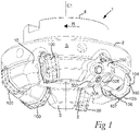
- Milling tools 1 according to a first embodiment and a second embodiment of the invention are shown in figs. 1-7 and figs. 8-11 , respectively. Common elements of the milling tool 1 according to the first and the second embodiment will in the following be described using common reference numerals.
- the milling tool 1 is in both embodiments a face milling tool and has a tool body 2 with a front end 3 and a rear end 4, between which a central axis C1 of rotation and a peripheral envelope surface 5 extend.
- a plurality of identical insert seats 6 are formed in a transition between the front end 3 and the peripheral envelope surface 5.
- Each insert seat 6 is configured to receive and support an indexable primary cutting insert 100 adapted to be detachably mounted therein by means of a screw 7.
- a bottom contact surface 8 and two side contact surfaces 9a, 9b are provided in each seat 6 for supporting the primary cutting insert 100 when mounted in the tool body 2.
- a chip pocket 10 is provided in front of each seat in a direction of rotation R of the tool body 2.
- each indexable primary cutting insert 100 is single-sided with a polygonal basic shape and comprises an upper side 101 and a lower side 102 between which a centre axis C2 extends as shown in fig. 4 .
- the upper side 101 and the lower side 102 are connected by a peripheral side surface 103.
- a cutting edge 104 comprising seven identical and alternately usable main cutting edges 105 configured for a main chip removing machining during face milling.
- the primary cutting insert has a total of seven index positions.
- the cutting edge 104 also comprises two secondary cutting edges 106, 107 configured for, depending on the entering angle ⁇ (see fig.
- the entering angle ⁇ is approximately 42°, in which case the secondary cutting edge 107 acts as a surface-wiping edge, while the secondary cutting edge 106 acts as a corner chamfer edge.
- the lower side 102 of the primary cutting insert 100 shown in fig. 10b , comprises a planar bottom support surface 108 configured to be supported by the bottom contact surface 8 of the insert seat 6 of the tool body 2.
- the peripheral side surface 103 of the primary cutting insert 100 comprises, for each index position, two side support surfaces 109a, 109b which rest against the side contact surfaces 9a, 9b of the insert seat 6 when the primary cutting insert 100 is mounted in the tool body 2. This can be seen in fig. 7 and figs. 12a-12c .
- the side contact surfaces 9a, 9b are also shown in fig. 2 , in which these surfaces have been highlighted by means of hatching.
- a cassette 200 is mounted instead of a primary cutting insert 100.
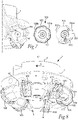
- the cassette used in the milling tool 1 according to the first embodiment is shown in fig. 5-6
- the cassette used in the milling tool according to the second embodiment is shown in fig. 9 .
- the cassette 200 is configured to be mounted in the same insert seats 6 as the primary cutting inserts 100 and therefore has similar dimensions.
- the cassette 200 is mounted using a screw 7.
- the cassette 200 has in both embodiments an upper side 201 and a lower side 202, between which a peripheral side surface 203 and a central axis C3 extend.
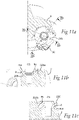
- the lower side 202 of the cassette 200 includes a bottom support surface 208 configured to rest against the bottom contact surface 8 of the insert seat 6 of the tool body 2, thus providing support for the cassette 200 in the tangential direction being parallel to the direction of rotation of the milling tool 1 such as shown in figs. 11a-11c .
- the bottom support surface 208 therefore has the same dimension and form as the bottom support surface 108 of the primary cutting inserts 100 as can be seen in figs. 10a-10b , and an interface between the bottom contact surface 8 and each of the bottom support surfaces 108, 208 is identical.
- the cassette 200 further has two side support surfaces 209a, 209b formed in the peripheral side surface 203, together configured to support the cassette 200 in the axial and radial directions of the milling tool 1. Since the cassette 200 is configured to be mounted in any one of the insert seats 6 of the tool body 2, the side support surfaces 209a, 209b have the same dimension and form as the side support surfaces 109a, 109b of the primary cutting inserts 100, such that an interface between the side contact surface 9a of the seat 6 and each of the side support surfaces 109a, 209a is identical as can be seen by comparing figs. 11a-11c to figs. 12a-12c .
- the interface between the side contact surface 9b of the insert seat 6 and each of the side support surfaces 109b, 209b is identical.
- the side and bottom contact surfaces of the tool body and/or the side and bottom support surfaces of the cassette and the primary cutting insert, respectively, may of course be designed in different ways, as long as the primary cutting insert and the cassette can be supported by the same contact surfaces of the tool body such that they can be exchangeably mounted in the same insert seat of the tool body.
- an insert seat 204 configured to support a secondary cutting insert 300 in the form of a wiper insert is formed in a transition between the upper side 201 and the peripheral side surface 203 of the cassette 200.
- the insert seat 204 is formed as a recess in the upper side 201 and the peripheral side surface 203 of the cassette 200, so that the secondary cutting insert 300 is entirely supported by the cassette 200 and, when mounted, is not in contact with the tool body 2.
- the secondary cutting insert 300 is in this embodiment a wiper insert mounted in the insert seat 204 using a screw 11. It has a rhombic basic shape and is single-sided with two index positions, thus having a positive cutting geometry with an upper side 301, a lower side 302 and a side surface 303 extending there between.
- a cutting edge 304 comprising two main cutting edges 305 configured for main chip removing machining and two wiper edges 306 for generating a smooth surface is formed in a transition between the upper side 301 and the side surface 303.
- the active main cutting edge 305 of the secondary cutting insert 300 is configured to enter the workpiece at an entering angle ⁇ which is the same as for the active main cutting edges 105 of the primary cutting inserts 100.
- the main cutting edge 305 of the secondary cutting insert 300 therefore has the same function as the main cutting edges 105 of the primary cutting inserts 100.
- the wiper edge 306 is however much longer than the surface-wiping edges 107 of the primary cutting inserts 100 and is also slightly curved (i.e. including a large wiper edge radius as known in the prior art). The wiper edge 306 therefore efficiently removes irregularities from the surface of the workpiece such that a smooth surface is generated during face milling.
- the cassette 200 has a first insert seat 205 and a second insert seat 206 formed in the transition between its upper side 201 and its peripheral side surface 203, i.e. a total of two insert seats 205, 206.
- the first insert seat 205 which when mounted in the milling tool 1 is positioned radially inside of the second insert seat 206, is configured to receive and support a secondary cutting insert 400 in the form of a ramping insert mounted using a screw 11.
- the second insert seat 206 is configured to receive and support another secondary cutting insert 500 having a main cutting edge 505 configured for chip removing machining at an entering angle ⁇ which is the same as for the active main cutting edges 105 of the primary cutting inserts 100.
- the secondary cutting insert 400 in the form of a ramping insert has a round basic shape and is single-sided, thus having a positive cutting geometry with an upper side 401, a lower side 402 and a side surface 403 extending there between.
- a circular cutting edge 404 is formed in a transition between the upper side 401 and the side surface 403.
- the positive cutting geometry provides a relatively large clearance behind the cutting edge 404, so that the secondary cutting insert 400 can be used for cutting during a ramping operation of the milling tool 1.
- the other secondary cutting insert 500 is mounted in the insert seat 206 using a screw 11 and is identical to the secondary cutting insert 300 shown in fig. 5 , but it is mounted in a different position and is used differently. It has a rhombic basic shape and is single-sided with two index positions, thus having a positive cutting geometry with an upper side 501, a lower side 502 and a side surface 503 extending there between.
- a cutting edge 504 comprising two main cutting edges 505 configured for main chip removing machining is formed in a transition between the upper side 501 and the side surface 503.
- this secondary cutting insert 500 is exclusively used for chip removing machining together with the primary cutting inserts 100.
- the cassette 200 is in both of the shown embodiments adjustable by means of a positioning screw 12.
- the cassette 200 is for this purpose divided into a major portion 210 and a minor portion 211. Between the minor portion 211 and the major portion 210, a hole 212 for receiving the positioning screw 12 is provided. Two grooves 213, 214 are formed in the upper side 201 of the cassette 200 between the hole 212 and the peripheral side surface 203, thus separating the major portion 210 from the minor portion 211.
- the major portion 210 of the cassette 200 comprises the insert seat 204 or insert seats 205, 206, while the minor portion 211 comprises the outermost side support surface 209a.
- a turning of the positioning screw 12 in hole 212 adjusts the position of the cassette 200 within the insert seat 6 of the tool body 2 by adjusting the distance between the major portion 210 and the minor portion 211 of the cassette 200.
- the width of the grooves 213, 214 increases upon tightening the positioning screw 12 into the hole 212 and vice versa, whereby the distance between the major and minor portions 210, 211 of the cassette 200 is adjusted.
- the cassette 200 has an inherent elasticity suitably provided by producing it in a steel material, whereby the grooves 213, 214 provide an elastic deformation, so that the distance is adjusted when operating the positioning screw 12. This is particularly relevant when two or more cassettes 200 with wiper inserts, e.g. according to the first embodiment shown in figs. 5-6 , are mounted in the tool body 2, in which case the wiper edges 306 may require individual adjustment in order to be positioned at the same axial level at the front end 3 of the tool body 2.
- fastening means other than screws such as e.g. clamps, may be used for fastening the cassette, the primary cutting insert and the secondary cutting insert.
- the primary and secondary cutting inserts may further have a different shape than the shapes shown and described above, and may be cutting inserts having positive or negative cutting geometries depending on the application.
- the milling tool may further be configured for either right hand rotation or left hand rotation.
Landscapes
- Engineering & Computer Science (AREA)
- Mechanical Engineering (AREA)
- Milling Processes (AREA)
Description
- The present invention relates to a milling tool for chip removing machining according to the preamble of
claim 1 comprising a kit comprising a tool body and a cassette for the milling tool for chip removing machining. - The milling tool according to the invention may preferably be configured for face milling or shoulder milling, although it should not be regarded as limited to those applications.
- By a cassette, sometimes also referred to as a cartridge, is herein intended a device adapted to be mounted to a tool body and adapted to support a cutting insert both in a tangential direction parallel to the direction of rotation of the tool body and in axial as well as radial directions of the tool body.
- Milling tools of the above mentioned kind for chip removing machining of metal workpieces are generally composed of a rotatable tool body and a plurality of replaceable cutting inserts made of cemented carbide, ceramics, or other hard material, mounted in seats of the tool body. The cutting inserts are preferably indexable with a plurality of index positions to prolong the service life of the cutting inserts. In particular in face milling tools, one or two of a plurality of mutually identical chip removing cutting inserts may be replaced by wiper inserts, configured for forming a smoother surface finish on the workpiece surface. The wiper inserts have a relatively long wiper edge for achieving said surface finish, and therefore often have a different shape with fewer index positions than the other chip removing cutting inserts. In addition, the size of the wiper inserts may be relatively large in comparison with the other chip removing cutting inserts, so that the relatively long wiper edge projects further toward the surface of the workpiece than the cutting edges of the other cutting inserts, whereby the wiper edges are able to finish the machined surface of the workpiece and remove irregularities created during the face milling operation. Thus, the wiper inserts not only have fewer index positions, but may also require more hard material in the form of e.g. cemented carbide or ceramics for production of each wiper insert in comparison with the other chip removing cutting inserts. The wiper inserts thereby become less cost efficient in comparison with the other chip removing cutting inserts.
- Furthermore, for some applications and in particular for the milling of specific workpiece materials, it is required that the cutting edge is made of cubic boron nitride (CBN) or polycrystalline diamond (PCD). In these cases, a CBN or PCD tip is usually brazed or otherwise attached to a cemented carbide insert body. The number of index positions of such cutting inserts is typically also reduced in comparison with a single material cutting insert.
- In certain types of milling tools, in particular face milling tools, one or more cassettes are provided for mounting in cassette seats of the tool body. The cassette in turn holds a cutting or wiper insert mounted in an insert seat therein. The milling tool may be provided with several cassette seats, each configured to support an adjustable cassette in which the cutting or wiper insert is mounted. The position of the wiper insert can hereby be adjusted in relation to the other chip removing cutting inserts. The cassette can also provide versatility since the cassettes may be provided with different insert seats adapted to hold different types of cutting inserts, so that the same tool body can be used for different cutting inserts and in various milling applications.
-
EP3009216 discloses a milling tool according to the preamble ofclaim 1 in which the tool body is formed with two types of seats (i.e. insert seats and cassette seats). Hence, the first type of seat is adapted for directly receiving a cutting insert and the second type of seat is adapted for receiving a cassette in which a cutting insert is mounted. In this case, the cassette allows an axial adjustment of the cutting insert mounted therein for allowing surface finishing of the workpiece surface. - However, in the milling tools discussed above, the tool body is required to be formed with cassette seats which are relatively spacious, and the tool body is thereby weakened in comparison with a milling tool without cassettes.
- It is an objective of the present invention to provide a solution to the above mentioned problems, which solution increases versatility and cost efficiency in milling applications without compromising the strength of the tool body. Another objective is to provide a solution that can reduce the material costs, in particular for applications requiring a wiper edge or cutting edges of CBN or PCD.
- At least the first objective is, according to the invention, achieved by means of a milling tool for chip removing machining according to
claim 1. The milling tool comprises a kit comprising a tool body and a cassette for the milling tool. The at least one side support surface and the bottom support surface of the cassette are configured to be supported by the at least one side contact surface and the bottom contact surface, respectively, of any one of the identical insert seats of the tool body, so that the cassette is configured to be detachably mounted in any one of the identical insert seats. - Hence, the milling tool according to the invention allows an exchangeable mounting of cassettes and chip removing cutting inserts in the insert seats of the tool body. Accordingly, a cassette can be mounted in any one of the insert seats in the place of a chip removing cutting insert. Thus, the tool body can be made equally strong as a tool body configured to be used without cassettes. At the same time, it is possible to mount a cassette holding a different type of cutting insert in one or more of the insert seats of the tool body. The versatility of a milling tool comprising the tool body is thereby increased without compromising the strength of the tool body. In other words, the same tool body used for a rough face milling operation with identical chip removing cutting inserts mounted in all insert seats of the tool body can also be used for a finishing face milling operation with a wiper insert mounted in a cassette replacing at least one of the chip removing cutting inserts. The same tool body may also be provided with (improved) ramping capability by replacing at least one of the chip removing cutting inserts by a cassette in which a cutting insert with a cutting edge arranged for ramping is mounted. Furthermore, the insert seat of the cassette is much smaller than the insert seat of the tool body, so the cutting insert mounted therein is consequently also much smaller. Thus, a relatively small amount of hard material is needed for manufacturing this cutting insert and the cost is reduced, while the same functionality is achieved as in the case of a milling tool in which one of the chip removing cutting inserts is replaced by a special cutting insert such as a wiper insert or a ramping insert.
- In an embodiment not according to the invention the milling tool may also be used with cassettes mounted in all seats of the tool body. This may be advantageous for applications that require that the cutting edge is made of cubic boron nitride (CBN) or polycrystalline diamond (PCD), since the cutting inserts can be made smaller and the amount of cemented carbide needed to produce the cutting inserts is reduced. Hence, the CBN/PCD cutting inserts may in this case be produced as chip removing cutting inserts configured for mounting in insert seats of the cassettes.
- It is also possible to use different kinds of cassettes mounted in the insert seats of the tool body, wherein the different kinds of cassettes are provided with different insert seats for receiving different kinds of cutting inserts. For example, a plurality of cassettes configured to receive chip removing cutting inserts may be provided, and one or two other cassettes having a seat configured to receive a wiper insert or a ramping insert.
- The bottom contact surface of the insert seat of the tool body is configured to support the cassette or the cutting insert, whichever is mounted in the insert seat, in a tangential direction being parallel to the direction of rotation of the tool body about the central axis of rotation. The at least one side contact surface of the insert seat of the tool body is configured to support the cassette or the cutting insert in the axial and radial directions of the milling tool. Typically, the insert seat may however be provided with two side contact surfaces for said axial and radial support.
- The insert seat(s) of the cassette(s) is/are hereby positioned and configured so that a cutting edge of a cutting insert mounted therein is active during the relevant machining operation of the cutting insert. In other words, the insert seat(s) of the cassette is/are configured for receiving the relevant cutting insert and is/are positioned such that the (indexable) cutting edge of the relevant cutting insert is active in for instance roughing, surface finishing or ramping operations, respectively. For instance, a wiper insert and a ramping insert may be differently shaped and thereby arranged in differently configured seats, which are located in different positions on the cassette such that the cutting edges become active in surface wiping and ramping operations, respectively, when the cassette is mounted in the insert seat of the tool body.
- According to one embodiment, the cassette comprises two insert seats formed in the transition between the upper side and the side surface. In this embodiment, the cassette is very versatile and may be used with one or two cutting inserts mounted therein depending on the desired milling operation. For example, one of the insert seats may be configured to receive a cutting insert for a particular milling operation, such as ramping, while the other insert seat may be configured to receive a cutting insert for surface wiping or the main chip removing roughing operation.
- According to one embodiment, the cassette comprises a means for adjusting a position of the cassette within the insert seat of the tool body. The position of the cutting edge of a cutting insert mounted in the cassette can thereby be fine-tuned so that a desirable machining precision is achieved. If for instance the tool body is arranged for face milling including wiper insert(s) mounted in the cassette(s), the axial position of the wiper edge(s) can be adjusted to a desired position in relation to the cutting edges of the other cutting inserts. This is also particularly advantageous if two or more cassettes are configured to receive wiper inserts, which are mounted in the tool body, in which case the two or more wiper edges may need individual adjustment in order to be situated at the same axial level for achieving a smooth surface finish and an even wear between all the wiper inserts. A cassette without the means for adjusting the position of the cassette within the insert seat may however be used in the case when only one cassette for receiving a wiper insert is mounted in the tool body, and/or in any case when the exact relative position between the cutting edges are non-crucial, such as when the cassette(s) is/are configured to receive a cutting insert for ramping.
- According to one embodiment, the means for adjusting a position comprises a positioning screw and a hole for receiving the positioning screw between a major portion and a minor portion of the cassette, the major and minor portions being separated by two grooves extending between the hole and the peripheral side surface of the cassette, so that the means for adjusting the position is adapted to, upon turning of the positioning screw in the hole, adjust a distance between the major portion and the minor portion of the cassette, wherein the minor portion comprises said side support surface of the cassette. This may preferably be the side support surface for supporting the cassette in the axial direction, so that the axial position of for instance a wiper edge can easily be adjusted by operating the positioning screw.
- According to one embodiment, the cassette is made of steel.
- Steel hereby provides a suitable inherent elasticity to allow an elastic deformation upon operating the above mentioned positioning screw for adjusting the distance between the minor and major portion of the cassette. The material cost of the cassette is furthermore relatively small in comparison with the material cost of a cutting insert which the cassette is replacing in the tool body. The overall cost of a milling tool in which the kit is used is thereby reduced.
- The milling tool for chip removing machining, comprises:
- a primary cutting insert comprising a cutting edge and being configured to be mounted in one of the identical insert seats of the tool body, wherein the primary cutting insert has a bottom support surface configured to be supported by the bottom contact surface of the insert seat and at least one side support surface configured to be supported by the at least one side contact surface of the insert seat when the primary cutting insert is mounted therein, and
- a secondary cutting insert comprising a cutting edge and being configured to be mounted in the at least one insert seat of the cassette,
- The milling tool according to the invention is advantageously a face milling tool or a shoulder milling tool. The primary cutting inserts are preferably indexable and may be single-sided but are preferably double-sided.
- According to one embodiment, the secondary cutting insert comprises a wiper edge, wherein the insert seat of the cassette is configured to receive the secondary cutting insert so that, when the cassette is mounted in the insert seat of the tool body, the wiper edge extends perpendicularly in relation to the central axis of rotation and is situated axially foremost at the front end of the milling tool for performing a surface finishing operation during face milling. Hence, the secondary cutting insert in this embodiment is a so called wiper insert. The wiper edge is relatively long and slightly curved (i.e. include a large radius of curvature as known surface wiping edges) and arranged to extend for said surface finishing of the workpiece surface. The face milling tool in this embodiment provides a cost efficient alternative to face milling tools in which one or two of the cutting inserts are replaced by wiper inserts adapted to be mounted directly in the insert seats of the tool body.
- According to one embodiment, the secondary cutting insert comprises a main cutting edge, wherein the insert seat of the cassette is configured to receive the secondary cutting insert so that, when the cassette is mounted in the insert seat of the tool body, the main cutting edge extends at an entering angle for a main chip removing machining operation. Hence, in a face milling tool, the secondary cutting insert in the form of a wiper insert may be formed with both a wiper edge and a main cutting edge configured for the main chip removing machining (roughing), i.e. peripheral chip removal at an entering angle to the surface of the workpiece. This increases the efficiency of the milling tool. This is also an advantageous embodiment in the case where CBN or PCD cutting edges are needed for chip removal.
- According to one embodiment, the secondary cutting insert comprises a ramping edge, wherein the insert seat of the cassette is configured to receive the secondary cutting insert so that, when the cassette is mounted in the insert seat of the tool body, the ramping edge extends along a radially inner portion of the insert seat for cutting during a ramping operation of the milling tool. This allows a face/shoulder milling tool to be used also for ramping operations, which is normally difficult due to insufficient clearance behind a surface generating cutting edge of the primary cutting inserts in such a tool. By replacing one of the primary cutting inserts with a cassette having a cutting insert with a ramping edge mounted therein, i.e., a cutting edge extending at an angle radially inwards in relation to the workpiece surface with a relatively large clearance behind it, a ramping operation is enabled. The ramping insert may e.g. be a round cutting insert with a positive cutting geometry.
- According to one embodiment, the cassette comprises two insert seats and the milling tool comprises two secondary cutting inserts, each mounted in one of the insert seats of the cassette. Two relatively small secondary cutting inserts optimised for different milling operations can thereby be provided, such as one ramping insert and one cutting insert comprising a main cutting edge configured for main chip removing machining (roughing). Of course, a cassette with two insert seats can also be used with only one cutting insert mounted in one of the insert seats.
- According to one embodiment, the secondary cutting insert is a single-sided indexable cutting insert with a positive cutting geometry. It is thereby possible to provide several alternately usable cutting edges having sufficient clearance behind the active cutting edge of the secondary cutting insert, regardless of whether the secondary cutting insert is a wiper insert or a ramping insert. The single-sided indexable secondary cutting insert configured as a wiper insert and/or a main chip removing (roughing) insert for a face milling operation may hereby preferably have a rhombic basic shape. A single-sided indexable secondary cutting insert configured for ramping may preferably have a round basic shape.
- According to one embodiment, the cutting edge of the secondary cutting insert comprises a portion made of cubic boron nitride (CBN) or polycrystalline diamond (PCD). The milling tool is thereby particularly suitable for specific workpiece materials or demanding applications requiring an edge with excellent hot hardness that can be used at high cutting speeds (CBN), or with excellent wear resistance (PCD). This is particularly advantageous if the cutting edge provided with a CBN or a PCD portion is a main cutting edge or a wiper edge. A milling tool may comprise several cassettes having such secondary cutting inserts mounted therein.
- According to one embodiment, the primary cutting insert is an indexable face milling insert having several indexable cutting edges, wherein each indexable cutting edge comprises a main cutting edge configured for a main chip removing machining operation and a secondary cutting edge configured for a surface finishing operation. The milling tool is thereby configured for efficient face milling.
- Further advantageous features and advantages of the invention will appear from the following detailed description.
- Embodiments of the invention will in the following be described by means of non-limiting examples with reference to the appended drawings, in which:
- Fig. 1
- is a perspective view showing a milling tool according to a first embodiment of the invention,
- Fig. 2
- is a front end view of the milling tool in
fig. 1 , - Fig. 3
- is a side view of the milling tool in
fig. 1 , - Fig. 4
- is a perspective view of a cutting insert used in the milling tool in
fig. 1 , - Fig. 5
- is an exploded view of a cassette and a cutting insert used in the milling tool in
fig. 1 , - Fig. 6
- is a top view of the cassette in
fig. 5 , - Fig. 7
- shows parts of the milling tool in
fig. 1 , - Fig. 8
- is a perspective view showing a milling tool according to a second embodiment of the invention,
- Fig. 9
- is an exploded view of a cassette and cutting inserts used in the milling tool in
fig. 8 , - Fig. 10a
- is a perspective view of the cassette and cutting inserts in
fig. 9 , - Fig. 10b
- is a perspective view of the cutting insert shown in
fig. 4 , - Fig. 11a
- is a perspective partial view of the milling tool in
fig. 8 , - Fig. 11b
- is a cross sectional view along the line Xlb-Xlb in
fig. 11a , - Fig. 11c
- is a cross sectional view along the line Xlc-Xlc in
fig. 11a , - Fig. 12a
- is a perspective view of a part of the milling tool which is common for both embodiments,
- Fig. 12b
- is a cross sectional view along the line XIIb-XIIb in
fig. 12a , and - Fig. 12c
- is a cross sectional view along the line Xllc-Xllc in
fig. 12a . -
Milling tools 1 according to a first embodiment and a second embodiment of the invention are shown infigs. 1-7 andfigs. 8-11 , respectively. Common elements of themilling tool 1 according to the first and the second embodiment will in the following be described using common reference numerals. - The
milling tool 1 is in both embodiments a face milling tool and has atool body 2 with afront end 3 and arear end 4, between which a central axis C1 of rotation and aperipheral envelope surface 5 extend. A plurality ofidentical insert seats 6 are formed in a transition between thefront end 3 and theperipheral envelope surface 5. Eachinsert seat 6 is configured to receive and support an indexableprimary cutting insert 100 adapted to be detachably mounted therein by means of ascrew 7. Abottom contact surface 8 and twoside contact surfaces seat 6 for supporting theprimary cutting insert 100 when mounted in thetool body 2. Achip pocket 10 is provided in front of each seat in a direction of rotation R of thetool body 2. - In both of the shown embodiments, each indexable
primary cutting insert 100 is single-sided with a polygonal basic shape and comprises anupper side 101 and alower side 102 between which a centre axis C2 extends as shown infig. 4 . Theupper side 101 and thelower side 102 are connected by aperipheral side surface 103. In a transition between theupper side 101 and theperipheral side surface 103, acutting edge 104 comprising seven identical and alternately usablemain cutting edges 105 configured for a main chip removing machining during face milling. In other words, the primary cutting insert has a total of seven index positions. Thecutting edge 104 also comprises twosecondary cutting edges fig. 3 ), surface finishing of the workpiece surface during face milling. This is described in detail inEP2893995 . In the shown embodiment, the entering angle κ is approximately 42°, in which case thesecondary cutting edge 107 acts as a surface-wiping edge, while thesecondary cutting edge 106 acts as a corner chamfer edge. - The
lower side 102 of theprimary cutting insert 100, shown infig. 10b , comprises a planarbottom support surface 108 configured to be supported by thebottom contact surface 8 of theinsert seat 6 of thetool body 2. Theperipheral side surface 103 of theprimary cutting insert 100 comprises, for each index position, twoside support surfaces side contact surfaces insert seat 6 when theprimary cutting insert 100 is mounted in thetool body 2. This can be seen infig. 7 andfigs. 12a-12c . Theside contact surfaces fig. 2 , in which these surfaces have been highlighted by means of hatching. -
- In one of the
insert seats 6 of thetool body 2, acassette 200 is mounted instead of aprimary cutting insert 100. The cassette used in themilling tool 1 according to the first embodiment is shown infig. 5-6 , and the cassette used in the milling tool according to the second embodiment is shown infig. 9 . Thecassette 200 is configured to be mounted in thesame insert seats 6 as the primary cutting inserts 100 and therefore has similar dimensions. Like the primary cutting inserts 100, thecassette 200 is mounted using ascrew 7. - More precisely, the
cassette 200 has in both embodiments anupper side 201 and alower side 202, between which aperipheral side surface 203 and a central axis C3 extend. Thelower side 202 of thecassette 200 includes abottom support surface 208 configured to rest against thebottom contact surface 8 of theinsert seat 6 of thetool body 2, thus providing support for thecassette 200 in the tangential direction being parallel to the direction of rotation of themilling tool 1 such as shown infigs. 11a-11c . Thebottom support surface 208 therefore has the same dimension and form as thebottom support surface 108 of the primary cutting inserts 100 as can be seen infigs. 10a-10b , and an interface between thebottom contact surface 8 and each of the bottom support surfaces 108, 208 is identical. Thecassette 200 further has twoside support surfaces peripheral side surface 203, together configured to support thecassette 200 in the axial and radial directions of themilling tool 1. Since thecassette 200 is configured to be mounted in any one of theinsert seats 6 of thetool body 2, theside support surfaces side support surfaces side contact surface 9a of theseat 6 and each of theside support surfaces figs. 11a-11c tofigs. 12a-12c . Likewise, the interface between theside contact surface 9b of theinsert seat 6 and each of the side support surfaces 109b, 209b is identical. The side and bottom contact surfaces of the tool body and/or the side and bottom support surfaces of the cassette and the primary cutting insert, respectively, may of course be designed in different ways, as long as the primary cutting insert and the cassette can be supported by the same contact surfaces of the tool body such that they can be exchangeably mounted in the same insert seat of the tool body. - In the first embodiment shown in
figs. 5-6 , aninsert seat 204 configured to support asecondary cutting insert 300 in the form of a wiper insert is formed in a transition between theupper side 201 and theperipheral side surface 203 of thecassette 200. Theinsert seat 204 is formed as a recess in theupper side 201 and theperipheral side surface 203 of thecassette 200, so that thesecondary cutting insert 300 is entirely supported by thecassette 200 and, when mounted, is not in contact with thetool body 2. - The
secondary cutting insert 300 is in this embodiment a wiper insert mounted in theinsert seat 204 using ascrew 11. It has a rhombic basic shape and is single-sided with two index positions, thus having a positive cutting geometry with anupper side 301, alower side 302 and aside surface 303 extending there between. Acutting edge 304 comprising twomain cutting edges 305 configured for main chip removing machining and twowiper edges 306 for generating a smooth surface is formed in a transition between theupper side 301 and theside surface 303. - During machining of a workpiece, the active
main cutting edge 305 of thesecondary cutting insert 300 is configured to enter the workpiece at an entering angle κ which is the same as for the activemain cutting edges 105 of the primary cutting inserts 100. Themain cutting edge 305 of thesecondary cutting insert 300 therefore has the same function as themain cutting edges 105 of the primary cutting inserts 100. Thewiper edge 306 is however much longer than the surface-wipingedges 107 of the primary cutting inserts 100 and is also slightly curved (i.e. including a large wiper edge radius as known in the prior art). Thewiper edge 306 therefore efficiently removes irregularities from the surface of the workpiece such that a smooth surface is generated during face milling. - In the second embodiment shown in
fig. 9 and fig. 10a , thecassette 200 has afirst insert seat 205 and asecond insert seat 206 formed in the transition between itsupper side 201 and itsperipheral side surface 203, i.e. a total of twoinsert seats first insert seat 205, which when mounted in themilling tool 1 is positioned radially inside of thesecond insert seat 206, is configured to receive and support asecondary cutting insert 400 in the form of a ramping insert mounted using ascrew 11. Thesecond insert seat 206 is configured to receive and support anothersecondary cutting insert 500 having amain cutting edge 505 configured for chip removing machining at an entering angle κ which is the same as for the activemain cutting edges 105 of the primary cutting inserts 100. - The
secondary cutting insert 400 in the form of a ramping insert has a round basic shape and is single-sided, thus having a positive cutting geometry with anupper side 401, alower side 402 and aside surface 403 extending there between. Acircular cutting edge 404 is formed in a transition between theupper side 401 and theside surface 403. The positive cutting geometry provides a relatively large clearance behind thecutting edge 404, so that thesecondary cutting insert 400 can be used for cutting during a ramping operation of themilling tool 1. - The other
secondary cutting insert 500 is mounted in theinsert seat 206 using ascrew 11 and is identical to thesecondary cutting insert 300 shown infig. 5 , but it is mounted in a different position and is used differently. It has a rhombic basic shape and is single-sided with two index positions, thus having a positive cutting geometry with anupper side 501, alower side 502 and aside surface 503 extending there between. Acutting edge 504 comprising twomain cutting edges 505 configured for main chip removing machining is formed in a transition between theupper side 501 and theside surface 503. The part of thecutting edge 504 which was in the first embodiment used as a wiper edge is in this embodiment used as themain cutting edge 505, while the part of the cutting edge which was in the first embodiment used as the main cutting edge is in this embodiment inactive. Thus, thissecondary cutting insert 500 is exclusively used for chip removing machining together with the primary cutting inserts 100. - The
cassette 200 is in both of the shown embodiments adjustable by means of apositioning screw 12. Thecassette 200 is for this purpose divided into amajor portion 210 and aminor portion 211. Between theminor portion 211 and themajor portion 210, ahole 212 for receiving thepositioning screw 12 is provided. Twogrooves upper side 201 of thecassette 200 between thehole 212 and theperipheral side surface 203, thus separating themajor portion 210 from theminor portion 211. Themajor portion 210 of thecassette 200 comprises theinsert seat 204 or insertseats minor portion 211 comprises the outermostside support surface 209a. A turning of thepositioning screw 12 inhole 212 adjusts the position of thecassette 200 within theinsert seat 6 of thetool body 2 by adjusting the distance between themajor portion 210 and theminor portion 211 of thecassette 200. In other words, the width of thegrooves positioning screw 12 into thehole 212 and vice versa, whereby the distance between the major andminor portions cassette 200 is adjusted. Hence, thecassette 200 has an inherent elasticity suitably provided by producing it in a steel material, whereby thegrooves positioning screw 12. This is particularly relevant when two ormore cassettes 200 with wiper inserts, e.g. according to the first embodiment shown infigs. 5-6 , are mounted in thetool body 2, in which case the wiper edges 306 may require individual adjustment in order to be positioned at the same axial level at thefront end 3 of thetool body 2. - The invention is of course not limited to the embodiments disclosed, but may be varied and modified within the scope of the following claims. For instance, fastening means other than screws, such as e.g. clamps, may be used for fastening the cassette, the primary cutting insert and the secondary cutting insert. The primary and secondary cutting inserts may further have a different shape than the shapes shown and described above, and may be cutting inserts having positive or negative cutting geometries depending on the application. The milling tool may further be configured for either right hand rotation or left hand rotation. It is also possible to have a shim plate mounted below the primary cutting inserts and the cassettes, in which case the bottom support surface of each of the cassette and the cutting insert rests against an upper surface of the shim plate, which in turn has a lower surface resting against the bottom contact surface of the seat of the tool body.
Claims (12)
- A milling tool (1) for chip removing machining comprising a kit comprising a tool body (2) and at least one cassette (200) for the milling tool (1) for chip removing machining, wherein the tool body (2) comprises:- a front end (3) and a rear end (4), between which a central axis (C1) of rotation and a peripheral envelope surface (5) extend,- at least two identical insert seats (6) formed in a transition between the front end (3) and the peripheral envelope surface (5), wherein each insert seat (6) is configured to support a cutting insert (100) adapted to be mounted therein, a bottom contact surface (8) and at least one side contact surface (9a, 9b) being provided in each insert seat (6) for supporting a bottom support surface (108) and at least one side support surface (109a, 109b) of the cutting insert (100), respectively; andwherein the cassette (200) comprises:- an upper side (201),- a lower side (202) comprising a bottom support surface (208),- a peripheral side surface (203) extending between the upper side (201) and the lower side (202), wherein the peripheral side surface (203) comprises at least one side support surface (209a, 209b), and- at least one insert seat (204, 205, 206) configured to support a secondary cutting insert (300, 400, 500), the insert seat (204, 205, 206) of the cassette (200) being formed in a transition between the upper side (201) and the peripheral side surface (203),wherein the milling tool comprises a primary cutting insert (100) comprising a cutting edge (104) and being configured to be mounted in one of the identical insert seats (6) of the tool body (2), wherein the primary cutting insert (100) has a bottom support surface (108) configured to be supported by the bottom contact surface (8) of the insert seat (6) and at least one side support surface (109a, 109b) configured to be supported by the at least one side contact surface (9a, 9b) of the insert seat (6) when the primary cutting insert (100) is mounted therein, anda secondary cutting insert (300, 400, 500) comprising a cutting edge (304, 404, 504) and being configured to be mounted in the at least one insert seat (204, 205, 206) of the cassette (200), characterized in thatthe at least one side support surface (209a, 209b) and the bottom support surface (208) of the cassette (200) are configured to be supported by the at least one side contact surface (9a, 9b) and the bottom contact surface (8), respectively, of any one of the identical insert seats (6) of the tool body (2), so that the cassette (200) is configured to be detachably mounted in any one of the identical insert seats (6) of the tool body (2).
- The milling tool according to claim 1, wherein the cassette (200) comprises two insert seats (205, 206) formed in the transition between the upper side (201) and the side surface (203).
- The milling tool according to claim 1 or 2, wherein the cassette (200) comprises a means for adjusting a position of the cassette (200) within the insert seat (6) of the tool body (2).
- The milling tool according to claim 3, wherein the means for adjusting a position comprises a positioning screw (12) and a hole (212) for receiving the positioning screw (12) between a major portion (210) and a minor portion (211) of the cassette (200), the major and minor portions (210, 211) being separated by two grooves (213, 214) extending between the hole (212) and the peripheral side surface (203) of the cassette (200), so that the means for adjusting the position is adapted to, upon turning of the positioning screw (12) in the hole (212), adjust a distance between the major portion (210) and the minor portion (211) of the cassette (200), wherein the minor portion (211) comprises said side support surface (209a, 209b) of the cassette (200).
- The milling tool according to any one of the preceding claims, wherein the cassette (200) is made of steel.
- The milling tool according to any one of the preceding claims, wherein the secondary cutting insert (300) comprises a wiper edge, and wherein the insert seat (204) of the cassette (200) is configured to receive the secondary cutting insert (300) so that, when the cassette (200) is mounted in the insert seat (6) of the tool body (2), the wiper edge (306) extends perpendicularly in relation to the central axis of rotation (C1) and is situated axially foremost at the front end (3) of the milling tool (1) for performing a surface finishing operation during face milling.
- The milling tool according to any one of the preceding claims, wherein the secondary cutting insert (300) comprises a main cutting edge (305, 505), and wherein the insert seat (204, 206) of the cassette (200) is configured to receive the secondary cutting insert (300) so that, when the cassette is mounted in the insert seat (6) of the tool body (2), the main cutting edge (305, 505) extends at an entering angle (κ) for a main chip removing machining operation.
- The milling tool according to any one of claims 1 - 5, wherein the secondary cutting insert (400) comprises a ramping edge (404), and wherein the insert seat (204, 206) of the cassette (200) is configured to receive the secondary cutting insert (400) so that, when the cassette is mounted in the insert seat (6) of the tool body (2), the ramping edge (404) extends along a radially inner portion of the insert seat (6) for cutting during a ramping operation of the milling tool (1).
- The milling tool according to any one of the preceding claims, wherein the cassette (200) comprises two insert seats (205, 206) and wherein the milling tool (1) comprises two secondary cutting inserts (400, 500), each mounted in one of the insert seats (205, 206) of the cassette (200).
- The milling tool according to any one of the preceding claims, wherein the secondary cutting insert (300, 400, 500) is a single-sided indexable cutting insert (300, 400, 500) with a positive cutting geometry.
- The milling tool according to any one of the preceding claims, wherein the cutting edge (304, 404, 504) of the secondary cutting insert (300, 400, 500) comprises a portion made of cubic boron nitride or polycrystalline diamond.
- The milling tool according to any one of the preceding claims, wherein the primary cutting insert (100) is an indexable face milling insert having several indexable cutting edges, wherein each indexable cutting edge comprises a main cutting edge (105) configured for a main chip removing machining operation and a secondary cutting edge (106, 107) configured for surface finishing operation.
Priority Applications (4)
| Application Number | Priority Date | Filing Date | Title |
|---|---|---|---|
| EP17160524.9A EP3375552B1 (en) | 2017-03-13 | 2017-03-13 | Milling tool comprising a kit for the milling tool |
| CN201880013983.9A CN110337342B (en) | 2017-03-13 | 2018-01-04 | Kit for a milling tool and a milling tool |
| PCT/EP2018/050193 WO2018166665A1 (en) | 2017-03-13 | 2018-01-04 | A kit for a milling tool and a milling tool |
| US16/493,439 US11376674B2 (en) | 2017-03-13 | 2018-01-04 | Kit for a milling tool and a milling tool |
Applications Claiming Priority (1)
| Application Number | Priority Date | Filing Date | Title |
|---|---|---|---|
| EP17160524.9A EP3375552B1 (en) | 2017-03-13 | 2017-03-13 | Milling tool comprising a kit for the milling tool |
Publications (2)
| Publication Number | Publication Date |
|---|---|
| EP3375552A1 EP3375552A1 (en) | 2018-09-19 |
| EP3375552B1 true EP3375552B1 (en) | 2022-12-21 |
Family
ID=58267007
Family Applications (1)
| Application Number | Title | Priority Date | Filing Date |
|---|---|---|---|
| EP17160524.9A Active EP3375552B1 (en) | 2017-03-13 | 2017-03-13 | Milling tool comprising a kit for the milling tool |
Country Status (4)
| Country | Link |
|---|---|
| US (1) | US11376674B2 (en) |
| EP (1) | EP3375552B1 (en) |
| CN (1) | CN110337342B (en) |
| WO (1) | WO2018166665A1 (en) |
Families Citing this family (1)
| Publication number | Priority date | Publication date | Assignee | Title |
|---|---|---|---|---|
| EP4015122B1 (en) * | 2020-12-21 | 2023-08-02 | Seco Tools Ab | Face milling cutter |
Family Cites Families (33)
| Publication number | Priority date | Publication date | Assignee | Title |
|---|---|---|---|---|
| FR1362568A (en) * | 1963-04-19 | 1964-06-05 | Stora Kopparbergs Bergslags Ab | Milling cutter |
| US4470731A (en) * | 1981-07-08 | 1984-09-11 | General Electric Company | Milling cutter with adjustable finishing insert |
| US4600341A (en) * | 1984-02-21 | 1986-07-15 | Board Harry B | Pocket reducing insert for toolholder and the like |
| SE501915C2 (en) * | 1993-03-18 | 1995-06-19 | Sandvik Ab | Fine cutter with recesses for axially adjustable cassettes |
| DK0830229T3 (en) * | 1995-06-06 | 2001-01-08 | Kennametal Inc | High speed cutter with cassettes |
| RU2076789C1 (en) * | 1995-07-11 | 1997-04-10 | Сурен Феликсович Аслибекян | Device for fastening cutting plates in assembled cutting tool |
| SE512736C2 (en) * | 1997-06-10 | 2000-05-08 | Seco Tools Ab | Face Milling Tools |
| CA2531425C (en) * | 2003-07-09 | 2011-09-06 | Kennametal Widia Produktions Gmbh & Co. Kg | Cutting insert |
| CN2748210Y (en) * | 2004-11-12 | 2005-12-28 | 哈尔滨量具刃具集团有限责任公司 | Interlocking tooth face milling cutter capable of toe index |
| US7878738B2 (en) * | 2005-05-21 | 2011-02-01 | Keenametal Inc. | Milling cutter and a cutting insert for a milling cutter |
| SE529108C2 (en) * | 2005-09-28 | 2007-05-02 | Seco Tools Ab | Milling and turning inserts for chip separating machining with cutting edges located lower a support surface |
| JP4491404B2 (en) * | 2005-11-07 | 2010-06-30 | 住友電工ハードメタル株式会社 | Tip changeable insert and tip changeable corner milling cutter |
| US7357604B2 (en) * | 2006-06-20 | 2008-04-15 | Kennametal Inc. | Indexable cutting insert with positive axial rake angle and multiple cutting edges |
| JP2009095894A (en) * | 2007-10-12 | 2009-05-07 | Sumitomo Electric Hardmetal Corp | Cutting edge adjusting mechanism and cutting tool using the same |
| US8454277B2 (en) * | 2008-12-18 | 2013-06-04 | Kennametal Inc. | Toolholder and toolholder assembly with elongated seating pads |
| IL200063A (en) * | 2009-07-26 | 2014-01-30 | Iscar Ltd | Cutting insert and rotary cutting tool |
| IL206272A (en) * | 2010-06-07 | 2014-08-31 | Iscar Ltd | Cutting insert and milling tool |
| US8449230B2 (en) * | 2010-08-13 | 2013-05-28 | Ingersoll Cutting Tool Company | Cutting insert having concave clearance depressions formed on corner side surfaces |
| IL210966A (en) * | 2011-01-31 | 2015-06-30 | Iscar Ltd | Tangential cutting insert and milling cutter |
| DE102011013812A1 (en) * | 2011-03-12 | 2012-09-13 | Kennametal Inc. | Tool for turn-turn-around or external milling |
| CN103442832A (en) * | 2011-04-25 | 2013-12-11 | 株式会社钨钛合金 | Cutting insert and indexable rotary cutting tool |
| DE102012102747A1 (en) * | 2012-03-29 | 2013-10-02 | Walter Ag | crankshaft cutters |
| US20140003872A1 (en) * | 2012-05-16 | 2014-01-02 | Kennametal Inc. | Cassette for a milling cutter |
| US9527142B2 (en) * | 2013-02-19 | 2016-12-27 | Iscar, Ltd. | High speed milling tool and tangential ramping milling insert therefor |
| EP2893997B1 (en) | 2014-01-08 | 2019-03-13 | Sandvik Intellectual Property AB | A milling tool |
| EP2893995B1 (en) | 2014-01-08 | 2019-03-27 | Sandvik Intellectual Property AB | A metal cutting insert and a milling tool |
| US10010953B2 (en) * | 2014-03-19 | 2018-07-03 | Kennametal Inc. | Wedge clamp and insert cartridge for cutting tool |
| US20160023288A1 (en) * | 2014-07-23 | 2016-01-28 | Kennametal Inc. | Cutting tool with shower cap |
| EP3009216B1 (en) | 2014-10-13 | 2020-05-06 | Sandvik Intellectual Property AB | Machining tool comprising a cutting insert positioning system |
| US10144071B2 (en) * | 2017-03-16 | 2018-12-04 | Iscar, Ltd. | Tool holder having position adjustment arrangement and cutting tool |
| CN112108697B (en) * | 2019-06-20 | 2024-08-06 | 肯纳金属印度有限公司 | Tool holder with pockets for receiving cutting inserts having different clearance angles |
| DE102020115987A1 (en) * | 2019-07-05 | 2021-01-07 | Kennametal India Limited | TWO-SIDED, POLYGONAL INDEXABLE INSERT WITH ALTERNATING CONCAVES AND CONVEX CUTTING EDGES |
| MX2021001665A (en) * | 2020-02-10 | 2021-09-10 | Decatur Diamond Llc | ROTARY CUTTING TOOL AND CARTRIDGE. |
-
2017
- 2017-03-13 EP EP17160524.9A patent/EP3375552B1/en active Active
-
2018
- 2018-01-04 US US16/493,439 patent/US11376674B2/en active Active
- 2018-01-04 CN CN201880013983.9A patent/CN110337342B/en not_active Expired - Fee Related
- 2018-01-04 WO PCT/EP2018/050193 patent/WO2018166665A1/en not_active Ceased
Also Published As
| Publication number | Publication date |
|---|---|
| CN110337342B (en) | 2021-04-20 |
| EP3375552A1 (en) | 2018-09-19 |
| US20200047262A1 (en) | 2020-02-13 |
| US11376674B2 (en) | 2022-07-05 |
| CN110337342A (en) | 2019-10-15 |
| WO2018166665A1 (en) | 2018-09-20 |
Similar Documents
| Publication | Publication Date | Title |
|---|---|---|
| EP3050655B1 (en) | A milling insert and a milling tool | |
| EP2101947B1 (en) | Cutting insert and cutting tool | |
| KR101704629B1 (en) | Replaceable-cutting-edge rotary cutting tool | |
| EP2070620B1 (en) | Cutting insert, cutting tool using the same, and cutting method | |
| KR101569551B1 (en) | Milling cutter and cutting insert therefor | |
| EP3266547B1 (en) | Cutting insert and cutting edge-replaceable rotary cutting tool | |
| CN110809502B (en) | Milling tool with replaceable cutting ring | |
| US7275895B2 (en) | Cutting insert | |
| US6619891B2 (en) | Milling tool having cutting members with different clearance angles | |
| JP5938868B2 (en) | Cutting insert and cutting edge changeable cutting tool | |
| JP2000308908A (en) | Cutting tools | |
| US20170120351A1 (en) | Double-sided cutting inserts with positive clearance face geometry | |
| WO2010027055A1 (en) | Side cutter | |
| CN110719821A (en) | Milling insert and three-edge milling cutter | |
| JP2008018515A (en) | Cutting insert and cutting tool | |
| EP3375552B1 (en) | Milling tool comprising a kit for the milling tool | |
| CN109715327B (en) | Face milling tool and its tangential cutting insert | |
| JP7131893B2 (en) | step milling cutter | |
| JP4940864B2 (en) | Throw-away rotary tool and tip mounted on it | |
| JP2026055843A (en) | Interchangeable tip milling tool and holder | |
| JP2026056015A (en) | Interchangeable tip milling tool and holder | |
| KR20250121025A (en) | Turning tools and cutting inserts for turning tools | |
| JP2007069306A (en) | Cutting tools and inserts | |
| JP2008142881A (en) | Insert detachable turning tool | |
| JP2019206062A (en) | Rotary cutting tool and chip parting member |
Legal Events
| Date | Code | Title | Description |
|---|---|---|---|
| PUAI | Public reference made under article 153(3) epc to a published international application that has entered the european phase |
Free format text: ORIGINAL CODE: 0009012 |
|
| STAA | Information on the status of an ep patent application or granted ep patent |
Free format text: STATUS: THE APPLICATION HAS BEEN PUBLISHED |
|
| AK | Designated contracting states |
Kind code of ref document: A1 Designated state(s): AL AT BE BG CH CY CZ DE DK EE ES FI FR GB GR HR HU IE IS IT LI LT LU LV MC MK MT NL NO PL PT RO RS SE SI SK SM TR |
|
| AX | Request for extension of the european patent |
Extension state: BA ME |
|
| STAA | Information on the status of an ep patent application or granted ep patent |
Free format text: STATUS: REQUEST FOR EXAMINATION WAS MADE |
|
| 17P | Request for examination filed |
Effective date: 20190319 |
|
| RBV | Designated contracting states (corrected) |
Designated state(s): AL AT BE BG CH CY CZ DE DK EE ES FI FR GB GR HR HU IE IS IT LI LT LU LV MC MK MT NL NO PL PT RO RS SE SI SK SM TR |
|
| GRAP | Despatch of communication of intention to grant a patent |
Free format text: ORIGINAL CODE: EPIDOSNIGR1 |
|
| STAA | Information on the status of an ep patent application or granted ep patent |
Free format text: STATUS: GRANT OF PATENT IS INTENDED |
|
| INTG | Intention to grant announced |
Effective date: 20220829 |
|
| GRAS | Grant fee paid |
Free format text: ORIGINAL CODE: EPIDOSNIGR3 |
|
| GRAA | (expected) grant |
Free format text: ORIGINAL CODE: 0009210 |
|
| STAA | Information on the status of an ep patent application or granted ep patent |
Free format text: STATUS: THE PATENT HAS BEEN GRANTED |
|
| AK | Designated contracting states |
Kind code of ref document: B1 Designated state(s): AL AT BE BG CH CY CZ DE DK EE ES FI FR GB GR HR HU IE IS IT LI LT LU LV MC MK MT NL NO PL PT RO RS SE SI SK SM TR |
|
| REG | Reference to a national code |
Ref country code: GB Ref legal event code: FG4D |
|
| REG | Reference to a national code |
Ref country code: CH Ref legal event code: EP |
|
| REG | Reference to a national code |
Ref country code: DE Ref legal event code: R096 Ref document number: 602017064727 Country of ref document: DE |
|
| REG | Reference to a national code |
Ref country code: AT Ref legal event code: REF Ref document number: 1538746 Country of ref document: AT Kind code of ref document: T Effective date: 20230115 |
|
| REG | Reference to a national code |
Ref country code: IE Ref legal event code: FG4D |
|
| REG | Reference to a national code |
Ref country code: LT Ref legal event code: MG9D |
|
| REG | Reference to a national code |
Ref country code: NL Ref legal event code: MP Effective date: 20221221 |
|
| PG25 | Lapsed in a contracting state [announced via postgrant information from national office to epo] |
Ref country code: SE Free format text: LAPSE BECAUSE OF FAILURE TO SUBMIT A TRANSLATION OF THE DESCRIPTION OR TO PAY THE FEE WITHIN THE PRESCRIBED TIME-LIMIT Effective date: 20221221 Ref country code: NO Free format text: LAPSE BECAUSE OF FAILURE TO SUBMIT A TRANSLATION OF THE DESCRIPTION OR TO PAY THE FEE WITHIN THE PRESCRIBED TIME-LIMIT Effective date: 20230321 Ref country code: LT Free format text: LAPSE BECAUSE OF FAILURE TO SUBMIT A TRANSLATION OF THE DESCRIPTION OR TO PAY THE FEE WITHIN THE PRESCRIBED TIME-LIMIT Effective date: 20221221 Ref country code: FI Free format text: LAPSE BECAUSE OF FAILURE TO SUBMIT A TRANSLATION OF THE DESCRIPTION OR TO PAY THE FEE WITHIN THE PRESCRIBED TIME-LIMIT Effective date: 20221221 |
|
| REG | Reference to a national code |
Ref country code: AT Ref legal event code: MK05 Ref document number: 1538746 Country of ref document: AT Kind code of ref document: T Effective date: 20221221 |
|
| PG25 | Lapsed in a contracting state [announced via postgrant information from national office to epo] |
Ref country code: RS Free format text: LAPSE BECAUSE OF FAILURE TO SUBMIT A TRANSLATION OF THE DESCRIPTION OR TO PAY THE FEE WITHIN THE PRESCRIBED TIME-LIMIT Effective date: 20221221 Ref country code: LV Free format text: LAPSE BECAUSE OF FAILURE TO SUBMIT A TRANSLATION OF THE DESCRIPTION OR TO PAY THE FEE WITHIN THE PRESCRIBED TIME-LIMIT Effective date: 20221221 Ref country code: HR Free format text: LAPSE BECAUSE OF FAILURE TO SUBMIT A TRANSLATION OF THE DESCRIPTION OR TO PAY THE FEE WITHIN THE PRESCRIBED TIME-LIMIT Effective date: 20221221 Ref country code: GR Free format text: LAPSE BECAUSE OF FAILURE TO SUBMIT A TRANSLATION OF THE DESCRIPTION OR TO PAY THE FEE WITHIN THE PRESCRIBED TIME-LIMIT Effective date: 20230322 |
|
| PG25 | Lapsed in a contracting state [announced via postgrant information from national office to epo] |
Ref country code: NL Free format text: LAPSE BECAUSE OF FAILURE TO SUBMIT A TRANSLATION OF THE DESCRIPTION OR TO PAY THE FEE WITHIN THE PRESCRIBED TIME-LIMIT Effective date: 20221221 |
|
| P01 | Opt-out of the competence of the unified patent court (upc) registered |
Effective date: 20230603 |
|
| PG25 | Lapsed in a contracting state [announced via postgrant information from national office to epo] |
Ref country code: SM Free format text: LAPSE BECAUSE OF FAILURE TO SUBMIT A TRANSLATION OF THE DESCRIPTION OR TO PAY THE FEE WITHIN THE PRESCRIBED TIME-LIMIT Effective date: 20221221 Ref country code: RO Free format text: LAPSE BECAUSE OF FAILURE TO SUBMIT A TRANSLATION OF THE DESCRIPTION OR TO PAY THE FEE WITHIN THE PRESCRIBED TIME-LIMIT Effective date: 20221221 Ref country code: PT Free format text: LAPSE BECAUSE OF FAILURE TO SUBMIT A TRANSLATION OF THE DESCRIPTION OR TO PAY THE FEE WITHIN THE PRESCRIBED TIME-LIMIT Effective date: 20230421 Ref country code: ES Free format text: LAPSE BECAUSE OF FAILURE TO SUBMIT A TRANSLATION OF THE DESCRIPTION OR TO PAY THE FEE WITHIN THE PRESCRIBED TIME-LIMIT Effective date: 20221221 Ref country code: EE Free format text: LAPSE BECAUSE OF FAILURE TO SUBMIT A TRANSLATION OF THE DESCRIPTION OR TO PAY THE FEE WITHIN THE PRESCRIBED TIME-LIMIT Effective date: 20221221 Ref country code: CZ Free format text: LAPSE BECAUSE OF FAILURE TO SUBMIT A TRANSLATION OF THE DESCRIPTION OR TO PAY THE FEE WITHIN THE PRESCRIBED TIME-LIMIT Effective date: 20221221 Ref country code: AT Free format text: LAPSE BECAUSE OF FAILURE TO SUBMIT A TRANSLATION OF THE DESCRIPTION OR TO PAY THE FEE WITHIN THE PRESCRIBED TIME-LIMIT Effective date: 20221221 |
|
| PG25 | Lapsed in a contracting state [announced via postgrant information from national office to epo] |
Ref country code: SK Free format text: LAPSE BECAUSE OF FAILURE TO SUBMIT A TRANSLATION OF THE DESCRIPTION OR TO PAY THE FEE WITHIN THE PRESCRIBED TIME-LIMIT Effective date: 20221221 Ref country code: PL Free format text: LAPSE BECAUSE OF FAILURE TO SUBMIT A TRANSLATION OF THE DESCRIPTION OR TO PAY THE FEE WITHIN THE PRESCRIBED TIME-LIMIT Effective date: 20221221 Ref country code: IS Free format text: LAPSE BECAUSE OF FAILURE TO SUBMIT A TRANSLATION OF THE DESCRIPTION OR TO PAY THE FEE WITHIN THE PRESCRIBED TIME-LIMIT Effective date: 20230421 Ref country code: AL Free format text: LAPSE BECAUSE OF FAILURE TO SUBMIT A TRANSLATION OF THE DESCRIPTION OR TO PAY THE FEE WITHIN THE PRESCRIBED TIME-LIMIT Effective date: 20221221 |
|
| REG | Reference to a national code |
Ref country code: DE Ref legal event code: R097 Ref document number: 602017064727 Country of ref document: DE |
|
| PLBE | No opposition filed within time limit |
Free format text: ORIGINAL CODE: 0009261 |
|
| STAA | Information on the status of an ep patent application or granted ep patent |
Free format text: STATUS: NO OPPOSITION FILED WITHIN TIME LIMIT |
|
| PG25 | Lapsed in a contracting state [announced via postgrant information from national office to epo] |
Ref country code: MC Free format text: LAPSE BECAUSE OF FAILURE TO SUBMIT A TRANSLATION OF THE DESCRIPTION OR TO PAY THE FEE WITHIN THE PRESCRIBED TIME-LIMIT Effective date: 20221221 Ref country code: DK Free format text: LAPSE BECAUSE OF FAILURE TO SUBMIT A TRANSLATION OF THE DESCRIPTION OR TO PAY THE FEE WITHIN THE PRESCRIBED TIME-LIMIT Effective date: 20221221 |
|
| REG | Reference to a national code |
Ref country code: CH Ref legal event code: PL |
|
| 26N | No opposition filed |
Effective date: 20230922 |
|
| REG | Reference to a national code |
Ref country code: BE Ref legal event code: MM Effective date: 20230331 |
|
| PG25 | Lapsed in a contracting state [announced via postgrant information from national office to epo] |
Ref country code: LU Free format text: LAPSE BECAUSE OF NON-PAYMENT OF DUE FEES Effective date: 20230313 |
|
| REG | Reference to a national code |
Ref country code: IE Ref legal event code: MM4A |
|
| PG25 | Lapsed in a contracting state [announced via postgrant information from national office to epo] |
Ref country code: SI Free format text: LAPSE BECAUSE OF FAILURE TO SUBMIT A TRANSLATION OF THE DESCRIPTION OR TO PAY THE FEE WITHIN THE PRESCRIBED TIME-LIMIT Effective date: 20221221 Ref country code: LI Free format text: LAPSE BECAUSE OF NON-PAYMENT OF DUE FEES Effective date: 20230331 Ref country code: IE Free format text: LAPSE BECAUSE OF NON-PAYMENT OF DUE FEES Effective date: 20230313 Ref country code: CH Free format text: LAPSE BECAUSE OF NON-PAYMENT OF DUE FEES Effective date: 20230331 |
|
| PG25 | Lapsed in a contracting state [announced via postgrant information from national office to epo] |
Ref country code: BE Free format text: LAPSE BECAUSE OF NON-PAYMENT OF DUE FEES Effective date: 20230331 |
|
| PGFP | Annual fee paid to national office [announced via postgrant information from national office to epo] |
Ref country code: DE Payment date: 20240130 Year of fee payment: 8 Ref country code: GB Payment date: 20240201 Year of fee payment: 8 |
|
| PGFP | Annual fee paid to national office [announced via postgrant information from national office to epo] |
Ref country code: IT Payment date: 20240212 Year of fee payment: 8 Ref country code: FR Payment date: 20240223 Year of fee payment: 8 |
|
| PG25 | Lapsed in a contracting state [announced via postgrant information from national office to epo] |
Ref country code: BG Free format text: LAPSE BECAUSE OF FAILURE TO SUBMIT A TRANSLATION OF THE DESCRIPTION OR TO PAY THE FEE WITHIN THE PRESCRIBED TIME-LIMIT Effective date: 20221221 |
|
| PG25 | Lapsed in a contracting state [announced via postgrant information from national office to epo] |
Ref country code: BG Free format text: LAPSE BECAUSE OF FAILURE TO SUBMIT A TRANSLATION OF THE DESCRIPTION OR TO PAY THE FEE WITHIN THE PRESCRIBED TIME-LIMIT Effective date: 20221221 |
|
| PG25 | Lapsed in a contracting state [announced via postgrant information from national office to epo] |
Ref country code: CY Free format text: LAPSE BECAUSE OF FAILURE TO SUBMIT A TRANSLATION OF THE DESCRIPTION OR TO PAY THE FEE WITHIN THE PRESCRIBED TIME-LIMIT; INVALID AB INITIO Effective date: 20170313 |
|
| PG25 | Lapsed in a contracting state [announced via postgrant information from national office to epo] |
Ref country code: HU Free format text: LAPSE BECAUSE OF FAILURE TO SUBMIT A TRANSLATION OF THE DESCRIPTION OR TO PAY THE FEE WITHIN THE PRESCRIBED TIME-LIMIT; INVALID AB INITIO Effective date: 20170313 |
|
| REG | Reference to a national code |
Ref country code: DE Ref legal event code: R119 Ref document number: 602017064727 Country of ref document: DE |
|
| GBPC | Gb: european patent ceased through non-payment of renewal fee |
Effective date: 20250313 |
|
| PG25 | Lapsed in a contracting state [announced via postgrant information from national office to epo] |
Ref country code: TR Free format text: LAPSE BECAUSE OF FAILURE TO SUBMIT A TRANSLATION OF THE DESCRIPTION OR TO PAY THE FEE WITHIN THE PRESCRIBED TIME-LIMIT Effective date: 20221221 |
|
| PG25 | Lapsed in a contracting state [announced via postgrant information from national office to epo] |
Ref country code: DE Free format text: LAPSE BECAUSE OF NON-PAYMENT OF DUE FEES Effective date: 20251001 |
|
| PG25 | Lapsed in a contracting state [announced via postgrant information from national office to epo] |
Ref country code: GB Free format text: LAPSE BECAUSE OF NON-PAYMENT OF DUE FEES Effective date: 20250313 |
|
| PG25 | Lapsed in a contracting state [announced via postgrant information from national office to epo] |
Ref country code: FR Free format text: LAPSE BECAUSE OF NON-PAYMENT OF DUE FEES Effective date: 20250331 Ref country code: IT Free format text: LAPSE BECAUSE OF NON-PAYMENT OF DUE FEES Effective date: 20250313 |