EP2893995A1 - A metal cutting insert and a milling tool - Google Patents
A metal cutting insert and a milling tool Download PDFInfo
- Publication number
- EP2893995A1 EP2893995A1 EP14150475.3A EP14150475A EP2893995A1 EP 2893995 A1 EP2893995 A1 EP 2893995A1 EP 14150475 A EP14150475 A EP 14150475A EP 2893995 A1 EP2893995 A1 EP 2893995A1
- Authority
- EP
- European Patent Office
- Prior art keywords
- cutting
- cutting edge
- cutting insert
- edge portion
- main
- Prior art date
- Legal status (The legal status is an assumption and is not a legal conclusion. Google has not performed a legal analysis and makes no representation as to the accuracy of the status listed.)
- Granted
Links
Images


Classifications
-
- B—PERFORMING OPERATIONS; TRANSPORTING
- B23—MACHINE TOOLS; METAL-WORKING NOT OTHERWISE PROVIDED FOR
- B23C—MILLING
- B23C5/00—Milling-cutters
- B23C5/16—Milling-cutters characterised by physical features other than shape
- B23C5/20—Milling-cutters characterised by physical features other than shape with removable cutter bits or teeth or cutting inserts
- B23C5/202—Plate-like cutting inserts with special form
- B23C5/205—Plate-like cutting inserts with special form characterised by chip-breakers of special form
-
- B—PERFORMING OPERATIONS; TRANSPORTING
- B23—MACHINE TOOLS; METAL-WORKING NOT OTHERWISE PROVIDED FOR
- B23C—MILLING
- B23C5/00—Milling-cutters
- B23C5/02—Milling-cutters characterised by the shape of the cutter
- B23C5/06—Face-milling cutters, i.e. having only or primarily a substantially flat cutting surface
-
- B—PERFORMING OPERATIONS; TRANSPORTING
- B23—MACHINE TOOLS; METAL-WORKING NOT OTHERWISE PROVIDED FOR
- B23C—MILLING
- B23C5/00—Milling-cutters
- B23C5/16—Milling-cutters characterised by physical features other than shape
- B23C5/20—Milling-cutters characterised by physical features other than shape with removable cutter bits or teeth or cutting inserts
- B23C5/202—Plate-like cutting inserts with special form
-
- B—PERFORMING OPERATIONS; TRANSPORTING
- B23—MACHINE TOOLS; METAL-WORKING NOT OTHERWISE PROVIDED FOR
- B23C—MILLING
- B23C2200/00—Details of milling cutting inserts
- B23C2200/04—Overall shape
- B23C2200/0488—Heptagonal
-
- B—PERFORMING OPERATIONS; TRANSPORTING
- B23—MACHINE TOOLS; METAL-WORKING NOT OTHERWISE PROVIDED FOR
- B23C—MILLING
- B23C2200/00—Details of milling cutting inserts
- B23C2200/12—Side or flank surfaces
- B23C2200/125—Side or flank surfaces discontinuous
-
- B—PERFORMING OPERATIONS; TRANSPORTING
- B23—MACHINE TOOLS; METAL-WORKING NOT OTHERWISE PROVIDED FOR
- B23C—MILLING
- B23C2200/00—Details of milling cutting inserts
- B23C2200/36—Other features of the milling insert not covered by B23C2200/04 - B23C2200/32
- B23C2200/365—Lands, i.e. the outer peripheral section of rake faces
-
- B—PERFORMING OPERATIONS; TRANSPORTING
- B23—MACHINE TOOLS; METAL-WORKING NOT OTHERWISE PROVIDED FOR
- B23C—MILLING
- B23C2210/00—Details of milling cutters
- B23C2210/04—Angles
- B23C2210/0407—Cutting angles
- B23C2210/0442—Cutting angles positive
- B23C2210/045—Cutting angles positive axial rake angle
-
- Y—GENERAL TAGGING OF NEW TECHNOLOGICAL DEVELOPMENTS; GENERAL TAGGING OF CROSS-SECTIONAL TECHNOLOGIES SPANNING OVER SEVERAL SECTIONS OF THE IPC; TECHNICAL SUBJECTS COVERED BY FORMER USPC CROSS-REFERENCE ART COLLECTIONS [XRACs] AND DIGESTS
- Y10—TECHNICAL SUBJECTS COVERED BY FORMER USPC
- Y10T—TECHNICAL SUBJECTS COVERED BY FORMER US CLASSIFICATION
- Y10T407/00—Cutters, for shaping
- Y10T407/19—Rotary cutting tool
- Y10T407/1906—Rotary cutting tool including holder [i.e., head] having seat for inserted tool
- Y10T407/1908—Face or end mill
- Y10T407/1924—Specified tool shape
-
- Y—GENERAL TAGGING OF NEW TECHNOLOGICAL DEVELOPMENTS; GENERAL TAGGING OF CROSS-SECTIONAL TECHNOLOGIES SPANNING OVER SEVERAL SECTIONS OF THE IPC; TECHNICAL SUBJECTS COVERED BY FORMER USPC CROSS-REFERENCE ART COLLECTIONS [XRACs] AND DIGESTS
- Y10—TECHNICAL SUBJECTS COVERED BY FORMER USPC
- Y10T—TECHNICAL SUBJECTS COVERED BY FORMER US CLASSIFICATION
- Y10T407/00—Cutters, for shaping
- Y10T407/23—Cutters, for shaping including tool having plural alternatively usable cutting edges
- Y10T407/235—Cutters, for shaping including tool having plural alternatively usable cutting edges with integral chip breaker, guide or deflector
Definitions
- the present invention relates to a cutting insert configured for chip-removing machining of a metallic workpiece by means of milling according to the preamble of claim 1.
- the present invention also relates to a milling tool according to the preamble of claim 14 comprising a tool body and at least one such cutting insert.
- Milling tools for chip-removing machining of metal workpieces are generally composed of a rotatable tool body and a plurality of replaceable cutting inserts made of cemented carbide, ceramics, or other hard material. Since the cutting inserts are subjected to significant wear upon use in a milling tool, it is desirable for the insert to have as many edges as possible in order to prolong the service life of the cutting insert. Cutting inserts are therefore often made double-sided with cutting edges formed along both an upper side and a lower side of the insert, thus doubling the number of cutting edges per insert.
- a face milling tool configured for chip-removing machining and a double-sided cutting insert with seven main cutting edges per side are disclosed in EP2022584 .
- the milling tool comprises a tool body including a front end and a rear end, between which a central rotation axis extends around which the tool is rotatable in a direction of rotation and with which an envelope surface is concentric.
- Several insert seats are formed in a transition between the front end and the envelope surface.
- Each insert seat comprises a bottom support surface and a side support comprising at least one side support surface.
- a chip pocket is provided in front of each insert seat in the direction of rotation of the tool.
- the tool further comprises several cutting inserts securely and detachably mounted in the insert seats.
- the cutting insert disclosed in EP2022584 comprises an upper side defining an upper extension plane and a lower side defining a lower extension plane parallel to the upper extension plane, wherein a centre axis extends perpendicularly through the upper extension plane and the lower extension plane.
- a side surface connects the upper side and the lower side, the side surface comprising a plurality of main and secondary clearance surfaces.
- Seven identical and alternately usable upper cutting edges extend around the upper side, wherein each cutting edge comprises a chip removing main cutting edge portion and a secondary cutting edge portion, wherein the main cutting edge portion is formed in a transition between the upper side and one of said main clearance surfaces, and the secondary cutting edge portion is formed in a transition between the upper side and one of said secondary clearance surfaces in a region between two main cutting edge portions.
- the milling insert has a conventional negative geometry with the clearance surfaces formed at right angles with respect to the upper and lower extension planes of the insert.
- the cutting insert is mounted in the tool body of the milling tool such that the main cutting edge is at a corner angle of 40°-44° with respect to the axis of rotation of the milling tool.
- the entering angle K between the main cutting edge and the direction of feed of the milling tool is 46°-50°.
- the cutting insert further has curved cutting edges, which serve to ensure a positive effective angle of inclination of the main cutting edge also for negative axial and moderately negative radial tipping-in angles (rake angles). This improves the chip formation properties of the tool for moderate cutting depths.
- each of said upper main clearance surfaces is formed at an obtuse inner angle with respect to the upper extension plane as seen in side elevation view.
- the upper main clearance surface is inclined outwards.
- the angle of inclination of the main cutting edge may be set to strongly positive in a milling tool configured such that the axial tipping-in angle, or axial rake angle, is neutral or negative, the radial tipping-in angle, or radial rake angle, is strongly negative, and the entering angle is acute.
- the milling tool With a strongly positive angle of inclination of the main cutting edge, the milling tool operates more smoothly since the main cutting edge portion gradually enters the workpiece, giving lower noise levels and an improved toughness behaviour of the cutting edges. Furthermore, the chip formation is excellent, giving spiral chips which are easily evacuated. Thanks to the possibility of having a large angle of inclination, the cutting insert according to the invention has cutting characteristics similar to a single-sided cutting insert with positive geometry and thereby with a large angle of inclination. Similar to such an insert, it is suitable for milling in stainless steel, such as duplex stainless steel. However, the negative geometry of the cutting insert according to the invention enables more cutting edges per cutting insert and therefore also a better tool economy than with a single-sided positive cutting insert.
- the inner angle ⁇ between the upper extension plane and each of said upper main clearance surfaces is within the range 93° ⁇ ⁇ ⁇ 118°.
- An angle smaller than 93° may result in a too large clearance between on one hand the main clearance surface located rotationally behind the chip-removing main cutting edge portion and on the other hand the generally cone-shaped surface generated by the same.
- a too large clearance reduces the strength of the cutting insert.
- An angle larger than 118° may instead give an insufficient clearance.
- the inner angle ⁇ is within the range 98° ⁇ ⁇ ⁇ 114°, in which range the clearance is optimised.
- the upper side comprises a recessed upper base surface extending in parallel with the upper extension plane, and an upper chip surface extending between the upper cutting edges and the upper base surface.
- the upper side further comprises at least one upper reinforcement land connecting the upper cutting edges with the upper chip surface.
- the at least one reinforcement land increases the main cutting edge angle, which is the inner angle between the upper main clearance surface and the chip surface as seen in cross section, and thereby increases the strength of the cutting edge.
- the reinforcement land also acts so as to guide the chip away from the chip surface, reducing friction and thereby also heat generation.
- This embodiment is particularly advantageous for working at high loads.
- the width and the angle of the reinforcement land may be varied, but generally a wider reinforcement land enables working at higher loads. It is also possible to have more than one reinforcement lands, for example two reinforcement lands which are arranged in connection to each other and at a slightly different angle with respect to the upper extension plane.
- each of said secondary clearance surfaces is formed at an inner angle ⁇ with respect to the upper extension plane as seen in side elevation view, wherein ⁇ ⁇ ⁇ .
- the inner angle ⁇ between the upper extension plane and the secondary clearance surface below at least a part of the upper secondary cutting edge is within the range 85° ⁇ ⁇ ⁇ 100°. Within this range, the clearance behind the secondary edge portion is optimised for neutral (0°) to slightly negative axial tipping-in angles.
- the cutting insert comprises at least seven identical and alternately usable upper cutting edges.
- the large number of cutting edges prolongs the service life of the cutting insert in comparison with a cutting insert with a smaller number of edges.
- the cutting insert is double-sided with the lower side identical to the upper side. This doubles the number of usable cutting edges and thus also doubles the service life in comparison with a single-sided cutting insert.
- the side surface comprises a plurality of recessed support surfaces. By making the support surfaces recessed, their length may be increased so that the total support surface area is increased.
- the recessed support surfaces which may be rounded or planar, thereby serve to improve the localisation of the cutting insert in an insert seat of a tool body when the cutting insert forms part of a milling tool, and to prevent rotation of the cutting insert within the insert seat.
- the main cutting edge portion is rectilinear or essentially rectilinear.
- Such a cutting insert generally gives better chip formation along the entire length of the main cutting edge portion than a cutting insert with a curved main cutting edge portion. Thereby, the same cutting insert can, without chip formation problems, be used for different cutting depths.
- the secondary cutting edge portion is in the form of a curved edge portion extending between two adjacent main cutting edge portions and having at least one radius of curvature.
- a cutting insert is useful for example for large cutting depths since the main cutting edge portion is relatively long compared to a cutting insert with surface-wiping secondary edges. It also has strong corner regions and may functionally give reduced cutting forces in comparison with cutting inserts with surface-wiping secondary edges. A larger radius of curvature of the curved edge portion gives a stronger corner region.
- the transitions between the secondary clearance surfaces and the main clearance surfaces is normally gradual, such that there is no sharp edge marking the transition.
- the secondary clearance surface is the surface portion rotationally behind the secondary cutting edge portion
- the main clearance surface is the surface portion rotationally behind the main cutting edge portion.
- the secondary cutting edge portion is in the form of at least one facetted edge portion formed between two adjacent main cutting edge portions.
- a facetted edge portion could for example serve as a corner generating edge portion.
- the at least one secondary cutting edge portion is in the form of a surface-wiping secondary edge.
- a cutting insert according to this embodiment may be used to generate planar surfaces and is preferably used for finishing operations.
- the angle that the surface-wiping secondary edge makes with the main cutting edge portion may be adapted for different entering angles of the milling tool.
- each upper cutting edge comprises a first and a second surface-wiping secondary edge formed at an angle with respect to each other as seen in plan view.
- the above mentioned object is achieved by the face milling tool initially defined, which is characterised in that the tool comprises at least one cutting insert according to the invention securely and detachably mounted in the at least one insert seat.
- the tool is configured so that a main cutting edge portion is at an entering angle K smaller than 80°, and so that the upper extension plane of the cutting insert is on one hand radially tipped in at a radial tipping-in angle ⁇ f within the range - 60° ⁇ ⁇ f ⁇ -25° and on the other hand axially tipped in at an axial tipping-in angle ⁇ m within the range -20° ⁇ ⁇ m ⁇ 0°.
- the cutting insert according to a first embodiment of the invention is shown in fig. 1-4 .
- the cutting insert 1 is double-sided with a polygonal basic shape and comprises an upper side 2 defining an upper extension plane P U and an identical lower side 3 defining a lower extension plane P L , which is parallel to the upper extension plane P U .
- a centre axis C2 extends perpendicularly through the upper extension plane P U and the lower extension plane P L .
- the upper side 2 and the lower side 3 are connected by a side surface 4, which comprises several main clearance surfaces 5, 15 and secondary clearance surfaces 6a, 6b, 16a, 16b.
- a side surface 4 which comprises several main clearance surfaces 5, 15 and secondary clearance surfaces 6a, 6b, 16a, 16b.
- Each cutting edge comprises an essentially rectilinear chip removing main cutting edge portion 8 and a first and a second secondary cutting edge portion 9, 10, formed as surface-wiping edges.
- the main cutting edge portion 8 is formed in a transition between the upper side 2 and one of the upper main clearance surfaces 5.
- the first secondary cutting edge portion 9 is formed in a transition between the upper side 2 and a first upper secondary clearance surface 6a in a region between two main cutting edge portions 8, that is, in a corner region of the cutting insert 1.
- the second secondary cutting edge portion 10 is formed in a transition between the upper side 2 and a second upper secondary clearance surface 6b.
- the first secondary cutting edge portion 9 is here configured to act as a surface-wiping secondary edge when the cutting insert 1 is mounted in a milling tool with an entering angle K of approximately 25°. If instead the cutting insert 1 is mounted in a milling tool with an entering angle K of approximately 42°, the first secondary cutting edge portion 9 acts as a corner edge, while the second secondary cutting edge portion 10 at this entering angle is configured to act as a surface-wiping secondary edge.
- the milling insert 1 according to this embodiment can be used for two different entering angles.
- the edge portions between the main cutting edge portion 8, the first secondary cutting edge portion 9, the second secondary cutting edge portion 10 and the next main cutting edge portion 8 are formed as radial transitions.
- the cutting insert 1 further comprises a recessed upper base surface 11 extending in parallel with the upper extension plane P U .
- An upper chip surface 12 extends in the region between the upper cutting edges 7 and the upper base surface 11. Furthermore, between the cutting edges 7 and the base surface 11, a reinforcement land 13 extends.
- the cutting insert 1 in this first embodiment also comprises, in its side surface 4, several recessed support surfaces 14 forming a "waist" around the cutting insert. As can be seen in fig. 4a and 4b , the radial distance measured from the centre axis C2 to the recessed support surface 14 below one of the main cutting edge portions 8 equals the radial distance from the centre axis C2 to the main cutting edge portion 8.
- the corresponding distance between the recessed support surface 14 and the centre axis C2 is smaller than the distance from the centre axis C2 to the secondary cutting edge portions 9, 10. Transition surfaces are formed between the recessed support surface 14 and the clearance surfaces 5, 6a, 6b.
- the main clearance surface 5 is formed at an obtuse inner angle ⁇ with respect to the upper extension plane P U as seen in side elevation view.
- a partial cross section taken across the main clearance surface shows the obtuse angle ⁇ .
- the inner angle ⁇ is 107°.
- the secondary clearance surfaces 6a, 6b are formed at inner angles ⁇ 1 , ⁇ 2 with respect to the upper extension plane P U as seen in side elevation view.
- the cutting insert 1 is indexable to different index positions.
- one of the upper cutting edges 7 is cutting, wherein the upper side 2 partially forms a rake surface and the lower side 3 forms a support surface resting on a bottom support surface of an insert seat of a milling tool.
- one of a number of lower cutting edges 17 extending around the lower side 3 is cutting, wherein the lower side 3 partially forms a rake surface, and the upper side 2 forms a support surface resting on the bottom support surface of the insert seat.
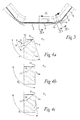
- Fig. 15-18 show the cutting insert 1 according to a variety of the first embodiment of the invention mounted in a milling tool 101 according to the invention.
- the milling tool 101 comprises a tool body 102 and several cutting inserts 1.
- the tool body 102 includes a front end 104 and a rear end 105, between which a central rotation axis C1 extends.
- the tool is rotatable in a direction of rotation R around the central rotation axis C1 and an envelope surface 106 is concentric with the axis C1.
- Several insert seats 107 are formed in a transition between the front end 104 and the envelope surface 106.
- Each insert seat 107 comprises a bottom support surface against which the lower side 3 of the cutting insert 1 rests, a side support comprising two side support surfaces against which two of the recessed support surfaces 14 rest, and a chip pocket 110 provided in front of the insert seat 107 in the direction of rotation R of the tool.
- the cutting inserts 1 are securely and detachably mounted in the insert seats 107 by means of a screw 111.
- the tool shown in fig. 15-19 is configured such that the chip-removing main cutting edge portion 8 is at an entering angle K of around 42°, so that the first secondary cutting edge portion 9 acts as a corner edge, while the second secondary cutting edge portion 10 acts as a surface-wiping secondary edge.
- the entering angle K is the angle that the main cutting edge portion 8 makes with the direction of feed of the milling tool as seen in side elevation view, as shown in fig. 19 .
- the entering angle K is more specifically defined as the angle between a plane P tan and a plane P f measured in a reference plane P ref2 , which planes P tan , P f and P ref2 will be defined below.
- the entering angle varies along the edge, even though the edge is straight.
- the cutting insert 1 is tipped in so that the upper extension plane P U is at a negative radial tipping-in angle ⁇ f of -35°.
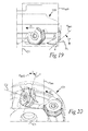
- the radial tipping-in angle ⁇ f shown in fig. 18 , is the angle between the upper extension plane P U and a line along the radial vector r of the tool as seen in planar view. More specifically, the radial tipping-in angle ⁇ f is obtained by taking a plane P f normal to the central rotation axis C1 and passing through a point p k , and in the plane P f measure the angle between a reference plane P ref and the upper extension plane P U as shown in fig. 18 , which is a view in the plane P f .
- the reference plane P ref is a plane spanned by the central rotation axis C1 and a radial vector r perpendicular to the central rotation axis C1 and passing through the point p k .
- the radius r of the tool is measured between the central rotation axis C1 and the point p k , which for this cutting insert 1 is located in the transition between the main cutting edge portion 8 and the adjacent second secondary cutting edge portion 10, in this embodiment a surface-wiping secondary edge.
- ⁇ f With a negative radial tipping-in angle ⁇ f , the upper extension plane P U is directed outwards with regard to the central rotation axis C1 of the tool.
- the cutting insert 1 is further tipped in so that the upper extension plane P U is at a negative axial tipping-in angle ⁇ m of -10°.
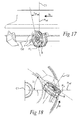
- the axial tipping-in angle ⁇ m shown in fig. 17 , is the angle between the upper extension plane P U and the central rotation axis C1 of the tool. More specifically, the axial tipping-in angle ⁇ m is obtained by measuring the angle between the upper extension plane P U and the reference plane P ref in a plane P m (not shown), which plane P m is perpendicular to the upper extension plane P U , parallel to the central rotation axis C1 and passes through the point p k .
- the upper extension plane P U is inclined towards the front end 104 of the milling tool.
- the main cutting edge portion 8 is at an angle of inclination ⁇ of approximately 20°.
- the angle of inclination ⁇ shown in fig. 20 , is the angle that the main cutting edge portion 8 in a point p a , or a tangent t to the main cutting edge portion 8 in that point, makes with a second reference plane P ref2 .
- the second reference plane P ref2 is parallel with and includes the central rotation axis C1 and includes the point p a on the main cutting edge portion 8.
- the angle of inclination ⁇ is measured in a tangential plane P tan .
- the tangential plane P tan is tangential to the main cutting edge portion 8 in the point p a and is perpendicular to the second reference plane P ref2 .
- the angle of inclination ⁇ is shown by looking at the main cutting edge portion 8 from below the front end 104 of the tool 101, along a line which is normal to the tangential plane P tan .
- the angle of inclination ⁇ is approximately constant along the main cutting edge portion 8, since the main cutting edge portion 8 is essentially rectilinear. For a curved main cutting edge portion, the angle of inclination will vary along the edge.
- the clearance behind the main cutting edge portion 8 in the direction of rotation R of the tool is optimised with regards to the obtuse inner angle ⁇ so that the cutting insert 1 has high strength, while still providing sufficient clearance.
- the clearance behind the surface-wiping secondary cutting edge 10 is sufficient thanks to the negative axial tipping-in angle ⁇ m .
- the clearance behind the main cutting edge portion 8 and the secondary cutting edges 9, 10 is in a suitable range.
- the recessed upper base surface 11 ensures that a positive rake angle is achieved despite the large negative radial tipping-in angle ⁇ f .
- the base surface 11 is in this embodiment formed at a distance of 1.2 mm from the main cutting edge portion 8.
- the chip surface 12 is at the main portion of the main cutting edge 8 inclined at an angle ⁇ 1 between 40° and 55°, here approximately 44°, with respect to the upper extension plane P U .
- the reinforcement land 13 is at an angle ⁇ 2 between 25° and 45°, as shown in fig. 4a .
- the recessed support surfaces 14 formed in the side surface 4 of the cutting insert 1 provide a large support area resting on the side support surfaces of the milling tool 101. This prevents rotation of the cutting insert 1 within the insert seat 107 of the milling tool 101.
- the milling tool in which the cutting insert 1 according to the first embodiment is mounted may instead be configured for an entering angle K of approximately 25°, in which case the first secondary cutting edge portion 9 acts as a surface-wiping secondary edge.
- the second secondary cutting edge portion 10 is for moderate cutting depths not active as a cutting edge.
- the second secondary cutting edge portion 10 adjacent the active main cutting edge portion 8 may be used as a prolongation of the main cutting edge portion 8 if the cutting depth is large.
- the axial tipping-in angle ⁇ m may be set to -17° and the radial tipping-in angle ⁇ f to -45°, in which case the angle of inclination ⁇ is approximately 33°. It is preferable to adjust the radial and the axial tipping-in angles so that the angle of inclination ⁇ is within the range 15° ⁇ ⁇ ⁇ 50°.
- a second embodiment of the cutting insert according to the invention is shown in fig. 5-6 .
- the cutting insert 1 according to this embodiment only differs from the cutting insert of the first embodiment in that it lacks recessed support surfaces. Instead, the side surface 4 extends without recesses from the upper cutting edges 7 to the lower cutting edges 17, including upper clearance surfaces 5, 6a, 6b and lower clearance surfaces 15, 16a, 16b.
- the side surface 4 also includes non-recessed support surfaces 14 extending between the main clearance surfaces 5, 15.
- a third embodiment of the cutting insert according to the invention is shown in fig. 7-9 .
- the cutting insert 1 according to this embodiment is also double-sided and indexable and differs from the cutting insert according to the first embodiment in that it comprises upper cutting edges 7, each including a main cutting edge portion 8 and one secondary cutting edge portion 9 in the form of a surface-wiping secondary edge. Between the secondary cutting edge portion 9 and the subsequent main cutting edge portion 8 is a radial transition. Since the cutting insert 1 is double-sided, the lower side 3 is identical to the upper side 2, with lower cutting edges 17 extending around the lower side 3.
- the cutting insert 1 according to this embodiment further differs from the first embodiment in that it lacks reinforcement land.
- the upper side 2 is formed with a chip surface 12 extending between the upper cutting edges 7 and a recessed upper base surface 11.
- the cutting insert 1 also differs in the design of the side surface 4.
- the side surface 4 comprises upper and lower main clearance surfaces 5, 15 and a secondary clearance surface 6 that extends all the way between the upper secondary cutting edge portion 9 and a corresponding lower secondary cutting edge portion 19.
- the recessed support surfaces 14 are rounded and are only formed below the upper main cutting edge portions 8.
- the upper main clearance surface is formed at an obtuse inner angle ⁇ of 107° with respect to the upper extension plane P U while the secondary clearance surface 6 is formed at a nearly right inner angle ⁇ with respect to the upper extension plane P U .
- the cutting insert is optimised such that at slightly negative axial tipping-in angles and strongly negative radial tipping-in angles, the clearances behind the main cutting edge portion 8 and the secondary cutting edge portion 9 are within a suitable range.
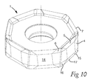
- a fourth embodiment of the cutting insert according to the invention is shown in fig. 10 .
- the cutting insert 1 according to this embodiment only differs from the cutting insert according to the third embodiment in that it lacks recessed support surfaces. Instead, the side surface 4 extends without recesses from the upper cutting edges 7 to the lower cutting edges 17, including upper main clearance surfaces 5, lower main clearance surfaces 15, non-recessed support surfaces 14 extending between the main clearance surfaces 5, 15, and upper and lower secondary clearance surfaces 6, 16.
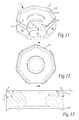
- a fifth embodiment of the cutting insert according to the invention is shown in fig. 11-13 .
- the cutting insert 1 according to this embodiment differs from the third embodiment in that instead of a surface-wiping secondary cutting edge, the secondary cutting edge portion 9 is formed as a curved cutting edge 9 with a corner radius defining the radius of curvature.
- the curved cutting edge portion 9 extends between two adjacent main cutting edge portions 8.
- the cutting insert further differs from the third embodiment in that it comprises a reinforcement land 13 extending between the upper cutting edges 7 and the upper chip surface 12.
- the side surface 4 is formed with rounded recessed support surfaces 14 below the upper main clearance surfaces 5.
- the secondary clearance surface 6 is formed as a curved surface, with a gradual transition between the main clearance surface 5 and the secondary clearance surface 6.
- the cutting insert 1 according to the fifth embodiment is formed with curved cutting edges 9 with a corner radius
- the cutting insert according to this embodiment has mirror symmetry with respect to the line shown in fig. 12 , i.e. a bisector cutting the curved cutting edge 9 in two equal parts.
- the secondary clearance surface 6, below the bisector is formed at a right angle ⁇ with respect to the upper extension plane P U
- the main clearance surface 5 is formed at an obtuse inner angle ⁇ of around 107°.
- the functional clearance behind both the main cutting edge portion 8 and behind the secondary cutting edge portion 9 is approximately 10°.
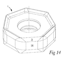
- a sixth embodiment of the cutting insert according to the invention is shown in fig. 14 .
- the cutting insert 1 according to this embodiment differs from the fifth embodiment only in that it lacks recessed support surfaces, but instead has non-recessed support surfaces 14 below the upper main clearance surfaces 5.
- the cutting edges may include curved main cutting edge portions
- the cutting insert may be single-sided with cutting edges extending only around the upper side
- a cutting insert with curved secondary cutting edge portion with a corner radius may be formed with planar recessed side support surfaces instead of rounded
- the insert geometry could be with or without reinforcement land or lands
- the reinforcement land and/or the chip surface may be curved surfaces
- the cutting insert may be formed with a larger number of cutting edges, such as eight cutting edges or more.
- the cutting insert may be designed for left hand rotation of the tool as well as for right hand rotation of the tool.
- the cutting insert may also, instead of being screw mounted, be secured by for example clamps.
Landscapes
- Engineering & Computer Science (AREA)
- Mechanical Engineering (AREA)
- Milling Processes (AREA)
Abstract
Description
- The present invention relates to a cutting insert configured for chip-removing machining of a metallic workpiece by means of milling according to the preamble of
claim 1. The present invention also relates to a milling tool according to the preamble ofclaim 14 comprising a tool body and at least one such cutting insert. - Milling tools for chip-removing machining of metal workpieces are generally composed of a rotatable tool body and a plurality of replaceable cutting inserts made of cemented carbide, ceramics, or other hard material. Since the cutting inserts are subjected to significant wear upon use in a milling tool, it is desirable for the insert to have as many edges as possible in order to prolong the service life of the cutting insert. Cutting inserts are therefore often made double-sided with cutting edges formed along both an upper side and a lower side of the insert, thus doubling the number of cutting edges per insert.
- A face milling tool configured for chip-removing machining and a double-sided cutting insert with seven main cutting edges per side are disclosed in
EP2022584 . The milling tool comprises a tool body including a front end and a rear end, between which a central rotation axis extends around which the tool is rotatable in a direction of rotation and with which an envelope surface is concentric. Several insert seats are formed in a transition between the front end and the envelope surface. Each insert seat comprises a bottom support surface and a side support comprising at least one side support surface. A chip pocket is provided in front of each insert seat in the direction of rotation of the tool. The tool further comprises several cutting inserts securely and detachably mounted in the insert seats. - The cutting insert disclosed in
EP2022584 comprises an upper side defining an upper extension plane and a lower side defining a lower extension plane parallel to the upper extension plane, wherein a centre axis extends perpendicularly through the upper extension plane and the lower extension plane. A side surface connects the upper side and the lower side, the side surface comprising a plurality of main and secondary clearance surfaces. Seven identical and alternately usable upper cutting edges extend around the upper side, wherein each cutting edge comprises a chip removing main cutting edge portion and a secondary cutting edge portion, wherein the main cutting edge portion is formed in a transition between the upper side and one of said main clearance surfaces, and the secondary cutting edge portion is formed in a transition between the upper side and one of said secondary clearance surfaces in a region between two main cutting edge portions. The milling insert has a conventional negative geometry with the clearance surfaces formed at right angles with respect to the upper and lower extension planes of the insert. The cutting insert is mounted in the tool body of the milling tool such that the main cutting edge is at a corner angle of 40°-44° with respect to the axis of rotation of the milling tool. In other words, the entering angle K between the main cutting edge and the direction of feed of the milling tool is 46°-50°. The cutting insert further has curved cutting edges, which serve to ensure a positive effective angle of inclination of the main cutting edge also for negative axial and moderately negative radial tipping-in angles (rake angles). This improves the chip formation properties of the tool for moderate cutting depths. However, the effective angle of inclination is, even with the curved cutting edges, only moderately positive. Drawbacks associated with small effective angles of inclinations, such as cutting characteristics with regards not only to the chip formation and control but also to the toughness behaviour of the cutting edges and the noise level of the tool, are therefore present with a cutting insert and a milling tool disclosed inEP2022584 . - It is an object of the present invention to overcome the problems discussed above and to provide a cutting insert and a milling tool with which it is possible to achieve an improved toughness behaviour of the cutting edges, an improved chip formation and control and a smoother machining resulting in lower noise levels.
- This object is, according to a first aspect of the invention, achieved by the cutting insert initially defined, which is characterised in that each of said upper main clearance surfaces is formed at an obtuse inner angle with respect to the upper extension plane as seen in side elevation view. In other words, the upper main clearance surface is inclined outwards. With this configuration, the angle of inclination of the main cutting edge may be set to strongly positive in a milling tool configured such that the axial tipping-in angle, or axial rake angle, is neutral or negative, the radial tipping-in angle, or radial rake angle, is strongly negative, and the entering angle is acute. With a strongly positive angle of inclination of the main cutting edge, the milling tool operates more smoothly since the main cutting edge portion gradually enters the workpiece, giving lower noise levels and an improved toughness behaviour of the cutting edges. Furthermore, the chip formation is excellent, giving spiral chips which are easily evacuated. Thanks to the possibility of having a large angle of inclination, the cutting insert according to the invention has cutting characteristics similar to a single-sided cutting insert with positive geometry and thereby with a large angle of inclination. Similar to such an insert, it is suitable for milling in stainless steel, such as duplex stainless steel. However, the negative geometry of the cutting insert according to the invention enables more cutting edges per cutting insert and therefore also a better tool economy than with a single-sided positive cutting insert.
- According to one embodiment, the inner angle α between the upper extension plane and each of said upper main clearance surfaces is within the range 93° ≤ α ≤ 118°. An angle smaller than 93° may result in a too large clearance between on one hand the main clearance surface located rotationally behind the chip-removing main cutting edge portion and on the other hand the generally cone-shaped surface generated by the same. A too large clearance reduces the strength of the cutting insert. An angle larger than 118° may instead give an insufficient clearance. According to a preferred embodiment, the inner angle α is within the range 98° ≤ α ≤ 114°, in which range the clearance is optimised.
- According to one embodiment, the upper side comprises a recessed upper base surface extending in parallel with the upper extension plane, and an upper chip surface extending between the upper cutting edges and the upper base surface. With a recessed upper base surface it is possible to achieve a positive rake angle, resulting in improved chip formation, lower cutting forces and thus also reduced power consumption.
- According to one embodiment, the upper side further comprises at least one upper reinforcement land connecting the upper cutting edges with the upper chip surface. The at least one reinforcement land increases the main cutting edge angle, which is the inner angle between the upper main clearance surface and the chip surface as seen in cross section, and thereby increases the strength of the cutting edge. The reinforcement land also acts so as to guide the chip away from the chip surface, reducing friction and thereby also heat generation. This embodiment is particularly advantageous for working at high loads. The width and the angle of the reinforcement land may be varied, but generally a wider reinforcement land enables working at higher loads. It is also possible to have more than one reinforcement lands, for example two reinforcement lands which are arranged in connection to each other and at a slightly different angle with respect to the upper extension plane.
- According to one embodiment, each of said secondary clearance surfaces is formed at an inner angle β with respect to the upper extension plane as seen in side elevation view, wherein β < α. By forming the upper secondary clearance surface, which is located rotationally behind the secondary edge portion, at a smaller angle with respect to the upper extension plane than the upper main clearance surface, it is for negative axial tipping-in angles possible to achieve a clearance which is essentially the same rotationally behind the main cutting edge portion and rotationally behind the secondary cutting edge portion.
- According to one embodiment, the inner angle β between the upper extension plane and the secondary clearance surface below at least a part of the upper secondary cutting edge is within the range 85° ≤ β ≤ 100°. Within this range, the clearance behind the secondary edge portion is optimised for neutral (0°) to slightly negative axial tipping-in angles.
- According to one embodiment, the cutting insert comprises at least seven identical and alternately usable upper cutting edges. The large number of cutting edges prolongs the service life of the cutting insert in comparison with a cutting insert with a smaller number of edges.
- According to one embodiment, the cutting insert is double-sided with the lower side identical to the upper side. This doubles the number of usable cutting edges and thus also doubles the service life in comparison with a single-sided cutting insert. According to one embodiment, the side surface comprises a plurality of recessed support surfaces. By making the support surfaces recessed, their length may be increased so that the total support surface area is increased. The recessed support surfaces, which may be rounded or planar, thereby serve to improve the localisation of the cutting insert in an insert seat of a tool body when the cutting insert forms part of a milling tool, and to prevent rotation of the cutting insert within the insert seat.
- According to one embodiment, the main cutting edge portion is rectilinear or essentially rectilinear. Such a cutting insert generally gives better chip formation along the entire length of the main cutting edge portion than a cutting insert with a curved main cutting edge portion. Thereby, the same cutting insert can, without chip formation problems, be used for different cutting depths.
- According to one embodiment, the secondary cutting edge portion is in the form of a curved edge portion extending between two adjacent main cutting edge portions and having at least one radius of curvature. Such a cutting insert is useful for example for large cutting depths since the main cutting edge portion is relatively long compared to a cutting insert with surface-wiping secondary edges. It also has strong corner regions and may functionally give reduced cutting forces in comparison with cutting inserts with surface-wiping secondary edges. A larger radius of curvature of the curved edge portion gives a stronger corner region. In the case when the cutting insert has curved edge portions, the transitions between the secondary clearance surfaces and the main clearance surfaces is normally gradual, such that there is no sharp edge marking the transition. In this case, it is to be understood that the secondary clearance surface is the surface portion rotationally behind the secondary cutting edge portion, and the main clearance surface is the surface portion rotationally behind the main cutting edge portion.
- According to one embodiment, the secondary cutting edge portion is in the form of at least one facetted edge portion formed between two adjacent main cutting edge portions. Such a facetted edge portion could for example serve as a corner generating edge portion.
- According to one embodiment, the at least one secondary cutting edge portion is in the form of a surface-wiping secondary edge. A cutting insert according to this embodiment may be used to generate planar surfaces and is preferably used for finishing operations. The angle that the surface-wiping secondary edge makes with the main cutting edge portion may be adapted for different entering angles of the milling tool.
- According to one embodiment, each upper cutting edge comprises a first and a second surface-wiping secondary edge formed at an angle with respect to each other as seen in plan view. In this embodiment, it is possible to use the same cutting insert in surface finishing operations with milling tools having different entering angles. It is also possible to form the secondary edges such that when the first secondary edge is used as a surface-wiping secondary edge, the second secondary edge functions as a corner generating edge. This may be advantageous for example when working cast iron in order to reduce the risk of edge frittering.
- According to a second aspect of the invention, the above mentioned object is achieved by the face milling tool initially defined, which is characterised in that the tool comprises at least one cutting insert according to the invention securely and detachably mounted in the at least one insert seat.
- According to an embodiment of this second aspect of the invention, the tool is configured so that a main cutting edge portion is at an entering angle K smaller than 80°, and so that the upper extension plane of the cutting insert is on one hand radially tipped in at a radial tipping-in angle γf within the range - 60° ≤ γf ≤ -25° and on the other hand axially tipped in at an axial tipping-in angle γm within the range -20° ≤ γm ≤ 0°. By means of such a tool, it is possible to achieve a strongly positive inclination angle of the main cutting edge portion, thus achieving the above mentioned advantages.
-
- Fig. 1
- shows a perspective view of a cutting insert according to a first embodiment of the invention;
- Fig. 2
- shows a side view of the cutting insert in
fig. 1 ; - Fig. 3
- shows a partial top view of the cutting insert in
fig. 1 ; - Fig 4a-c
- show partial cross sections along lines IVa, IVb, and IVc in
fig. 3 , respectively, - Fig. 5
- shows a perspective view of a cutting insert according to a second embodiment of the invention;
- Fig. 6
- shows a side view of the cutting insert in
fig. 5 ; - Fig. 7
- shows a perspective view of a cutting insert according to a third embodiment of the invention;
- Fig. 8
- shows a partial top view of the cutting insert in
fig. 7 ; - Fig. 9a-c
- show partial side views and a cross section from the lines IXa-IXa, IXb-IXb and along the line IXc-IXc in
fig. 8 , respectively, - Fig. 10
- shows a perspective view of a cutting insert according to a fourth embodiment of the invention;
- Fig. 11
- shows a perspective view of a cutting insert according to a fifth embodiment of the invention;
- Fig. 12
- shows a top view of the cutting insert in
fig. 11 ; - Fig. 13
- shows a cross section along the line in
fig. 12 ; - Fig. 14
- shows a perspective view of a cutting insert according to a sixth embodiment of the invention;
- Fig. 15
- shows a perspective view of a milling tool according to the invention;
- Fig. 16
- shows a side view of the milling tool in
fig. 15 ; - Fig. 17
- shows the axial tipping-in angle in a partial side view of the milling tool in
fig. 15 ; - Fig. 18
- shows the radial tipping-in angle in a partial planar view of the milling tool in
fig. 15 ; - Fig. 19
- shows the entering angle in a partial side view of the milling tool in
fig. 15 ; and - Fig. 20
- shows the angle of inclination in a partial perspective view of the milling tool in
fig. 15 . - The cutting insert according to a first embodiment of the invention is shown in
fig. 1-4 . The cuttinginsert 1 is double-sided with a polygonal basic shape and comprises anupper side 2 defining an upper extension plane PU and an identicallower side 3 defining a lower extension plane PL, which is parallel to the upper extension plane PU. A centre axis C2 extends perpendicularly through the upper extension plane PU and the lower extension plane PL. Theupper side 2 and thelower side 3 are connected by aside surface 4, which comprises severalmain clearance surfaces secondary clearance surfaces upper side 2, seven identical and alternatelyusable cutting edges 7 extend. Each cutting edge comprises an essentially rectilinear chip removing maincutting edge portion 8 and a first and a second secondarycutting edge portion cutting edge portion 8 is formed in a transition between theupper side 2 and one of the upper main clearance surfaces 5. The first secondarycutting edge portion 9 is formed in a transition between theupper side 2 and a first uppersecondary clearance surface 6a in a region between two maincutting edge portions 8, that is, in a corner region of the cuttinginsert 1. The second secondarycutting edge portion 10 is formed in a transition between theupper side 2 and a second uppersecondary clearance surface 6b. The first secondarycutting edge portion 9 is here configured to act as a surface-wiping secondary edge when the cuttinginsert 1 is mounted in a milling tool with an entering angle K of approximately 25°. If instead the cuttinginsert 1 is mounted in a milling tool with an entering angle K of approximately 42°, the first secondarycutting edge portion 9 acts as a corner edge, while the second secondarycutting edge portion 10 at this entering angle is configured to act as a surface-wiping secondary edge. Thus, themilling insert 1 according to this embodiment can be used for two different entering angles. The edge portions between the maincutting edge portion 8, the first secondarycutting edge portion 9, the second secondarycutting edge portion 10 and the next maincutting edge portion 8 are formed as radial transitions. - The cutting
insert 1 further comprises a recessedupper base surface 11 extending in parallel with the upper extension plane PU. Anupper chip surface 12 extends in the region between theupper cutting edges 7 and theupper base surface 11. Furthermore, between the cuttingedges 7 and thebase surface 11, areinforcement land 13 extends. The cuttinginsert 1 in this first embodiment also comprises, in itsside surface 4, several recessed support surfaces 14 forming a "waist" around the cutting insert. As can be seen infig. 4a and 4b , the radial distance measured from the centre axis C2 to the recessedsupport surface 14 below one of the maincutting edge portions 8 equals the radial distance from the centre axis C2 to the maincutting edge portion 8. However, in the corner region, the corresponding distance between the recessedsupport surface 14 and the centre axis C2 is smaller than the distance from the centre axis C2 to the secondarycutting edge portions support surface 14 and the clearance surfaces 5, 6a, 6b. - As can be seen in
fig. 2 , themain clearance surface 5 is formed at an obtuse inner angle α with respect to the upper extension plane PU as seen in side elevation view. Infig. 4a , a partial cross section taken across the main clearance surface shows the obtuse angle α. In this embodiment, the inner angle α is 107°. Thesecondary clearance surfaces fig. 4b shown in cross section for the upper secondsecondary clearance surface 6b, formed at an angle β2=97°, and infig. 4c shown in cross section for the upper firstsecondary clearance surface 6a, formed at an angle β1=90.5°. - The cutting
insert 1 is indexable to different index positions. In one index position, one of theupper cutting edges 7 is cutting, wherein theupper side 2 partially forms a rake surface and thelower side 3 forms a support surface resting on a bottom support surface of an insert seat of a milling tool. In another index position, one of a number oflower cutting edges 17 extending around thelower side 3 is cutting, wherein thelower side 3 partially forms a rake surface, and theupper side 2 forms a support surface resting on the bottom support surface of the insert seat. -
Fig. 15-18 show the cuttinginsert 1 according to a variety of the first embodiment of the invention mounted in amilling tool 101 according to the invention. Themilling tool 101 comprises atool body 102 and several cutting inserts 1. Thetool body 102 includes afront end 104 and arear end 105, between which a central rotation axis C1 extends. The tool is rotatable in a direction of rotation R around the central rotation axis C1 and anenvelope surface 106 is concentric with the axis C1. Several insert seats 107 are formed in a transition between thefront end 104 and theenvelope surface 106. Eachinsert seat 107 comprises a bottom support surface against which thelower side 3 of the cuttinginsert 1 rests, a side support comprising two side support surfaces against which two of the recessed support surfaces 14 rest, and achip pocket 110 provided in front of theinsert seat 107 in the direction of rotation R of the tool. The cutting inserts 1 are securely and detachably mounted in the insert seats 107 by means of ascrew 111. - The tool shown in
fig. 15-19 is configured such that the chip-removing maincutting edge portion 8 is at an entering angle K of around 42°, so that the first secondarycutting edge portion 9 acts as a corner edge, while the second secondarycutting edge portion 10 acts as a surface-wiping secondary edge. The entering angle K is the angle that the maincutting edge portion 8 makes with the direction of feed of the milling tool as seen in side elevation view, as shown infig. 19 . The entering angle K is more specifically defined as the angle between a plane Ptan and a plane Pf measured in a reference plane Pref2, which planes Ptan, Pf and Pref2 will be defined below. The entering angle varies along the edge, even though the edge is straight. The cuttinginsert 1 is tipped in so that the upper extension plane PU is at a negative radial tipping-in angle γf of -35°. The radial tipping-in angle γf, shown infig. 18 , is the angle between the upper extension plane PU and a line along the radial vector r of the tool as seen in planar view. More specifically, the radial tipping-in angle γf is obtained by taking a plane Pf normal to the central rotation axis C1 and passing through a point pk, and in the plane Pf measure the angle between a reference plane Pref and the upper extension plane PU as shown infig. 18 , which is a view in the plane Pf. The reference plane Pref is a plane spanned by the central rotation axis C1 and a radial vector r perpendicular to the central rotation axis C1 and passing through the point pk. The radius r of the tool is measured between the central rotation axis C1 and the point pk, which for thiscutting insert 1 is located in the transition between the maincutting edge portion 8 and the adjacent second secondarycutting edge portion 10, in this embodiment a surface-wiping secondary edge. With a negative radial tipping-in angle γf, the upper extension plane PU is directed outwards with regard to the central rotation axis C1 of the tool. The cuttinginsert 1 is further tipped in so that the upper extension plane PU is at a negative axial tipping-in angle γm of -10°. The axial tipping-in angle γm, shown infig. 17 , is the angle between the upper extension plane PU and the central rotation axis C1 of the tool. More specifically, the axial tipping-in angle γm is obtained by measuring the angle between the upper extension plane PU and the reference plane Pref in a plane Pm (not shown), which plane Pm is perpendicular to the upper extension plane PU, parallel to the central rotation axis C1 and passes through the point pk. With a negative axial tipping-in angle γm, the upper extension plane PU is inclined towards thefront end 104 of the milling tool. With an entering angle K of approximately 42°, a radial tipping-in angle γf of -35° and an axial tipping-in angle γm of -10°, the maincutting edge portion 8 is at an angle of inclination λ of approximately 20°. The angle of inclination λ, shown infig. 20 , is the angle that the maincutting edge portion 8 in a point pa, or a tangent t to the maincutting edge portion 8 in that point, makes with a second reference plane Pref2. The second reference plane Pref2 is parallel with and includes the central rotation axis C1 and includes the point pa on the maincutting edge portion 8. The angle of inclination λ is measured in a tangential plane Ptan. The tangential plane Ptan is tangential to the maincutting edge portion 8 in the point pa and is perpendicular to the second reference plane Pref2. Infig. 20 , the angle of inclination λ is shown by looking at the maincutting edge portion 8 from below thefront end 104 of thetool 101, along a line which is normal to the tangential plane Ptan. For the cuttinginsert 1 according to the first embodiment, the angle of inclination λ is approximately constant along the maincutting edge portion 8, since the maincutting edge portion 8 is essentially rectilinear. For a curved main cutting edge portion, the angle of inclination will vary along the edge. - With the cutting
insert 1 according to the first embodiment mounted in themilling tool 101 as described above, the clearance behind the maincutting edge portion 8 in the direction of rotation R of the tool is optimised with regards to the obtuse inner angle α so that the cuttinginsert 1 has high strength, while still providing sufficient clearance. The clearance behind the surface-wipingsecondary cutting edge 10 is sufficient thanks to the negative axial tipping-in angle γm. With the chosen values for the inner angles α, β1 and β2, the clearance behind the maincutting edge portion 8 and thesecondary cutting edges upper base surface 11 ensures that a positive rake angle is achieved despite the large negative radial tipping-in angle γf. For this purpose, thebase surface 11 is in this embodiment formed at a distance of 1.2 mm from the maincutting edge portion 8. Thechip surface 12 is at the main portion of themain cutting edge 8 inclined at an angle ϕ1 between 40° and 55°, here approximately 44°, with respect to the upper extension plane PU. Thereinforcement land 13 is at an angle ϕ2 between 25° and 45°, as shown infig. 4a . The recessed support surfaces 14 formed in theside surface 4 of the cuttinginsert 1 provide a large support area resting on the side support surfaces of themilling tool 101. This prevents rotation of the cuttinginsert 1 within theinsert seat 107 of themilling tool 101. - The milling tool in which the
cutting insert 1 according to the first embodiment is mounted may instead be configured for an entering angle K of approximately 25°, in which case the first secondarycutting edge portion 9 acts as a surface-wiping secondary edge. The second secondarycutting edge portion 10 is for moderate cutting depths not active as a cutting edge. However, the second secondarycutting edge portion 10 adjacent the active maincutting edge portion 8 may be used as a prolongation of the maincutting edge portion 8 if the cutting depth is large. For an entering angle K of approximately 25°, the axial tipping-in angle γm may be set to -17° and the radial tipping-in angle γf to -45°, in which case the angle of inclination λ is approximately 33°. It is preferable to adjust the radial and the axial tipping-in angles so that the angle of inclination λ is within therange 15° ≤ λ ≤ 50°. - Further embodiments of the cutting
insert 1 will now be described. It is to be noted that the same reference sign designates the same or a similar element in all embodiments disclosed. - A second embodiment of the cutting insert according to the invention is shown in
fig. 5-6 . The cuttinginsert 1 according to this embodiment only differs from the cutting insert of the first embodiment in that it lacks recessed support surfaces. Instead, theside surface 4 extends without recesses from theupper cutting edges 7 to thelower cutting edges 17, including upper clearance surfaces 5, 6a, 6b and lower clearance surfaces 15, 16a, 16b. Theside surface 4 also includes non-recessed support surfaces 14 extending between themain clearance surfaces - A third embodiment of the cutting insert according to the invention is shown in
fig. 7-9 . The cuttinginsert 1 according to this embodiment is also double-sided and indexable and differs from the cutting insert according to the first embodiment in that it comprisesupper cutting edges 7, each including a maincutting edge portion 8 and one secondarycutting edge portion 9 in the form of a surface-wiping secondary edge. Between the secondarycutting edge portion 9 and the subsequent maincutting edge portion 8 is a radial transition. Since the cuttinginsert 1 is double-sided, thelower side 3 is identical to theupper side 2, withlower cutting edges 17 extending around thelower side 3. The cuttinginsert 1 according to this embodiment further differs from the first embodiment in that it lacks reinforcement land. Instead, theupper side 2 is formed with achip surface 12 extending between theupper cutting edges 7 and a recessedupper base surface 11. The cuttinginsert 1 also differs in the design of theside surface 4. Here, theside surface 4 comprises upper and lowermain clearance surfaces secondary clearance surface 6 that extends all the way between the upper secondarycutting edge portion 9 and a corresponding lower secondarycutting edge portion 19. The recessed support surfaces 14 are rounded and are only formed below the upper maincutting edge portions 8. As can be seen infig. 9a-c , the upper main clearance surface is formed at an obtuse inner angle α of 107° with respect to the upper extension plane PU while thesecondary clearance surface 6 is formed at a nearly right inner angle β with respect to the upper extension plane PU. With these angles, the cutting insert is optimised such that at slightly negative axial tipping-in angles and strongly negative radial tipping-in angles, the clearances behind the maincutting edge portion 8 and the secondarycutting edge portion 9 are within a suitable range. - A fourth embodiment of the cutting insert according to the invention is shown in
fig. 10 . The cuttinginsert 1 according to this embodiment only differs from the cutting insert according to the third embodiment in that it lacks recessed support surfaces. Instead, theside surface 4 extends without recesses from theupper cutting edges 7 to thelower cutting edges 17, including uppermain clearance surfaces 5, lower main clearance surfaces 15, non-recessed support surfaces 14 extending between themain clearance surfaces secondary clearance surfaces - A fifth embodiment of the cutting insert according to the invention is shown in
fig. 11-13 . The cuttinginsert 1 according to this embodiment differs from the third embodiment in that instead of a surface-wiping secondary cutting edge, the secondarycutting edge portion 9 is formed as acurved cutting edge 9 with a corner radius defining the radius of curvature. The curvedcutting edge portion 9 extends between two adjacent maincutting edge portions 8. The cutting insert further differs from the third embodiment in that it comprises areinforcement land 13 extending between theupper cutting edges 7 and theupper chip surface 12. As in the third embodiment, theside surface 4 is formed with rounded recessed support surfaces 14 below the upper main clearance surfaces 5. Thesecondary clearance surface 6 is formed as a curved surface, with a gradual transition between themain clearance surface 5 and thesecondary clearance surface 6. Since the cuttinginsert 1 according to the fifth embodiment is formed withcurved cutting edges 9 with a corner radius, the cutting insert according to this embodiment has mirror symmetry with respect to the line shown infig. 12 , i.e. a bisector cutting thecurved cutting edge 9 in two equal parts. As can be seen infig. 13 , thesecondary clearance surface 6, below the bisector, is formed at a right angle β with respect to the upper extension plane PU, while themain clearance surface 5 is formed at an obtuse inner angle α of around 107°. With a cuttinginsert 1 according to this embodiment mounted in a milling tool with a negative radial tipping-in angle γf of -35° and a negative axial tipping-in angle γm of -10°, the functional clearance behind both the maincutting edge portion 8 and behind the secondarycutting edge portion 9 is approximately 10°. - A sixth embodiment of the cutting insert according to the invention is shown in
fig. 14 . The cuttinginsert 1 according to this embodiment differs from the fifth embodiment only in that it lacks recessed support surfaces, but instead has non-recessed support surfaces 14 below the upper main clearance surfaces 5. - The invention is not limited to the embodiments disclosed but may be varied and modified within the scope of the following claims. For instance, the cutting edges may include curved main cutting edge portions, the cutting insert may be single-sided with cutting edges extending only around the upper side, a cutting insert with curved secondary cutting edge portion with a corner radius may be formed with planar recessed side support surfaces instead of rounded, the insert geometry could be with or without reinforcement land or lands, the reinforcement land and/or the chip surface may be curved surfaces, or the cutting insert may be formed with a larger number of cutting edges, such as eight cutting edges or more. The cutting insert may be designed for left hand rotation of the tool as well as for right hand rotation of the tool. The cutting insert may also, instead of being screw mounted, be secured by for example clamps.
-
- 1
- cutting insert
- 2
- upper side
- 3
- lower side
- 4
- side surface
- 5
- upper main clearance surface
- 6
- secondary clearance surface
- 6a, 6b
- upper secondary clearance surfaces
- 7
- upper cutting edges
- 8
- upper main cutting edge portion
- 9
- upper secondary cutting edge portion
- 10
- upper secondary cutting edge portion
- 11
- base surface
- 12
- chip surface
- 13
- reinforcement land
- 14
- support surfaces
- 15
- lower main clearance surface
- 16
- lower secondary clearance surface
- 16a, 16b
- lower secondary clearance surfaces
- 17
- lower cutting edges
- 19
- lower secondary cutting edge portion
- 101
- milling tool
- 102
- tool body
- 104
- front end
- 105
- rear end
- 106
- envelope surface
- 107
- insert seat
- 110
- chip pocket
- 111
- screw
- PU
- upper extension plane
- PL
- lower extension plane
- Pref
- reference plane
- Pref2
- second reference plane
- Ptan
- tangential plane
- Pf
- plane
- Pm
- plane
- pk
- point
- pa
- point
- C1
- central rotation axis of milling tool
- C2
- centre axis of cutting insert
- r
- radial vector
- t
- tangent
- K
- entering angle
- A
- angle of inclination
- γf
- radial tipping-in angle
- γm
- axial tipping-in angle
- α
- inner angle between PU and main clearance surface
- β, β1, β2
- inner angle between PU and secondary clearance surface
- ϕ1
- angle between PU and chip surface
- ϕ2
- angle between PU and reinforcement land
Claims (15)
- An indexable cutting insert (1) for a milling tool (101), the cutting insert comprising:an upper side (2) defining an upper extension plane (PU);a lower side (3) defining a lower extension plane (PL) parallel to the upper extension plane (PU);wherein a centre axis (C2) extends perpendicularly through the upper extension plane (PU) and the lower extension plane (PL);a side surface (4) connecting the upper side (2) and the lower side (3), the side surface (4) comprising a plurality of upper main clearance surfaces (5) and secondary clearance surfaces (6, 6a, 6b); andat least six identical and alternately usable upper cutting edges (7) extending around the upper side (2), wherein each cutting edge (7) comprises a chip removing main cutting edge portion (8) and at least one secondary cutting edge portion (9, 10), wherein the main cutting edge portion (8) is formed in a transition between the upper side (2) and one of said upper main clearance surfaces (5), and the secondary cutting edge portion (9, 10) is formed in a transition between the upper side (2) and one of said secondary clearance surfaces (6, 6a, 6b) in a region between two main cutting edge portions (8),characterized inthat each of said upper main clearance surfaces (5) is formed at an obtuse inner angle α with respect to the upper extension plane (PU) as seen in side elevation view.
- The cutting insert according to claim 1, wherein the inner angle (α) between the upper extension plane (PU) and each of said upper main clearance surfaces (5) is within the range 93° ≤ α ≤ 118°, preferably within the range 98° ≤ α ≤ 114°.
- The cutting insert according to claim 1 or 2, wherein the upper side (2) comprises a recessed upper base surface (11) extending in parallel with the upper extension plane (PU), and an upper chip surface (12) extending between the upper cutting edges (7) and the upper base surface (11).
- The cutting insert according to claim 3, wherein the upper side (2) further comprises at least one upper reinforcement land (13) connecting the upper cutting edges (7) with the upper chip surface (12).
- The cutting insert according to any of the preceding claims, wherein each of said secondary clearance surfaces (6, 6a, 6b) is formed at an inner angle β with respect to the upper extension plane (PU) as seen in side elevation view, wherein β < α.
- The cutting insert according to claim 5, wherein the inner angle β between the upper extension plane (PU) and the secondary clearance surface (6, 6a, 6b) below at least a part of the upper secondary cutting edge (9, 10) is within the range 85° ≤ β ≤ 100°.
- The cutting insert according to any of the preceding claims, wherein the cutting insert (1) comprises at least seven identical and alternately usable upper cutting edges (7).
- The cutting insert according to any of the preceding claims, wherein the cutting insert (1) is double-sided with the lower side (3) identical to the upper side (2).
- The cutting insert according to any of the preceding claims, wherein the side surface (4) comprises a plurality of recessed support surfaces (14).
- The cutting insert according to any of the preceding claims, wherein the main cutting edge portion (8) is rectilinear or essentially rectilinear.
- The cutting insert according to any of the preceding claims, wherein the secondary cutting edge portion (9) is in the form of a curved edge portion extending between two adjacent main cutting edge portions (8) and having at least one radius of curvature.
- The cutting insert according to any of claims 1-11, wherein the at least one secondary cutting edge portion (9, 10) is in the form of a surface-wiping secondary edge.
- The cutting insert according to claim 12, wherein each upper cutting edge (7) comprises a first and a second surface-wiping secondary edge (9, 10) formed at an angle with respect to each other as seen in plan view.
- A face milling tool (101) configured for chip-removing machining comprising a tool body (102) including a front end (104) and a rear end (105), between which a central rotation axis (C1) extends around which the tool (101) is rotatable in a direction of rotation (R), and at least one insert seat (107) being formed in a transition between the front end (104) and an envelope surface (106) extending between the front end (104) and the rear end (105) of the tool body (102), the at least one insert seat (107) comprising a bottom support surface, wherein a chip pocket (110) is provided in front of the at least one insert seat (107) in the direction of rotation of the tool;
characterized in
that the tool (101) comprises at least one cutting insert (1) according to any of claims 1-13 securely and detachably mounted in the at least one insert seat (107). - The face milling tool (101) according to claim 14, wherein the tool is configured so that a main cutting edge portion (8) is at an entering angle K smaller than 80°, and so that the upper extension plane (PU) of the cutting insert is on one hand radially tipped in at a radial tipping-in angle γf within the range -60° ≤ γf ≤ -25° and on the other hand axially tipped in at an axial tipping-in angle γm within the range -20° ≤ γm ≤ 0°.
Priority Applications (9)
| Application Number | Priority Date | Filing Date | Title |
|---|---|---|---|
| EP14150475.3A EP2893995B1 (en) | 2014-01-08 | 2014-01-08 | A metal cutting insert and a milling tool |
| EP14198988.9A EP2893996B1 (en) | 2014-01-08 | 2014-12-18 | A metal cutting insert and a milling tool |
| RU2014152686A RU2678554C2 (en) | 2014-01-08 | 2014-12-24 | Metal cutting insert and milling tool |
| KR1020150001353A KR102263555B1 (en) | 2014-01-08 | 2015-01-06 | A metal cutting insert and a milling tool |
| US14/591,316 US9975188B2 (en) | 2014-01-08 | 2015-01-07 | Metal cutting insert and a milling tool |
| BR102015000380-3A BR102015000380B1 (en) | 2014-01-08 | 2015-01-08 | metal cutting insert and a milling tool |
| JP2015002539A JP6704223B2 (en) | 2014-01-08 | 2015-01-08 | Metal cutting inserts and milling tools |
| CN201510009671.9A CN104759675B (en) | 2014-01-08 | 2015-01-08 | Metal Cutting Inserts and Milling Tools |
| CN202010503627.4A CN111822766A (en) | 2014-01-08 | 2015-01-08 | Metal cutting insert and milling tool |
Applications Claiming Priority (1)
| Application Number | Priority Date | Filing Date | Title |
|---|---|---|---|
| EP14150475.3A EP2893995B1 (en) | 2014-01-08 | 2014-01-08 | A metal cutting insert and a milling tool |
Publications (2)
| Publication Number | Publication Date |
|---|---|
| EP2893995A1 true EP2893995A1 (en) | 2015-07-15 |
| EP2893995B1 EP2893995B1 (en) | 2019-03-27 |
Family
ID=49916985
Family Applications (2)
| Application Number | Title | Priority Date | Filing Date |
|---|---|---|---|
| EP14150475.3A Active EP2893995B1 (en) | 2014-01-08 | 2014-01-08 | A metal cutting insert and a milling tool |
| EP14198988.9A Active EP2893996B1 (en) | 2014-01-08 | 2014-12-18 | A metal cutting insert and a milling tool |
Family Applications After (1)
| Application Number | Title | Priority Date | Filing Date |
|---|---|---|---|
| EP14198988.9A Active EP2893996B1 (en) | 2014-01-08 | 2014-12-18 | A metal cutting insert and a milling tool |
Country Status (7)
| Country | Link |
|---|---|
| US (1) | US9975188B2 (en) |
| EP (2) | EP2893995B1 (en) |
| JP (1) | JP6704223B2 (en) |
| KR (1) | KR102263555B1 (en) |
| CN (2) | CN104759675B (en) |
| BR (1) | BR102015000380B1 (en) |
| RU (1) | RU2678554C2 (en) |
Cited By (3)
| Publication number | Priority date | Publication date | Assignee | Title |
|---|---|---|---|---|
| EP3338927A1 (en) * | 2016-12-22 | 2018-06-27 | Sandvik Intellectual Property AB | Cutting insert and shoulder milling tool |
| EP3375552A1 (en) | 2017-03-13 | 2018-09-19 | Sandvik Intellectual Property AB | A kit for a milling tool and a milling tool |
| RU2719239C1 (en) * | 2016-05-23 | 2020-04-17 | Хартметалль-Веркцойгфабрик Пауль Хорн Гмбх | Cutting plate for milling tool and milling tool |
Families Citing this family (32)
| Publication number | Priority date | Publication date | Assignee | Title |
|---|---|---|---|---|
| US20160121406A1 (en) | 2014-10-29 | 2016-05-05 | Illinois Tool Works Inc. | Interchangeable cutting inserts and methods associated with the same |
| KR101717279B1 (en) * | 2015-08-28 | 2017-03-16 | 한국야금 주식회사 | Cutting insert and cutting tool for mounting the same |
| AT15155U1 (en) * | 2016-02-26 | 2017-01-15 | Ceratizit Austria Gmbh | peeling plate |
| JP6052455B1 (en) * | 2016-04-19 | 2016-12-27 | 株式会社タンガロイ | Cutting inserts and cutting tools |
| JP6066005B1 (en) * | 2016-04-19 | 2017-01-25 | 株式会社タンガロイ | Cutting inserts and cutting tools |
| USD854063S1 (en) | 2016-08-26 | 2019-07-16 | Sumitomo Electric Hardmetal Corp. | Cutting tool |
| EP3338928B1 (en) * | 2016-12-22 | 2022-03-30 | Sandvik Intellectual Property AB | Cutting insert and shoulder milling tool |
| EP3338926B1 (en) * | 2016-12-22 | 2023-07-26 | Sandvik Intellectual Property AB | Cutting insert and shoulder milling tool |
| EP3351329B1 (en) * | 2017-01-18 | 2023-08-02 | Sandvik Intellectual Property AB | Indexable cutting insert for a milling tool |
| USD815164S1 (en) | 2017-02-09 | 2018-04-10 | Kennametal Inc. | Cutting insert with corner radii cutting surfaces |
| WO2019036159A1 (en) * | 2017-08-18 | 2019-02-21 | Illinois Tool Works Inc. | Interchangeable cutting inserts and methods associated with the same |
| JP1609990S (en) * | 2017-09-21 | 2018-07-30 | ||
| JP1610265S (en) * | 2017-09-21 | 2018-07-30 | ||
| JP1609989S (en) * | 2017-09-21 | 2018-07-30 | ||
| WO2020085245A1 (en) * | 2018-10-23 | 2020-04-30 | 京セラ株式会社 | Cutting insert, cutting tool, and method for manufacturing cut workpiece |
| JP1636989S (en) * | 2018-11-20 | 2019-07-22 | ||
| JP1644939S (en) * | 2019-02-05 | 2019-11-05 | ||
| AT16933U1 (en) * | 2019-07-11 | 2020-12-15 | Ceratizit Austria Gmbh | Double-sided cutting insert for milling |
| US11850670B2 (en) * | 2020-04-24 | 2023-12-26 | Kennametal India Ltd. | Milling cutting inserts |
| JP6855024B1 (en) * | 2020-10-02 | 2021-04-07 | 株式会社タンガロイ | Cutting inserts and cutting tools equipped with them |
| US11583942B2 (en) * | 2020-10-19 | 2023-02-21 | Iscar, Ltd. | Reversible square-shaped cutting insert and rotary cutting tool |
| KR102401104B1 (en) * | 2020-12-28 | 2022-05-23 | 한국야금 주식회사 | Assembly of a cutting insert and a tool holder |
| WO2023063184A1 (en) * | 2021-10-11 | 2023-04-20 | 京セラ株式会社 | Cutting insert, cutting tool, and method for manufacturing cut product |
| JP1716024S (en) * | 2021-10-25 | 2022-05-27 | Inserts for cutting tools | |
| JP1716026S (en) * | 2021-10-25 | 2022-05-27 | Inserts for cutting tools | |
| JP1716025S (en) * | 2021-10-25 | 2022-05-27 | Inserts for cutting tools | |
| USD1029898S1 (en) * | 2022-04-21 | 2024-06-04 | Sumitomo Electric Hardmetal Corp. | Cutting tool insert |
| JP7239043B1 (en) * | 2022-05-26 | 2023-03-14 | 株式会社タンガロイ | cutting insert |
| CN115365555A (en) * | 2022-06-08 | 2022-11-22 | 苏州勤美达精密机械有限公司 | A positive hexagonal corrugated rough and fine milling cutter and its installation structure |
| US11834909B1 (en) | 2023-02-27 | 2023-12-05 | Dynasty Energy Services, LLC | Cutter insert for a section milling tool |
| USD1108509S1 (en) * | 2024-05-10 | 2026-01-06 | Korloy Inc. | Cutting insert for machine tools for metalworking |
| USD1108508S1 (en) * | 2024-05-10 | 2026-01-06 | Korloy Inc. | Cutting insert for machine tools for metalworking |
Citations (6)
| Publication number | Priority date | Publication date | Assignee | Title |
|---|---|---|---|---|
| US20040265073A1 (en) * | 2002-12-24 | 2004-12-30 | Kennametal, Inc. | Toolholder and cutting insert used therein |
| US20050169716A1 (en) * | 2004-02-04 | 2005-08-04 | Iscar, Ltd. | Double-sided cutting insert and milling cutter |
| US20070003384A1 (en) * | 2005-06-30 | 2007-01-04 | Iscar Ltd. | Cutting Insert Having Cylindrically Shaped Side Surface Portions |
| EP2022584A1 (en) | 2006-06-06 | 2009-02-11 | Mitsubishi Materials Corporation | Cutting tool and cutting insert |
| US20110170963A1 (en) * | 2010-01-13 | 2011-07-14 | Iscar, Ltd. | Cutting Insert Having Cutting Edges with Recessed Portions |
| WO2013180160A1 (en) * | 2012-05-30 | 2013-12-05 | 京セラ株式会社 | Cutting insert, cutting tool, and production method for cut object |
Family Cites Families (28)
| Publication number | Priority date | Publication date | Assignee | Title |
|---|---|---|---|---|
| GB940460A (en) | 1960-04-06 | 1963-10-30 | Fagersta Bruks Ab | Improvements relating to metal cutters and metal cutting |
| JPS5821608Y2 (en) * | 1977-07-28 | 1983-05-09 | ダイジヱット工業株式会社 | front milling cutter |
| US5807031A (en) | 1995-03-10 | 1998-09-15 | Mitsubishi Materials Corp. | Throw-away tip and throw-away type cutter |
| JP3180604B2 (en) * | 1995-03-10 | 2001-06-25 | 三菱マテリアル株式会社 | Indexable inserts and indexable cutters |
| CN1154670A (en) * | 1995-03-24 | 1997-07-16 | 伊斯卡有限公司 | Insert blade |
| US5853267A (en) * | 1996-08-22 | 1998-12-29 | Iscar Ltd. | Cutting insert |
| IL129665A (en) * | 1999-04-29 | 2008-06-05 | Rafael Morgulis | Cutting tool assembly and cutting insert therefor |
| DE10361450A1 (en) | 2003-12-23 | 2005-07-28 | EMUGE-Werk Richard Glimpel GmbH & Co. KG Fabrik für Präzisionswerkzeuge | Cutting element and tool with at least one cutting element |
| DE102006011581B4 (en) * | 2006-03-10 | 2016-04-28 | Kennametal Widia Produktions Gmbh & Co. Kg | Cutting insert and milling tool |
| IL182343A0 (en) * | 2007-04-01 | 2007-07-24 | Iscar Ltd | Cutting insert and tool for milling and ramping at high feed rates |
| DE102007022536A1 (en) * | 2007-05-14 | 2008-11-20 | Kennametal Inc. | Eight cutting insert and tool holder for this |
| US7905689B2 (en) * | 2008-05-07 | 2011-03-15 | Tdy Industries, Inc. | Cutting tool system, cutting insert, and tool holder |
| SE533269C2 (en) * | 2008-12-17 | 2010-08-03 | Sandvik Intellectual Property | Double-sided, indexable flat cutter |
| US8491234B2 (en) | 2009-02-12 | 2013-07-23 | TDY Industries, LLC | Double-sided cutting inserts for high feed milling |
| US7976250B2 (en) * | 2009-02-12 | 2011-07-12 | Tdy Industries, Inc. | Double-sided cutting inserts for high feed milling |
| SE0900286A1 (en) * | 2009-03-06 | 2010-07-27 | Seco Tools Ab | Cut with recessed cutting support surface and cutting tools |
| WO2010137663A1 (en) * | 2009-05-28 | 2010-12-02 | 京セラ株式会社 | Cutting insert and cutting tool, and manufacturing method of cut items using same |
| JP2013006221A (en) * | 2009-10-13 | 2013-01-10 | Mitsubishi Materials Corp | Cutting insert and rotating tool with replaceable blade edge |
| JP5620929B2 (en) * | 2010-01-29 | 2014-11-05 | 京セラ株式会社 | Cutting insert, cutting tool, and method of manufacturing a cut product using the same |
| AT12004U1 (en) * | 2010-02-25 | 2011-09-15 | Ceratizit Austria Gmbh | CUTTING INSERT |
| CN103124609B (en) * | 2010-09-27 | 2015-08-19 | 株式会社钨钛合金 | Cutting tip and cutting element |
| EP2492035B1 (en) * | 2011-02-24 | 2016-01-13 | Seco Tools AB | Octagonal cutting insert having edge portion with variable wedge angle, and cutting tool |
| CN106141272B (en) * | 2011-06-30 | 2018-09-14 | 京瓷株式会社 | The manufacturing method of cutting insert and cutting element and machined object |
| DE202011050704U1 (en) * | 2011-07-12 | 2012-10-23 | Jongen Werkzeugtechnik Gmbh & Co. Kg | Insert for mounting in the seat of a milling tool with a polygonal upper surface |
| EP2596889B1 (en) * | 2011-11-23 | 2017-04-26 | Sandvik Intellectual Property AB | A cutting insert and a milling tool |
| US9475134B2 (en) * | 2011-12-19 | 2016-10-25 | Iscar, Ltd. | Cutting insert and cutting tool |
| CN102581365B (en) * | 2012-02-24 | 2014-12-17 | 株洲钻石切削刀具股份有限公司 | Position rotatable blade for milling processing |
| JP5591409B2 (en) | 2012-05-30 | 2014-09-17 | 京セラ株式会社 | Cutting insert, cutting tool and method of manufacturing workpiece |
-
2014
- 2014-01-08 EP EP14150475.3A patent/EP2893995B1/en active Active
- 2014-12-18 EP EP14198988.9A patent/EP2893996B1/en active Active
- 2014-12-24 RU RU2014152686A patent/RU2678554C2/en active
-
2015
- 2015-01-06 KR KR1020150001353A patent/KR102263555B1/en active Active
- 2015-01-07 US US14/591,316 patent/US9975188B2/en active Active
- 2015-01-08 CN CN201510009671.9A patent/CN104759675B/en active Active
- 2015-01-08 CN CN202010503627.4A patent/CN111822766A/en active Pending
- 2015-01-08 BR BR102015000380-3A patent/BR102015000380B1/en active IP Right Grant
- 2015-01-08 JP JP2015002539A patent/JP6704223B2/en active Active
Patent Citations (6)
| Publication number | Priority date | Publication date | Assignee | Title |
|---|---|---|---|---|
| US20040265073A1 (en) * | 2002-12-24 | 2004-12-30 | Kennametal, Inc. | Toolholder and cutting insert used therein |
| US20050169716A1 (en) * | 2004-02-04 | 2005-08-04 | Iscar, Ltd. | Double-sided cutting insert and milling cutter |
| US20070003384A1 (en) * | 2005-06-30 | 2007-01-04 | Iscar Ltd. | Cutting Insert Having Cylindrically Shaped Side Surface Portions |
| EP2022584A1 (en) | 2006-06-06 | 2009-02-11 | Mitsubishi Materials Corporation | Cutting tool and cutting insert |
| US20110170963A1 (en) * | 2010-01-13 | 2011-07-14 | Iscar, Ltd. | Cutting Insert Having Cutting Edges with Recessed Portions |
| WO2013180160A1 (en) * | 2012-05-30 | 2013-12-05 | 京セラ株式会社 | Cutting insert, cutting tool, and production method for cut object |
Cited By (8)
| Publication number | Priority date | Publication date | Assignee | Title |
|---|---|---|---|---|
| RU2719239C1 (en) * | 2016-05-23 | 2020-04-17 | Хартметалль-Веркцойгфабрик Пауль Хорн Гмбх | Cutting plate for milling tool and milling tool |
| US10744576B2 (en) | 2016-05-23 | 2020-08-18 | Hartmetall-Werkzeugfabrik Paul Hom GmbH | Cutting insert for a milling tool and milling tool |
| EP3338927A1 (en) * | 2016-12-22 | 2018-06-27 | Sandvik Intellectual Property AB | Cutting insert and shoulder milling tool |
| WO2018114132A1 (en) * | 2016-12-22 | 2018-06-28 | Sandvik Intellectual Property Ab | Cutting insert and shoulder milling tool |
| US11229960B2 (en) | 2016-12-22 | 2022-01-25 | Sandvik Intellectual Property Ab | Cutting insert and shoulder milling tool |
| EP3375552A1 (en) | 2017-03-13 | 2018-09-19 | Sandvik Intellectual Property AB | A kit for a milling tool and a milling tool |
| WO2018166665A1 (en) | 2017-03-13 | 2018-09-20 | Sandvik Intellectual Property Ab | A kit for a milling tool and a milling tool |
| US11376674B2 (en) | 2017-03-13 | 2022-07-05 | Sandvik Intellectual Property Ab | Kit for a milling tool and a milling tool |
Also Published As
| Publication number | Publication date |
|---|---|
| CN104759675A (en) | 2015-07-08 |
| JP6704223B2 (en) | 2020-06-03 |
| KR102263555B1 (en) | 2021-06-09 |
| CN104759675B (en) | 2021-07-06 |
| EP2893996B1 (en) | 2024-02-28 |
| EP2893996A1 (en) | 2015-07-15 |
| JP2015128816A (en) | 2015-07-16 |
| CN111822766A (en) | 2020-10-27 |
| BR102015000380B1 (en) | 2020-11-24 |
| RU2014152686A3 (en) | 2018-08-01 |
| RU2678554C2 (en) | 2019-01-29 |
| RU2014152686A (en) | 2016-07-10 |
| KR20150083034A (en) | 2015-07-16 |
| US20150190869A1 (en) | 2015-07-09 |
| US9975188B2 (en) | 2018-05-22 |
| EP2893995B1 (en) | 2019-03-27 |
| BR102015000380A2 (en) | 2016-10-25 |
Similar Documents
| Publication | Publication Date | Title |
|---|---|---|
| EP2893995B1 (en) | A metal cutting insert and a milling tool | |
| US10512975B2 (en) | Milling insert and a milling tool | |
| JP5254550B2 (en) | Turning inserts and turning tools | |
| EP2893997B1 (en) | A milling tool | |
| EP2143515B1 (en) | Indexable milling insert | |
| EP3199284B1 (en) | An indexable cutting insert for an end mill tool and an end mill tool provided with such an insert | |
| US10946458B2 (en) | Cutting insert and drilling tool | |
| KR102554780B1 (en) | Square-shaped cutting inserts and rotary cutting tools with curved secondary cutting edges and corner cutting edges | |
| WO2012021206A2 (en) | Contour end mill | |
| CN106687239A (en) | Double-sided cutting insert and milling tool | |
| CN101557899A (en) | Rotary cutting tool | |
| KR20190100195A (en) | Cutting inserts and shoulder milling tools | |
| JP6361948B2 (en) | Cutting inserts and cutting tools | |
| JP2011020192A (en) | Spiral radius end mill | |
| EP2818266A1 (en) | A metal cutting turning insert and a turning tool | |
| EP3593928B1 (en) | A tangential cutting insert and a milling tool | |
| JP2021504157A (en) | Milling inserts capable of single-sided three-way indexing with a high ratio of void volume to material volume and insert mills for that purpose | |
| JP2007098506A (en) | Throw-away tip and throw-away end mill |
Legal Events
| Date | Code | Title | Description |
|---|---|---|---|
| PUAI | Public reference made under article 153(3) epc to a published international application that has entered the european phase |
Free format text: ORIGINAL CODE: 0009012 |
|
| 17P | Request for examination filed |
Effective date: 20140108 |
|
| AK | Designated contracting states |
Kind code of ref document: A1 Designated state(s): AL AT BE BG CH CY CZ DE DK EE ES FI FR GB GR HR HU IE IS IT LI LT LU LV MC MK MT NL NO PL PT RO RS SE SI SK SM TR |
|
| AX | Request for extension of the european patent |
Extension state: BA ME |
|
| R17P | Request for examination filed (corrected) |
Effective date: 20160115 |
|
| RBV | Designated contracting states (corrected) |
Designated state(s): AL AT BE BG CH CY CZ DE DK EE ES FI FR GB GR HR HU IE IS IT LI LT LU LV MC MK MT NL NO PL PT RO RS SE SI SK SM TR |
|
| GRAP | Despatch of communication of intention to grant a patent |
Free format text: ORIGINAL CODE: EPIDOSNIGR1 |
|
| STAA | Information on the status of an ep patent application or granted ep patent |
Free format text: STATUS: GRANT OF PATENT IS INTENDED |
|
| INTG | Intention to grant announced |
Effective date: 20181115 |
|
| GRAS | Grant fee paid |
Free format text: ORIGINAL CODE: EPIDOSNIGR3 |
|
| GRAA | (expected) grant |
Free format text: ORIGINAL CODE: 0009210 |
|
| STAA | Information on the status of an ep patent application or granted ep patent |
Free format text: STATUS: THE PATENT HAS BEEN GRANTED |
|
| AK | Designated contracting states |
Kind code of ref document: B1 Designated state(s): AL AT BE BG CH CY CZ DE DK EE ES FI FR GB GR HR HU IE IS IT LI LT LU LV MC MK MT NL NO PL PT RO RS SE SI SK SM TR |
|
| REG | Reference to a national code |
Ref country code: GB Ref legal event code: FG4D |
|
| REG | Reference to a national code |
Ref country code: CH Ref legal event code: EP |
|
| REG | Reference to a national code |
Ref country code: AT Ref legal event code: REF Ref document number: 1112471 Country of ref document: AT Kind code of ref document: T Effective date: 20190415 |
|
| REG | Reference to a national code |
Ref country code: IE Ref legal event code: FG4D |
|
| REG | Reference to a national code |
Ref country code: DE Ref legal event code: R096 Ref document number: 602014043499 Country of ref document: DE |
|
| PG25 | Lapsed in a contracting state [announced via postgrant information from national office to epo] |
Ref country code: LT Free format text: LAPSE BECAUSE OF FAILURE TO SUBMIT A TRANSLATION OF THE DESCRIPTION OR TO PAY THE FEE WITHIN THE PRESCRIBED TIME-LIMIT Effective date: 20190327 Ref country code: FI Free format text: LAPSE BECAUSE OF FAILURE TO SUBMIT A TRANSLATION OF THE DESCRIPTION OR TO PAY THE FEE WITHIN THE PRESCRIBED TIME-LIMIT Effective date: 20190327 Ref country code: NO Free format text: LAPSE BECAUSE OF FAILURE TO SUBMIT A TRANSLATION OF THE DESCRIPTION OR TO PAY THE FEE WITHIN THE PRESCRIBED TIME-LIMIT Effective date: 20190627 Ref country code: SE Free format text: LAPSE BECAUSE OF FAILURE TO SUBMIT A TRANSLATION OF THE DESCRIPTION OR TO PAY THE FEE WITHIN THE PRESCRIBED TIME-LIMIT Effective date: 20190327 |
|
| REG | Reference to a national code |
Ref country code: NL Ref legal event code: MP Effective date: 20190327 |
|
| PG25 | Lapsed in a contracting state [announced via postgrant information from national office to epo] |
Ref country code: RS Free format text: LAPSE BECAUSE OF FAILURE TO SUBMIT A TRANSLATION OF THE DESCRIPTION OR TO PAY THE FEE WITHIN THE PRESCRIBED TIME-LIMIT Effective date: 20190327 Ref country code: HR Free format text: LAPSE BECAUSE OF FAILURE TO SUBMIT A TRANSLATION OF THE DESCRIPTION OR TO PAY THE FEE WITHIN THE PRESCRIBED TIME-LIMIT Effective date: 20190327 Ref country code: BG Free format text: LAPSE BECAUSE OF FAILURE TO SUBMIT A TRANSLATION OF THE DESCRIPTION OR TO PAY THE FEE WITHIN THE PRESCRIBED TIME-LIMIT Effective date: 20190627 Ref country code: GR Free format text: LAPSE BECAUSE OF FAILURE TO SUBMIT A TRANSLATION OF THE DESCRIPTION OR TO PAY THE FEE WITHIN THE PRESCRIBED TIME-LIMIT Effective date: 20190628 Ref country code: LV Free format text: LAPSE BECAUSE OF FAILURE TO SUBMIT A TRANSLATION OF THE DESCRIPTION OR TO PAY THE FEE WITHIN THE PRESCRIBED TIME-LIMIT Effective date: 20190327 Ref country code: NL Free format text: LAPSE BECAUSE OF FAILURE TO SUBMIT A TRANSLATION OF THE DESCRIPTION OR TO PAY THE FEE WITHIN THE PRESCRIBED TIME-LIMIT Effective date: 20190327 |
|
| REG | Reference to a national code |
Ref country code: AT Ref legal event code: MK05 Ref document number: 1112471 Country of ref document: AT Kind code of ref document: T Effective date: 20190327 |
|
| PG25 | Lapsed in a contracting state [announced via postgrant information from national office to epo] |
Ref country code: EE Free format text: LAPSE BECAUSE OF FAILURE TO SUBMIT A TRANSLATION OF THE DESCRIPTION OR TO PAY THE FEE WITHIN THE PRESCRIBED TIME-LIMIT Effective date: 20190327 Ref country code: SK Free format text: LAPSE BECAUSE OF FAILURE TO SUBMIT A TRANSLATION OF THE DESCRIPTION OR TO PAY THE FEE WITHIN THE PRESCRIBED TIME-LIMIT Effective date: 20190327 Ref country code: RO Free format text: LAPSE BECAUSE OF FAILURE TO SUBMIT A TRANSLATION OF THE DESCRIPTION OR TO PAY THE FEE WITHIN THE PRESCRIBED TIME-LIMIT Effective date: 20190327 Ref country code: ES Free format text: LAPSE BECAUSE OF FAILURE TO SUBMIT A TRANSLATION OF THE DESCRIPTION OR TO PAY THE FEE WITHIN THE PRESCRIBED TIME-LIMIT Effective date: 20190327 Ref country code: PT Free format text: LAPSE BECAUSE OF FAILURE TO SUBMIT A TRANSLATION OF THE DESCRIPTION OR TO PAY THE FEE WITHIN THE PRESCRIBED TIME-LIMIT Effective date: 20190727 Ref country code: CZ Free format text: LAPSE BECAUSE OF FAILURE TO SUBMIT A TRANSLATION OF THE DESCRIPTION OR TO PAY THE FEE WITHIN THE PRESCRIBED TIME-LIMIT Effective date: 20190327 Ref country code: AL Free format text: LAPSE BECAUSE OF FAILURE TO SUBMIT A TRANSLATION OF THE DESCRIPTION OR TO PAY THE FEE WITHIN THE PRESCRIBED TIME-LIMIT Effective date: 20190327 |
|
| PG25 | Lapsed in a contracting state [announced via postgrant information from national office to epo] |
Ref country code: SM Free format text: LAPSE BECAUSE OF FAILURE TO SUBMIT A TRANSLATION OF THE DESCRIPTION OR TO PAY THE FEE WITHIN THE PRESCRIBED TIME-LIMIT Effective date: 20190327 Ref country code: PL Free format text: LAPSE BECAUSE OF FAILURE TO SUBMIT A TRANSLATION OF THE DESCRIPTION OR TO PAY THE FEE WITHIN THE PRESCRIBED TIME-LIMIT Effective date: 20190327 |
|
| REG | Reference to a national code |
Ref country code: DE Ref legal event code: R026 Ref document number: 602014043499 Country of ref document: DE |
|
| PG25 | Lapsed in a contracting state [announced via postgrant information from national office to epo] |
Ref country code: AT Free format text: LAPSE BECAUSE OF FAILURE TO SUBMIT A TRANSLATION OF THE DESCRIPTION OR TO PAY THE FEE WITHIN THE PRESCRIBED TIME-LIMIT Effective date: 20190327 Ref country code: IS Free format text: LAPSE BECAUSE OF FAILURE TO SUBMIT A TRANSLATION OF THE DESCRIPTION OR TO PAY THE FEE WITHIN THE PRESCRIBED TIME-LIMIT Effective date: 20190727 |
|
| PLBI | Opposition filed |
Free format text: ORIGINAL CODE: 0009260 |
|
| PLAX | Notice of opposition and request to file observation + time limit sent |
Free format text: ORIGINAL CODE: EPIDOSNOBS2 |
|
| PG25 | Lapsed in a contracting state [announced via postgrant information from national office to epo] |
Ref country code: DK Free format text: LAPSE BECAUSE OF FAILURE TO SUBMIT A TRANSLATION OF THE DESCRIPTION OR TO PAY THE FEE WITHIN THE PRESCRIBED TIME-LIMIT Effective date: 20190327 |
|
| 26 | Opposition filed |
Opponent name: ISCAR LTD. Effective date: 20191220 |
|
| PG25 | Lapsed in a contracting state [announced via postgrant information from national office to epo] |
Ref country code: SI Free format text: LAPSE BECAUSE OF FAILURE TO SUBMIT A TRANSLATION OF THE DESCRIPTION OR TO PAY THE FEE WITHIN THE PRESCRIBED TIME-LIMIT Effective date: 20190327 |
|
| PG25 | Lapsed in a contracting state [announced via postgrant information from national office to epo] |
Ref country code: TR Free format text: LAPSE BECAUSE OF FAILURE TO SUBMIT A TRANSLATION OF THE DESCRIPTION OR TO PAY THE FEE WITHIN THE PRESCRIBED TIME-LIMIT Effective date: 20190327 |
|
| PLAF | Information modified related to communication of a notice of opposition and request to file observations + time limit |
Free format text: ORIGINAL CODE: EPIDOSCOBS2 |
|
| PLBB | Reply of patent proprietor to notice(s) of opposition received |
Free format text: ORIGINAL CODE: EPIDOSNOBS3 |
|
| PG25 | Lapsed in a contracting state [announced via postgrant information from national office to epo] |
Ref country code: MC Free format text: LAPSE BECAUSE OF FAILURE TO SUBMIT A TRANSLATION OF THE DESCRIPTION OR TO PAY THE FEE WITHIN THE PRESCRIBED TIME-LIMIT Effective date: 20190327 |
|
| REG | Reference to a national code |
Ref country code: CH Ref legal event code: PL |
|
| REG | Reference to a national code |
Ref country code: BE Ref legal event code: MM Effective date: 20200131 |
|
| PG25 | Lapsed in a contracting state [announced via postgrant information from national office to epo] |
Ref country code: LU Free format text: LAPSE BECAUSE OF NON-PAYMENT OF DUE FEES Effective date: 20200108 |
|
| PG25 | Lapsed in a contracting state [announced via postgrant information from national office to epo] |
Ref country code: LI Free format text: LAPSE BECAUSE OF NON-PAYMENT OF DUE FEES Effective date: 20200131 Ref country code: CH Free format text: LAPSE BECAUSE OF NON-PAYMENT OF DUE FEES Effective date: 20200131 Ref country code: BE Free format text: LAPSE BECAUSE OF NON-PAYMENT OF DUE FEES Effective date: 20200131 |
|
| PG25 | Lapsed in a contracting state [announced via postgrant information from national office to epo] |
Ref country code: IE Free format text: LAPSE BECAUSE OF NON-PAYMENT OF DUE FEES Effective date: 20200108 |
|
| REG | Reference to a national code |
Ref country code: CH Ref legal event code: PK Free format text: BERICHTIGUNGEN |
|
| RIC2 | Information provided on ipc code assigned after grant |
Ipc: B23C 5/06 20060101ALI20211007BHEP Ipc: B23C 5/20 20060101AFI20211007BHEP |
|
| APBM | Appeal reference recorded |
Free format text: ORIGINAL CODE: EPIDOSNREFNO |
|
| APBP | Date of receipt of notice of appeal recorded |
Free format text: ORIGINAL CODE: EPIDOSNNOA2O |
|
| APAH | Appeal reference modified |
Free format text: ORIGINAL CODE: EPIDOSCREFNO |
|
| APBQ | Date of receipt of statement of grounds of appeal recorded |
Free format text: ORIGINAL CODE: EPIDOSNNOA3O |
|
| PG25 | Lapsed in a contracting state [announced via postgrant information from national office to epo] |
Ref country code: MT Free format text: LAPSE BECAUSE OF FAILURE TO SUBMIT A TRANSLATION OF THE DESCRIPTION OR TO PAY THE FEE WITHIN THE PRESCRIBED TIME-LIMIT Effective date: 20190327 Ref country code: CY Free format text: LAPSE BECAUSE OF FAILURE TO SUBMIT A TRANSLATION OF THE DESCRIPTION OR TO PAY THE FEE WITHIN THE PRESCRIBED TIME-LIMIT Effective date: 20190327 |
|
| PG25 | Lapsed in a contracting state [announced via postgrant information from national office to epo] |
Ref country code: MK Free format text: LAPSE BECAUSE OF FAILURE TO SUBMIT A TRANSLATION OF THE DESCRIPTION OR TO PAY THE FEE WITHIN THE PRESCRIBED TIME-LIMIT Effective date: 20190327 |
|
| P01 | Opt-out of the competence of the unified patent court (upc) registered |
Effective date: 20230603 |
|
| APBU | Appeal procedure closed |
Free format text: ORIGINAL CODE: EPIDOSNNOA9O |
|
| PLAY | Examination report in opposition despatched + time limit |
Free format text: ORIGINAL CODE: EPIDOSNORE2 |
|
| PGFP | Annual fee paid to national office [announced via postgrant information from national office to epo] |
Ref country code: GB Payment date: 20251204 Year of fee payment: 13 |
|
| PGFP | Annual fee paid to national office [announced via postgrant information from national office to epo] |
Ref country code: FR Payment date: 20251222 Year of fee payment: 13 |
|
| PLAY | Examination report in opposition despatched + time limit |
Free format text: ORIGINAL CODE: EPIDOSNORE2 |
|
| PLBC | Reply to examination report in opposition received |
Free format text: ORIGINAL CODE: EPIDOSNORE3 |
|
| PGFP | Annual fee paid to national office [announced via postgrant information from national office to epo] |
Ref country code: DE Payment date: 20251203 Year of fee payment: 13 |
|
| PGFP | Annual fee paid to national office [announced via postgrant information from national office to epo] |
Ref country code: IT Payment date: 20251219 Year of fee payment: 13 |