WO2012147481A1 - カーテンエアバッグ及びカーテンエアバッグ装置 - Google Patents
カーテンエアバッグ及びカーテンエアバッグ装置 Download PDFInfo
- Publication number
- WO2012147481A1 WO2012147481A1 PCT/JP2012/059306 JP2012059306W WO2012147481A1 WO 2012147481 A1 WO2012147481 A1 WO 2012147481A1 JP 2012059306 W JP2012059306 W JP 2012059306W WO 2012147481 A1 WO2012147481 A1 WO 2012147481A1
- Authority
- WO
- WIPO (PCT)
- Prior art keywords
- curtain airbag
- inflating
- vehicle
- fixing
- inflatable
- Prior art date
- Legal status (The legal status is an assumption and is not a legal conclusion. Google has not performed a legal analysis and makes no representation as to the accuracy of the status listed.)
- Ceased
Links
Images


Classifications
-
- B—PERFORMING OPERATIONS; TRANSPORTING
- B60—VEHICLES IN GENERAL
- B60R—VEHICLES, VEHICLE FITTINGS, OR VEHICLE PARTS, NOT OTHERWISE PROVIDED FOR
- B60R21/00—Arrangements or fittings on vehicles for protecting or preventing injuries to occupants or pedestrians in case of accidents or other traffic risks
- B60R21/02—Occupant safety arrangements or fittings, e.g. crash pads
- B60R21/16—Inflatable occupant restraints or confinements designed to inflate upon impact or impending impact, e.g. air bags
- B60R21/23—Inflatable members
- B60R21/231—Inflatable members characterised by their shape, construction or spatial configuration
- B60R21/232—Curtain-type airbags deploying mainly in a vertical direction from their top edge
-
- B—PERFORMING OPERATIONS; TRANSPORTING
- B60—VEHICLES IN GENERAL
- B60R—VEHICLES, VEHICLE FITTINGS, OR VEHICLE PARTS, NOT OTHERWISE PROVIDED FOR
- B60R21/00—Arrangements or fittings on vehicles for protecting or preventing injuries to occupants or pedestrians in case of accidents or other traffic risks
- B60R21/02—Occupant safety arrangements or fittings, e.g. crash pads
- B60R21/16—Inflatable occupant restraints or confinements designed to inflate upon impact or impending impact, e.g. air bags
- B60R21/20—Arrangements for storing inflatable members in their non-use or deflated condition; Arrangement or mounting of air bag modules or components
- B60R21/213—Arrangements for storing inflatable members in their non-use or deflated condition; Arrangement or mounting of air bag modules or components in vehicle roof frames or pillars
-
- B—PERFORMING OPERATIONS; TRANSPORTING
- B60—VEHICLES IN GENERAL
- B60R—VEHICLES, VEHICLE FITTINGS, OR VEHICLE PARTS, NOT OTHERWISE PROVIDED FOR
- B60R21/00—Arrangements or fittings on vehicles for protecting or preventing injuries to occupants or pedestrians in case of accidents or other traffic risks
- B60R21/02—Occupant safety arrangements or fittings, e.g. crash pads
- B60R21/16—Inflatable occupant restraints or confinements designed to inflate upon impact or impending impact, e.g. air bags
- B60R21/23—Inflatable members
- B60R21/231—Inflatable members characterised by their shape, construction or spatial configuration
- B60R21/2334—Expansion control features
- B60R21/2338—Tethers
-
- B—PERFORMING OPERATIONS; TRANSPORTING
- B60—VEHICLES IN GENERAL
- B60R—VEHICLES, VEHICLE FITTINGS, OR VEHICLE PARTS, NOT OTHERWISE PROVIDED FOR
- B60R21/00—Arrangements or fittings on vehicles for protecting or preventing injuries to occupants or pedestrians in case of accidents or other traffic risks
- B60R21/02—Occupant safety arrangements or fittings, e.g. crash pads
- B60R21/16—Inflatable occupant restraints or confinements designed to inflate upon impact or impending impact, e.g. air bags
- B60R21/23—Inflatable members
- B60R21/231—Inflatable members characterised by their shape, construction or spatial configuration
- B60R21/2334—Expansion control features
- B60R21/2338—Tethers
- B60R2021/23386—External tether means
Definitions
- the present invention relates to a curtain airbag and a curtain airbag device used for a vehicle such as an automobile, and more particularly to a curtain airbag and a curtain airbag device suitable for measures against rollover (rollover) of a vehicle.
- an airbag device for inflating and deploying an airbag in a vehicle to absorb an impact generated by an occupant in an emergency such as a collision or sudden deceleration.
- a curtain airbag device that covers the side window is often mounted in order to suppress the release of passengers during rollover (rollover) of the vehicle.
- Such a curtain airbag device is generally folded in a normal state and stored in the upper part of the vehicle body, and inflated and deployed along a side window in an emergency, an inflator for supplying gas to the curtain airbag, Have In an emergency, gas is supplied from the inflator to the curtain airbag, and the curtain airbag is inflated, released into the vehicle along the side window, and inflated and deployed.
- Patent Document 1 discloses a guide member for guiding an end portion in the front-rear direction of a curtain airbag that is deployed downward along a side surface of a vehicle compartment, and extends in a vertical direction.
- a curtain airbag device having a curtain airbag guide member attached to a pillar is described. According to this configuration, the curtain airbag can be supported by the guide member, and tension can be always applied to the entire curtain airbag.
- Patent Document 2 discloses a substantially triangular non-inflatable having a tip mounting hole at a position below the upper edge mounting portion of the curtain airbag in the deployed state of the airbag alone behind the inflating portion of the curtain airbag.
- a curtain airbag device is described in which a curtain airbag is fixed to a roof side rail by the tip mounting hole and the upper edge mounting portion of the previous period. According to such a configuration, when the curtain airbag is inflated and deployed, the lower end of the substantially triangular rear non-inflatable portion is pulled and the upper portion becomes a hammock shape, which can effectively restrain the head of the occupant.
- JP 200451016 A Japanese Patent Laid-Open No. 2002-220023
- the guide member in the curtain airbag device described in Patent Document 1, the guide member must be arranged in the vertical direction of the vehicle body, and in particular, a single curtain airbag is arranged in the first row of seats (for example, the front seat). In this case, the guide member must be arranged along the B pillar, and it may be difficult to secure the arrangement location. Further, when the guide member is disposed so as to be exposed in the vehicle, the appearance of the vehicle interior is impaired.
- the non-inflatable portion is formed at the rear of the curtain airbag.
- the position where the rear non-inflatable portion is disposed is the last row of seats (for example, It is assumed that the rear seat). Therefore, when a single curtain airbag is arranged in the first row of seats (for example, the front seat), a sufficient space cannot be secured behind the curtain airbag, and a non-inflatable portion is formed. It is difficult to fix to the roof side rail. In this case, if the non-inflatable portion is formed and the non-inflatable portion is fixed to the roof side rail behind the B pillar, the curtain airbag cannot be disposed in the second and subsequent seats, or the inflatable portion is inflated. It will hinder deployment.
- An object of the present invention is to provide a curtain airbag and a curtain airbag device that can suppress the extrusion of the vehicle outside the vehicle.
- a curtain airbag having an inflating portion that is normally folded and stored in the upper part of a vehicle body and inflated and deployed along a side window in an emergency is formed above the inflating portion.
- a third fixing portion disposed at a position below the second fixing portion, and a locking inflating portion formed in a part of the inflating portion so as to cover a part of the B pillar when the inflating and deploying is completed.
- the second fixing part is pulled up and fixed to the upper part of the vehicle body in the vicinity of the B pillar, and the inflating part is inflated and deployed along a side window with respect to the first row seat of the vehicle.
- the curtain airbag is provided, characterized in that.
- a curtain airbag having an inflating portion that is normally folded and stored in the upper part of the vehicle body and is inflated and deployed along a side window in an emergency, and gas is supplied to the inflating portion
- the curtain airbag device includes: a plurality of first fixing portions formed above the inflating portion; and the first fixing portion disposed at an end portion on the rear side of the vehicle.
- a second fixed portion formed at a position below the first portion, a third fixed portion disposed at a front end portion of the vehicle and formed at a position lower than the second fixed portion, and inflated and deployed.
- a locking expansion part formed on a part of the expansion part so as to cover a part of the B pillar, and the second fixing part is pulled up and fixed to the upper part of the vehicle body in the vicinity of the B pillar.
- the inflatable part The vehicle is arranged so as to be inflated and deployed along a side window with respect to the first row of seats of the vehicle, and tension is formed between the third fixing portion and the locking and inflating portion when the inflation and deployment are completed.
- a curtain airbag device is provided.
- the locking and inflating portion is arranged so that the locking and inflating portion is arranged at a horizontal position substantially the same as the arrangement position of the third fixing portion.
- a part may be formed.
- the second fixing portion may be disposed above a vertical center line of the curtain airbag, and the third fixing portion may be disposed below the vertical center line.
- the inflatable portion has a central inflatable portion formed at a central portion of the curtain airbag, and an outer peripheral inflatable portion formed at an outer periphery of the central inflatable portion, and the locking inflatable portion has the outer peripheral inflatable portion. You may be comprised by a part of part.
- the radius of the outer peripheral inflating part constituting the locking inflating part is formed larger than the amount of movement of the central inflating part in the front-rear direction of the vehicle when simulating or evaluating the state in which the occupant is in contact with the curtain airbag May be.
- a second curtain airbag that is inflated and deployed along a side window with respect to the second and subsequent rows of the vehicle is connected to the rear side of the vehicle of the curtain airbag, and the second fixing portion is fixed to the upper portion of the vehicle body. You may make it not.
- the second curtain airbag includes a first inflating portion that inflates and deploys along the C pillar, and a second inflating portion that inflates and deploys substantially horizontally from the first inflating portion along the outer peripheral portion of the side window. And may have.
- the second fixing portion is pulled up and fixed to the upper portion of the vehicle body, so that the inflating portion of the curtain airbag is moved forward by the third fixing portion when inflated and deployed.
- the second fixing is achieved by suppressing the movement or rotation caused by pulling, locking the B pillar and the locking expansion part, and forming a tension between the third fixing part and the locking expansion part. For example, even when a single curtain airbag is arranged in the first row of seats, tension can be applied to the curtain airbag and the curtain airbag can be moved outside the vehicle. Can be suppressed.
- the locking expansion part at a horizontal position substantially the same as the arrangement position of the third fixing part, it is possible to effectively form a tension between the third fixing part and the locking expansion part.
- the second fixed portion is disposed above the center line in the vertical direction of the curtain airbag, and the third fixed portion is disposed below the center line in the vertical direction so that the curtain airbag is disposed on the vehicle rear side. Even if the space for fixing the second fixing portion is limited, the second fixing portion can be fixed to the upper part of the vehicle body, and the second fixing portion and the third fixing portion are arranged at the lowermost end of the curtain airbag. Even if it is not, the tension
- the locking inflating part by forming the locking inflating part by a part of the outer peripheral inflating part, it is possible to smoothly expand and deploy the locking inflating part and to effectively form the locking inflating part.
- the curtain airbag may move in the vehicle forward direction.
- the locked state of the locking inflating portion and the B pillar can be maintained, the tension of the curtain airbag can be maintained, and the curtain airbag can be prevented from being pushed out of the vehicle.
- the curtain airbag can be arranged in the second and subsequent rows of seats. Furthermore, in the second curtain airbag, by forming a first inflatable portion that inflates and deploys along the C pillar, and a second inflatable portion that inflates and deploys substantially horizontally along the outer peripheral portion of the side window, The second curtain airbag can be supported without using a tether or belt that applies tension to the curtain airbag, and the second curtain airbag can be prevented from being pushed out of the vehicle.
- FIG. 6 is a schematic side view of the curtain airbag device showing a state after the curtain airbag shown in FIG. 5 is inflated and deployed.
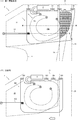
- FIG. 1 is a plan view of the curtain airbag according to the first embodiment of the present invention, in which (A) shows a state before fixing and (B) shows a state after fixing.
- FIG. 2 is a schematic side view of the curtain airbag device showing a state after the inflation and deployment of the curtain airbag shown in FIG. 1 is completed, (A) shows the first embodiment, (B) shows a comparative example.
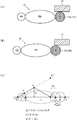
- FIGS. 3A and 3B are explanatory diagrams of the locking inflating portion, in which FIG. 3A shows the first embodiment, FIG. 3B shows a modified example, and FIG. 3C shows a radius calculation method.
- the curtain airbag 1 As shown in FIGS. 1 and 2, the curtain airbag 1 according to the first embodiment of the present invention is normally folded and stored in the vehicle body upper portion 21 of the vehicle 2, and extends along the side window 22 in an emergency.
- a plurality of first fixing portions 11 formed above the inflating portion 10, and disposed at the rear end of the vehicle 2 and below the first fixing portion 11.
- the second fixing portion 12 formed at the position, the third fixing portion 13 disposed at the front end of the vehicle 2 and formed at a position below the second fixing portion 12, and the B pillar when the expansion and deployment is completed
- a second inflating portion 10c formed on a portion of the inflating portion 10 so as to cover a portion of the inflating portion 23.
- the second fixing portion 12 is pulled up and fixed to the vehicle body upper portion 21 in the vicinity of the B pillar 23.
- the inflatable portion 10 is a side with respect to the seat 24 in the first row of the vehicle 2. Are arranged so inflated is deployed along the Indou 22, in which so as to form a tension between the third fixing part 13 and the locking inflatable portion 10c when inflated completely deployed.
- the curtain airbag device includes the curtain airbag 1 described above and the inflator 3 that supplies gas to the inflating portion 10. .
- the vehicle 2 is a commercial vehicle, for example.
- the rear of the first row of seats 24 may be a loading platform, and there is a need to install the curtain airbag 1 only in the portion of the first row of seats 24 that is the front seat.
- the curtain airbag 1 which concerns on this embodiment is not limited to a commercial vehicle, It can apply also to other vehicles, such as a normal vehicle, a van, a truck.
- the vehicle body upper part 21 is a roof side rail formed along the upper part of the side window 22, for example.
- the vehicle body upper portion 21 constitutes a storage place for the curtain airbag 1 in a normal time (a state other than an emergency).
- the inflator 3 has a substantially cylindrical outer shape, and a gas outlet is formed at a tip end included in the curtain airbag 1.
- the inflator 3 is connected to an ECU (electronic control unit) (not shown) and is controlled based on measurement values of an acceleration sensor or the like.
- the ECU electronic control unit
- the inflator 3 is ignited by an ignition current from the ECU, and the chemical stored in the inflator 3 is burned. Gas is generated and supplied to the curtain airbag 1.
- the shape and fixing method of the inflator 3 are not limited to those shown in the drawings, and those conventionally used can be appropriately selected and used.
- the curtain airbag 1 can be divided into a front part 1a having a substantially square shape and a rear part 1b having a substantially triangular shape. And it arrange
- the front portion 1 a has a plurality of first fixing portions 11 arranged at the upper end portion, and this portion forms a fastening point that is fixed to the vehicle body upper portion 21.
- fixed part 12 is arrange
- the rear portion 1b is not limited to a substantially triangular shape, and may have another shape as long as it has a portion located below the upper end portion of the front portion 1a.
- a third fixing portion 13 is disposed at the front end portion of the front portion 1a.
- the third fixing portion 13 is a string-like member such as a tether or a belt for connecting the curtain airbag 1 to the vehicle body, and one end is sewn and connected to the base fabric constituting the curtain airbag 1 and the other end is connected It is fixed to the A pillar of the vehicle 2.
- the second fixing portion 12 is disposed above the vertical center line L of the curtain airbag 1, and the third fixing portion 13 is disposed below the vertical center line L.
- the curtain airbag 1 is generally formed into a bag shape by stitching the base fabric on the front surface and the base fabric on the back surface.
- the inflatable portion 10 is divided into a plurality of regions by stitching lines s1 and s2 that stitch the base fabric on the front surface and the base fabric on the back surface.
- the inflatable portion 10 includes, for example, a central inflatable portion 10a formed at the central portion of the curtain airbag 1 by the suture line s1, and an outer peripheral inflatable portion 10b formed at the outer periphery of the central inflatable portion 10a by the suture line s2. .
- An insertion portion 10g to which a gas outlet of the inflator 3 is connected is formed at the tip of the outer peripheral expansion portion 10b.
- the insertion portion 10g is formed so as to supply gas to the curtain airbag 1 from the vehicle front side toward the vehicle rear side. Note that the position of the insertion portion 10g is not limited to the illustrated location, and is appropriately changed depending on the arrangement position of the inflator 3, and the like. You may make it supply to.
- the gas supplied from the insertion portion 10g inflates the central inflatable portion 10a and rapidly inflates the outer peripheral inflatable portion 10b (particularly, a locking inflatable portion 10c to be described later), so that the curtain airbag 1 is smooth. Can be inflated and deployed.
- the distribution of the gas supply amount of the central expansion portion 10a and the outer peripheral expansion portion 10b can be arbitrarily set depending on the positions of the stitch points s3 and s4.
- the outer peripheral expansion part 10b is formed so as to protrude from the front part 1a to the rear part 1b, and is configured so that the expansion part 10 can be formed also in the rear part 1b.
- the curtain airbag 1 is pulled up to a position at the same height as the first fixing portion 11 and fixed to the vehicle body upper portion 21, and is one of the fastening points. Form.
- the rear portion 1b is pulled upward, the lower end portion of the front portion 1a is also pulled rearward, and the third fixing portion 13 is also pulled rearward.
- the curtain airbag 1 is prevented from moving or rotating forward due to the tension of the third fixing portion 13 when the overall shape contracts due to the inflation of the inflation portion 10. can do.
- the curtain airbag 1 is inflated and deployed so as to cover a part of the side window 22.
- An instrument panel IP is arranged in the vehicle adjacent to the side window 22 and a portion adjacent to the instrument panel IP because it is difficult for an occupant to enter a portion in front of the end of the instrument panel IP. There is little need to inflate and deploy the curtain airbag 1. Therefore, the curtain airbag device can be reduced in size and weight by omitting the curtain airbag 1 in the portion adjacent to the instrument panel IP.
- the curtain airbag 1 is disposed on the upper part 21 of the vehicle body so that a part of the outer peripheral inflating part 10 b overlaps with the B pillar 23. That is, the second fixing portion 12 is pulled up and fixed to the vehicle body upper portion 21 in the vicinity (particularly, the rear side) of the B pillar 23. With this configuration, when the curtain airbag 1 completes inflating and deploying, a part of the outer peripheral inflating portion 10b covers the B pillar 23, and the locking inflating portion 10c (the filled portion in the figure) is configured.
- the inflating portion 10 is formed with a locking inflating portion 10c so that at least a part of the engaging inflating portion 10c is arranged at a horizontal position M substantially the same as the arrangement position of the third fixing portion 13.
- the comparative example shown in FIG. 2B is configured such that the curtain airbag 100 can be inflated and deployed on the side window 22 based on the general idea of a curtain airbag.
- the curtain airbag 100 has a plurality of first fixing portions 101 at the upper end portion and a tether 103 at the front end portion. That is, the curtain airbag 100 is only fixed along the vehicle body upper part 21, and for example, no tension is applied to the lower right portion of the figure. Therefore, when the curtain airbag 100 is inflated and deployed, the amount of contraction is absorbed by the curtain airbag 100 being drawn toward the first fixing portion 101 and the fixing portion of the tether 103.
- the curtain airbag 100 is moved or rotated by being pulled in the direction of the arrow in the figure, and there are fewer locking portions with the vehicle body, and the side window 22 is opened or damaged.
- the curtain airbag 100 is likely to be released to the outside.
- the present invention suppresses movement or rotation of the curtain airbag 1 in the forward direction of the vehicle when the curtain airbag 1 is inflated and deployed, and maintains the locked state between the curtain airbag 1 (locked inflating portion 10c) and the B pillar 23, A tension is formed between the locking and inflating portion 10c and the third fixing portion 13 to suppress release of the curtain airbag 1 to the outside.
- the explanatory view shown in FIG. 3 (A) is a cross-sectional view taken along the line III-III of the curtain airbag 1 in FIG. 2 (A).
- the outer circumferential inflatable portion 10b having a substantially circular cross section is formed on both sides of the central inflatable portion 10a having a substantially elliptic cross section.
- swells and expands to the position which opposes the B pillar 23 comprises the latching expansion part 10c.
- the locking inflating portion 10c is preferably arranged so that the whole can be locked with the B pillar 23, but as shown in FIG. It may be arranged so that more than half of the locking expansion portion 10c can be locked to the B pillar 23.
- the curtain airbag 1 is bent outward.
- the front end point a of the outer peripheral expansion portion 10b and the front end point b of the central expansion portion 10a ( It is assumed that the rear end point of the outer peripheral expansion portion 10b), the front end point c of the locking expansion portion 10c (rear end point of the central expansion portion 10a), and the rear end point d of the locking expansion portion 10c are arranged in a straight line.
- the diameter of the outer peripheral expansion portion 10b is r
- the length of the central expansion portion 10a is L
- the diameter of the locking expansion portion 10c is ⁇ .
- the length of the line segment ac ′′ is r + L
- the length of the line segment ac ′ can be obtained as (r + L) cos ⁇ .
- the radius ( ⁇ / 2) of the locking inflating portion 10c is moved so that the locking inflating portion 10c does not come off from the B pillar 23. It only needs to be larger than the amount ⁇ L. That is, the diameter ⁇ of the locking expansion portion 10c may be set so as to satisfy the relational expression of ⁇ / 2> ⁇ L.
- the diameter ⁇ of the locking inflatable portion 10c can be set using the above relational expression.
- the radius ⁇ / 2 of the outer peripheral inflating portion 10b constituting the locking inflating portion 10c is the longitudinal direction of the vehicle 2 of the central inflating portion 10a when simulating or evaluating the state in which the occupant is in contact with the curtain airbag 1 Is formed to be larger than the movement amount ⁇ L.
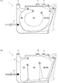
- FIG. 4 is a plan view of a curtain airbag according to another embodiment of the present invention, in which (A) shows a second embodiment and (B) shows a third embodiment.
- the state before the curtain airbag 1 is fixed is indicated by a solid line
- the state after the curtain airbag 1 is indicated by a one-dot chain line.
- symbol is attached
- the curtain airbag 1 according to the second embodiment shown in FIG. 4A is obtained by forming a convex portion 10d on a part of the locking inflatable portion 10c.
- the convex portion 10 d is an inflating portion that protrudes from the locking inflating portion 10 c toward the second fixing portion 12.
- the inflating part By forming the inflating part at a location close to the second fixing part 12, the interval between the second fixing part 12 and the locking inflating part 10 c can be narrowed, and the second fixing part 12 to the vehicle body upper part 21 can be reduced.
- the binding force can be improved. Therefore, the movement or rotation of the curtain airbag 1 in the forward direction of the vehicle when the curtain airbag 1 is inflated and deployed can be further suppressed.
- the curtain airbag 1 according to the third embodiment shown in FIG. 4 (B) is obtained by changing the shape of the inflating portion 10. Specifically, an outer peripheral expansion portion 10b adjacent to the central expansion portion 10a in the vehicle front-rear direction is formed, and the outer peripheral expansion portion 10b on the rear side of the vehicle is used as a locking expansion portion 10c. Even with such a configuration, only the gas supply path is changed, and substantially the same effects as those of the first embodiment can be obtained.
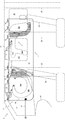
- FIG. 5 is a plan view of the curtain airbag according to the fourth embodiment of the present invention.
- FIG. 6 is a schematic side view of the curtain airbag device showing a state after the inflation and deployment of the curtain airbag shown in FIG. 5 is completed.
- symbol is attached
- the curtain airbag according to the fourth embodiment shown in FIG. 5 and FIG. 6 is a seat in the second row and subsequent rows of the vehicle 2 on the rear side of the vehicle 2 of the curtain airbag 1 according to the first embodiment shown in FIG.
- the second curtain airbag 14 that is inflated and deployed along the side window 26 (for example, the seat 25 in the second row) is connected so that the second fixing portion 12 is not fixed to the vehicle body upper portion 21.
- the second curtain airbag 14 has a length in the vehicle front-rear direction that can cover the second and subsequent rows of seats, and the inflatable portion 15 is formed by the suture lines s5 and s6.
- a plurality of fourth fixing portions 16 are arranged above the inflating portion 15 and are configured so that the second curtain airbag 14 can be fixed to the vehicle body upper portion 21.
- the curtain airbag 1 and the second curtain airbag 14 are connected and integrated by a suture line s7.
- fixed part 12 is inserted between the base fabrics which comprise the front and back of the 2nd curtain airbag 14, and is killed. And it is comprised so that one of the 4th fixing
- a sufficiently long curtain airbag can be formed in the front-rear direction of the vehicle 2, and a curtain can be obtained by using a plurality of pillars. Tension can be formed in the airbag 1 and the second curtain airbag 14, and the extrusion of the curtain airbag 1 and the second curtain airbag 14 to the outside of the vehicle can be suppressed.
- the vehicle 2 has an A pillar 27, a B pillar 23, a C pillar 28, and a D pillar 29 from the front side.
- the roof side rail which comprises the vehicle body upper part 21 is arrange
- the inflating portion 15 of the second curtain airbag 14 includes a first inflating portion 15 a that inflates and deploys along the C pillar 28, and an outer periphery of the side window 26 from the first inflating portion 15 a. And a second inflating portion 15b that is inflated and deployed substantially horizontally along the portion. In addition, a third inflating portion 15 c that is inflated and deployed so as to cover the side window 26 is provided at an adjacent position behind the first inflating portion 15 a and above the second inflating portion 15 b.
- the first expansion portion 15a is locked to the C pillar 28, and the second expansion portion 15b is locked to the outer peripheral portion of the side window 26, thereby supporting the third expansion portion 15c and the third expansion portion 15c. Pushing out of the vehicle can be suppressed.
- the area covering the side window 26 of the third inflating portion 15c is appropriately changed depending on the position of the seat 25 in the second row, the size of the side window 26, and the like.
- the vehicle 2 shown in FIG. 6 is, for example, a commercial vehicle, and has a larger space between the first row of seats 24 and the second row of seats 25 than a normal passenger car, and is loaded with luggage. It is often configured to be able to. Since no occupant is seated between the first row seat 24 and the second row seat 25, there is little need to inflate and deploy the curtain airbag in this portion even if the side window 26 'is formed. .
- the non-inflated portion 17 between the inflated portion 10 of the curtain airbag 1 and the third inflated portion 15c of the second curtain airbag 14 is quickly moved. It is necessary to make it extend. Therefore, the non-inflatable portion 17 between the inflatable portion 10 of the curtain airbag 1 and the third inflatable portion 15c of the second curtain airbag 14 includes the inflatable portion 10 of the curtain airbag 1 and the second curtain airbag 14. You may make it form the 4th expansion part 15d for promoting expansion
- the fourth inflating part 15d may be formed so as to extend both in the front-rear direction and in the up-down direction of the vehicle 2 in order to smoothly expand the non-inflating part 17. If it is necessary to protect passengers or the like also in the side window 26 ', the fourth inflating portion 15d may be formed so as to cover the side window 26', or the first inflating portion 15a to the third inflating portion 15c. You may make it form the expansion part of the structure similar to.
- an insertion portion 15 g to which the gas outlet of the inflator 3 is connected is formed on the upper portion of the expansion portion 15.
- the insertion portion 15g is arranged to supply gas to the second curtain airbag 14 from the vehicle front side toward the rear side.
- the position of the insertion portion 15g is not limited to the illustrated location, and is appropriately changed depending on the arrangement position of the inflator 3, etc., and the gas is supplied from the vehicle rear side toward the vehicle front side. You may make it supply to.
- the curtain airbag 1 can be used even when only the occupants of the first row of seats 24 are desired to be protected. Even if it is desired to protect the passengers in the seat, it can be used by connecting the second curtain airbag 14 and can be switched arbitrarily according to the structure and purpose of use of the vehicle 2 to improve convenience. be able to.
- the present invention is not limited to the above-described embodiments, and the present invention can be applied to a vehicle having three or more rows of seats by forming a plurality of inflatable portions 15 similar to the second curtain airbag 14, etc.
- various modifications can be made without departing from the spirit of the present invention.
Landscapes
- Engineering & Computer Science (AREA)
- Mechanical Engineering (AREA)
- Air Bags (AREA)
Abstract
一列目の座席に単独のカーテンエアバッグを配置する場合であっても、カーテンエアバッグに張力を付与することができ、カーテンエアバッグの車外への押し出しを抑制することができる、カーテンエアバッグ及びカーテンエアバッグ装置を提供する。 膨張部10の上方に形成された複数の第一固定部11と、車両2の後方側に配置され第一固定部11よりも下方の位置に形成された第二固定部12と、車両2の前方側に配置され第二固定部12よりも下方の位置に形成された第三固定部13と、膨張展開完了時にBピラー23の一部を覆うように膨張部10の一部に形成された係止膨張部10cと、を有し、第二固定部12は、Bピラー23の近傍における車体上部21に引上げて固定され、膨張部10は、車両2の一列目の座席24に対するサイドウィンドウ22に沿って膨張展開されるように配置される。
Description
本発明は、自動車等の車両に使用されるカーテンエアバッグ及びカーテンエアバッグ装置に関し、特に、車両のロールオーバー(横転)対策に適したカーテンエアバッグ及びカーテンエアバッグ装置に関する。
自動車等の車両には、衝突時や急減速時等の緊急時に、エアバッグを車内で膨張展開させて乗員に生ずる衝撃を吸収するためのエアバッグ装置が搭載されることが一般的になってきている。特に、車両のロールオーバー(横転)時における乗員の放出を抑制するために、サイドウィンドウを覆うカーテンエアバッグ装置が搭載されることも多い。
かかるカーテンエアバッグ装置は、一般に、通常時は折り畳まれて車体上部に格納されており緊急時にサイドウィンドウに沿って膨張展開されるカーテンエアバッグと、該カーテンエアバッグにガスを供給するインフレータと、を有する。そして、緊急時には、前記インフレータから前記カーテンエアバッグにガスが供給され、前記カーテンエアバッグが膨張し、前記サイドウィンドウに沿って車内に放出され膨張展開する。
ところで、車両のロールオーバー(横転)時にサイドウィンドウが開放されている場合や破損している場合には、乗員がカーテンエアバッグに接触した際に、カーテンエアバッグを支えるものがなく、カーテンエアバッグが車外に押し出されてしまうことがある。そこで、カーテンエアバッグに張力を付与するためのカーテンエアバッグ装置が提案されている(例えば、特許文献1又は特許文献2参照)。
例えば、特許文献1には、車両室内の側面に沿って下方に向って展開するカーテンエアバッグの前後方向の端部を案内するためのガイド部材であって、上下方向に延在し、車両のピラーに取り付けられるカーテンエアバッグのガイド部材を有するカーテンエアバッグ装置が記載されている。かかる構成によれば、ガイド部材によりカーテンエアバッグを支持することができ、常にカーテンエアバッグの全体に張力を付与することができる。
また、特許文献2には、カーテンエアバッグの膨張部後方に、エアバッグ単体での展開状態にてカーテンエアバッグの上縁取付部よりも下方位置に先端取付孔を有する略三角形状の非膨張部を設けて、前記先端取付孔と前期上縁取付部とによりルーフサイドレールにカーテンエアバッグを固定するようにしたカーテンエアバッグ装置が記載されている。かかる構成によれば、カーテンエアバッグの膨張展開時に、略三角形状の後方非膨張部の下端が引っ張られるとともに上部が緩んだハンモック状となり、乗員の頭部を有効に拘束することができる。
しかしながら、特許文献1に記載のカーテンエアバッグ装置では、ガイド部材を車体の上下方向に配置しなければならず、特に、一列目の座席(例えば、前部座席)に単独のカーテンエアバッグを配置する場合には、Bピラーに沿ってガイド部材を配置しなければならず、配置場所の確保が困難な場合がある。また、ガイド部材を車内に露出して配置した場合には、車両内装の見栄えが損なわれてしまう。
また、特許文献2に記載のカーテンエアバッグ装置では、カーテンエアバッグの後方に非膨張部を形成しているが、かかる構成は、後方非膨張部を配置する箇所が最後列の座席(例えば、後部座席)であることを前提としている。したがって、一列目の座席(例えば、前部座席)に単独のカーテンエアバッグを配置する場合には、カーテンエアバッグの後方に十分な空間を確保することができず、非膨張部を形成し、ルーフサイドレールに固定することが困難である。また、この場合に、非膨張部を形成してBピラーよりも後方のルーフサイドレールに非膨張部を固定すると、二列目以降の座席にカーテンエアバッグを配置することができなくなったり、膨張展開を阻害したりしてしまう。
本発明は上述した問題点に鑑み創案されたものであり、一列目の座席に単独のカーテンエアバッグを配置する場合であっても、カーテンエアバッグに張力を付与することができ、カーテンエアバッグの車外への押し出しを抑制することができる、カーテンエアバッグ及びカーテンエアバッグ装置を提供することを目的とする。
本発明によれば、通常時は折り畳まれて車両の車体上部に格納されており緊急時にサイドウィンドウに沿って膨張展開される膨張部を有するカーテンエアバッグであって、前記膨張部の上方に形成された複数の第一固定部と、前記車両の後方側の端部に配置され前記第一固定部よりも下方の位置に形成された第二固定部と、前記車両の前方側の端部に配置され前記第二固定部よりも下方の位置に形成された第三固定部と、膨張展開完了時にBピラーの一部を覆うように前記膨張部の一部に形成された係止膨張部と、を有し、前記第二固定部は、前記Bピラーの近傍における前記車体上部に引上げて固定され、前記膨張部は、前記車両の一列目の座席に対するサイドウィンドウに沿って膨張展開されるように配置され、膨張展開完了時に前記第三固定部と前記係止膨張部との間で張力を形成するようにした、ことを特徴とするカーテンエアバッグが提供される。
また、本発明によれば、通常時は折り畳まれて車両の車体上部に格納されており緊急時にサイドウィンドウに沿って膨張展開される膨張部を有するカーテンエアバッグと、前記膨張部にガスを供給するインフレータと、を有するカーテンエアバッグ装置において、前記カーテンエアバッグは、前記膨張部の上方に形成された複数の第一固定部と、前記車両の後方側の端部に配置され前記第一固定部よりも下方の位置に形成された第二固定部と、前記車両の前方側の端部に配置され前記第二固定部よりも下方の位置に形成された第三固定部と、膨張展開完了時にBピラーの一部を覆うように前記膨張部の一部に形成された係止膨張部と、を有し、前記第二固定部は、前記Bピラーの近傍における前記車体上部に引上げて固定され、前記膨張部は、前記車両の一列目の座席に対するサイドウィンドウに沿って膨張展開されるように配置され、膨張展開完了時に前記第三固定部と前記係止膨張部との間で張力を形成するようにした、ことを特徴とするカーテンエアバッグ装置が提供される。
上述した本発明に係るカーテンエアバッグ及びカーテンエアバッグ装置において、前記膨張部は、前記第三固定部の配置位置と略同じ水平位置に前記係止膨張部が配置されるように前記係止膨張部が形成されていてもよい。
前記第二固定部は、前記カーテンエアバッグの上下方向中心線よりも上方に配置され、前記第三固定部は、前記上下方向中心線よりも下方に配置されていてもよい。
前記膨張部は、前記カーテンエアバッグの中央部に形成された中央膨張部と、該中央膨張部の外周に形成された外周膨張部と、を有し、前記係止膨張部は、前記外周膨張部の一部により構成されていてもよい。
前記係止膨張部を構成する前記外周膨張部の半径は、前記カーテンエアバッグに乗員が接触した状態を模擬又は評価する際における前記中央膨張部の前記車両の前後方向の移動量よりも大きく形成されていてもよい。
前記カーテンエアバッグの前記車両の後方側に前記車両の二列目以降の座席に対するサイドウィンドウに沿って膨張展開される第二カーテンエアバッグが接続され、前記第二固定部を前記車体上部に固定しないようにしてもよい。さらに、前記第二カーテンエアバッグは、Cピラーに沿って膨張展開する第一膨張部と、該第一膨張部から前記サイドウィンドウの外周部に沿って略水平に膨張展開される第二膨張部と、を有していてもよい。
上述した本発明に係るカーテンエアバッグ及びカーテンエアバッグ装置によれば、第二固定部を引上げて車体上部に固定することによって、カーテンエアバッグの膨張部が膨張展開時に第三固定部によって前方に引き寄せられて生ずる移動又は回転を抑制し、Bピラーと係止膨張部とを係止させ、第三固定部と係止膨張部との間で張力を形成するようにしたことにより、第二固定部を固定する空間に制約がある場合、例えば、一列目の座席に単独のカーテンエアバッグを配置する場合であっても、カーテンエアバッグに張力を付与することができ、カーテンエアバッグの車外への押し出しを抑制することができる。
また、第三固定部の配置位置と略同じ水平位置に係止膨張部を配置することにより、第三固定部と係止膨張部との間で効果的に張力を形成することができる。
また、第二固定部がカーテンエアバッグの上下方向中心線よりも上方に配置され、第三固定部が上下方向中心線よりも下方に配置されていることにより、カーテンエアバッグの車両後方側に第二固定部を固定する空間に制約がある場合であっても、第二固定部を車体上部に固定することができ、第二固定部及び第三固定部をカーテンエアバッグの最下端に配置しない場合であっても、第三固定部と係止膨張部との間でカーテンエアバッグの車外への押し出しを抑制することができる張力を形成することができる。
また、係止膨張部を外周膨張部の一部により形成することによって、係止膨張部の膨張展開を円滑に行うことができるとともに、効果的に係止膨張部を形成することができる。
また、係止膨張部の半径を所定の大きさに設定することにより、カーテンエアバッグに乗員が接触した場合又はその状態を模擬若しくは評価する場合にカーテンエアバッグが車両前方方向に移動したとしても係止膨張部とBピラーとの係止状態を維持することができ、カーテンエアバッグの張力を維持することができ、カーテンエアバッグの車外への押し出しを抑制することができる。
また、第二カーテンエアバッグを接続することにより、二列目以降の座席にカーテンエアバッグを配置することができる。さらに、第二カーテンエアバッグに、Cピラーに沿って膨張展開する第一膨張部と、サイドウィンドウの外周部に沿って略水平に膨張展開される第二膨張部と、を形成することにより、カーテンエアバッグに張力を付与するテザーやベルト等を使用することなく、第二カーテンエアバッグを支持することができ、第二カーテンエアバッグの車外への押し出しを抑制することができる。
以下、本発明の実施形態について図1~図6を用いて説明する。ここで、図1は、本発明の第一実施形態に係るカーテンエアバッグの平面図であり、(A)は固定前の状態、(B)は固定後の状態、を示している。図2は、図1に示したカーテンエアバッグの膨張展開完了後の状態を示すカーテンエアバッグ装置の概略側面図であり、(A)は第一実施形態、(B)は比較例、を示している。図3は、係止膨張部の説明図であり、(A)は第一実施形態、(B)は変形例、(C)は半径の算出方法、を示している。
本発明の第一実施形態に係るカーテンエアバッグ1は、図1及び図2に示したように、通常時は折り畳まれて車両2の車体上部21に格納されており緊急時にサイドウィンドウ22に沿って膨張展開される膨張部10を有し、膨張部10の上方に形成された複数の第一固定部11と、車両2の後方側の端部に配置され第一固定部11よりも下方の位置に形成された第二固定部12と、車両2の前方側の端部に配置され第二固定部12よりも下方の位置に形成された第三固定部13と、膨張展開完了時にBピラー23の一部を覆うように膨張部10の一部に形成された係止膨張部10cと、を有し、第二固定部12は、Bピラー23の近傍における車体上部21に引上げて固定され、膨張部10は、車両2の一列目の座席24に対するサイドウィンドウ22に沿って膨張展開されるように配置され、膨張展開完了時に第三固定部13と係止膨張部10cとの間で張力を形成するようにしたものである。
また、図2(A)に示したように、本発明の第一実施形態に係るカーテンエアバッグ装置は、上述したカーテンエアバッグ1と、膨張部10にガスを供給するインフレータ3と、を有する。
車両2は、例えば、商用車である。商用車の場合、一列目の座席24の後方は荷台になっている場合もあり、前部座席である一列目の座席24の部分にのみカーテンエアバッグ1を設置したいというニーズがある。なお、本実施形態に係るカーテンエアバッグ1は、商用車に限定されるものではなく、普通自動車、バン、トラック等の他の車両にも適用することができる。
車体上部21は、例えば、サイドウィンドウ22の上部に沿って形成されるルーフサイドレールである。この車体上部21は、通常時(緊急時以外の状態)におけるカーテンエアバッグ1の格納場所を構成している。
インフレータ3は、略円柱形状の外形をなし、カーテンエアバッグ1に内包された先端部にガス噴出口が形成されている。かかるインフレータ3は、図示しないECU(電子制御ユニット)に接続されており、加速度センサ等の計測値に基づいて制御されている。ECUが車両の衝突、急減速、ロールオーバー(横転)等を感知又は予知したような緊急時には、インフレータ3はECUからの点火電流により点火され、インフレータ3の内部に格納された薬剤を燃焼させてガスを発生させ、カーテンエアバッグ1にガスを供給する。なお、インフレータ3の形状や固定方法は、図示したものに限定されるものではなく、従来から使用されているものを適宜選択して使用することができる。
カーテンエアバッグ1は、図1(A)に示したように、略四角形の形状を有する前方部1aと、略三角形の形状を有する後方部1bと、に区分することができる。そして、後方部1bを構成する一つの頂点が、前方部1aの上端部よりも下方の位置となるように配置されている。前方部1aは、上端部に複数の第一固定部11が配置されており、この部分が車体上部21に固定される留め点を形成する。後方部1bの後端部には第二固定部12が配置されている。なお、後方部1bは、略三角形状に限定されるものではなく、前方部1aの上端部よりも下方に位置する部分を有する形状であれば、他の形状であってもよい。
また、前方部1aの前端部には第三固定部13が配置されている。第三固定部13は、カーテンエアバッグ1を車体に接続するためのテザー又はベルト等の紐状部材であり、一端はカーテンエアバッグ1を構成する基布に縫合されて接続され、他端は車両2のAピラーに固定される。また、例えば、第二固定部12は、カーテンエアバッグ1の上下方向中心線Lよりも上方に配置され、第三固定部13は、上下方向中心線Lよりも下方に配置される。
また、カーテンエアバッグ1は、一般に、表面の基布と裏面の基布とを縫合することにより袋状に形成される。膨張部10は、表面の基布と裏面の基布とを縫合する縫合線s1,s2により、複数の領域に分割される。膨張部10は、例えば、縫合線s1によりカーテンエアバッグ1の中央部に形成された中央膨張部10aと、縫合線s2により中央膨張部10aの外周に形成された外周膨張部10bと、を有する。外周膨張部10bの先端には、インフレータ3のガス噴出口が接続される挿入部10gが形成されている。挿入部10gは、車両前方側から車両後方側に向かってガスをカーテンエアバッグ1に供給するように形成されている。なお、挿入部10gの位置は図示した箇所に限定されるものではなく、インフレータ3の配置位置等によって適宜変更されるものであり、車両後方側から車両前方側に向かってガスをカーテンエアバッグ1に供給するようにしてもよい。
かかる構成により、挿入部10gから供給されたガスは、中央膨張部10aを膨張させるとともに、外周膨張部10b(特に、後述する係止膨張部10c)を速やかに膨張させ、円滑にカーテンエアバッグ1を膨張展開させることができる。中央膨張部10a及び外周膨張部10bのガス供給量の配分は、縫合点s3,s4の位置によって任意に設定することができる。
外周膨張部10bは、前方部1aから後方部1bに渡って張り出すように形成されており、後方部1bにおいても膨張部10を形成することができように構成されている。
カーテンエアバッグ1は、図1(B)に示したように、第二固定部12が第一固定部11と同じ高さの位置まで引上げられて車体上部21に固定され、留め点の一つを形成する。このとき、後方部1bは上方に引上げられることから、前方部1aの下端部も後方に引っ張られ、第三固定部13も後方に引っ張られることとなる。かかる構成により、カーテンエアバッグ1の膨張展開時において、膨張部10の膨張によって全体形状が収縮した場合に、第三固定部13の張力によってカーテンエアバッグ1が前方に移動又は回転しないように抑制することができる。
図2(A)に示したように、カーテンエアバッグ1は、サイドウィンドウ22の一部を覆うように膨張展開する。サイドウィンドウ22と隣接した車内にはインストルメントパネルIPが配置されており、インストルメントパネルIPの端部よりも前方の部分には、乗員が進入し難いことから、インストルメントパネルIPと隣接した部分にはカーテンエアバッグ1を膨張展開させる必要性は少ない。したがって、インストルメントパネルIPと隣接した部分におけるカーテンエアバッグ1を省略することにより、カーテンエアバッグ装置の小型化及び軽量化を図ることができる。
また、外周膨張部10bの一部がBピラー23と重なるように、カーテンエアバッグ1は車体上部21に配置される。すなわち、第二固定部12はBピラー23の近傍(特に、後方側)における車体上部21に引上げて固定される。かかる構成により、カーテンエアバッグ1が膨張展開を完了したときに、外周膨張部10bの一部がBピラー23を覆うこととなり、係止膨張部10c(図の塗り潰した部分)が構成される。
また、膨張部10は、第三固定部13の配置位置と略同じ水平位置Mに、少なくとも係止膨張部10cの一部が配置されるように係止膨張部10cが形成されている。このように、第三固定部13と係止膨張部10cとを略同じ水平位置に形成することにより、第三固定部13と係止膨張部10cとの間で効果的に張力を形成することができる。
ところで、図2(B)に示した比較例は、一般的なカーテンエアバッグの考え方に基づいて、カーテンエアバッグ100をサイドウィンドウ22の部分に膨張展開できるように構成したものである。かかる比較例では、カーテンエアバッグ100の上端部に複数の第一固定部101を有し、前端部にテザー103を有する。すなわち、カーテンエアバッグ100は、車体上部21に沿って固定されているだけであり、例えば、図の右下の部分には張力が付与されていない状態である。したがって、カーテンエアバッグ100が膨張展開した場合には、その収縮量は第一固定部101及びテザー103の固定部にカーテンエアバッグ100が引き寄せられることによって吸収される。その結果、カーテンエアバッグ100は、図の矢印の方向に引き寄せられて移動又は回転し、車体との係止部が少なくなり、サイドウィンドウ22が開放されている場合や破損している場合には、カーテンエアバッグ100が外部に放出され易くなってしまう。
本発明は、カーテンエアバッグ1の膨張展開時における車両前方方向への移動又は回転を抑制するとともに、カーテンエアバッグ1(係止膨張部10c)とBピラー23との係止状態を維持し、係止膨張部10cと第三固定部13との間で張力を形成し、カーテンエアバッグ1の外部への放出を抑制しようとするものである。
ここで、図3(A)に示した説明図は、図2(A)におけるカーテンエアバッグ1のIII-III断面図である。図3(A)に示したように、カーテンエアバッグ1の膨張展開完了時には、略楕円断面形状の中央膨張部10aの両脇に略円断面形状の外周膨張部10bが形成された状態になっている。そして、Bピラー23と対峙する位置に膨張展開する外周膨張部10bが係止膨張部10cを構成している。係止膨張部10cは、図3(A)に示したように、全体がBピラー23と係止可能となるように配置されることが好ましいが、図3(B)に示したように、係止膨張部10cの半分以上の部分がBピラー23と係止可能となるように配置されてもよい。
ところで、膨張展開したカーテンエアバッグ1には乗員が接触することとなる。そのとき、カーテンエアバッグ1には車両左右方向に一定の力が付与されるため、カーテンエアバッグ1は外方に向かって屈曲することとなる。ここで、図3(C)に示したように、乗員が接触する又は乗員が接触した状態を模擬する前の状態において、外周膨張部10bの前端点a、中央膨張部10aの前端点b(外周膨張部10bの後端点)、係止膨張部10cの前端点c(中央膨張部10aの後端点)、係止膨張部10cの後端点dが一直線上に配置されているものとする。また、外周膨張部10bの直径をr、中央膨張部10aの長さをL、係止膨張部10cの直径をφとする。
そして、乗員が接触した場合に、中央膨張部10aの一部(中間点e)が外方に向かって距離Xだけ移動したものとする。このとき、中央膨張部10aの前端点bは点b´に移動し、係止膨張部10cの前端点cは点c´に移動し、係止膨張部10cは破線位置から一点鎖線位置まで移動する。いま、計算の簡略化のために、外周膨張部10bの前端点a、点b´及び中間点eが一直線上に存在するとすれば、その直線上に点c´を投影した点c”を取ることができる。したがって、線分ac”の長さはr+Lとなり、線分ac´の長さは(r+L)cosθと求めることができる。なお、角度θは、中間点eの位置がわかれば、sinθ=X/aeの関係式により容易に求めることができる。
よって、カーテンエアバッグ1が屈曲した場合の移動量ΔLは、ΔL=cc´=(r+L)-(r+L)cosθにより求めることができる。そして、カーテンエアバッグ1がΔLだけ移動した場合であっても、係止膨張部10cがBピラー23から外れないようにするためには、係止膨張部10cの半径(φ/2)が移動量ΔLよりも大きければよい。すなわち、φ/2>ΔLの関係式を満たすように係止膨張部10cの直径φを設定すればよい。特に、設計段階において、カーテンエアバッグ1に乗員が接触した状態を模擬したり、評価したりする場合に、上記関係式を用いて係止膨張部10cの直径φを設定することができる。換言すれば、係止膨張部10cを構成する外周膨張部10bの半径φ/2は、カーテンエアバッグ1に乗員が接触した状態を模擬又は評価する際における中央膨張部10aの車両2の前後方向の移動量ΔLよりも大きく形成される。なお、図3(C)に示した模式図は、係止膨張部10cの半径φ/2の算出方法における単なる一例を示すものであり、カーテンエアバッグ1の形状、負荷のかかる位置、負荷量等の条件によって適宜変更されるものであり、より複雑な計算により係止膨張部10cの半径φ/2を、より正確に算出するようにしてもよい。
次に、本発明の他の実施形態に係るカーテンエアバッグ1について説明する。ここで、図4は、本発明の他の実施形態に係るカーテンエアバッグの平面図であり、(A)は第二実施形態、(B)は第三実施形態、を示している。各図において、カーテンエアバッグ1の固定前の状態を実線で表示し、固定後の状態を一点鎖線で表示している。なお、上述した第一実施形態と同じ構成部品については、同じ符号を付して重複した説明を省略する。
図4(A)に示した第二実施形態に係るカーテンエアバッグ1は、係止膨張部10cの一部に凸部10dを形成したものである。凸部10dは、係止膨張部10cから第二固定部12に向かって突出した膨張部である。第二固定部12に近接した箇所に膨張部を形成することにより、第二固定部12と係止膨張部10cとの間隔を狭くすることができ、第二固定部12の車体上部21への拘束力を向上させることができる。したがって、カーテンエアバッグ1の膨張展開時における車両前方方向への移動又は回転を更に抑制することができる。
図4(B)に示した第三実施形態に係るカーテンエアバッグ1は、膨張部10の形状を変更したものである。具体的には、中央膨張部10aの車両前後方向に隣接した外周膨張部10bを形成し、車両後方側の外周膨張部10bを係止膨張部10cとしたものである。かかる構成であっても、ガスの供給経路が変更になるだけであり、実質的に第一実施形態と同様の効果を奏する。
次に、本発明の第四実施形態に係るカーテンエアバッグについて説明する。ここで、図5は、本発明の第四実施形態に係るカーテンエアバッグの平面図である。図6は、図5に示したカーテンエアバッグの膨張展開完了後の状態を示すカーテンエアバッグ装置の概略側面図である。なお、上述した第一実施形態と同じ構成部品については、同じ符号を付して重複した説明を省略する。
図5及び図6に示した第四実施形態に係るカーテンエアバッグは、図1に示した第一実施形態に係るカーテンエアバッグ1の車両2の後方側に車両2の二列目以降の座席(例えば、二列目の座席25)に対するサイドウィンドウ26に沿って膨張展開される第二カーテンエアバッグ14が接続され、第二固定部12を車体上部21に固定しないようにしたものである。具体的には、第二カーテンエアバッグ14は、二列目以降の座席をカバーし得る車両前後方向の長さを有し、縫合線s5,s6によって膨張部15が形成されている。膨張部15の上方には複数の第四固定部16が配置されており、車体上部21に第二カーテンエアバッグ14を固定できるように構成されている。
また、カーテンエアバッグ1と第二カーテンエアバッグ14とは縫合線s7により接続され一体化されている。このとき、第二固定部12は、第二カーテンエアバッグ14の表裏を構成する基布の間に挿入され、埋め殺される。そして、第二固定部12が固定される予定であった車体上部21には、第四固定部16の一つが固定されるように構成されている。このように、カーテンエアバッグ1に第二カーテンエアバッグ14を接続した場合には、車両2の前後方向に十分長いカーテンエアバッグを形成することができ、複数のピラーを利用することにより、カーテンエアバッグ1及び第二カーテンエアバッグ14に張力を形成することができ、カーテンエアバッグ1及び第二カーテンエアバッグ14の車外への押し出しを抑制することができる。
図6に示したように、車両2は、前方側から、Aピラー27、Bピラー23、Cピラー28、Dピラー29を有する。車体上部21を構成するルーフサイドレールは、これらのピラーに沿って配置される。
第二カーテンエアバッグ14の膨張部15は、図5及び図6に示したように、Cピラー28に沿って膨張展開する第一膨張部15aと、第一膨張部15aからサイドウィンドウ26の外周部に沿って略水平に膨張展開される第二膨張部15bと、を有する。また、第一膨張部15aの後方かつ第二膨張部15bの上方の隣接した箇所には、サイドウィンドウ26を覆うように膨張展開される第三膨張部15cを有する。そして、第一膨張部15aをCピラー28に係止させ、第二膨張部15bをサイドウィンドウ26の外周部に係止させることによって、第三膨張部15cを支持し、第三膨張部15cの車外への押し出しを抑制することができる。第三膨張部15cのサイドウィンドウ26を覆う面積は、二列目の座席25の位置やサイドウィンドウ26の大きさ等によって適宜変更される。
図6に示した車両2は、例えば、商用車であり、一列目の座席24と二列目の座席25との間には、普通乗用車と比較して広い空間を有し、荷物を載せることができるように構成されていることが多い。この一列目の座席24と二列目の座席25との間には乗員が着座しないため、サイドウィンドウ26´が形成されていたとしても、この部分にカーテンエアバッグを膨張展開させる必要性は少ない。
一方で、カーテンエアバッグ1及び第二カーテンエアバッグ14の膨張展開時に、カーテンエアバッグ1の膨張部10と第二カーテンエアバッグ14の第三膨張部15cとの間の非膨張部17を速やかに展張させる必要がある。そこで、カーテンエアバッグ1の膨張部10と第二カーテンエアバッグ14の第三膨張部15cとの間の非膨張部17には、カーテンエアバッグ1の膨張部10及び第二カーテンエアバッグ14の膨張部15の膨張展開を促進するための第四膨張部15dを形成するようにしてもよい。
第四膨張部15dは、非膨張部17を円滑に展張させるために、車両2の前後方向及び上下方向の両方に伸張するように形成するとよい。サイドウィンドウ26´においても乗員等を保護する必要がある場合には、第四膨張部15dがサイドウィンドウ26´を覆うように形成してもよいし、第一膨張部15a~第三膨張部15cと同様の構成の膨張部を形成するようにしてもよい。
なお、膨張部15の上部には、インフレータ3のガス噴出口が接続される挿入部15gが形成されている。挿入部15gは、車両前方側から後方側に向かってガスを第二カーテンエアバッグ14に供給するように配置されている。なお、挿入部15gの位置は図示した箇所に限定されるものではなく、インフレータ3の配置位置等によって適宜変更されるものであり、車両後方側から車両前方側に向かってガスをカーテンエアバッグ1に供給するようにしてもよい。
上述したように本実施形態に係るカーテンエアバッグ1によれば、一列目の座席24の乗員のみを保護したい場合であっても使用することができ、一列目の座席24及び二列目以降の座席の乗員を保護したい場合であっても第二カーテンエアバッグ14を接続することによって使用することができ、車両2の構造や使用目的に応じて任意に切り替えることができ、利便性を向上させることができる。
本発明は上述した実施形態に限定されず、本発明は三列以上の座席を有する車両にも第二カーテンエアバッグ14と同様の膨張部15を複数形成することにより適用することができる等、本発明の趣旨を逸脱しない範囲で種々変更が可能であることは勿論である。
1…カーテンエアバッグ
1a…前方部
1b…後方部
2…車両
3…インフレータ
10…膨張部
10a…中央膨張部
10b…外周膨張部
10c…係止膨張部
10d…凸部
10g…挿入部
11…第一固定部
12…第二固定部
13…第三固定部
14…第二カーテンエアバッグ
15…膨張部
15a…第一膨張部
15b…第二膨張部
15c…第三膨張部
15d…第四膨張部
15g…挿入部
16…第四固定部
21…車体上部
22,26,26´…サイドウィンドウ
23…Bピラー
24…一列目の座席
25…二列目の座席
27…Aピラー
28…Cピラー
29…Dピラー
100…カーテンエアバッグ
101…第一固定部
103…テザー
1a…前方部
1b…後方部
2…車両
3…インフレータ
10…膨張部
10a…中央膨張部
10b…外周膨張部
10c…係止膨張部
10d…凸部
10g…挿入部
11…第一固定部
12…第二固定部
13…第三固定部
14…第二カーテンエアバッグ
15…膨張部
15a…第一膨張部
15b…第二膨張部
15c…第三膨張部
15d…第四膨張部
15g…挿入部
16…第四固定部
21…車体上部
22,26,26´…サイドウィンドウ
23…Bピラー
24…一列目の座席
25…二列目の座席
27…Aピラー
28…Cピラー
29…Dピラー
100…カーテンエアバッグ
101…第一固定部
103…テザー
Claims (8)
- 通常時は折り畳まれて車両の車体上部に格納されており緊急時にサイドウィンドウに沿って膨張展開される膨張部を有するカーテンエアバッグであって、
前記膨張部の上方に形成された複数の第一固定部と、前記車両の後方側の端部に配置され前記第一固定部よりも下方の位置に形成された第二固定部と、前記車両の前方側の端部に配置され前記第二固定部よりも下方の位置に形成された第三固定部と、膨張展開完了時にBピラーの一部を覆うように前記膨張部の一部に形成された係止膨張部と、を有し、
前記第二固定部は、前記Bピラーの近傍における前記車体上部に引上げて固定され、前記膨張部は、前記車両の一列目の座席に対するサイドウィンドウに沿って膨張展開されるように配置され、膨張展開完了時に前記第三固定部と前記係止膨張部との間で張力を形成するようにした、ことを特徴とするカーテンエアバッグ。 - 前記膨張部は、前記第三固定部の配置位置と略同じ水平位置に前記係止膨張部が配置されるように前記係止膨張部が形成されている、ことを特徴とする請求項1に記載のカーテンエアバッグ。
- 前記第二固定部は、前記カーテンエアバッグの上下方向中心線よりも上方に配置され、前記第三固定部は、前記上下方向中心線よりも下方に配置されている、ことを特徴とする請求項1に記載のカーテンエアバッグ。
- 前記膨張部は、前記カーテンエアバッグの中央部に形成された中央膨張部と、該中央膨張部の外周に形成された外周膨張部と、を有し、前記係止膨張部は、前記外周膨張部の一部により構成されている、ことを特徴とする請求項1に記載のカーテンエアバッグ。
- 前記係止膨張部を構成する前記外周膨張部の半径は、前記カーテンエアバッグに乗員が接触した状態を模擬又は評価する際における前記中央膨張部の前記車両の前後方向の移動量よりも大きく形成されている、ことを特徴とする請求項4に記載のカーテンエアバッグ。
- 前記カーテンエアバッグの前記車両の後方側に前記車両の二列目以降の座席に対するサイドウィンドウに沿って膨張展開される第二カーテンエアバッグが接続され、前記第二固定部を前記車体上部に固定しないようにした、ことを特徴とする請求項1に記載のカーテンエアバッグ。
- 前記第二カーテンエアバッグは、Cピラーに沿って膨張展開する第一膨張部と、該第一膨張部から前記サイドウィンドウの外周部に沿って略水平に膨張展開される第二膨張部と、を有することを特徴とする請求項6に記載のカーテンエアバッグ。
- 通常時は折り畳まれて車両の車体上部に格納されており緊急時にサイドウィンドウに沿って膨張展開される膨張部を有するカーテンエアバッグと、前記膨張部にガスを供給するインフレータと、を有するカーテンエアバッグ装置において、前記カーテンエアバッグは、請求項1~請求項7のいずれかに記載のカーテンエアバッグを有する、ことを特徴とするカーテンエアバッグ装置。
Applications Claiming Priority (2)
| Application Number | Priority Date | Filing Date | Title |
|---|---|---|---|
| JP2011100265A JP5788212B2 (ja) | 2011-04-28 | 2011-04-28 | カーテンエアバッグ及びカーテンエアバッグ装置 |
| JP2011-100265 | 2011-04-28 |
Publications (1)
| Publication Number | Publication Date |
|---|---|
| WO2012147481A1 true WO2012147481A1 (ja) | 2012-11-01 |
Family
ID=47072005
Family Applications (1)
| Application Number | Title | Priority Date | Filing Date |
|---|---|---|---|
| PCT/JP2012/059306 Ceased WO2012147481A1 (ja) | 2011-04-28 | 2012-04-05 | カーテンエアバッグ及びカーテンエアバッグ装置 |
Country Status (2)
| Country | Link |
|---|---|
| JP (1) | JP5788212B2 (ja) |
| WO (1) | WO2012147481A1 (ja) |
Families Citing this family (2)
| Publication number | Priority date | Publication date | Assignee | Title |
|---|---|---|---|---|
| JP6696268B2 (ja) * | 2016-03-31 | 2020-05-20 | 豊田合成株式会社 | 頭部保護エアバッグ装置 |
| KR102616206B1 (ko) * | 2016-08-31 | 2023-12-20 | 현대모비스 주식회사 | 차량용 커튼 에어백 장치 |
Citations (4)
| Publication number | Priority date | Publication date | Assignee | Title |
|---|---|---|---|---|
| JP2001171462A (ja) * | 1999-12-14 | 2001-06-26 | Toyoda Gosei Co Ltd | 頭部保護エアバッグ装置のエアバッグ |
| JP2003237521A (ja) * | 2002-02-14 | 2003-08-27 | Ashimori Ind Co Ltd | エアバッグ装置 |
| JP2007022265A (ja) * | 2005-07-14 | 2007-02-01 | Toyoda Gosei Co Ltd | 頭部保護エアバッグ装置 |
| JP2007076517A (ja) * | 2005-09-14 | 2007-03-29 | Toyota Motor Corp | 頭部保護エアバッグ装置 |
-
2011
- 2011-04-28 JP JP2011100265A patent/JP5788212B2/ja not_active Expired - Fee Related
-
2012
- 2012-04-05 WO PCT/JP2012/059306 patent/WO2012147481A1/ja not_active Ceased
Patent Citations (4)
| Publication number | Priority date | Publication date | Assignee | Title |
|---|---|---|---|---|
| JP2001171462A (ja) * | 1999-12-14 | 2001-06-26 | Toyoda Gosei Co Ltd | 頭部保護エアバッグ装置のエアバッグ |
| JP2003237521A (ja) * | 2002-02-14 | 2003-08-27 | Ashimori Ind Co Ltd | エアバッグ装置 |
| JP2007022265A (ja) * | 2005-07-14 | 2007-02-01 | Toyoda Gosei Co Ltd | 頭部保護エアバッグ装置 |
| JP2007076517A (ja) * | 2005-09-14 | 2007-03-29 | Toyota Motor Corp | 頭部保護エアバッグ装置 |
Also Published As
| Publication number | Publication date |
|---|---|
| JP2012232603A (ja) | 2012-11-29 |
| JP5788212B2 (ja) | 2015-09-30 |
Similar Documents
| Publication | Publication Date | Title |
|---|---|---|
| KR101866083B1 (ko) | 자립형 센터 사이드 에어백 | |
| JP5895014B2 (ja) | エアバッグ装置 | |
| JP5641637B2 (ja) | エアバッグ及びエアバッグ装置 | |
| JP5036401B2 (ja) | カーテンサイドエアバッグ装置 | |
| JP4985502B2 (ja) | 後突用エアバッグ装置 | |
| CN114347943A (zh) | 安全气囊装置 | |
| JP2019511414A (ja) | 自動車のファーサイドエアバッグ装置 | |
| JP2012051557A (ja) | エアバッグ装置 | |
| JP2011148431A (ja) | 後突用エアバッグ装置 | |
| US8814201B2 (en) | Knee airbag having increased package width | |
| JP2008296642A (ja) | エアバッグ装置 | |
| JP2008168781A (ja) | カーテンエアバッグの配設構造 | |
| JP5610531B2 (ja) | サイドエアバッグ及びサイドエアバッグ装置 | |
| JP4765561B2 (ja) | 車両乗員拘束装置 | |
| JP5788212B2 (ja) | カーテンエアバッグ及びカーテンエアバッグ装置 | |
| JP2019043197A (ja) | エアバッグ | |
| JP5990156B2 (ja) | カーテンエアバッグ装置 | |
| JP5954273B2 (ja) | 車両用ルーフ付けエアバッグ装置 | |
| JP7494807B2 (ja) | ファーサイドエアバッグ装置 | |
| JP2024106446A (ja) | カーテンエアバッグ装置 | |
| JP6329051B2 (ja) | エアバッグ装置 | |
| JP5034552B2 (ja) | カーテンエアバッグ装置を備えた車両の後部構造 | |
| JP6404542B2 (ja) | カーテンエアバッグ及びカーテンエアバッグ装置 | |
| JP2013095303A (ja) | 乗員拘束装置 | |
| KR101697920B1 (ko) | 사이드 에어백 장치 |
Legal Events
| Date | Code | Title | Description |
|---|---|---|---|
| 121 | Ep: the epo has been informed by wipo that ep was designated in this application |
Ref document number: 12776939 Country of ref document: EP Kind code of ref document: A1 |
|
| NENP | Non-entry into the national phase |
Ref country code: DE |
|
| 122 | Ep: pct application non-entry in european phase |
Ref document number: 12776939 Country of ref document: EP Kind code of ref document: A1 |