WO2012147433A1 - 摩擦部材、クラッチプレート、クラッチ装置、及びトルクコンバータ - Google Patents
摩擦部材、クラッチプレート、クラッチ装置、及びトルクコンバータ Download PDFInfo
- Publication number
- WO2012147433A1 WO2012147433A1 PCT/JP2012/057351 JP2012057351W WO2012147433A1 WO 2012147433 A1 WO2012147433 A1 WO 2012147433A1 JP 2012057351 W JP2012057351 W JP 2012057351W WO 2012147433 A1 WO2012147433 A1 WO 2012147433A1
- Authority
- WO
- WIPO (PCT)
- Prior art keywords
- groove
- clutch plate
- friction member
- input
- friction
- Prior art date
- Legal status (The legal status is an assumption and is not a legal conclusion. Google has not performed a legal analysis and makes no representation as to the accuracy of the status listed.)
- Ceased
Links
Images



Classifications
-
- F—MECHANICAL ENGINEERING; LIGHTING; HEATING; WEAPONS; BLASTING
- F16—ENGINEERING ELEMENTS AND UNITS; GENERAL MEASURES FOR PRODUCING AND MAINTAINING EFFECTIVE FUNCTIONING OF MACHINES OR INSTALLATIONS; THERMAL INSULATION IN GENERAL
- F16D—COUPLINGS FOR TRANSMITTING ROTATION; CLUTCHES; BRAKES
- F16D13/00—Friction clutches
- F16D13/58—Details
- F16D13/60—Clutching elements
- F16D13/64—Clutch-plates; Clutch-lamellae
-
- F—MECHANICAL ENGINEERING; LIGHTING; HEATING; WEAPONS; BLASTING
- F16—ENGINEERING ELEMENTS AND UNITS; GENERAL MEASURES FOR PRODUCING AND MAINTAINING EFFECTIVE FUNCTIONING OF MACHINES OR INSTALLATIONS; THERMAL INSULATION IN GENERAL
- F16D—COUPLINGS FOR TRANSMITTING ROTATION; CLUTCHES; BRAKES
- F16D13/00—Friction clutches
- F16D13/58—Details
- F16D13/60—Clutching elements
- F16D13/62—Clutch-bands; Clutch shoes; Clutch-drums
-
- F—MECHANICAL ENGINEERING; LIGHTING; HEATING; WEAPONS; BLASTING
- F16—ENGINEERING ELEMENTS AND UNITS; GENERAL MEASURES FOR PRODUCING AND MAINTAINING EFFECTIVE FUNCTIONING OF MACHINES OR INSTALLATIONS; THERMAL INSULATION IN GENERAL
- F16D—COUPLINGS FOR TRANSMITTING ROTATION; CLUTCHES; BRAKES
- F16D13/00—Friction clutches
- F16D13/58—Details
- F16D13/60—Clutching elements
- F16D13/64—Clutch-plates; Clutch-lamellae
- F16D13/648—Clutch-plates; Clutch-lamellae for clutches with multiple lamellae
-
- F—MECHANICAL ENGINEERING; LIGHTING; HEATING; WEAPONS; BLASTING
- F16—ENGINEERING ELEMENTS AND UNITS; GENERAL MEASURES FOR PRODUCING AND MAINTAINING EFFECTIVE FUNCTIONING OF MACHINES OR INSTALLATIONS; THERMAL INSULATION IN GENERAL
- F16D—COUPLINGS FOR TRANSMITTING ROTATION; CLUTCHES; BRAKES
- F16D25/00—Fluid-actuated clutches
- F16D25/06—Fluid-actuated clutches in which the fluid actuates a piston incorporated in, i.e. rotating with the clutch
- F16D25/062—Fluid-actuated clutches in which the fluid actuates a piston incorporated in, i.e. rotating with the clutch the clutch having friction surfaces
- F16D25/063—Fluid-actuated clutches in which the fluid actuates a piston incorporated in, i.e. rotating with the clutch the clutch having friction surfaces with clutch members exclusively moving axially
- F16D25/0635—Fluid-actuated clutches in which the fluid actuates a piston incorporated in, i.e. rotating with the clutch the clutch having friction surfaces with clutch members exclusively moving axially with flat friction surfaces, e.g. discs
- F16D25/0638—Fluid-actuated clutches in which the fluid actuates a piston incorporated in, i.e. rotating with the clutch the clutch having friction surfaces with clutch members exclusively moving axially with flat friction surfaces, e.g. discs with more than two discs, e.g. multiple lamellae
-
- F—MECHANICAL ENGINEERING; LIGHTING; HEATING; WEAPONS; BLASTING
- F16—ENGINEERING ELEMENTS AND UNITS; GENERAL MEASURES FOR PRODUCING AND MAINTAINING EFFECTIVE FUNCTIONING OF MACHINES OR INSTALLATIONS; THERMAL INSULATION IN GENERAL
- F16H—GEARING
- F16H41/00—Rotary fluid gearing of the hydrokinetic type
- F16H41/24—Details
-
- F—MECHANICAL ENGINEERING; LIGHTING; HEATING; WEAPONS; BLASTING
- F16—ENGINEERING ELEMENTS AND UNITS; GENERAL MEASURES FOR PRODUCING AND MAINTAINING EFFECTIVE FUNCTIONING OF MACHINES OR INSTALLATIONS; THERMAL INSULATION IN GENERAL
- F16H—GEARING
- F16H45/00—Combinations of fluid gearings for conveying rotary motion with couplings or clutches
- F16H45/02—Combinations of fluid gearings for conveying rotary motion with couplings or clutches with mechanical clutches for bridging a fluid gearing of the hydrokinetic type
-
- F—MECHANICAL ENGINEERING; LIGHTING; HEATING; WEAPONS; BLASTING
- F16—ENGINEERING ELEMENTS AND UNITS; GENERAL MEASURES FOR PRODUCING AND MAINTAINING EFFECTIVE FUNCTIONING OF MACHINES OR INSTALLATIONS; THERMAL INSULATION IN GENERAL
- F16D—COUPLINGS FOR TRANSMITTING ROTATION; CLUTCHES; BRAKES
- F16D69/00—Friction linings; Attachment thereof; Selection of coacting friction substances or surfaces
- F16D2069/004—Profiled friction surfaces, e.g. grooves, dimples
-
- F—MECHANICAL ENGINEERING; LIGHTING; HEATING; WEAPONS; BLASTING
- F16—ENGINEERING ELEMENTS AND UNITS; GENERAL MEASURES FOR PRODUCING AND MAINTAINING EFFECTIVE FUNCTIONING OF MACHINES OR INSTALLATIONS; THERMAL INSULATION IN GENERAL
- F16H—GEARING
- F16H45/00—Combinations of fluid gearings for conveying rotary motion with couplings or clutches
- F16H45/02—Combinations of fluid gearings for conveying rotary motion with couplings or clutches with mechanical clutches for bridging a fluid gearing of the hydrokinetic type
- F16H2045/0205—Combinations of fluid gearings for conveying rotary motion with couplings or clutches with mechanical clutches for bridging a fluid gearing of the hydrokinetic type two chamber system, i.e. without a separated, closed chamber specially adapted for actuating a lock-up clutch
-
- F—MECHANICAL ENGINEERING; LIGHTING; HEATING; WEAPONS; BLASTING
- F16—ENGINEERING ELEMENTS AND UNITS; GENERAL MEASURES FOR PRODUCING AND MAINTAINING EFFECTIVE FUNCTIONING OF MACHINES OR INSTALLATIONS; THERMAL INSULATION IN GENERAL
- F16H—GEARING
- F16H45/00—Combinations of fluid gearings for conveying rotary motion with couplings or clutches
- F16H45/02—Combinations of fluid gearings for conveying rotary motion with couplings or clutches with mechanical clutches for bridging a fluid gearing of the hydrokinetic type
- F16H2045/0221—Combinations of fluid gearings for conveying rotary motion with couplings or clutches with mechanical clutches for bridging a fluid gearing of the hydrokinetic type with damping means
-
- F—MECHANICAL ENGINEERING; LIGHTING; HEATING; WEAPONS; BLASTING
- F16—ENGINEERING ELEMENTS AND UNITS; GENERAL MEASURES FOR PRODUCING AND MAINTAINING EFFECTIVE FUNCTIONING OF MACHINES OR INSTALLATIONS; THERMAL INSULATION IN GENERAL
- F16H—GEARING
- F16H45/00—Combinations of fluid gearings for conveying rotary motion with couplings or clutches
- F16H45/02—Combinations of fluid gearings for conveying rotary motion with couplings or clutches with mechanical clutches for bridging a fluid gearing of the hydrokinetic type
- F16H2045/0273—Combinations of fluid gearings for conveying rotary motion with couplings or clutches with mechanical clutches for bridging a fluid gearing of the hydrokinetic type characterised by the type of the friction surface of the lock-up clutch
- F16H2045/0284—Multiple disk type lock-up clutch
-
- F—MECHANICAL ENGINEERING; LIGHTING; HEATING; WEAPONS; BLASTING
- F16—ENGINEERING ELEMENTS AND UNITS; GENERAL MEASURES FOR PRODUCING AND MAINTAINING EFFECTIVE FUNCTIONING OF MACHINES OR INSTALLATIONS; THERMAL INSULATION IN GENERAL
- F16H—GEARING
- F16H45/00—Combinations of fluid gearings for conveying rotary motion with couplings or clutches
- F16H45/02—Combinations of fluid gearings for conveying rotary motion with couplings or clutches with mechanical clutches for bridging a fluid gearing of the hydrokinetic type
- F16H2045/0273—Combinations of fluid gearings for conveying rotary motion with couplings or clutches with mechanical clutches for bridging a fluid gearing of the hydrokinetic type characterised by the type of the friction surface of the lock-up clutch
- F16H2045/0289—Details of friction surfaces of the lock-up clutch
Definitions
- the present invention relates to a friction member having an annular friction surface.
- the invention according to another aspect relates to a clutch plate having an annular core plate and a friction member.
- Another aspect of the present invention relates to a clutch device disposed between an input side rotating body and an output side rotating body.
- the present invention according to still another aspect relates to a torque converter for transmitting torque from an input rotating body to an output rotating body by a fluid.
- the torque converter is a device for transmitting torque from the engine by fluid to the transmission.
- the torque converter mainly includes a front cover to which torque from the engine is input, an impeller forming a torus, a turbine, and a stator.
- the torque converter also includes a lockup clutch device disposed axially between the front cover and the turbine.
- the lockup clutch device is a device for directly transmitting torque from the front cover to the turbine.
- a multi-disc type device having a plurality of clutch plates is provided in order to increase the torque transmission capacity.
- clutch plates are provided on the front cover side (input side) and the turbine side (output side). The clutch plates are turned on (torque transmission) by pressing the clutch plates with each other by means of hydraulically actuated pistons.
- the clutch plate has a plate to which the friction member is fixed and a plate to which the friction member is not fixed.
- the plate to which the friction members are fixed generally has an annular core plate and friction members fixed to both sides of the core plate. Further, as shown in Patent Document 1, a plurality of grooves are formed on the friction surface of the friction member from the inner periphery to the outer periphery for lubrication and cooling and for reduction of drag torque.
- the friction member is provided with a plurality of grooves for reducing drag torque and for lubricating and cooling the friction surface. Then, these grooves penetrate from the inner circumferential side to the outer circumferential side of the friction member. Therefore, in the clutch on state, the hydraulic oil on the torus side of the torque converter leaks through the groove of the friction member.
- the amount of hydraulic oil leaking through the groove (hereinafter referred to as the leak flow rate) affects the performance of the torque converter.
- the leak flow rate is strictly limited depending on the specification of the transmission, so from the viewpoint of reducing the leak flow rate, it is preferable that the flow passage cross-sectional area of the groove of the friction member be smaller.
- slip control is used in which a friction surface is used while being slipped. In such a situation, from the viewpoint of lubrication and cooling of the friction surface and also from the viewpoint of drag torque reduction, it is preferable that the flow channel cross-sectional area of the groove be large.
- An object of the present invention is to sufficiently perform lubrication and cooling of a friction member and reduce drag torque while suppressing a leak flow rate in a lockup clutch device.
- a friction member includes a plurality of friction portions and a plurality of grooves.
- the plurality of friction portions are circumferentially arranged to form an annular friction surface.
- the plurality of grooves are formed between the plurality of friction portions and penetrate from the inner circumferential side to the outer circumferential side.
- Each of the plurality of grooves has an inner circumferential groove and an outer circumferential groove.
- the inner circumferential groove comprises a first groove on the inner circumferential side having an opening at the inner circumferential end and a second groove on the outer circumferential side continuous with the first groove, and is formed in a V shape open in the circumferential direction.
- the outer peripheral groove is continuous with the outer peripheral end of the second groove of the inner peripheral groove and extends radially outward.
- V-shaped inner peripheral groove opened in the circumferential direction is formed on the inner peripheral side, oil can be easily taken in from the opening of the first groove at the time of rotation. Further, since the outer peripheral groove is formed radially, oil does not easily flow in through the outer peripheral groove at the time of rotation.
- a friction member according to a second aspect of the present invention is the friction member according to the first aspect, wherein the outer peripheral groove is positioned within a range of ⁇ 20 ° or less with respect to a radial line extending from the center of the frictional member. It is formed to be.
- a friction member according to a third aspect of the present invention is the friction member according to the first or second aspect, wherein the circumferential length of each of the first groove and the second groove is the circumferential length of the radial direction central portion of the friction member. It is 3% or more.
- the first groove and the second groove are formed relatively long. For this reason, the flow path resistance through which the hydraulic oil flows becomes relatively large. Therefore, by using this friction member for the clutch portion of the lockup clutch device of the torque converter, it is possible to suppress the leak flow rate at the time of clutch on.
- a clutch plate according to a fourth aspect of the present invention includes an annular core plate and the friction member according to any of the first to third aspects fixed to at least one side surface of the annular core plate.
- the clutch apparatus of the fifth invention is disposed between the input-side rotating body and the output-side rotating body, and is synchronized with the input-side clutch plate of the fourth invention that rotates in synchronization with the input-side rotating body and the output side rotating body And an operating mechanism for pressing the input clutch plate and the output clutch plate into pressure contact with each other or releasing the pressure contact.
- the input clutch plate and the output clutch plate each have an annular core plate and a friction member fixed to at least one side surface of the annular core plate.
- the input clutch plate is arranged such that the inner circumferential groove of the friction member is V-shaped open in the rotational direction. Further, the output-side clutch plate is arranged in a V-shape in which the inner circumferential groove of the friction member opens in the direction of rotation.
- the input clutch plate rotates in synchronization with the input rotor.
- the input side clutch plate is arranged such that the inner peripheral groove is V-shaped opening in the rotational direction, the hydraulic oil is taken in from the opening at the inner peripheral end by rotation.
- the output side clutch plate is not rotating, the hydraulic oil flows in the same direction as the input side clutch plate rotates. The hydraulic fluid flows from the opening of the inner circumferential groove of the output side clutch plate into the groove.
- both clutch plates can be reliably separated and drag torque can be reduced. Also, the friction surfaces of both clutch plates can be sufficiently lubricated and cooled.
- a torque converter is for transmitting torque from the input side rotating body to the output side rotating body by fluid, and is a front cover to which torque from the input side rotating body is input, and a front cover Fixed on the front cover and constituting a fluid chamber, a turbine disposed opposite to the impeller in the fluid chamber, and an inner periphery of the impeller and the turbine, the flow of fluid from the turbine to the impeller is rectified And a lock-up clutch device which is disposed axially between the front cover and the turbine and can transmit and block torque from the turbine to the output-side rotating body.
- the lockup clutch device includes the clutch device of the fifth invention, wherein the input clutch plate rotates in synchronization with the front cover, and the output clutch plate rotates in synchronization with the turbine.
- the friction member of the present invention while suppressing the leak flow rate in the lockup clutch device, the friction member can be sufficiently lubricated and cooled, and drag torque can be reduced.
- FIG. 1 is a cross-sectional view of a torque converter according to an embodiment of the present invention.
- FIG. 4 is a front partial view of an input clutch plate according to an embodiment of the present invention.
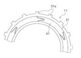
- FIG. 5 is a front partial view of an output side clutch plate according to an embodiment of the present invention. The partially expanded view of the said friction member.
- FIG. 1 shows a torque converter 1 as one embodiment of the present invention.
- OO is a rotational axis of the torque converter 1.
- the torque converter 1 is a device disposed between the engine and the transmission of the vehicle for transmitting torque from the engine to the transmission by fluid.
- the torque converter 1 includes a front cover 2, an impeller 3, a turbine 4, a stator 5, and a lockup clutch device 6.
- the front cover 2 is coupled to a crankshaft of the engine.
- the impeller 3 is disposed on the transmission side of the front cover 2 and constitutes a fluid chamber together with the front cover 2.
- the turbine 4 is disposed opposite to the impeller 3 in the fluid chamber, and constitutes a fluid operation chamber together with the impeller 3.
- the stator 5 is disposed on the inner peripheral side of the impeller 3 and the turbine 4 and rectifies the flow from the turbine 4 to the impeller 3.
- the lockup clutch device 6 is disposed axially between the front cover 2 and the turbine 4 to directly transmit the torque from the front cover 2 to the turbine 4 side or to interrupt the torque transmission.
- the configuration of the torque converter main body including the impeller 3, the turbine 4, and the stator 5 is the same as the conventional configuration, and thus the detailed description will be omitted.
- the lockup clutch device 6 has an input side clutch plate 10, an output side clutch plate 11, a piston 12, and a damper mechanism 13.
- the input-side clutch plate 10 is supported by a support member 15 fixed to the front cover 2 so as to be relatively non-rotatable and axially movable.
- the support member 15 is an annular plate member, and the inner peripheral end is fixed to the side surface of the front cover 2 by welding.
- the outer peripheral portion 15 a of the support member 15 is bent toward the turbine 4 to be formed into a tubular shape.
- a plurality of grooves extending in the axial direction are formed in the cylindrical portion 15a.
- a plurality of teeth are formed on the inner peripheral end of the input side clutch plate 10, and the plurality of teeth are engaged with the groove of the cylindrical portion 15a.
- the details of the input clutch plate 10 will be described later. With such a configuration, the input side clutch plate 10 rotates in synchronization with the front cover 2 and is movable in the axial direction.
- the output side clutch plate 11 is disposed between the front cover 2 and the input side clutch plate 10. A plurality of teeth are formed at the outer peripheral end of the output side clutch plate 11. Although the friction member is fixed to the surface of the output side clutch plate 11 on the front cover 2 side, the friction member is not provided on the surface of the output side clutch plate 11 on the turbine 4 side. The details of the output side clutch plate 11 will be described later.
- the piston 12 is a disk-like member having a hole at its center.
- the piston 12 includes a main body 12a, an inner cylindrical portion 12b formed by bending an inner peripheral portion of the main body 12a toward the transmission, and an outer peripheral cylinder formed by bending an outer peripheral portion of the main body 12a toward the engine And an annular portion 12c.
- the main body 12 a is disposed to face the front cover 2.
- the inner circumferential tubular portion 12 b is supported movably in the axial direction with respect to the turbine hub 20 connected to the inner circumferential end of the turbine 4.
- a seal member 21 is provided on the outer peripheral surface of the turbine hub 20, and the seal member 21 seals between the inner peripheral cylindrical portion 12 b of the piston 12 and the turbine hub 20.
- a plurality of grooves extending in the axial direction are formed in the outer peripheral cylindrical portion 12c, and a plurality of teeth of the output side clutch plate 11 mesh with the plurality of grooves.
- the output clutch plate 11 rotates in synchronization with the piston 12 and is axially movable.
- the damper mechanism 13 has a drive plate 24 and a driven plate 25 and a torsion spring 26 disposed therebetween.
- the drive plate 24 is an annular member, and its inner peripheral end is fixed to the main body 12 a of the piston 12 by rivets 27. Further, at the outer peripheral portion of the drive plate 24, a housing portion 24 a for housing the torsion spring 26 and supporting both ends of the torsion spring 26 is formed.
- the driven plate 25 is fixed to the surface on the front cover 2 side of the turbine shell 4 a constituting the turbine 4. The outer peripheral end of the driven plate 25 is bent toward the front cover 2, and the tip thereof is engaged with the end of the torsion spring 26.
- both of the clutch plates 10, 11 are composed of the core plates 30, 31 and the friction members 40a, 40b, 41 fixed to the core plates 30, 31.
- the input clutch plate 10 has a core plate 30 having a plurality of teeth 30a formed at its inner peripheral end, as shown in FIG.
- the friction members 40a and 40b (only the friction portion 40a on the front side is shown in FIG. 2) are fixed on both sides.
- the output side clutch plate 11 has a core plate 31 having a plurality of teeth 31 a formed on the outer peripheral portion, and a friction member 41 fixed only to the surface of the core plate 31 on the front cover 2 side. And.
- the friction member 40a fixed to the turbine 4 side of the input side clutch plate 10 is formed in a continuous annular shape.
- the friction member 40 a has a plurality of friction portions 51 forming an annular friction surface, and a plurality of grooves 52 formed between the friction portions 51.
- the plurality of friction portions 51 are connected via the bottom of the groove 52, and the plurality of friction portions 51 and the groove 52 are integrally formed by press molding.
- the input-side clutch plate 10 having the friction member 40a rotates in the direction indicated by the arrow R in the figure.
- the groove 52 includes an inner circumferential groove 54 formed on the inner circumferential side, and an outer circumferential groove 55 formed on the outer circumferential side continuously to the inner circumferential groove 54.
- the inner circumferential groove 54 has a V-shaped first groove 57 and a second groove 58 which open in the rotational direction, and a folded groove 59 formed between the grooves 57 and 58.
- the first groove 57 has an opening 57a at the inner peripheral end, and extends from the opening 57a in the direction opposite to the rotational direction R.
- the second groove 58 is continuous with the first groove 57 and extends on the outer peripheral side of the first groove 57 and along the rotational direction.
- the folded groove 59 is formed in a curved shape between the first groove 57 and the second groove 58.
- the circumferential length L (see FIG.
- each of the first groove 57 and the second groove 58 is preferably 3% or more of the circumferential length of the radial central portion of the friction member 40a. . This is to increase the flow path resistance flowing through the grooves 57 and 58 to reduce the amount of leakage.
- the outer peripheral groove 55 is continuous with the outer peripheral end of the second groove 58 and is formed so as to radially extend in the outer peripheral direction. Specifically, as shown in FIG. 4, the outer peripheral groove 55 is formed such that the groove center line of the outer peripheral groove 55 coincides with a line N radially extending from the center of the friction member 40a.
- the outer peripheral groove 55 is preferably formed to be located within a range of ⁇ 20 ° or less with respect to the line N.
- the friction member 41 fixed to the output side clutch plate 11 includes a groove shape, and has the same shape as the friction member 40 a of the input side clutch plate 10.
- the friction member 40b fixed to the front cover 2 side of the input side clutch plate 10 has the same configuration as the other friction members 40a and 41 except that the direction of the groove (direction in which the V opens) is different. is there.
- the above-described friction members 40 a and 40 b are fixed to the input side clutch plate 10, and the friction member 41 is fixed to the output side clutch plate 11. That is, on both surfaces of the input side clutch plate 10, the friction members 40a and 40b are fixed such that the inner circumferential groove 54 has a V-shape that opens in the rotational direction. Further, a friction member 41 is fixed to the surface on the front cover 2 side of the output side clutch plate 11 so that the inner circumferential groove 54 has a V-shape that opens facing the rotational direction.
- the lockup clutch device 6 is turned off (torque transmission is cut off) in order to transmit torque from the engine to the transmission side via fluid.
- hydraulic fluid is supplied to a space A (see FIG. 1) between the front cover 2 and the piston 12 by a control valve not shown, and the hydraulic pressure of this space A is the hydraulic pressure of the space on the turbine 4 side of the piston 12 It is controlled to be higher. Therefore, the piston 12 moves to the transmission side, the input side clutch plate 10 and the output side clutch plate 11 are separated, and the clutch is turned off. Therefore, the torque from the front cover 2 is transmitted to the transmission side via the torque converter main body without passing through the lockup clutch device 6.
- the hydraulic oil flows from the inner peripheral side to the outer peripheral side of both clutch plates 10 and 11. Further, the input side clutch plate 10 rotates in synchronization with the front cover 2 at the same rotational speed as the engine. Further, the output side clutch plate 11 is rotating at a rotation speed lower than that of the stop or input side clutch plate 10.
- the friction members 40a and 40b provided on both sides of the input side clutch plate 10 have the openings 57a at the inner peripheral end of the inner peripheral groove 54 because the inner peripheral groove 54 is opened along the rotational direction.
- the hydraulic oil which is dragged by the rotation of the input side clutch plate 10 flows from the inner peripheral end opening of the friction member 41 of the output side clutch plate 11. Therefore, the working oil is sufficiently supplied to the grooves 52 of the friction members 40a, 40b, 41 of the both clutch plates 10, 11. Therefore, the friction surfaces of both clutch plates 10 and 11 can be sufficiently lubricated and cooled. Moreover, drag torque can be suppressed low.
- the friction member is integrally formed
- the present invention can be similarly applied to a segment type friction member in which a plurality of friction portions are formed separately.
Landscapes
- Engineering & Computer Science (AREA)
- General Engineering & Computer Science (AREA)
- Mechanical Engineering (AREA)
- Mechanical Operated Clutches (AREA)
- Hydraulic Clutches, Magnetic Clutches, Fluid Clutches, And Fluid Joints (AREA)
Abstract
Description
図1は、本発明の一実施形態としてのトルクコンバータ1を示している。O-Oはトルクコンバータ1の回転軸線である。トルクコンバータ1は、車両のエンジンとトランスミッションとの間に配置され、エンジンからのトルクを流体によってトランスミッションに伝達するための装置である。
以下、本発明の一実施形態によるクラッチプレートを含むロックアップクラッチ装置6について詳細に説明する。
入力側クラッチプレート10と出力側クラッチプレート11の基本的構成は同じである。すなわち、両クラッチプレート10,11は、図1、図2及び図3に示すように、コアプレート30,31とコアプレート30,31に固定された摩擦部材40a,40b,41とからなる。具体的には、入力側クラッチプレート10は、図2に一部を拡大して示すように、内周端部に複数の歯30aが形成されたコアプレート30を有し、このコアプレート30の両面に摩擦部材40a,40b(図2では表面側の摩擦部40aのみが表れている)が固定されている。また、出力側クラッチプレート11は、図3に示すように、外周部に複数の歯31aが形成されたコアプレート31と、コアプレート31のフロントカバー2側の面にのみ固定された摩擦部材41と、を有している。
入力側クラッチプレート10のタービン4側に固定された摩擦部材40aは、連続する環状に形成されている。摩擦部材40aは、環状の摩擦面を形成する複数の摩擦部51と、これらの摩擦部51の間に形成された複数の溝52と、を有している。この例では、複数の摩擦部51は溝52の底部を介してつながっており、複数の摩擦部51及び溝52はプレス成形によって一体的に形成されている。なお、図2に示す例では、摩擦部材40aを有する入力側クラッチプレート10は図の矢印Rで示す方向に回転する。
発進時等の低速度時においては、エンジンからのトルクを、流体を介してトランスミッション側に伝達するために、ロックアップクラッチ装置6はオフ(トルク伝達は遮断)される。この場合は、図示しないコントロールバルブにより、フロントカバー2とピストン12との間の空間A(図1参照)に作動油が供給され、この空間Aの油圧がピストン12のタービン4側の空間の油圧より高くなるように制御される。このため、ピストン12はトランスミッション側に移動し、入力側クラッチプレート10と出力側クラッチプレート11とが離れ、クラッチオフとなる。したがって、フロントカバー2からのトルクはロックアップクラッチ装置6を介さずにトルクコンバータ本体を介してトランスミッション側に伝達される。
本発明は以上のような実施形態に限定されるものではなく、本発明の範囲を逸脱することなく種々の変形又は修正が可能である。
2 フロントカバー
3 インペラ
4 タービン
5 ステータ
6 ロックアップクラッチ装置
10 入力側クラッチプレート
11 出力側クラッチプレート
12 ピストン
13 ダンパ機構
40a,40b,41 摩擦部材
51 摩擦部
52 溝
54 内周溝
55 外周溝
57 第1溝
58 第2溝
Claims (6)
- 周方向に並べて設けられ、環状の摩擦面を形成する複数の摩擦部と、
複数の前記摩擦部の間に形成され、内周側から外周側に貫通する複数の溝と、
を備え、
前記複数の溝のそれぞれは、
内周端に開口を有する内周側の第1溝及び前記第1溝に連続する外周側の第2溝からなり、周方向に開くV字状に形成された内周溝と、
前記内周溝の第2溝の外周端に連続し、外周方向に放射状に延びる外周溝と、
を有する、
摩擦部材。 - 前記外周溝は、前記外周溝の溝中心線が、摩擦部材の中心から延びる放射状の線に対して±20°以下の範囲内に位置するように形成されている、請求項1に記載の摩擦部材。
- 前記第1溝及び前記第2溝のそれぞれの周方向の長さは、摩擦部材の径方向中央部の周方向長さの3%以上である、請求項1又は2に記載の摩擦部材。
- 環状のコアプレートと、
前記環状のコアプレートの少なくとも一方の側面に固定された請求項1から3のいずれかに記載の摩擦部材と、
を備えたクラッチプレート。 - 入力側回転体と出力側回転体との間に配置されるクラッチ装置であって、
前記入力側回転体に同期して回転する請求項4に記載の入力側クラッチプレートと、
前記出力側回転体に同期して回転する請求項4に記載の出力側クラッチプレートと、
前記入力側クラッチプレートと前記出力側クラッチプレートを互いに圧接し、あるいは圧接を解除する作動機構と、
を備え、
前記入力側クラッチプレート及び前記出力側クラッチプレートはそれぞれ、環状のコアプレートと、前記環状のコアプレートの少なくとも一方の側面に固定された摩擦部材と、を有し、
前記入力側クラッチプレートは、前記摩擦部材の内周溝が回転方向に沿って開くV字状になるように配置され、
前記出力側クラッチプレートは、前記摩擦部材の内周溝が回転方向に対向して開くV字状になるように配置されている、
クラッチ装置。 - 入力側回転体からのトルクを流体によって出力側回転体に伝達するためのトルクコンバータであって、
前記入力側回転体からのトルクが入力されるフロントカバーと、
前記フロントカバーに固定され、前記フロントカバーとともに流体室を構成するインペラと、
前記流体室内において前記インペラに対向して配置されたタービンと、
前記インペラと前記タービンとの内周部側に配置され、前記タービンから前記インペラに流れる流体の流れを整流するためのステータと、
前記フロントカバーと前記タービンとの軸方向間に配置され、前記フロントカバーからのトルクを前記出力側回転体に伝達及び遮断可能なロックアップクラッチ装置と、
を備え、
前記ロックアップクラッチ装置は、請求項5に記載のクラッチ装置を含み、前記入力側クラッチプレートは前記フロントカバーに同期して回転し、前記出力側クラッチプレートは前記タービンに同期して回転する、
トルクコンバータ。
Priority Applications (4)
| Application Number | Priority Date | Filing Date | Title |
|---|---|---|---|
| DE112012001865.6T DE112012001865T5 (de) | 2011-04-25 | 2012-03-22 | Reibelement, Kupplungsplatte, Kupplungsvorrichtung und Drehmomentwandler |
| CN201280018202.8A CN103459874B (zh) | 2011-04-25 | 2012-03-22 | 摩擦部件、离合器片、离合器装置及扭矩转换器 |
| KR1020137027191A KR101897048B1 (ko) | 2011-04-25 | 2012-03-22 | 마찰 부재, 클러치 플레이트, 클러치 장치, 및 토크 컨버터 |
| US14/007,528 US9151334B2 (en) | 2011-04-25 | 2012-03-22 | Friction member, clutch plate, clutch device and torque converter |
Applications Claiming Priority (2)
| Application Number | Priority Date | Filing Date | Title |
|---|---|---|---|
| JP2011097397A JP5143925B2 (ja) | 2011-04-25 | 2011-04-25 | 摩擦部材、クラッチプレート、クラッチ装置、及びトルクコンバータ |
| JP2011-097397 | 2011-04-25 |
Publications (1)
| Publication Number | Publication Date |
|---|---|
| WO2012147433A1 true WO2012147433A1 (ja) | 2012-11-01 |
Family
ID=47071959
Family Applications (1)
| Application Number | Title | Priority Date | Filing Date |
|---|---|---|---|
| PCT/JP2012/057351 Ceased WO2012147433A1 (ja) | 2011-04-25 | 2012-03-22 | 摩擦部材、クラッチプレート、クラッチ装置、及びトルクコンバータ |
Country Status (6)
| Country | Link |
|---|---|
| US (1) | US9151334B2 (ja) |
| JP (1) | JP5143925B2 (ja) |
| KR (1) | KR101897048B1 (ja) |
| CN (1) | CN103459874B (ja) |
| DE (1) | DE112012001865T5 (ja) |
| WO (1) | WO2012147433A1 (ja) |
Families Citing this family (6)
| Publication number | Priority date | Publication date | Assignee | Title |
|---|---|---|---|---|
| JP2016023754A (ja) * | 2014-07-23 | 2016-02-08 | Nskワーナー株式会社 | 摩擦板及び摩擦板を備えた湿式多板クラッチ |
| EP3321542A4 (en) * | 2015-07-06 | 2019-02-20 | Nok Corporation | FRICTION PULLEY |
| US9915332B1 (en) * | 2016-10-26 | 2018-03-13 | Schaeffler Technologies AG & Co. KG | Motor vehicle clutch assembly including shock absorber for smoothing clutch engagement |
| JP6393355B1 (ja) * | 2017-03-29 | 2018-09-19 | 本田技研工業株式会社 | 制御装置および制御システム |
| KR102631564B1 (ko) | 2018-12-29 | 2024-02-02 | 주식회사 카펙발레오 | 차량용 토크 컨버터 |
| JP7386054B2 (ja) * | 2019-11-13 | 2023-11-24 | 株式会社エクセディ | クラッチディスク及びトルクリミッタ |
Citations (4)
| Publication number | Priority date | Publication date | Assignee | Title |
|---|---|---|---|---|
| JPH06300051A (ja) * | 1993-03-25 | 1994-10-25 | Borg Warner Automot Inc | 摩擦ディスク |
| JPH08135676A (ja) * | 1994-11-07 | 1996-05-31 | Daido Metal Co Ltd | 湿式摩擦部材 |
| JP2000266079A (ja) * | 1999-03-12 | 2000-09-26 | Exedy Corp | 湿式摩擦部材及び摩擦ディスク |
| JP2005351296A (ja) * | 2004-06-08 | 2005-12-22 | Nissan Motor Co Ltd | 摩擦係合装置のフリクションプレート |
Family Cites Families (10)
| Publication number | Priority date | Publication date | Assignee | Title |
|---|---|---|---|---|
| US3999634A (en) * | 1974-01-14 | 1976-12-28 | Howell Industries, Inc. | Pneumatic actuation for disc brake assemblies |
| DE4432624C1 (de) * | 1994-09-14 | 1996-04-04 | Fichtel & Sachs Ag | Hydrodynamischer Drehmomentwandler mit einer Überbrückungskupplung |
| US5771691A (en) * | 1996-10-23 | 1998-06-30 | Borg-Warner Automotive, Inc. | Torque converter having spatially oriented flat turbine blades |
| JP2000192989A (ja) | 1998-12-25 | 2000-07-11 | Exedy Corp | 摩擦部材、ディスク組立体及びトルクコンバ―タ |
| US6247568B1 (en) | 1998-12-25 | 2001-06-19 | Exedy Corporation | Friction member for disk assembly, especially for torque converter |
| JP2001032904A (ja) * | 1999-07-19 | 2001-02-06 | Koyo Seiko Co Ltd | 一方向クラッチと軸受との組立体 |
| DE19957511A1 (de) * | 1999-11-30 | 2001-06-21 | Borg Warner Automotive Gmbh | Lamelle für ein Kraftübertragungsaggregat, zum Beispiel für eine Schaltkupplung |
| EP1371866B1 (de) * | 2002-06-15 | 2010-03-03 | Borgwarner, Inc. | Lamelle für eine Mehrscheibenlamellenkupplung |
| JP2005076759A (ja) * | 2003-09-01 | 2005-03-24 | Nsk Warner Kk | 湿式多板クラッチのフリクションプレート |
| US7827786B2 (en) * | 2007-05-24 | 2010-11-09 | Gm Global Technology Operations, Inc. | Seal assembly for reducing fluid loss from transmission pump |
-
2011
- 2011-04-25 JP JP2011097397A patent/JP5143925B2/ja active Active
-
2012
- 2012-03-22 DE DE112012001865.6T patent/DE112012001865T5/de not_active Ceased
- 2012-03-22 KR KR1020137027191A patent/KR101897048B1/ko active Active
- 2012-03-22 WO PCT/JP2012/057351 patent/WO2012147433A1/ja not_active Ceased
- 2012-03-22 CN CN201280018202.8A patent/CN103459874B/zh active Active
- 2012-03-22 US US14/007,528 patent/US9151334B2/en active Active
Patent Citations (4)
| Publication number | Priority date | Publication date | Assignee | Title |
|---|---|---|---|---|
| JPH06300051A (ja) * | 1993-03-25 | 1994-10-25 | Borg Warner Automot Inc | 摩擦ディスク |
| JPH08135676A (ja) * | 1994-11-07 | 1996-05-31 | Daido Metal Co Ltd | 湿式摩擦部材 |
| JP2000266079A (ja) * | 1999-03-12 | 2000-09-26 | Exedy Corp | 湿式摩擦部材及び摩擦ディスク |
| JP2005351296A (ja) * | 2004-06-08 | 2005-12-22 | Nissan Motor Co Ltd | 摩擦係合装置のフリクションプレート |
Also Published As
| Publication number | Publication date |
|---|---|
| JP5143925B2 (ja) | 2013-02-13 |
| CN103459874B (zh) | 2016-08-17 |
| DE112012001865T5 (de) | 2014-01-30 |
| KR20140018925A (ko) | 2014-02-13 |
| CN103459874A (zh) | 2013-12-18 |
| US9151334B2 (en) | 2015-10-06 |
| JP2012229721A (ja) | 2012-11-22 |
| KR101897048B1 (ko) | 2018-09-10 |
| US20140014461A1 (en) | 2014-01-16 |
Similar Documents
| Publication | Publication Date | Title |
|---|---|---|
| JP5835391B2 (ja) | 発進装置 | |
| US9121485B2 (en) | Torque converter with deflectable seal | |
| JP6332472B2 (ja) | クラッチおよびそれを備えた変速装置 | |
| JP5143925B2 (ja) | 摩擦部材、クラッチプレート、クラッチ装置、及びトルクコンバータ | |
| JP5505558B2 (ja) | 発進装置 | |
| US8932169B2 (en) | Clutch backing plate with fluid drain | |
| US6264018B1 (en) | Lockup device of a torque converter | |
| JP2012215222A (ja) | クラッチ装置およびそれを備えた流体伝動装置 | |
| JP6173814B2 (ja) | クラッチ | |
| JP7051272B2 (ja) | 摩擦締結装置 | |
| JP6130286B2 (ja) | トルクコンバータのロックアップ装置 | |
| JP2016125557A (ja) | クラッチおよびそれを備えた変速装置 | |
| US10082198B2 (en) | Lock-up device for torque converter | |
| JP2016125558A (ja) | 変速装置 | |
| US6286648B1 (en) | Lockup device of a torque converter | |
| JP2008095952A (ja) | 車両の為のクラッチ装置 | |
| JP2015197178A (ja) | 動力伝達装置 | |
| JP5505357B2 (ja) | クラッチ装置およびそれを備えた流体伝動装置 | |
| JP6435855B2 (ja) | クラッチおよびそれを備えた変速装置 | |
| JP6284498B2 (ja) | トルクコンバータ装置 | |
| US20190376591A1 (en) | Fluid transmission device | |
| JP2009024815A (ja) | トルクコンバータ用ステータおよびトルクコンバータ |
Legal Events
| Date | Code | Title | Description |
|---|---|---|---|
| 121 | Ep: the epo has been informed by wipo that ep was designated in this application |
Ref document number: 12775976 Country of ref document: EP Kind code of ref document: A1 |
|
| WWE | Wipo information: entry into national phase |
Ref document number: 14007528 Country of ref document: US |
|
| ENP | Entry into the national phase |
Ref document number: 20137027191 Country of ref document: KR Kind code of ref document: A |
|
| WWE | Wipo information: entry into national phase |
Ref document number: 112012001865 Country of ref document: DE Ref document number: 1120120018656 Country of ref document: DE |
|
| 122 | Ep: pct application non-entry in european phase |
Ref document number: 12775976 Country of ref document: EP Kind code of ref document: A1 |