WO2012147392A1 - Dispositif de traitement de signal, procédé de traitement de signal, et dispositif de disque optique - Google Patents
Dispositif de traitement de signal, procédé de traitement de signal, et dispositif de disque optique Download PDFInfo
- Publication number
- WO2012147392A1 WO2012147392A1 PCT/JP2012/053840 JP2012053840W WO2012147392A1 WO 2012147392 A1 WO2012147392 A1 WO 2012147392A1 JP 2012053840 W JP2012053840 W JP 2012053840W WO 2012147392 A1 WO2012147392 A1 WO 2012147392A1
- Authority
- WO
- WIPO (PCT)
- Prior art keywords
- waveform
- signal
- level
- phase error
- reproduction
- Prior art date
Links
Images


Classifications
-
- G—PHYSICS
- G11—INFORMATION STORAGE
- G11B—INFORMATION STORAGE BASED ON RELATIVE MOVEMENT BETWEEN RECORD CARRIER AND TRANSDUCER
- G11B20/00—Signal processing not specific to the method of recording or reproducing; Circuits therefor
- G11B20/10—Digital recording or reproducing
- G11B20/10009—Improvement or modification of read or write signals
- G11B20/10222—Improvement or modification of read or write signals clock-related aspects, e.g. phase or frequency adjustment or bit synchronisation
-
- G—PHYSICS
- G11—INFORMATION STORAGE
- G11B—INFORMATION STORAGE BASED ON RELATIVE MOVEMENT BETWEEN RECORD CARRIER AND TRANSDUCER
- G11B20/00—Signal processing not specific to the method of recording or reproducing; Circuits therefor
- G11B20/10—Digital recording or reproducing
-
- G—PHYSICS
- G11—INFORMATION STORAGE
- G11B—INFORMATION STORAGE BASED ON RELATIVE MOVEMENT BETWEEN RECORD CARRIER AND TRANSDUCER
- G11B20/00—Signal processing not specific to the method of recording or reproducing; Circuits therefor
- G11B20/10—Digital recording or reproducing
- G11B20/10009—Improvement or modification of read or write signals
- G11B20/10037—A/D conversion, D/A conversion, sampling, slicing and digital quantisation or adjusting parameters thereof
-
- G—PHYSICS
- G11—INFORMATION STORAGE
- G11B—INFORMATION STORAGE BASED ON RELATIVE MOVEMENT BETWEEN RECORD CARRIER AND TRANSDUCER
- G11B20/00—Signal processing not specific to the method of recording or reproducing; Circuits therefor
- G11B20/10—Digital recording or reproducing
- G11B20/10009—Improvement or modification of read or write signals
- G11B20/10046—Improvement or modification of read or write signals filtering or equalising, e.g. setting the tap weights of an FIR filter
- G11B20/10055—Improvement or modification of read or write signals filtering or equalising, e.g. setting the tap weights of an FIR filter using partial response filtering when writing the signal to the medium or reading it therefrom
- G11B20/1012—Improvement or modification of read or write signals filtering or equalising, e.g. setting the tap weights of an FIR filter using partial response filtering when writing the signal to the medium or reading it therefrom partial response PR(1,2,2,2,1)
-
- G—PHYSICS
- G11—INFORMATION STORAGE
- G11B—INFORMATION STORAGE BASED ON RELATIVE MOVEMENT BETWEEN RECORD CARRIER AND TRANSDUCER
- G11B20/00—Signal processing not specific to the method of recording or reproducing; Circuits therefor
- G11B20/10—Digital recording or reproducing
- G11B20/10009—Improvement or modification of read or write signals
- G11B20/10222—Improvement or modification of read or write signals clock-related aspects, e.g. phase or frequency adjustment or bit synchronisation
- G11B20/1024—Improvement or modification of read or write signals clock-related aspects, e.g. phase or frequency adjustment or bit synchronisation wherein a phase-locked loop [PLL] is used
-
- G—PHYSICS
- G11—INFORMATION STORAGE
- G11B—INFORMATION STORAGE BASED ON RELATIVE MOVEMENT BETWEEN RECORD CARRIER AND TRANSDUCER
- G11B20/00—Signal processing not specific to the method of recording or reproducing; Circuits therefor
- G11B20/10—Digital recording or reproducing
- G11B20/10009—Improvement or modification of read or write signals
- G11B20/10268—Improvement or modification of read or write signals bit detection or demodulation methods
- G11B20/10277—Improvement or modification of read or write signals bit detection or demodulation methods the demodulation process being specifically adapted to partial response channels, e.g. PRML decoding
-
- G—PHYSICS
- G11—INFORMATION STORAGE
- G11B—INFORMATION STORAGE BASED ON RELATIVE MOVEMENT BETWEEN RECORD CARRIER AND TRANSDUCER
- G11B20/00—Signal processing not specific to the method of recording or reproducing; Circuits therefor
- G11B20/10—Digital recording or reproducing
- G11B20/10009—Improvement or modification of read or write signals
- G11B20/10305—Improvement or modification of read or write signals signal quality assessment
- G11B20/10462—Improvement or modification of read or write signals signal quality assessment consistency with a reference waveform in a given time period, e.g. by calculating correlations or mean square errors
-
- G—PHYSICS
- G11—INFORMATION STORAGE
- G11B—INFORMATION STORAGE BASED ON RELATIVE MOVEMENT BETWEEN RECORD CARRIER AND TRANSDUCER
- G11B20/00—Signal processing not specific to the method of recording or reproducing; Circuits therefor
- G11B20/10—Digital recording or reproducing
- G11B20/14—Digital recording or reproducing using self-clocking codes
-
- G—PHYSICS
- G11—INFORMATION STORAGE
- G11B—INFORMATION STORAGE BASED ON RELATIVE MOVEMENT BETWEEN RECORD CARRIER AND TRANSDUCER
- G11B2220/00—Record carriers by type
- G11B2220/20—Disc-shaped record carriers
- G11B2220/25—Disc-shaped record carriers characterised in that the disc is based on a specific recording technology
- G11B2220/2537—Optical discs
Definitions
- the present invention provides a signal processing device that generates binarized data by performing a process using a PRML (partial response maximum likelihood) partial reproduction signal on a reproduction signal of a recording medium on which binary data is recorded.
- the present invention also relates to a signal processing method and an optical disc apparatus having the signal processing device.
- Increasing the capacity of various optical discs reduces the size of recording marks (including pits) that are binary data formed on the tracks of the optical disc, shortens the wavelength of laser light used for recording and reproduction, and This has been achieved by employing an objective lens having a large numerical aperture to reduce the focused spot size at the focal plane.
- the thickness of the disc substrate serving as a light transmission layer is about 1.2 [mm]
- the laser light wavelength is about 780 [nm]
- the numerical aperture of the objective lens is 0.45.
- the recording capacity is 650 [MB].
- the resolution of the pit for recording a signal is limited by the diffraction limit.
- the thickness of the light transmission layer is about 0.6 [mm]
- the laser light wavelength is about 650 [nm]
- the NA is 0.6
- the recording capacity is 4.7. [GB].
- the diffraction limit of DVD can be calculated from the same formula as in the case of CD, and is about 270 [nm].
- the shortest data length is about 400 [nm]
- the shortest data length is about 1.48 times the focused spot size.
- the thickness of the light transmission layer is 0.1 [mm]
- the laser light wavelength is about 405 [nm]
- the NA is 0.85
- recording per recording layer is performed.
- the capacity is 25 [GB].
- the diffraction limit of BD can be calculated from the same formula as in the case of CD, and is about 120 [nm].
- the shortest data length is about 150 [nm]
- the shortest data length is about 1.25 times the focused spot size.
- the optical disk not only reducing the focused spot, but also the ratio of the size of the shortest data length (shortest pit length) to the focused spot size (approximately 1.93 times for CD, The capacity is increased by reducing 1.25). In order to lower this ratio, it is necessary to lower the SNR (Signal to Noise Ratio) required for the read reproduction signal.
- SNR Signal to Noise Ratio
- a PRML system has been developed that combines a known partial response characteristic of a reproduced waveform of an optical disk and a maximum likelihood estimation method using a Viterbi decoding system. Contributes greatly to improvement.
- a PRML system in which the partial response class is (1, 2, 2, 1) is generally used.
- Class (1, 2, 2, 1) expresses optical response (intersymbol interference) to recorded binary data with 7 gradations (amplitude level), which can be expressed close to the actual reproduced waveform. become.
- the binary data recorded on the BD is estimated by deriving an ideal optical response close to the reproduced waveform using the maximum likelihood estimation method (Viterbi decoding method).
- the shortest data length (shortest pit length) is about 200 [nm], which is smaller than the diffraction limit of about 270 [nm]. Therefore, in the case of HD DVD, the partial response class is set to (1, 2, 2, 2, 1), and the optical response (intersymbol interference) to the recorded binary data is expressed in 9 gradations (amplitude level). By doing so, the shortest data (shortest pit) can be read.
- the role of signal processing is increasing for increasing the capacity of optical disks.
- Non-Patent Documents 1 and 2 disclose an optical super-resolution method called Super-RENS (Super Resolution Solution Field Structure).
- the optical intensity of the condensing lens which is an optical element of the optical disc device, is changed by introducing a refractive index change in a local portion where the optical intensity in the condensing spot is high or the temperature is high on the optical disc.
- a recording mark smaller than the diffraction limit ⁇ / (4 ⁇ NA) determined from the wavelength ⁇ can be reproduced.
- a local portion where the refractive index change occurs is simply called an aperture.
- This opening is excited by energy and is due to a change in refractive index accompanying a change in crystal structure, and therefore there is a time delay with respect to the response of light. If this delay is not negligible with respect to the rotation speed of the optical disk, the signal read by the near-field light is partially delayed, which adversely affects signal decoding and clock signal extraction.
- an optical disc apparatus employs a method of extracting a clock signal from a reproduction signal itself using a PLL (Phase-Locked Loop) circuit.
- a PLL circuit generally includes a phase comparator, a loop filter, and a voltage controlled oscillator. The phase comparator compares the phase calculated from the reproduction signal sampled by the clock signal with the phase of the clock signal itself, and outputs a phase error signal corresponding to the phase difference between them.
- the loop filter supplies a control voltage obtained by filtering the phase error signal from the phase comparator to the voltage controlled oscillator.
- the voltage controlled oscillator outputs a clock signal having a frequency proportional to the control voltage. Since the reproduction signal is sequentially sampled by the output clock signal from the voltage controlled oscillator, and the output clock signal from the voltage controlled oscillator affects the calculation of the phase of the reproduction signal, the PLL circuit constitutes a loop feedback circuit. By this loop feedback circuit, the frequency and phase difference of the output clock signal change following the frequency of the input signal.
- a point (cross point) where the reproduction signal crosses a certain slice level is set as a clock point.
- the difference between the cross point and the sampling point becomes a phase error between the reproduction signal (reproduction waveform) and the clock signal, and the loop feedback circuit works so as to make them coincide.
- the slice level the center level (average level) of the reproduction waveform is generally used, and in the reproduction waveform of the optical disc, the cross point is the highest.
- Non-Patent Documents 1 and 2 cannot exhibit the effect on a reproduced signal (reproduced waveform) with a significant waveform deterioration.
- the SNR decreases as the data length (record mark length) of recorded binary data (record mark) becomes shorter, and the amplitude level of the reproduced waveform of binary data with a shorter data length becomes the center level.
- the variation in the phase error becomes large, the clock signal becomes unstable, and the reproduction signal
- the quality of the binarized data is reduced.
- Patent Document 1 when a predicted waveform (ideal waveform) predicted by the PRML method is used as a target waveform, the target waveform itself includes an error, and a phase error is calculated with reference to the target waveform including the error. Resulting in. For this reason, the technique disclosed in Patent Document 1 has a problem in that the variation in phase error becomes large, the clock signal becomes unstable, and the quality of the binarized data as a reproduction signal decreases.
- the present invention has been made to solve the above-described problems of the prior art, and an object of the present invention is to improve the quality of binarized data as a reproduction signal by generating a stable clock signal.
- a signal processing apparatus, a signal processing method, and an optical disc apparatus are provided.
- a signal processing apparatus uses an adaptive filter that adaptively filters the reproduction waveform so that the reproduction waveform of the reproduction signal from the recording medium approaches a target waveform, and a PRML method,
- the binarized data is sequentially generated from the filtered reproduction waveform by sampling at the sampling point of the period based on the clock signal, and the partial response waveform as the target waveform is sequentially generated from the binarized data.
- a PRML circuit a calculation unit that sequentially calculates a first phase error for the sampling point from a difference between the target waveform and the reproduction waveform subjected to the filtering; and a specific phase error from the first phase error.
- a limiting unit that outputs a second phase error by excluding, and a frequency before the second phase error.
- a clock generator for generating a clock signal the specific phase error is characterized in that it comprises a phase error when the partial response waveform becomes a certain level.
- the signal processing method includes a step of adaptively filtering the reproduction waveform so that the reproduction waveform of the reproduction signal from the recording medium approaches a target waveform, and using the PRML method, the filtering Sequentially generating binarized data from the reproduced waveform subjected to the processing by sampling at a sampling point of a period based on a clock signal, and sequentially generating a partial response waveform as the target waveform from the binarized data; Sequentially calculating a first phase error for the sampling point from the difference between the target waveform and the filtered reproduction waveform, and excluding a specific phase error from the first phase error A step of outputting a second phase error; and generating the clock signal having a frequency corresponding to the second phase error.
- said specific phase error is characterized in that reproduction waveform the filtering has been performed a phase error for the nearest sampling points to the cross point intersecting the average level of the reproduced waveform.
- the signal processing method includes a step of adaptively filtering the reproduction waveform so that the reproduction waveform of the reproduction signal from the recording medium approaches a target waveform, and using the PRML method, Sequentially generating binarized data from the filtered reproduced waveform by sampling at a sampling point of a period based on a clock signal, and sequentially generating a partial response waveform from the binarized data; and the partial response
- An optical head device that optically reads binary data recorded on a recording medium, and a reproduction signal processing unit that generates a reproduction signal from a signal output from the optical head device. And the signal processing device for generating the binarized data from the reproduction signal.
- the signal processing device the signal processing method, and the optical disc apparatus according to the present invention, it is possible to generate a stable clock signal, and as a result, it is possible to improve the quality of binary data as a reproduction signal. There is an effect.
- FIG. 1 is a diagram schematically showing a configuration of an optical disc apparatus in which a signal processing apparatus according to Embodiments 1 to 3 of the present invention can be mounted. It is a block diagram which shows roughly the structure of the signal processing apparatus of the 1st reference example.
- FIG. 3 is a block diagram schematically showing an example of a configuration of a PLL circuit shown in FIG. 2. It is a figure which shows the calculation method of the phase error using the slice level in a PLL circuit. It is a block diagram which shows roughly the structure of the signal processing apparatus of the 2nd reference example.
- 1 is a block diagram schematically showing a configuration of a signal processing device according to a first embodiment.
- FIG. 1 It is a figure which shows the example of the reproduction
- FIG. 5 is a block diagram schematically showing a configuration of a signal processing device according to a second embodiment.
- FIG. 10 is a block diagram schematically showing a configuration of a signal processing device according to a modification of the second embodiment.
- FIG. 10 is a block diagram schematically showing a configuration of a signal processing device according to a third embodiment.
- FIG. 1 includes the signal processing device 30 according to the first embodiment (or the signal processing device 40 according to the second embodiment or the signal processing device 50 according to the third embodiment). It is a figure which shows schematically the structure of the optical disk apparatus 60 which is a possible reproducing
- the optical disc device 60 optically reads binary data (record marks) recorded on the information recording layer of the optical disc 60 that is a recording medium such as a CD, DVD, BD, etc., and records the recorded binary data. This is a device having a function of outputting binarized data as a reproduction signal.
- the optical disc device 60 is such that the binarized data output as the reproduction signal does not differ from the binary data actually recorded on the optical disc 70. (To be close).
- the optical disc device 60 irradiates a laser beam to the spindle motor 61 for rotating the optical disc 70 mounted on the turntable and the information recording layer of the optical disc 70, and the information recording layer And an optical head device 62 that receives the reflected return light beam and outputs a signal.
- the optical disc device 60 also includes a sled motor 63 that is a driving means for moving the optical head device 62 in the radial direction Dr of the optical disc 70, a laser control circuit 64, a modulation circuit 65, a servo control unit 66, and a reproduction unit.
- a signal processing unit 67, a RAM (Random Access Memory) 68, and an MPU (Micro Processing Unit) 69 are provided.
- FIG. 1 the optical disc device 60 irradiates a laser beam to the spindle motor 61 for rotating the optical disc 70 mounted on the turntable and the information recording layer of the optical disc 70, and the information recording layer And an optical head device 62 that receives the reflected return light beam
- one-way or two-way arrows connecting the constituent elements indicate a typical flow path and direction of signals or information between the constituent elements of the optical disc apparatus 60. It does not indicate all the connection relationships between them, nor does it indicate all the directions of information flow.
- the servo controller 66 includes a spindle motor control circuit 661 that controls the operation of the spindle motor 61, an optical head control circuit 662 that controls the operation of the optical head device 62, and a thread motor control circuit 663 that controls the operation of the thread motor 63. And have. These control circuits 661, 662, 663 operate based on a command signal output from the MPU 69.
- the reproduction signal processing unit 67 detects a reproduction signal based on a signal detected by the optical head device 62 and sent via the transmission line L3, and a transmission line L1 by detecting the reproduction signal.
- a reproduction signal detection circuit 673 that outputs as an output signal, and a wobble signal detection circuit 671 that detects a wobble signal obtained by reflected light from the meandering guide track groove of the optical disk 70.
- the RAM 68 has a program area 681 and a data area 682.
- the MPU 69 controls the operation of each unit in accordance with the program recorded in the RAM 68 and determines the control content based on the signal sent from each unit.
- the MPU 69 is an optical disk device based on an output signal sent via the transmission line L2 such as signal amplitude value data and status signal detected by the reproduction signal detection circuit 673, or other output signals sent from each unit.
- the operation of the entire 60 is determined, and control data (for example, a signal on the transmission line L2 from the MPU 69 to the reproduction signal detection circuit 673) is transmitted to each unit to control each unit.
- control data for example, a signal on the transmission line L2 from the MPU 69 to the reproduction signal detection circuit 673
- the optical head control circuit 662 outputs a control signal based on the servo error signal SE sent from the servo signal detection circuit 672 and the operation command (command signal) from the MPU 69 to the optical head device 62 via the transmission line L4, thereby producing an optical head.
- the light emitted from the head device 62 onto the optical disk 70 is controlled.
- the thread motor control circuit 663 controls the operation of the thread motor 63 based on the servo error signal SE sent from the servo signal detection circuit 672 and the operation command from the MPU 69.
- the spindle motor control circuit 661 controls the operation of the spindle motor 61 based on the servo error signal SE sent from the servo signal detection circuit 672 and the operation command from the MPU 69.
- the signal processing device 30 receives the reproduction signal (first reproduction signal) from the reproduction signal detection circuit 672 through the transmission line L1, and demodulates binary data (second reproduction signal) from the reproduction signal.
- Part of the data output from the MPU 69 is converted into a recording signal suitable for recording on the optical disk 70 by the modulation circuit 65 and sent to the laser control circuit 64.
- the laser control circuit 64 controls the light emission power of the semiconductor laser mounted on the optical head device 62 by sending a control signal based on the recording signal from the modulation circuit 65 to the optical head device 62 via the transmission line L5. To do.
- the optical head device 62 operates based on a control signal from the laser control circuit 64 and condenses the light beam from the semiconductor laser on the optical disc 70.
- the optical head device 62 receives the return light beam reflected by the information recording layer of the optical disc 70 and performs detection for generating a reproduction signal and a servo signal.
- FIG. 2 is a block diagram schematically showing the configuration of the signal processing apparatus 10 of the first reference example.
- the signal processing apparatus 10 of the first reference example is an example of an apparatus that can be used in place of the signal processing apparatus 30 in the optical disc apparatus 60 shown in FIG.
- the signal processing apparatus 10 of the first reference example generates binarized data, which is a reproduction signal after signal processing, from the reproduction signal input from the reproduction signal detection circuit 673 through the transmission line L1. As shown in FIG.
- the signal processing apparatus 10 of the first reference example includes an A / D (analog / digital) conversion circuit 11, a digital amplifier 12, a pre-equalizer 13, an adaptive filter 14, and PRML.
- the circuit 15 includes an adder (subtracter) 18 as a phase error calculation unit, and a PLL circuit 19.
- the PRML circuit 15 generates a partial response waveform from the Viterbi decoding circuit 16 that performs processing based on the maximum likelihood estimation method on the signal output from the adaptive filter 14 and the binarized data output from the Viterbi decoding circuit 16.
- a PR (Partial Response) decoder 17 a PR (Partial Response) decoder 17.
- the A / D conversion circuit 11 converts the input reproduction signal into a digital value.
- the PLL circuit 19 generates a clock signal synchronized with the digitized reproduction signal from the A / D conversion circuit 11 and supplies the clock signal to each component of the signal processing device 10 including the A / D conversion circuit 11.
- the digital amplifier 12 adjusts the digitized reproduction signal from the A / D conversion circuit 11 to a desired amplitude level. If the digital amplifier 12 is an AGC (Auto Gain Control) circuit and automatically adjusts so that the amplitude level becomes a constant value, fluctuations in the amplitude level of the reproduced signal due to fluctuations in the reflected light from the optical disc 70, etc. Can be ignored in subsequent circuits.
- AGC Automatic Gain Control
- the pre-equalizer 13 amplifies mainly the high frequency component around the shortest data length in the waveform of the reproduction signal aligned to a desired amplitude level. Due to the MTF (Modulation Transfer Function) characteristics of light, the high-frequency component around the shortest data length tends to become extremely small, so the high-frequency component around the shortest data length is amplified to some extent, making it easy to process in the subsequent filter Become.
- MTF Modulation Transfer Function
- the adaptive filter 14 is used in combination with the PRML circuit 15 at the subsequent stage, and performs filter processing using the ideal reproduction waveform estimated by the PRML circuit 15 as a target waveform.
- This ideal reproduction waveform is output from the PR decoder 17 as a predicted waveform.
- the adaptive filter 14 As a typical adaptive algorithm used by the adaptive filter 14, for example, there is an LMS (Least Mean Square) algorithm.
- the input signal data at time n is x (n)
- the coefficient at the filter tap k (kth tap) is w k (n)
- the filter coefficient update step is ⁇
- the error signal is e
- the updated coefficient w k (n + 1) is expressed by the following equation (1). Note that k and n are each a positive integer.
- w k (n + 1) w k (n) + 2 ⁇ ⁇ ⁇ e (n) ⁇ x (n) (1)
- the error signal e (n) is represented by the following equation (2), where y (n) is the data string of the reproduced waveform after filtering and d (n) is the data string of the target waveform.
- e (n) d (n) -y (n) (2)
- the adaptive algorithm used by the adaptive filter 14 another algorithm such as a normalized LMS algorithm, an RMS (Recursive Last Square) algorithm, or a projection algorithm may be used.
- FIG. 3 is a block diagram showing a general configuration of the PLL circuit 19 shown in FIG.
- the PLL circuit 19 includes a phase comparator 191, a loop filter 192, and a voltage controlled oscillator 193.
- the phase comparator 191 compares the phase calculated from the reproduction signal sampled by the clock signal with the phase of the clock signal itself, and outputs a phase error signal corresponding to the phase difference.
- the loop filter 192 filters the phase error signal from the phase comparator 191 and supplies it to the voltage controlled oscillator 193 as a control voltage.
- the voltage controlled oscillator 193 outputs a clock signal having a frequency proportional to the received control voltage to each component as an output clock signal.
- the PLL circuit 19 constitutes a loop feedback circuit that sequentially samples the reproduction signal based on the output clock signal. As a result, the frequency and phase difference of the output clock signal change following the frequency of the input signal.
- the signal modulation method is 1-7 RLL (Run Length Limit) modulation
- the length of one cycle (one clock cycle) of the clock signal output from the PLL circuit 19 is T
- the length of the reproduction signal is The range is from 2T (shortest data length) to 8T.
- FIG. 4 is a diagram showing a method for calculating the phase error using the slice level in the PLL circuit 19.
- a cross point where a reproduction signal (reproduction waveform) and a certain slice level intersect with a rising or falling point of a clock signal are compared.
- the phase comparator 191 detects sampling points P1 and P2 (points indicated by black circles P1 and P2 in FIG. 4) before and after the point where the slice level and the reproduction waveform intersect, and uses linear approximation.
- a cross point Tc is calculated by using the ratio of potentials at two points by interpolation, and a time interval between the cross point Tc and the sampling point P1 is calculated as a phase error Ep.
- a zero level (0 level) that is the center level (average level) of the reproduced waveform is generally used.
- a method of making the slice level variable so that the offset amount is canceled may be employed.
- the phase error Ep obtained from the slice level and the sampling points P1 and P2 is obtained.
- the influence of jitter noise tends to increase as the data length (record mark length) of binary data (record mark) recorded on a recording medium is shorter.
- the amplitude level of a reproduced waveform generated by reproducing binary data having a short data length is concentrated near the slice level, and thus a reproduced signal of binary data having a short data length is particularly greatly affected by jitter noise.
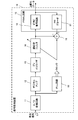
- FIG. 5 is a block diagram schematically showing the configuration of the signal processing device 20 of the second reference example.
- the signal processing device 20 of the second reference example is a device that is less susceptible to jitter noise, which is a problem in the signal processing device 10 of the first reference example.
- the signal processing device 20 of the second reference example is a device that can be used in place of the signal processing device 30 in the optical disk device 60 shown in FIG.
- the same or corresponding components as those shown in FIG. 2 (the signal processing apparatus 10 of the first reference example) are denoted by the same reference numerals.
- phase error is generated from the reproduction signal sequentially sampled by the A / D conversion circuit 11, and a control voltage based on this phase error is generated.
- the clock generation circuit 29 that generates and outputs a clock signal having a frequency proportional to the control voltage changes the frequency and phase difference of the clock signal following the frequency of the input reproduction signal. Therefore, when a reproduction signal having a large jitter noise is input to the signal processing apparatus 10 of the first reference example, the influence of the jitter noise also affects the slice level and the phase error obtained from the sampling points P1 and P2. As a result, the clock signal generated by the PLL circuit 19 becomes unstable.
- the estimation is performed by the PRML method without using the slice level used in the signal processing device 10 (FIG. 2) of the first reference example.
- a clock signal is generated using a phase error S3 between the partial response waveform S2 that is the predicted signal (predicted waveform) and the reproduced signal (reproduced waveform) S1.
- the signal processing device 20 of the second reference example shown in FIG. 5 is a part of the configuration of the PLL circuit 19 of the signal processing device 10 (FIG. 2) of the first reference example, that is, a loop filter.
- a clock generation unit 29 including 192 and a voltage controlled oscillator 193 is included.
- the signal processing device 20 of the second reference example may include a PLL circuit 19.
- the loop filter 192 and the voltage controlled oscillator 193 in the PLL circuit 19 are connected to the phase comparator 191.
- a configuration (for example, a switch circuit) that can be used separately is required.
- the phase error S3 is input to the clock generation unit 29, the loop filter 192 generates a control voltage based on this phase error signal, and the voltage controlled oscillator 193 A clock signal with a frequency proportional to is output. Then, the signal processing device 20 of the second reference example calculates the phase error S3 between the partial response waveform S2 and the reproduction waveform S1 estimated by the PRML method at all sampling points. According to the signal processing device 20 of the second reference example, the clock generation unit 29 generates the clock signal using the phase error S3 for all the sampling points. A stable clock signal can be obtained.
- the signal processing device 20 of the second reference example since the phase error S3 is obtained using the partial response waveform S2 that is a predicted waveform by the PRML method, if the partial response waveform S2 itself contains many errors, an error is generated.
- the phase error S3 including a large amount is calculated, and the clock signal generated by the clock generation unit 29 is unstable.
- the signal processing device 20 of the second reference example can generate a stable clock signal when the error rate of the input reproduction signal is below a certain level.
- it is not rare that a playback waveform with a high error rate is input, and a signal processing method that can generate a stable clock signal even when a playback waveform with a high error rate is input is adopted.
- a signal processing apparatus is required.
- ⁇ 1-4 Configuration of Signal Processing Device 30 According to Embodiment 1
- the signal processing device 30 according to Embodiment 1 is problematic in the signal processing device 10 of the first reference example shown in FIG.
- the clock signal becomes unstable due to a large jitter noise in the case of FIG. 5 and a problem in the signal processing apparatus 20 of the second reference example shown in FIG. 5 (when a reproduction waveform having a high error rate is input, the clock signal is not stable).
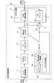
- FIG. 6 is a block diagram schematically showing a configuration of the signal processing device 30 according to the first embodiment (that is, a device capable of performing the signal processing method according to the first embodiment).
- the signal processing device 30 according to the first embodiment can constitute a part of the optical disc device 60 shown in FIG.
- the signal processing device 30 according to the first embodiment is different from the signal processing device 20 (FIG. 5) of the second reference example in that it includes a selector 37 as a limiting unit that limits the output phase error S13.
- the signal processing apparatus 30 uses an adaptive filter 14 that adaptively filters the reproduction waveform so that the reproduction waveform of the reproduction signal from the recording medium approaches the target waveform, and the PRML method.
- PRML that sequentially generates binarized data from the reproduced waveform S11 subjected to filtering by sampling at a sampling point of a period based on a clock signal and sequentially generates a partial response waveform S12 that becomes a target waveform from the binarized data.
- the specific phase error includes the phase error for the sampling point closest to the cross point where the filtered reproduction waveform S11 crosses the average level of the reproduction waveform S11.
- the selector 37 desirably sets the number of second phase errors S14 to be equal to or greater than the number of cross points where the filtered reproduction waveform S11 crosses the average level of the reproduction waveform S11.
- the specific phase error includes a phase error when the partial response waveform S12 reaches a specific level.
- the specific level is, for example, (1) the first level obtained by reproducing binary data having the shortest data length on the recording medium, and (2) the second shortest data length on the recording medium. This is any one of the second level obtained by the reproduction of the binary data, (3) both the first level and the second level.
- the PRML circuit 15 sets the class of the partial response waveform S12 to (1, 2, 2, 2, 1), and the specific level is, for example, 0 level, which is the level of the center point of the partial response waveform S12, and 0 It is desirable that the level includes a ⁇ 1 level that is a level adjacent to the level and a ⁇ 2 level that is a level adjacent to the ⁇ 1 level.
- the selector 37 in the signal processing device 30 checks the amplitude level of the partial response waveform S12 that is a predicted waveform output from the PR decoder 17 at each timing of the clock signal. , Whether to output the phase error S13 to the loop filter 192 (shown in FIG. 5) of the clock generation unit 29 is selected. For example, the selector 37 confirms the amplitude level of the partial response waveform S12 (for example, a table (storage unit) that stores a reference value for amplitude level selection) and the comparison result, and based on the comparison result. And a comparison / selection circuit that selects whether or not to output the phase error S13 to the loop filter 192 of the clock generation unit 29.
- a table storage unit
- the signal processing device 30 suppresses the increase in the calculation amount and the circuit scale as much as possible, and the amplitude of the partial response waveform S12 output from the PR decoder 17 at each timing of the clock signal.
- a function of confirming the level and selecting whether or not to output the phase error S13 to the loop filter 192 of the clock generation unit 29 can be realized.
- ⁇ 1-5 Effects of First Embodiment
- the signal processing method, and the optical disc device 60 according to the first embodiment a stable clock signal can be generated, and as a result, reproduction There is an effect that the quality of the binarized data as a signal can be improved.
- the selector only needs to be equipped with a level selection table and a comparison selection circuit. There is also an effect that the amount of scale increase is extremely small.
- ⁇ 1-6 Reasons for Obtaining the Effect of the First Embodiment
- the signal processing device 30 according to the first embodiment limits the error level (level point) of the reproduction signal used for calculating the phase error, thereby reducing the error rate. Even when the waveform is high, a stable clock signal can be obtained. As described in the description of the first reference example, the jitter noise tends to increase as the reproduction signal of binary data having a shorter data length (for example, a recording mark (pit) recorded on an optical disc).
- the phase error it is effective to exclude the sampling points near the center level of the reproduction signal and calculate the phase error from the data of the sampling points that are not excluded. For example, in calculating the phase error, it is effective to exclude the amplitude level data related to the signal having the shortest data length (ie, 2T) (2T signal) and calculate the phase error from the amplitude level data not excluded. It is.
- the amplitude level data and the signal having the second shortest data (ie, 3T) ie, the 3T signal
- the amplitude level data and the signal having the second shortest data are related to the signal (2T signal) having the shortest data length (ie, 2T). It is effective to exclude the amplitude level data regarding and to calculate the phase error from the amplitude level data not excluded.
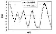
- the solid line is, for example, the waveform of the reproduction signal S11 output from the adaptive filter 14, and the dotted line is the predicted waveform (target waveform of the adaptive filter 14) output from the PR decoder 17.
- the error signal tends to increase as the signal has a shorter data length, that is, as the amplitude level of the reproduction signal is closer to the center level (0 level in FIG. 7). From FIG. 7, it can be considered that it is desirable to exclude a signal having a shorter data length, that is, a signal whose amplitude level of the reproduction signal is closer to the center level (0 level in FIG. 7) from the calculation of the error signal.
- FIG. 8 shows a case where (1, 2, 2, 2, 1) is used as the partial response class and the error rate is 6E-3 in the signal processing device 20 (FIG. 5) of the second reference example. It is a figure which shows the example of the error distribution (statistic result of the error with respect to the data length of a reproduction
- FIG. 8 shows signals of data lengths 2T, 3T,..., 9T recorded on the optical disc, signals of data lengths 2T to 3T (denoted as “2T-3T”),. For signals up to 9T (denoted as “2T-9T”), the number of samples, the number of errors, the error rate, and the occupation ratio are shown.
- the number of samples of the signal having the data length 2T-9T is the total number of samples
- the number of errors of the signal having the data length 2T-9T is the total number of errors.
- the occupation ratio is a value obtained by dividing the number of errors by the total number of errors. From the columns of data lengths 2T, 3T,..., 9T in FIG. 8, the number of errors in the data length 2T signal (“88” in FIG. 8) and the number of errors in the data length 3T signal (“102” in FIG. 8) However, the number of errors in signals of other data lengths (4T, 5T, 6T, 7T, 8T, and 9T) ("12, 8, 4, 4, 1, 0" in FIG. 8) is extremely large. Recognize. From the statistical result of FIG.
- FIG. 9 shows a case where (1, 2, 2, 2, 1) is used as the partial response class and the error rate is 6E-3 in the signal processing device 20 (FIG. 5) of the second reference example. It is a figure which shows the example of distribution of each amplitude level of a reproduction
- FIG. 10 shows a case where (1, 2, 2, 2, 1) is used as the partial response class and the error rate is 6E-3 in the signal processing device 20 (FIG. 5) of the second reference example. It is a figure which shows the example of data length distribution (probability which each data length in each level can take) in the signal processing apparatus 20 as a table
- the probability shown in FIG. 10 is a value obtained by rounding off after the decimal point.
- the total of the points at which the amplitude level of the reproduced waveform is 0 is 100%. As shown in FIG.
- the amplitude level having a large proportion of the signals having the data lengths 2T and 3T is a level range from the amplitude level 0 to the amplitude level ⁇ 3 (that is, amplitude levels ⁇ 3, ⁇ 2, ⁇ 1, 0, +1, +2, +3).
- the dispersion is relatively large in the level range from amplitude level 0 to amplitude level ⁇ 3. Therefore, it can be seen that errors in signals with data lengths 2T and 3T have a large influence on the dispersion.
- the data length 2T (shortest data length) and the data length 3T (second shortest data length) are used. It can be considered that it is desirable to calculate the phase error using the signal at the amplitude level ⁇ 4, excluding the level range from the amplitude level 0 to the amplitude level ⁇ 3, in which the ratio of the signal is large.
- the number of samples is approximately 48% (when using the data at the amplitude level 0) ( That is, the value decreases to 24% of the amplitude level +4 and 24% of the amplitude level 4 in the row of the data length 2T-9T in FIG. Since the number of samples is equal to the rate at which the phase error is calculated, the loop gain is reduced and a stable clock signal cannot be generated.
- the sampling point used for calculating the phase error is approximately 142% (that is, the total value of the value 24% of the amplitude level +4 and the value 24% of the amplitude level 4 in the row of the data length 2T-9T in FIG. 10).
- the loop gain is about 1.4 times that of the signal processing device 10 of the first reference example using the slice level (value 0).
- the signal processing device 30 it is possible to generate a stable clock even for a reproduced signal having a large waveform deterioration and a high error rate.
- the effect that the quality of binarized data can be improved is obtained.
- ⁇ 1-6 Modification of Embodiment 1
- a stable waveform is obtained for a waveform with a large number of errors in a signal having a data length 2T (shortest data length) and a data length 3T (second shortest data length).
- clock generation is enabled and amplitude level data regarding signals having a data length of 2T (shortest data length) and a data length of 3T (second shortest data length) is excluded.
- the selection of the amplitude level to be excluded is not limited to the amplitude level data related to the signals having the data length 2T (shortest data length) and the data length 3T (second shortest data length), but the amplitude levels related to signals having other data lengths. It is also possible to exclude this data.
- the case where the 1-7 RLL system is adopted as the modulation system has been described.
- the 8-16 modulation system or 8-14 modulation system used in DVD or CD is used. Etc. may be adopted.
- a stable clock signal can be generated in the same manner as when the 1-7 RLL modulation scheme is employed.
- FIG. 11 is a block diagram schematically showing a configuration of a signal processing device 40 according to the second embodiment (that is, a device capable of performing the signal processing method according to the second embodiment).
- a signal processing device 40 according to the second embodiment that is, a device capable of performing the signal processing method according to the second embodiment.
- the signal processing device 40 according to the second embodiment is mounted on the optical disc device 60 shown in FIG. 1 and can constitute a part of the optical disc device 60.
- the signal processing device 40 uses an adaptive filter 14 that adaptively filters the reproduction waveform so that the reproduction waveform of the reproduction signal from the recording medium approaches the target waveform, and the PRML method.
- a PRML circuit 45 that sequentially generates binarized data by sampling at a sampling point of a period based on a clock signal from the filtered reproduction waveform S21, and sequentially generates a partial response waveform from the binarized data, and a partial An equalizer 48 for equalizing a response waveform to generate a target waveform; a calculation unit 18 for sequentially calculating a phase error S23 for sampling points from a difference between a partial response waveform S22 and a filtered reproduction waveform S21; and a phase error Generate a clock signal with a frequency according to And a lock generator 29.
- the equalizer 48 has a function of increasing or decreasing a specific level of the partial response waveform.
- the PRML circuit 45 can set the partial response waveform class to (1, 2, 2, 2, 1).
- the signal processing device 40 includes a limiting unit that excludes a specific level waveform from the target waveform used for the calculation of the phase error S23. Also good.
- the signal processing device 40 includes an equalizer 48 that equalizes the partial response waveform S22 that is a predicted waveform output from the PR decoder 47, and a selector 49, and is equalized.
- the second point is that the partial response waveform is used as the target waveform of the adaptive filter 14, and the clock signal generation unit 29 is supplied with the differential signal S23a obtained using the non-equalized partial response waveform. This is different from the signal processing apparatus 20 of the reference example.
- the signal processing device 40 according to Embodiment 2 will be described focusing on differences from the signal processing device 20 of the second reference example.
- the signal processing device 40 can adjust the predicted waveform (target waveform of the adaptive filter 14) S22 output from the PR decoder 47 for each amplitude level by the equalizer 48. Yes.
- the average of the reproduced waveforms in the amplitude level +2 and ⁇ 2 data As can be seen from FIG. 9, the average of the reproduced waveforms in the amplitude level +2 and ⁇ 2 data.
- the values are “+1.66” and “ ⁇ 1.35”, and the difference between the amplitude level and the average value of the reproduced waveform is large.
- the equalizer 48 is provided, and the amplitude level of the predicted waveform S22 is reduced from ⁇ 2 by amplifying the data of the amplitude levels +2 and ⁇ 2 (equalization function).
- the error signal S23 is emphasized by changing to ⁇ 2.5.
- the filter coefficient of the adaptive filter 14 is changed, and the equalization effect is indirectly given to the reproduced waveform S21.
- ⁇ 2-2 Effects of Second Embodiment
- a stable clock signal can be generated.
- the quality of the binarized data as the reproduction signal can be improved.
- the predicted waveform S22 output from the PR decoder 47 has a large phase error S23 with the reproduced waveform S21, but the phase error between the cross point and the sampling point with respect to the slice level.
- the phase error between the waveform estimated by the PRML method before the amplitude level of the target waveform S22 is changed by the equalizer 48 and the sampling point can be stabilized.
- the difference between the reproduced waveform S21 filtered by the adaptive filter 14 and the output from the PR decoder 47 before being equalized by the equalizer 48 may be used as the phase error S23 to be fed back to the clock generator 29.
- a configuration for switching between an amplitude level output as a target signal to be fed back to the adaptive filter 14 and an amplitude level output as a prediction signal to be fed back to the clock generation unit 29 for example, a table for level selection
- the comparison / selection circuit can be added to achieve the second embodiment, so that there is almost no increase in calculation or increase in circuit scale, and the effect of the signal processing method described above can be obtained.
- FIG. 12 is a block diagram schematically showing a configuration of a signal processing device 40a according to a modification of the second embodiment.
- the signal processing device 40a is mounted on the optical disc device 60 shown in FIG. 1 and can constitute a part of the optical disc device 60.
- the signal processing device 40a includes an equalizer 48 that equalizes the partial response waveform S22 that is a predicted waveform output from the PR decoder 47, and the equalized partial response waveform is used as a target waveform of the adaptive filter 14.
- ⁇ 2-4 Second Modification of Embodiment 2
- an offset is superimposed on a signal having a large asymmetry of the reproduction waveform S21 and a short data length (for example, signals of data lengths 2T and 3T). If so, the equalizer 48 emphasizes the phase error S23 by superimposing an offset opposite to the offset superimposed on the reproduced waveform S21 on the predicted waveform S22, and adapts the emphasized phase error S23. It is good also as a structure fed back to the type
- ⁇ 2-5 Third Modification of Second Embodiment
- the target signal is configured to be, for example, ⁇ 2.5 at the amplitude level ⁇ 2, but the amplitude levels 0, ⁇ 1, ⁇ 3, and ⁇ 4 other than the amplitude level ⁇ 2 are set as the clock generation circuit.
- the phase error may be fed back to 29.
- the signal processing device 40 according to the second embodiment has the same configuration as that of the signal processing device 30 according to the first embodiment, and the same effect can be obtained with a small amount of calculation. Therefore, according to the signal processing device 40 and the signal processing method according to the second embodiment, it is possible to generate a stable clock signal even for a reproduction signal having a large waveform deterioration and a high error rate.
- the modulation method is 1-7 RLL modulation.
- the modulation method is not limited to this, and for example, the 8-16 modulation method used for reproducing a DVD or a CD is used. Alternatively, an 8-14 modulation method may be employed.
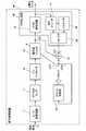
- FIG. 13 illustrates the signal processing device according to Embodiment 3 (that is, the signal processing method according to Embodiment 3 can be implemented). It is a block diagram which shows the structure of (apparatus) 50 roughly. In FIG. 13, the same reference numerals are given to the same or corresponding components as those shown in FIG. 5 (second reference example).
- the signal processing device 50 according to the third embodiment is mounted on the optical disc device 60 shown in FIG. 1 and can constitute a part of the optical disc device 60. As shown in FIG.
- the signal processing device 50 according to the third embodiment includes a data length determination circuit 56, and the selector 57 is switched based on the control signal S ⁇ b> 56 from the data length determination circuit 56. This is different from the signal processing device 20 of the second reference example shown in FIG. In the following description, the signal processing device 50 according to Embodiment 3 will be described focusing on differences from the signal processing device 20 of the second reference example.
- the data length determination circuit 56 determines the data length of the binarized data output from the Viterbi decoding circuit 16, and sends a control signal S56 based on the determination result to the selector 57.
- the data length determination circuit 56 is illustrated as a part of the PRML circuit 55, but the data length determination circuit 56 may be provided outside the PRML circuit 55.
- the selector 57 switches the value of the error signal S33 input to the adaptive filter 14 and the loop filter 192 (shown in FIG. 5) of the clock generation unit 29 based on the control signal S56 received from the data length determination circuit 56.
- the selector 57 based on the received control signal S56, When the signal S32 from the PR decoder 17 is not output to the adder 18 and the data length of the binarized data output from the Viterbi decoding circuit 16 is other than 2T, the target signal S32 output from the PR decoder 17 is The result is output to the adder 18.
- the data length of the binarized data output from the Viterbi decoding circuit 16 is a predetermined data length (data length 2T in the third embodiment). Is an error waveform based on the reproduction waveform.
- the data length of the binarized data output from the Viterbi decoding circuit 16 is other than 2T, an error obtained by subtracting the reproduction signal S31 from the target waveform S32 from the PR decoder 17 It becomes signal S33.
- the value of the signal S33 obtained by subtracting the reproduction signal S31 from the target signal S32 from the PR decoder 17 is switched based on the received control signal S56.
- the amplitude level of the signal output from the PR decoder 47 is changed.
- a signal with a short data length for example, a signal with a data length of 2T and a data length of 3T signal
- the data of the amplitude levels ⁇ 4 and ⁇ 3 are used for the calculation of the phase error.
- the error is The signal calculation includes data of an amplitude level ⁇ 3 that can be taken by a signal having a data length of 2T or 3T.
- the signal processing apparatus 50 according to the third embodiment by adding a data length determination circuit 56, it is possible to know the sampling point relating to a signal having a desired data length. Only the error signal related to the data length signal can be fed back to the loop filter 192 of the clock generator 29. Therefore, in the signal processing device 50 according to the third embodiment, for example, a phase error related to a signal having a data length of 2T can be excluded as the phase error fed back to the loop filter 192 of the clock generation unit 29. In the signal processing device 50 according to the third embodiment, as shown in FIG. 13, by adding the data length determination circuit 56, for example, it is possible to know the sampling point related to a signal having a data length of 2T. Only an error signal related to a signal having a desired data length can be fed back to the loop filter 192 of the clock generation unit 29. A phase error related to a signal having a data length of 2T is excluded from the phase error.
- the modulation method is 1-7 RLL modulation, so the modulation method is not limited to this.
- the 8-16 modulation method used in DVD or CD or the like In the 8-14 modulation method the same effect can be obtained by the same means.
- the phase error relating to the signal having the data length of 2T has been described.
- this is not limited to this depending on the reproduction waveform.
- the signal having the data length of 2T In other words, it is only necessary to exclude a phase error related to a signal having a data length of 3T and a signal having a data length of 4T.
- the point excluding the number of samples related to 2T-4T, that is, the number of samples related to 5T or more is about 152% compared to the case where the slice level is 0 level. Therefore, according to the signal processing device 50 according to the third embodiment, the loop gain is approximately 1.5 times that of the clock generation unit in which the slice level is 0 while reducing the noise.
- ⁇ 3-2 Effects of Embodiment 3
- the signal processing device 50, the signal processing method, and the optical disc device 60 according to Embodiment 3 a stable clock signal can be generated, and as a result, reproduction is possible. There is an effect that the quality of the binarized data as a signal can be improved.
- the signal processing device 50, the signal processing method, and the optical disc device 60 according to the third embodiment it is possible to calculate a phase error with higher accuracy, a waveform deterioration is large, and a reproduced waveform with a high error rate is obtained.
- stable clock signal generation is possible.
- the selector only needs to be equipped with a level selection table and a comparison selection circuit. There is also an effect that the amount of scale increase is extremely small.
- the waveform A stable clock signal can be generated even for a reproduction signal having a large deterioration and a high error rate.
- the effect of the signal processing method can be obtained without increasing the calculation load or the circuit load.
- signal processing device 11 A / D conversion circuit, 12 digital amplifier, 13 pre-equalizer, 14 adaptive filter, 15, 45, 45a, 55 PRML circuit, 16 Viterbi decoding circuit, 17, 47 PR Decoder, 18, 18a adder (calculation unit), 19 PLL circuit, 29 clock generation unit, 37, 57 selector (limitation unit), 48 equalizer, 49 selector, 56 data length determination circuit, 60 optical disc device, 70 optical disc (recording) Medium), 191 phase comparator, 192 loop filter, 193 voltage controlled oscillator, T clock signal 1 cycle length (1 clock cycle).
Abstract
Priority Applications (4)
| Application Number | Priority Date | Filing Date | Title |
|---|---|---|---|
| JP2013511957A JP5766281B2 (ja) | 2011-04-27 | 2012-02-17 | 信号処理装置、信号処理方法、及び光ディスク装置 |
| CN201280020558.5A CN103503071B (zh) | 2011-04-27 | 2012-02-17 | 信号处理装置、信号处理方法及光盘装置 |
| US14/114,059 US8787135B2 (en) | 2011-04-27 | 2012-02-17 | Signal processing device, signal processing method, and optical disc apparatus |
| KR1020137028099A KR101506418B1 (ko) | 2011-04-27 | 2012-02-17 | 신호 처리 장치, 신호 처리 방법, 및 광 디스크 장치 |
Applications Claiming Priority (2)
| Application Number | Priority Date | Filing Date | Title |
|---|---|---|---|
| JP2011099502 | 2011-04-27 | ||
| JP2011-099502 | 2011-04-27 |
Publications (1)
| Publication Number | Publication Date |
|---|---|
| WO2012147392A1 true WO2012147392A1 (fr) | 2012-11-01 |
Family
ID=47071920
Family Applications (1)
| Application Number | Title | Priority Date | Filing Date |
|---|---|---|---|
| PCT/JP2012/053840 WO2012147392A1 (fr) | 2011-04-27 | 2012-02-17 | Dispositif de traitement de signal, procédé de traitement de signal, et dispositif de disque optique |
Country Status (5)
| Country | Link |
|---|---|
| US (1) | US8787135B2 (fr) |
| JP (1) | JP5766281B2 (fr) |
| KR (1) | KR101506418B1 (fr) |
| CN (1) | CN103503071B (fr) |
| WO (1) | WO2012147392A1 (fr) |
Cited By (1)
| Publication number | Priority date | Publication date | Assignee | Title |
|---|---|---|---|---|
| US11070238B2 (en) | 2017-11-27 | 2021-07-20 | Sony Semiconductor Solutions Corporation | Decoding device and decoding method |
Families Citing this family (3)
| Publication number | Priority date | Publication date | Assignee | Title |
|---|---|---|---|---|
| US20180184927A1 (en) * | 2016-12-30 | 2018-07-05 | Eosmem Corporation | Real-time heart rate detection method and real-time heart rate detection system therefor |
| JP7031543B2 (ja) * | 2018-09-21 | 2022-03-08 | 株式会社Jvcケンウッド | 処理装置、処理方法、再生方法、及びプログラム |
| JP2020085679A (ja) * | 2018-11-27 | 2020-06-04 | 日本電産株式会社 | 信号処理装置、モータおよびファンモータ |
Citations (5)
| Publication number | Priority date | Publication date | Assignee | Title |
|---|---|---|---|---|
| JP2001176208A (ja) * | 1999-12-20 | 2001-06-29 | Hitachi Ltd | 位相誤差検出器、同期クロック生成器および記録装置 |
| JP2006120233A (ja) * | 2004-10-21 | 2006-05-11 | Hitachi Ltd | 光ディスク装置 |
| JP2006127559A (ja) * | 2004-10-26 | 2006-05-18 | Hitachi Ltd | 高符号間干渉耐性位相比較器 |
| JP2008146696A (ja) * | 2006-12-06 | 2008-06-26 | Renesas Technology Corp | データ再生装置 |
| JP2009176405A (ja) * | 2007-12-28 | 2009-08-06 | Panasonic Corp | 位相誤差検出装置、波形整形装置及び光ディスク装置 |
Family Cites Families (12)
| Publication number | Priority date | Publication date | Assignee | Title |
|---|---|---|---|---|
| JP3331818B2 (ja) | 1995-06-22 | 2002-10-07 | 松下電器産業株式会社 | ディジタル情報再生装置 |
| US5719843A (en) | 1995-06-22 | 1998-02-17 | Matsushita Electric Industrial Co.Ltd | Method of maximum likelihood decoding and digital information playback apparatus |
| JP3015832B2 (ja) | 1995-06-27 | 2000-03-06 | 富士通株式会社 | データ再生装置 |
| US5991914A (en) | 1996-02-15 | 1999-11-23 | Nec Corporation | Clock recovery using maximum likelihood sequence estimation |
| JP2800758B2 (ja) | 1996-02-15 | 1998-09-21 | 日本電気株式会社 | クロック抽出回路 |
| JP2999759B1 (ja) | 1998-10-13 | 2000-01-17 | 松下電器産業株式会社 | デジタル再生信号処理装置 |
| JP2006252681A (ja) * | 2005-03-11 | 2006-09-21 | Hitachi Ltd | 光ディスク装置及びpll回路 |
| JP2006344294A (ja) * | 2005-06-09 | 2006-12-21 | Hitachi Ltd | 情報再生装置及び再生信号処理回路 |
| CN101052105A (zh) * | 2006-04-03 | 2007-10-10 | 广州市纽帝亚资讯科技有限公司 | 一种视频相关信息表示方法及其播放系统 |
| JP2008159138A (ja) * | 2006-12-22 | 2008-07-10 | Sony Corp | 再生装置および再生方法、信号処理装置および信号処理方法、並びにプログラム |
| US8705673B2 (en) * | 2008-09-05 | 2014-04-22 | Lsi Corporation | Timing phase detection using a matched filter set |
| US8660220B2 (en) * | 2008-09-05 | 2014-02-25 | Lsi Corporation | Reduced frequency data processing using a matched filter set front end |
-
2012
- 2012-02-17 KR KR1020137028099A patent/KR101506418B1/ko active IP Right Grant
- 2012-02-17 CN CN201280020558.5A patent/CN103503071B/zh active Active
- 2012-02-17 JP JP2013511957A patent/JP5766281B2/ja active Active
- 2012-02-17 WO PCT/JP2012/053840 patent/WO2012147392A1/fr active Application Filing
- 2012-02-17 US US14/114,059 patent/US8787135B2/en not_active Expired - Fee Related
Patent Citations (5)
| Publication number | Priority date | Publication date | Assignee | Title |
|---|---|---|---|---|
| JP2001176208A (ja) * | 1999-12-20 | 2001-06-29 | Hitachi Ltd | 位相誤差検出器、同期クロック生成器および記録装置 |
| JP2006120233A (ja) * | 2004-10-21 | 2006-05-11 | Hitachi Ltd | 光ディスク装置 |
| JP2006127559A (ja) * | 2004-10-26 | 2006-05-18 | Hitachi Ltd | 高符号間干渉耐性位相比較器 |
| JP2008146696A (ja) * | 2006-12-06 | 2008-06-26 | Renesas Technology Corp | データ再生装置 |
| JP2009176405A (ja) * | 2007-12-28 | 2009-08-06 | Panasonic Corp | 位相誤差検出装置、波形整形装置及び光ディスク装置 |
Cited By (1)
| Publication number | Priority date | Publication date | Assignee | Title |
|---|---|---|---|---|
| US11070238B2 (en) | 2017-11-27 | 2021-07-20 | Sony Semiconductor Solutions Corporation | Decoding device and decoding method |
Also Published As
| Publication number | Publication date |
|---|---|
| JP5766281B2 (ja) | 2015-08-19 |
| JPWO2012147392A1 (ja) | 2014-07-28 |
| US20140043950A1 (en) | 2014-02-13 |
| CN103503071A (zh) | 2014-01-08 |
| KR20130135978A (ko) | 2013-12-11 |
| US8787135B2 (en) | 2014-07-22 |
| CN103503071B (zh) | 2017-10-27 |
| KR101506418B1 (ko) | 2015-03-26 |
Similar Documents
| Publication | Publication Date | Title |
|---|---|---|
| JP5045448B2 (ja) | 信号処理回路、信号処理方法、再生装置 | |
| JP5042236B2 (ja) | 情報記録媒体評価方法、情報記録媒体、情報記録媒体の製造方法、信号処理方法、アクセス制御装置 | |
| US8913475B2 (en) | Data detecting device, reproducing device, and data detecting method | |
| EP3267440B1 (fr) | Dispositif de détection de données, dispositif de reproduction et procédé de détection de données | |
| JP2011103153A (ja) | 情報検出装置及び光ディスク装置 | |
| US20190325908A1 (en) | Information processing device, information processing method, and program | |
| JP5766281B2 (ja) | 信号処理装置、信号処理方法、及び光ディスク装置 | |
| US7616726B2 (en) | Optical disk apparatus and PLL circuit | |
| US8873358B2 (en) | Skew detection method and optical disc device | |
| US7839735B2 (en) | Phase difference detection apparatus, phase difference detection method, reproduction apparatus and tracking controlling method | |
| US9117485B2 (en) | Signal processing apparatus capable of suppressing non-linear noise component during reading optical recording medium | |
| JP4095487B2 (ja) | 情報再生方法及びそれを用いた情報再生装置 | |
| JP4580380B2 (ja) | 光ディスク装置 | |
| JP4501960B2 (ja) | ビタビ検出器、及び、情報再生装置 | |
| US8339909B2 (en) | Optical disc device | |
| JP5623097B2 (ja) | 情報再生方法及び装置、並びに光ディスク装置 | |
| JP6036798B2 (ja) | データ検出装置、再生装置、データ検出方法 | |
| JP4234042B2 (ja) | 多値情報記録媒体,多値情報波形等化装置,多値情報再生装置 | |
| JP2010152951A (ja) | 光ディスク駆動装置 | |
| JP2004241102A (ja) | 光ディスク装置における収差補正方法 | |
| US20090141605A1 (en) | Optical disc reproducing device and optical disc reproducing method | |
| JP2002197666A (ja) | 記録情報再生装置 | |
| JP2011141935A (ja) | 波形等化回路および波形等化方法 | |
| JP2011216170A (ja) | 情報再生装置および情報再生方法 |
Legal Events
| Date | Code | Title | Description |
|---|---|---|---|
| 121 | Ep: the epo has been informed by wipo that ep was designated in this application |
Ref document number: 12777122 Country of ref document: EP Kind code of ref document: A1 |
|
| ENP | Entry into the national phase |
Ref document number: 2013511957 Country of ref document: JP Kind code of ref document: A |
|
| ENP | Entry into the national phase |
Ref document number: 20137028099 Country of ref document: KR Kind code of ref document: A |
|
| WWE | Wipo information: entry into national phase |
Ref document number: 14114059 Country of ref document: US |
|
| NENP | Non-entry into the national phase |
Ref country code: DE |
|
| 122 | Ep: pct application non-entry in european phase |
Ref document number: 12777122 Country of ref document: EP Kind code of ref document: A1 |