WO2012143992A1 - シャシ構造 - Google Patents
シャシ構造 Download PDFInfo
- Publication number
- WO2012143992A1 WO2012143992A1 PCT/JP2011/059528 JP2011059528W WO2012143992A1 WO 2012143992 A1 WO2012143992 A1 WO 2012143992A1 JP 2011059528 W JP2011059528 W JP 2011059528W WO 2012143992 A1 WO2012143992 A1 WO 2012143992A1
- Authority
- WO
- WIPO (PCT)
- Prior art keywords
- wheel
- chassis structure
- vehicle
- pair
- spine
- Prior art date
- Legal status (The legal status is an assumption and is not a legal conclusion. Google has not performed a legal analysis and makes no representation as to the accuracy of the status listed.)
- Ceased
Links
Images



Classifications
-
- B—PERFORMING OPERATIONS; TRANSPORTING
- B62—LAND VEHICLES FOR TRAVELLING OTHERWISE THAN ON RAILS
- B62D—MOTOR VEHICLES; TRAILERS
- B62D61/00—Motor vehicles or trailers, characterised by the arrangement or number of wheels, not otherwise provided for, e.g. four wheels in diamond pattern
- B62D61/02—Motor vehicles or trailers, characterised by the arrangement or number of wheels, not otherwise provided for, e.g. four wheels in diamond pattern with two road wheels in tandem on the longitudinal centre line of the vehicle
- B62D61/04—Motor vehicles or trailers, characterised by the arrangement or number of wheels, not otherwise provided for, e.g. four wheels in diamond pattern with two road wheels in tandem on the longitudinal centre line of the vehicle with two other wheels which are coaxial
-
- B—PERFORMING OPERATIONS; TRANSPORTING
- B62—LAND VEHICLES FOR TRAVELLING OTHERWISE THAN ON RAILS
- B62D—MOTOR VEHICLES; TRAILERS
- B62D21/00—Understructures, i.e. chassis frame on which a vehicle body may be mounted
- B62D21/02—Understructures, i.e. chassis frame on which a vehicle body may be mounted comprising longitudinally or transversely arranged frame members
- B62D21/04—Understructures, i.e. chassis frame on which a vehicle body may be mounted comprising longitudinally or transversely arranged frame members single longitudinal type
-
- B—PERFORMING OPERATIONS; TRANSPORTING
- B62—LAND VEHICLES FOR TRAVELLING OTHERWISE THAN ON RAILS
- B62D—MOTOR VEHICLES; TRAILERS
- B62D21/00—Understructures, i.e. chassis frame on which a vehicle body may be mounted
- B62D21/06—Understructures, i.e. chassis frame on which a vehicle body may be mounted of X-shaped or fork-shaped construction, i.e. having members which form an X or fork as the frame is seen in plan view
-
- B—PERFORMING OPERATIONS; TRANSPORTING
- B62—LAND VEHICLES FOR TRAVELLING OTHERWISE THAN ON RAILS
- B62D—MOTOR VEHICLES; TRAILERS
- B62D21/00—Understructures, i.e. chassis frame on which a vehicle body may be mounted
- B62D21/15—Understructures, i.e. chassis frame on which a vehicle body may be mounted having impact absorbing means, e.g. a frame designed to permanently or temporarily change shape or dimension upon impact with another body
- B62D21/152—Front or rear frames
Definitions
- the present invention relates to a vehicle having a single front wheel disposed in the front portion of the vehicle and left and right wheels disposed on the left and right of the vehicle behind the front wheel, and particularly to such a vehicle.
- a vehicle having a single front wheel disposed in the front portion of the vehicle and left and right wheels disposed on the left and right of the vehicle behind the front wheel, and particularly to such a vehicle.
- Patent Document 1 Conventionally, a vehicle having a single front wheel and a left wheel and a right wheel provided behind the same as described in Patent Document 1 below has been studied.
- a vehicle as described in Patent Document 2 below that is, a vehicle having a single rear wheel provided behind the left wheel and the right wheel in addition to the three wheels has been studied.
- the vehicle as described above (hereinafter sometimes referred to as “wheel specially arranged vehicle”) is a normal vehicle having two left and right front wheels and two right and left rear wheels (hereinafter sometimes referred to as “wheel four corner arranged vehicle”). Therefore, the structure of the chassis used for the wheel specially arranged vehicle is naturally different from the structure of the chassis used for the wheel arranged at the four corners.
- the chassis structure for the wheel specially arranged vehicle still has room for sufficient improvement, and it is possible to improve the practicality of the wheel specially arranged vehicle by applying some kind of improvement.
- This invention is made
- the chassis structure for a vehicle with specially arranged wheels includes a front wheel, a right wheel, and a left wheel surrounded by a front wheel, a right wheel, and a front wheel, respectively. And a pair of anterior scapulae arranged so as to sandwich the front wheel, with one tip located on the right side of the front wheel and the other tip located on the left side of the front wheel. Composed.
- the vehicle in which the chassis structure of the present invention is used can suppress the deformation of the passenger compartment space by the forward oblique bone even when the vehicle collides with another vehicle, an obstacle, or the like in the right front or left front. Yes, it is possible to ensure the safety of passengers. Since it has such an advantage, it is possible to improve the practicality of the wheel specially arranged vehicle by using the chassis structure of the present invention for the wheel specially arranged vehicle.
- the item (1) corresponds to the item 1, and the invention specific matter of the item (2) is added to the item 1, the item 1 or the item 2.
- the invention-specific matters of (6) are added to claim 3, the invention-specific matters of (7) are added to claim 3 in claim 4, and claims 4-8 are added.
- the invention-specific matters are added to claim 5, the invention-specific matters of (9) are added to any one of claims 3 to 5, and claims 6 to 1 are added.
- the invention specific matter of (3) added to any one of 6 is added to claim 7, and the invention specific matter of (4) is added to claim 7 in claim 8.
- a chassis structure for holding the right wheel and the left wheel One front end extends from the center of the chassis structure surrounded by the front wheel, the right wheel, and the left wheel, between the front wheel and the right wheel, and between the front wheel and the left wheel, respectively.
- a chassis structure that includes a pair of front oblique bones that are positioned on the right side of the front wheel and the other tip is positioned on the left side of the front wheel and are disposed so as to sandwich the front wheel.
- a vehicle in which the chassis structure described in this section is used is the above-described wheel special arrangement vehicle, and the vehicle may be a three-wheeled vehicle having only the front wheel, the left wheel, and the right wheel, and further, the left wheel and the right wheel. It may be a vehicle having a single rear wheel disposed behind the vehicle (hereinafter sometimes referred to as a “wheel diamond-shaped vehicle”).
- the chassis structure described in this section includes a chassis frame that serves as a vehicle skeleton.
- the chassis structure described in this section is not limited to the chassis structure of a vehicle in which the chassis frame and the body are separately configured, that is, a so-called separate frame type vehicle, but the chassis frame is formed integrally with the body.
- a chassis structure of a so-called frameless body type (monocoque body type) vehicle is the above-described wheel special arrangement vehicle, and the vehicle may be a three-wheeled vehicle having only the front wheel, the left wheel, and the right wheel, and further, the left wheel and the right wheel.
- the four-corner-equipped vehicle has wheels arranged at the left and right corners of the front part, so that these front wheels are held.
- the chassis structure or the like suppresses the deformation of the passenger compartment space and ensures the safety of the passenger.
- the vehicle with the specially arranged wheels has a passenger safety in the case of a so-called offset collision when the vehicle collides in the left front or right front of the vehicle. Ensuring is a problem. Furthermore, in a wheel specially arranged vehicle, it has been studied to round the right front and left front of the vehicle body from the above wheel arrangement. In a wheel specially arranged vehicle, when the vehicle body has such a shape, a stroke amount for absorbing an impact at the time of an offset collision is short, and ensuring safety for passengers is particularly problematic.
- the chassis structure described in this section is configured to include a bone extending diagonally right forward from the center of itself and a bone extending diagonally forward left. From such a configuration, according to the chassis structure described in this section, it is possible to suppress the deformation of the passenger compartment space by the front oblique bone when the vehicle collides with an offset. In other words, the wheel specially arranged vehicle using the chassis structure described in this section can ensure the safety of the occupant at the time of an offset collision, and is highly practical.
- a pair of anterior oblique bones] described in this section may be any one that is arranged as described above and forms a part of the skeleton of the chassis structure. That is, each of the pair of anterior oblique bones does not have to be independent as one member or component, and may be formed integrally. In addition, each of the pair of anterior oblique bones may be configured integrally with other bones included in the chassis structure. Further, when the chassis structure is used in the above frameless body type vehicle, each of the pair of front scapular bones may be integrally formed with the body.
- the chassis structure has various bones in addition to a pair of anterior oblique bones.
- these various bones do not have to be independent as one member or component, like the pair of anterior antrum, and may be configured integrally with other bones. It may be configured integrally with the body.
- Each of the pair of anterior scaphoids is The chassis structure according to item (1), in which each of the tips is arranged so as to be positioned in front of a passenger compartment formed in a vehicle in which the chassis structure is used.
- the passenger compartment space is not deformed unless the forward oblique bone is deformed to some extent. Therefore, the aspect of this section is suitable for ensuring the safety of the passenger. .
- a vehicle using the chassis structure is configured such that seats are provided on each of the right side and the left side of the center part of the chassis structure, Each will be arrange
- chassis structure according to (1) or (2), wherein the chassis structure has a front central bone disposed so as to extend from the central portion toward the upper side of the front wheel.
- the number of bones extending from the central portion toward the front is increased, so that the strength in front of the vehicle can be improved and the safety of the occupant against a collision in front of the vehicle can be improved. is there.
- the chassis structure is (3) A connecting bone that is passed to the distal end portion of the front central bone and the distal end portions of each of the pair of anterior antrum and connects the anterior central bone and each of the pair of anterior antrum.
- the front end portion of the front wheel central bone and the front end of each of the front oblique bones are connected by the connecting bone, so that the strength in front of the vehicle can be further improved.
- the bending strength of each of the front wheel central bone and the front oblique bone is increased, the deformation of the vehicle is suppressed even in a collision in a direction intersecting with the extending direction of the front oblique bone, and the safety of the occupant is ensured. It is possible.
- the front wheel is a steered wheel, The chassis structure according to (3) or (4), wherein the steered shaft of the front wheel is configured to be held at the tip of the front central bone.
- the chassis structure described in this section is configured such that the distal end portion of the front wheel central bone is positioned above the front wheel, and the front wheel central bone holds the steered shaft of the front wheel that is the steered wheel at the distal end portion. It is configured as follows.
- the chassis structure is configured to include a spine disposed in a state extending in the front-rear direction at the central portion, Each of the pair of anterior scapula is fixed to the front end of the spine at the rear end of each of them, and is arranged to extend from the front end of the spine (1) to (5)
- the chassis structure according to any one of the above.
- the “spine” is the center of the chassis skeleton.
- the chassis structure described in this section is arranged such that the center of the chassis skeleton extends in the vehicle width direction center of the vehicle in the front-rear direction. According to the aspect of this section, it is possible to secure a space for installing the left and right wheel suspension devices, and to increase the degree of freedom in designing the suspension devices. For example, even in a vehicle having a small vehicle width, a relatively wide space can be secured in order to install the left and right wheel suspension devices. It is particularly effective.
- the weight of the spine is relatively large, it is disposed at a position relatively close to the center of gravity of the vehicle. Can be reduced. Therefore, according to the aspect of this section, it is possible to improve the stability and movement performance of the vehicle during travel.
- the spine is disposed between the two seats.
- the height of the spine can be increased without increasing the height of the floor. In other words, it is not necessary to raise the floor even if the height of the spine is increased.
- the chassis structure includes a floorboard, The chassis structure according to item (6), wherein the spine is disposed in a state of protruding upward from the floor board.
- the upper surface of the spine is located above the floor. That is, according to the aspect of this section, it is possible to lower the position of the center of gravity of the vehicle body as compared with the case where the floor is provided on the spine. Moreover, if a seat is provided on each of the left and right sides of the spine, the height of the seat is reduced, and a vehicle excellent in getting on and off is realized.
- each of the pair of anterior scaphoids and the spine are disposed so as to be positioned in one plane.
- the height of the pair of anterior obliques is the same as that of the spine. Therefore, in the event of a collision in front of the vehicle, it is possible to support each of the pair of front scapulas from the rear. That is, if the chassis structure described in this section is used, the vehicle strength in the front-rear direction can be further increased, and the safety of the passenger can be further improved.
- the aspect of this section is combined with the aspect in which the above-described spine protrudes above the floor, even if the vehicle using the chassis structure is a relatively small vehicle, the height of the floor It is possible to increase the height of the chassis skeleton without increasing the height.
- the small vehicle using the chassis structure having such a configuration can match the height of the chassis skeleton with the height of a bumper or the like of a vehicle of a general size, and has excellent occupant safety. Become a vehicle.
- the vehicle in which the chassis structure is used further includes a single rear wheel arranged behind the left wheel and the right wheel, and any one of the items (1) to (9) The chassis structure described in 1.
- the chassis structure described in this section is used for the wheel rhombus arrangement vehicle described above.
- the chassis structure is Respectively, extending from the central portion between the rear wheel and the right wheel and between the rear wheel and the left wheel, with one tip positioned on the right side of the rear wheel and the other tip positioned on the rear wheel.
- the same oblique bone as the forward oblique bone is disposed on the rear side of the vehicle as well as the front side of the vehicle.
- the chassis structure described in this section is arranged with a rear wheel central bone extending from the central portion toward the upper side of the rear wheel corresponding to the rear wheel, like the front wheel central bone provided in the front portion of the vehicle. It is also possible to set up. Furthermore, when the chassis structure has a rear wheel central bone, it is possible to add the features described in the aspect related to the front wheel central bone to the rear wheel central bone. Specifically, it is possible to connect the distal end portions of the pair of posterior oblique bones and the distal end portion of the rear wheel central bone. Further, the rear wheel can be configured to be held at the distal end portion of the rear wheel central bone.
- the chassis structure is configured to include a spine disposed in the central portion in a state of extending in the front-rear direction, Each of the pair of anterior vertebrae is fixed to the front end portion of the spine at their respective rear ends, and is arranged to extend from the front end portion of the spine, and the pair of posterior vertebrae
- the chassis skeleton is mainly composed of the spine and the oblique bones extending from the spine to the left front, right front, left rear, and right rear. It is possible to add the aspect regarding the spine mentioned above to the aspect of this term.
- the aspect of this section can be configured such that the spine protrudes upward from the floor plate, and the aspect of this section includes a pair of anterior scapula and a pair of posterior vertebrae. It is possible to adopt a configuration in which the oblique bone is disposed so as to lie in one plane with the spine.
- the spine can be formed in a rectangular frame shape.
- the chassis structure is disposed in a state where the spine protrudes upward from the floor plate, and the pair of anterior vertebrae and the pair of posterior posterior bones are disposed in a plane with the spine.
- it is divided into a portion surrounded by the spine, the right anterior oblique and the right posterior oblique, and a portion surrounded by the spine, the left anterior oblique and the left posterior oblique. It can be configured to provide a seat.
- the chassis skeleton is generally formed in an X shape.
- the aspect described in this section is a chassis structure having a relatively simple configuration because the pair of anterior scaphobia and the pair of posterior posterior vertebrae are connected without any other member or component.
- the chassis structure described in this section can be configured such that a pair of anterior and posterior vertebrae protrude upward from the floorboard. With such a configuration, the position of the center of gravity of the vehicle body can be lowered.
- seats are provided between the right front posterior bone and the right posterior vertebra, and between the left front vertebra and the left posterior vertebra, the height of the seat will be reduced, making it easier to get on and off. An excellent vehicle is realized.
- a vehicle in which the chassis structure is used The chassis structure according to any one of (1) to (13), wherein a seat is provided on each of a right side and a left side of the central portion.
- the aspect described in this section is limited in the position of the seat provided in the vehicle. Since the chassis structure has a part of the skeleton (center part) at a location surrounded by wheels, the chassis structure configured so that the center part projects upward from the floor is desirable in the aspect of this section. .
- FIG. 1 is a schematic side view of a vehicle using a chassis structure that is a first embodiment of the claimable invention
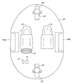
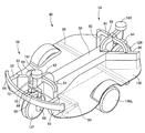
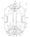
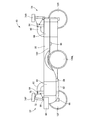
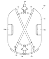
- FIG. It is a schematic plan view of the vehicle shown in FIG. It is a perspective view which shows the chassis of the vehicle shown in FIG. It is a top view which shows the chassis of the vehicle shown in FIG. It is a side view which shows the chassis of the vehicle shown in FIG. It is a front view which shows the chassis of the vehicle shown in FIG. It is a top view which shows the chassis structure which is a modification of 1st Example. It is a top view which shows the chassis structure which is 2nd Example of claimable invention.
- FIG. 1 shows a vehicle using a chassis structure according to a first embodiment of the claimable invention.
- This vehicle is a small vehicle expected as a next-generation commuter, and is a vehicle having wheels arranged in a diamond shape. That is, this vehicle has a front wheel 12F disposed at its front part, a left wheel 12M L and a right wheel 12M R disposed at its left part and right part behind the front wheel 12F, and these left wheel 12M L. , and a wheel 12R after being placed in the rear of the right wheel 12M R.
- FIG. 2 showing a plan view of the vehicle, the front wheel 12F and the rear wheel 12R are arranged at the center in the vehicle width direction.
- the rear wheels 12R are collectively referred to as the wheel 12
- the left wheel 14M L when not required to distinguish the right wheel 14M R is collectively referred to as the wheel 14 I will do it.
- F, M L , M R , and R are attached to the one corresponding to each of the rings.
- the front wheels 12F, the rear wheels 12R are the steered wheels, the left wheel 14M L, the right wheel 14M R is not the steered wheels.
- the left wheel 14M L and the right wheel 14M R are driving wheels (wheels that are rotationally driven to drive the vehicle)
- the front wheels 12F and the rear wheels 12R are not driving wheels.
- the front wheel 12F, the left wheel 14M L , the right wheel 14M R , and the rear wheel 12R that is, all the wheels are brake wheels (wheels whose rotation is braked to brake the vehicle).
- the vehicle is provided with a pair of seats 20, 22, with the right seat 20 of the vehicle serving as a driver seat and the left seat 22 serving as a passenger seat.
- three operation members are provided corresponding to the seat 20 that is a driver's seat as operation members for the driver to operate the vehicle.
- a steering wheel 30 that is a steering operation member for causing the vehicle to perform a turning operation
- the other is an accelerator pedal 32 that is an accelerator operation member for accelerating the vehicle
- the other is an operation of the vehicle.
- It is the brake pedal 34 which is a brake operation member for decelerating.
- the vehicle has a structure in which a body 42 is mounted on a chassis frame 40 for holding the four wheels 12 and 14.
- the chassis of the vehicle including the chassis frame 40 will be described in detail with reference to FIGS. 3 is a perspective view of the chassis, FIG. 4 is a plan view of the chassis, FIG. 5 is a side view of the chassis, and FIG. 6 is a front view of the chassis.
- the chassis frame 40 is a skeleton of the vehicle and is the main body of the chassis structure of the present embodiment.
- the chassis frame 40 includes a center frame 50 as a backbone disposed in a state extending in the longitudinal direction of the vehicle at the center in the vehicle width direction, a front frame 52 disposed in front of the center frame 50, and a center frame. 50 and a rear frame 54 disposed behind the vehicle 50.
- the front frame 52 are fixed to the front end of the center frame 50, between the front wheel 12F and the right wheel 14M R, include a forward oblique bone 60 of a pair extending toward between the front wheel 12F and the left wheel 14M L Consists of.
- Each of the pair of front oblique bones 60 is arranged so that the tip of the right one is located on the right side of the front wheel 12F and the tip of the left one is located on the left side of the front wheel 12F, and sandwiches the front wheel 12F. Yes.
- the front frame 52 includes a front wheel central bone 62 that extends from the front end of the center frame 50 toward the upper side of the front wheel 12F.
- the front wheel central bone 62 has a distal end portion connected to each distal end portion of the pair of anterior oblique bones 60 by a pair of connecting members 64. More specifically, the pair of connecting members 64 generally extend in the vehicle width direction and extend between the front end portion of the front wheel central bone 62 and the front end portions of each of the pair of front oblique bones 60.
- the central bone 62 and each of the pair of anterior oblique bones 60 are connected.
- the front wheel 12F is held at the tip of the front wheel central bone 62.
- the front wheel 12 ⁇ / b> F is sandwiched from the left and right by a pair of hydraulic shock absorbers 66 and is rotatably held at the lower ends of each of the pair of shock absorbers 66.
- the upper ends of each of the pair of shock absorbers 66 are fixed to a support plate 66 extending in the vehicle width direction, and the support plate 68 connects the upper ends of the pair of shock absorbers 66.
- a turning shaft 70 is fixedly attached to the support plate 68, and the turning shaft 70 is rotatably held by a bearing portion 72 provided at the front end of the front wheel central bone 62.
- the steering device 74F includes an electromagnetic motor, and is configured to steer the front wheels 12F at an arbitrary turning angle by controlling the operation of the electromagnetic motor. Further, the front wheel 12F is prevented from being steered by 90 ° or more on both the left and right sides by a stopper (not shown).
- the front frame 52 further includes a front cross member 80 that extends in the vehicle width direction, a pair of front side members 82 that extend in the front-rear direction, and a bumper reinforcement 84 that is positioned behind the bumper of the vehicle. Composed.
- the front cross member 80 is fixed to the front end portion of the center frame 50 so as to penetrate the center frame 50 and extend in the vehicle width direction.
- One of the pair of front side members 82 has a rear end fixed to the right end of the front cross member 80, and is fixed to the front end of the right front oblique bone 60 at the front end.
- the other end of the pair of front side members 82 has a rear end fixed to the left end of the front cross member 80 and a front end fixed to the front end of the left front oblique bone 60.
- a bumper reinforcement 84 formed in a generally arc shape in plan view is fixed to the front end of each of the pair of front side members 82.
- the rear frame 54 is configured in the same manner as a part of the front frame 52 described above. Specifically, the rear frame 54 is configured to include a pair of posterior vertebra 90 and a rear wheel central bone 92 similar to the pair of anterior sympathy 60 and front wheel central bone 62 constituting the front frame 52.
- the A pair of rear oblique bone 90, respectively, are fixed to the rear end of the center frame 50, between the rear wheels 12R and right wheel 14M R, so as to extend between the rear wheel 12R and left wheel 14M L Arranged.
- each of the pair of rear oblique bones 90 the tip of the right one is located on the right side of the rear wheel 12R, and the tip of the left one is located on the left side of the rear wheel 12R so as to sandwich the rear wheel 12R. It is arranged.
- the rear wheel central bone 92 is disposed so as to extend from the rear end of the center frame 50 toward the upper side of the rear wheel 12R.
- the rear ring central bone 92 is connected at its distal end to each distal end of the pair of posterior obliques 90 by a pair of connecting members 94.
- the rear wheel 12R is held at the tip of the rear wheel central bone 92 by a configuration similar to the configuration in which the front wheel 12F is held by the front wheel central bone 62, and is provided corresponding to the rear wheel 12R.
- the vehicle is steered by the steering device 74R.
- the rear frame 54 also includes a rear cross member 96 extending in the vehicle width direction.
- the rear cross member 96 is fixed to the rear end portion of the center frame 50 so as to penetrate the center frame 50 and extend in the vehicle width direction.
- the chassis frame 40 is of a so-called platform type, and includes a floor pan 100 that is a floor plate that partitions the lower surface of the passenger compartment in addition to the center frame 50, the front frame 52, and the rear frame 54 described above. Yes.
- the floor pan 100 is fixed to the upper surfaces of the front cross member 80 and the rear cross member 96 on the right side and the left side of the center frame 50.
- the center frame 50, the pair of anterior vertebrae 60, and the pair of posterior vertebrae 90 are formed to have the same length in the vertical direction, and are arranged at the same height. That is, as can be seen from FIG. 3 and FIG. 5, the center frame 50, the pair of anterior vertebrae 60, and the pair of posterior vertebrae 90 protrude from the floor pan 100 upward.
- sheets 20 and 22 are disposed on the right side and the left side of the center frame 50, respectively.
- the front end of the vehicle compartment space is partitioned in front of the accelerator pedal 32 and the brake pedal 34, and each of the pair of front scapulas 60 is forward of the vehicle compartment space.
- Each of the pair of anterior scaphobia 60 is disposed such that the tip is located.
- a vehicle in which the chassis structure configured as described above is used is a vehicle with wheels arranged in a rhombus, and is obliquely forward and obliquely rearward of a general vehicle in which wheels are disposed at four corners of the vehicle. Collisions, so-called offset collisions, are a problem. Further, as shown in FIG. 2, the vehicle in which the chassis structure is used has a rounded shape at the four corners of the vehicle, and the stroke amount for absorbing the shock at the time of the offset collision is short. Especially problematic.
- a pair of front oblique bones 60 are disposed between the front wheel 12F and the left and right wheels 14, and the rear wheel 12R and the left and right wheels 14 are disposed.
- a pair of posterior vertebrae 90 is disposed between each of the posterior vertebrae 90, so that even in the case of an offset collision, the pair of anterior vertebrae 60, The deformation of the vehicle can be suppressed, and the safety of the passenger can be ensured.
- the chassis structure is configured such that the center frame 50 supports each of the pair of anterior scaphobia 60 from the rear during a frontal collision and supports each of the pair of the posterior vertebrae 90 from the front at the time of a rearward collision. Therefore, the strength of the vehicle in the front-rear direction is high, and occupant safety is improved. Further, since the center frame 50 is disposed at the center in the vehicle width direction, a wide space for installing the suspension device for the left and right wheels 14 is secured in the present vehicle. The degree of freedom in device design is high.
- center frame 50 is relatively large and has a relatively large weight
- the center frame 50 is disposed near the center of gravity of the vehicle body, the moment of inertia when the vehicle is yawed or rolled is reduced. Yes.
- a vehicle using this chassis structure has excellent stability and motion performance when traveling.
- the center frame 50, the pair of anterior oblique bones 60, and the pair of posterior oblique bones 90 are disposed so as to protrude upward from the floor pan 100.
- the floor pan 100 is provided at a position lower than the upper surfaces of the center frame 50, the pair of anterior vertebra 60, and the pair of the posterior vertebra 90.
- the center of gravity of the vehicle body of the present vehicle is lower than when the floor pan 100 is provided on the upper surface of the center frame 50, the pair of front scapula 60, and the pair of posterior tilt bones 90. ing.
- the seats 20 and 22 are arranged on the floor pan 100 that is lowered, the vehicle is excellent in getting on and off. Further, as described above, this vehicle is a small vehicle.
- the center frame 50, the pair of front scapula 60, and the pair of posterior vertebra 90 are low in height from the ground. Since it is not, it is located close to the bumper height of an average size vehicle. Therefore, when the vehicle collides with another vehicle, the center frame 50, the pair of front squins 60, and the pair of rear squins 90 can surely suppress deformation of the vehicle. Yes.
- the center frame 50 that is the spine is a simple prismatic member.
- the center frame 120 is viewed in plan view as shown in FIG. Are formed in a rectangular frame shape.
- a battery, an auxiliary machine, etc. are arrange
- FIG. That is, according to the chassis structure of the present modification, it is possible to reliably protect the one disposed inside the center frame 120 in the event of a vehicle collision.
- these various devices are disposed near the center of gravity of the vehicle body, the moment of inertia when the vehicle is yawed or rolled is further reduced.
- the chassis frame 40 that is a skeleton of the vehicle and the body 42 are used in vehicles having different configurations, that is, a so-called separate frame type vehicle.
- a monocoque body type vehicle such as a so-called frameless body type vehicle.
- FIG. 8 is a plan view of a vehicle chassis using the chassis structure of the second embodiment.
- the same components as those of the chassis structure of the first embodiment are indicated by the same reference numerals, and the description thereof is omitted or simplified. Assumed to be performed.
- the chassis frame 150 that is the main body of the chassis structure of this embodiment includes four inclined bones 152, 154, 156, and 158.
- Oblique bone 152 extends toward between the center of the vehicle between the front wheel 12F and the right wheel 14M R
- oblique bone 154 extends toward between the center of the vehicle between the front wheel 12F and the left wheel 14M L
- oblique bone 156 extends toward between the center of the vehicle between the rear wheel 12R and the right wheel 14M R
- oblique bone 158 extends toward between the rear wheel 12R and left wheel 14M L from the center of the vehicle.
- These four oblique bones 152, 154, 156 and 158 are fixed at the center of the vehicle.
- the skeleton of the chassis structure of the present embodiment is formed in an X shape by the four oblique bones 152, 154, 156, and 158, and has a structure without a spine like the chassis structure of the first embodiment. It has become.
- the two oblique bones 152 and 154 extending toward the front of the vehicle function as a pair of front oblique bones, and the two inclined bones 156 and 158 extending toward the rear of the vehicle are paired rearward. Acts as the oblique bone.
- the vehicle using the chassis structure of the present embodiment like the vehicle using the chassis structure of the first embodiment, has a pair of front oblique bones 152, 154 even in the case of an offset collision.
- the pair of rear oblique bones 156 and 158 can suppress the deformation of the vehicle and can ensure the safety of the occupant.
- the chassis structure of the present embodiment is directly compared with the chassis structure of the first embodiment because the rear ends of each of the pair of anterior oblique bones and the respective front ends of the pair of posterior oblique bones are directly fixed.
- the configuration is relatively simple.
- 12F front (steerable wheels) 14M L: left wheel 14M R: right wheel 12R: rear wheel (steered wheels) 20, 22: sheet (1 pair seat) 40: chassis frame 42: Body 50: center frame (spine) 52 : Front frame 54: Rear frame 60: One pair of front scaphoid 62: Front wheel central bone 64: Connection member (connection bone) 70: Steering shaft 74: Steering device 90: One pair of rear scaphoid 92: Rear wheel Central bone 94: connecting member (connecting bone) 100: floor pan (floor plate) 120: center frame (spine) 150: chassis frame 152, 154: oblique bone (a pair of anterior oblique bones) 156, 158: inclined bone (1 Twin posterior obliques)
Landscapes
- Engineering & Computer Science (AREA)
- Chemical & Material Sciences (AREA)
- Combustion & Propulsion (AREA)
- Transportation (AREA)
- Mechanical Engineering (AREA)
- Body Structure For Vehicles (AREA)
- Automatic Cycles, And Cycles In General (AREA)
Abstract
Description
前記前輪、前記右輪、および前記左輪に囲まれた当該シャシ構造の中央部から、それぞれ、前記前輪と前記右輪との間,前記前輪と前記左輪との間に向かって延び、一方の先端が前記前輪の右側に位置するとともに他方の先端が前記前輪の左側に位置し、前記前輪を挟むように配設された1対の前方斜骨を含んで構成されたシャシ構造。
それら各々の先端が、当該シャシ構造が用いられる車両に形成される車室空間より前方に位置するように配設された(1)項に記載のシャシ構造。
前記前方中央骨の先端部と前記1対の前方斜骨の各々の先端部とに渡され、それら前方中央骨と1対の前方斜骨の各々とを連結する連結骨を有する(3)項に記載のシャシ構造。
その前輪の転舵軸が、前記前方中央骨の先端部に保持されるように構成された(3)項または(4)項に記載のシャシ構造。
前記1対の前方斜骨の各々が、それら各々の後端部において前記背骨の前端部に固定され、その背骨の前端部から延び出すように配設された(1)項ないし(5)項のいずれか1つに記載のシャシ構造。
前記背骨が、前記床板から上方に突出した状態で配設された(6)項に記載のシャシ構造。
それぞれ、前記中央部から前記後輪と前記右輪との間,前記後輪と前記左輪との間に向かって延び、一方の先端が前記後輪の右側に位置するとともに他方の先端が前記後輪の左側に位置し、前記後輪を挟むように配設された1対の後方斜骨を含んで構成された(10)項に記載のシャシ構造。
前記1対の前方斜骨の各々が、それら各々の後端部において前記背骨の前端部に固定され、その背骨の前端部から延び出すように配設されるとともに、前記1対の後方斜骨の各々が、それら各々の前端部において前記背骨の後端部に固定され、その背骨の後端部から延び出すように配設された(11)項に記載のシャシ構造。
前記中央部の右側と左側との各々に、座席が設けられるものである(1)項ないし(13)項のいずれか1つに記載のシャシ構造。
図1に、請求可能発明の第1実施例であるシャシ構造が用いられた車両を示す。本車両は、次世代コミュータとして期待されている小型車両であり、車輪を菱形状に配置した車両である。つまり、本車両は、自身の前方部に配置された前輪12Fと、その前輪12Fの後方において自身の左部,右部にそれぞれ配置された左輪12ML,右輪12MRと、それら左輪12ML,右輪12MRの後方に配置された後輪12Rとを有している。当該車両の平面視を示す図2から解るように、前輪12F,後輪12Rは、車幅方向における中央に配置されている。なお、以下の説明において、前輪12F,後輪12Rの区別を要しない場合には、車輪12と総称し、左輪14ML,右輪14MRの区別を要しない場合には、車輪14と総称することとする。前輪12F,後輪12R,左輪14ML,右輪14MRに関係する構成要素,パラメータ等についても、車輪12,14と同様に、車輪位置を示す添え字として、前輪,左輪,右輪,後輪の各々に対応するものにF,ML,MR,Rを付す場合がある。
以上のような構成とされた本シャシ構造が用いられる車両は、車輪菱形配置車両であり、車両の四隅に車輪が配置された一般的な車両に比較して、車両の斜め前方および斜め後方における衝突、いわゆるオフセット衝突が問題となる。また、本シャシ構造が用いられる車両は、図2に示したように、車両の四隅が丸みを帯びた形状とされ、オフセット衝突時における衝撃吸収するためのストローク量が短いため、そのオフセット衝突が、特に問題となる。上述のような構成とされた本シャシ構造が用いられる車両は、前輪12Fと左右輪14の各々との間には、1対の前方斜骨60が配設され、後輪12Rと左右輪14の各々との間には、1対の後方斜骨90が配設されているため、オフセット衝突した場合であっても、それら1対の前方斜骨60,1対の後方斜骨90によって、車両の変形を抑制することが可能であり、乗員の安全を確保することが可能となっている。
上記実施例のシャシ構造においては、背骨であるセンタフレーム50は、単なる角柱状の部材であったが、本変形例のシャシ構造においては、センタフレーム120が、図7に示すように、平面視において四角形の枠状に形成されている。そして、本車両においては、バッテリや補機等が、そのセンタフレーム120の内側に配設されている。つまり、本変形例のシャシ構造によれば、そのセンタフレーム120の内側に配設されたものを、車両の衝突時に確実に保護することが可能である。また、それら種々の機器が車体の重心位置近くに配設されるため、車両のヨーやロールの際の慣性モーメントがより小さくなっている。
Claims (12)
- 自身の前方部の車幅方向における中央に配置された単一の前輪とその前輪より後方において自身の左右にそれぞれ配置された左輪および右輪とを有する車両に用いられ、それら前輪、右輪、および左輪を保持するためのシャシ構造であって、
前記前輪、前記右輪、および前記左輪に囲まれた当該シャシ構造の中央部から、それぞれ、前記前輪と前記右輪との間,前記前輪と前記左輪との間に向かって延び、一方の先端が前記前輪の右側に位置するとともに他方の先端が前記前輪の左側に位置し、前記前輪を挟むように配設された1対の前方斜骨を含んで構成されたシャシ構造。 - 前記1対の前方斜骨の各々が、
それら各々の先端が、当該シャシ構造が用いられる車両に形成される車室空間より前方に位置するように配設された請求項1に記載のシャシ構造。 - 当該シャシ構造が、前記中央部に前後方向に延びる状態で配設された背骨を含んで構成され、
前記1対の前方斜骨の各々が、それら各々の後端部において前記背骨の前端部に固定され、その背骨の前端部から延び出すように配設された請求項1または請求項2に記載のシャシ構造。 - 当該シャシ構造が、床板を含んで構成され、
前記背骨が、前記床板から上方に突出した状態で配設された請求項3に記載のシャシ構造。 - 前記1対の前方斜骨の各々と前記背骨とが、一平面内に位置するように配設された請求項4に記載のシャシ構造。
- 前記背骨が、上方から見た場合において四角形の枠状に形成されたものである請求項3ないし請求項5のいずれか1つに記載のシャシ構造。
- 当該シャシ構造が、前記中央部から前記前輪の上方に向かって延びるように配設された前方中央骨を有する請求項1ないし請求項6のいずれか1つに記載のシャシ構造。
- 当該シャシ構造が、
前記前方中央骨の先端部と前記1対の前方斜骨の各々の先端部とに渡され、それら前方中央骨と1対の前方斜骨の各々とを連結する連結骨を有する請求項7に記載のシャシ構造。 - 前記前輪が、転舵輪とされており、
その前輪の転舵軸が、前記前方中央骨の先端部に保持されるように構成された請求項7または請求項8に記載のシャシ構造。 - 当該シャシ構造が用いられる車両が、前記左輪および前記右輪よりも後方に配置された単一の後輪をさらに有するものであり、
当該シャシ構造が、
それぞれ、前記中央部から前記後輪と前記右輪との間,前記後輪と前記左輪との間に向かって延び、一方の先端が前記後輪の右側に位置するとともに他方の先端が前記後輪の左側に位置し、前記後輪を挟むように配設された1対の後方斜骨を含んで構成された請求項1ないし請求項9のいずれか1つに記載のシャシ構造。 - 当該シャシ構造が、前記中央部に前後方向に延びる状態で配設された背骨を含んで構成され、
前記1対の前方斜骨の各々が、それら各々の後端部において前記背骨の前端部に固定され、その背骨の前端部から延び出すように配設されるとともに、前記1対の後方斜骨の各々が、それら各々の前端部において前記背骨の後端部に固定され、その背骨の後端部から延び出すように配設された請求項10に記載のシャシ構造。 - 前記1対の後方斜骨の各々の前端部と、前記1対の前方斜骨の各々の後端部とが、前記中央部に集まるようにして、互いに固定された請求項10に記載のシャシ構造。
Priority Applications (5)
| Application Number | Priority Date | Filing Date | Title |
|---|---|---|---|
| PCT/JP2011/059528 WO2012143992A1 (ja) | 2011-04-18 | 2011-04-18 | シャシ構造 |
| CN2011800702032A CN103476666A (zh) | 2011-04-18 | 2011-04-18 | 底盘构造 |
| JP2013510749A JP5590229B2 (ja) | 2011-04-18 | 2011-04-18 | シャシ構造 |
| DE112011105158.1T DE112011105158T5 (de) | 2011-04-18 | 2011-04-18 | Fahrgestellaufbau |
| US14/009,548 US20140217714A1 (en) | 2011-04-18 | 2011-04-18 | Chassis structure |
Applications Claiming Priority (1)
| Application Number | Priority Date | Filing Date | Title |
|---|---|---|---|
| PCT/JP2011/059528 WO2012143992A1 (ja) | 2011-04-18 | 2011-04-18 | シャシ構造 |
Publications (1)
| Publication Number | Publication Date |
|---|---|
| WO2012143992A1 true WO2012143992A1 (ja) | 2012-10-26 |
Family
ID=47041146
Family Applications (1)
| Application Number | Title | Priority Date | Filing Date |
|---|---|---|---|
| PCT/JP2011/059528 Ceased WO2012143992A1 (ja) | 2011-04-18 | 2011-04-18 | シャシ構造 |
Country Status (5)
| Country | Link |
|---|---|
| US (1) | US20140217714A1 (ja) |
| JP (1) | JP5590229B2 (ja) |
| CN (1) | CN103476666A (ja) |
| DE (1) | DE112011105158T5 (ja) |
| WO (1) | WO2012143992A1 (ja) |
Families Citing this family (7)
| Publication number | Priority date | Publication date | Assignee | Title |
|---|---|---|---|---|
| KR102401678B1 (ko) * | 2014-06-24 | 2022-05-26 | 벤트 아이피알 에이피에스 | 차량용 섀시 |
| US9604683B2 (en) * | 2015-06-28 | 2017-03-28 | Gregory W Kunsch | Rear engine, front wheel drive three wheeled vehicle |
| CN105151162A (zh) * | 2015-07-07 | 2015-12-16 | 仵君政 | 一种菱形汽车 |
| CN105857471A (zh) * | 2016-03-29 | 2016-08-17 | 刘白羽 | 一种四轮电动滑板代步车 |
| CN107176226A (zh) * | 2017-06-12 | 2017-09-19 | 张毅 | 一种圆形弧碟数控电动车 |
| CN114537524B (zh) * | 2022-01-24 | 2023-06-27 | 泰安航天特种车有限公司 | 一种越野车的车架结构及越野车 |
| FR3166347A1 (fr) * | 2024-09-18 | 2026-03-20 | Stellantis Auto Sas | Absorbeur de choc frontal pour structure de véhicule électrique triporteur |
Citations (3)
| Publication number | Priority date | Publication date | Assignee | Title |
|---|---|---|---|---|
| JPH0423116Y2 (ja) * | 1987-08-11 | 1992-05-28 | ||
| JPH10201795A (ja) * | 1997-01-27 | 1998-08-04 | Suzuki Motor Corp | 電動車両のフレーム構造 |
| JP2006130985A (ja) * | 2004-11-02 | 2006-05-25 | Nissan Motor Co Ltd | 自動車の車体構造 |
Family Cites Families (10)
| Publication number | Priority date | Publication date | Assignee | Title |
|---|---|---|---|---|
| US2038843A (en) * | 1934-11-21 | 1936-04-28 | Joseph R Jones | Three wheeled automobile |
| US2592893A (en) * | 1947-12-26 | 1952-04-15 | Hansen Harvey Gordon | Suspension means for drive axles |
| US3700059A (en) * | 1971-06-11 | 1972-10-24 | Denver Sutton | Tandem wheeled vehicle with stabilizing apparatus |
| US5904218A (en) * | 1990-11-28 | 1999-05-18 | Watkins; Jonathan | Single-track vehicle with independently actuable and limited-pivot-angle caster side wheels |
| US5816354A (en) * | 1990-11-28 | 1998-10-06 | Watkins; Jonathan | Single track vehicle |
| CN1304237C (zh) * | 2003-12-31 | 2007-03-14 | 湖南大学 | 菱形电动车 |
| TWI268887B (en) * | 2005-12-29 | 2006-12-21 | Ind Tech Res Inst | Wheel arrangement for four-wheeled vehicles |
| CN100532182C (zh) * | 2005-12-31 | 2009-08-26 | 财团法人工业技术研究院 | 四轮车的车轮配置结构 |
| DE112010005698T5 (de) * | 2010-06-25 | 2013-04-25 | Toyota Jidosha Kabushiki Kaisha | Fahrbewegungs-Steuerungssystem |
| CN201756137U (zh) * | 2010-07-04 | 2011-03-09 | 冯世英 | 菱形轿车底盘 |
-
2011
- 2011-04-18 JP JP2013510749A patent/JP5590229B2/ja not_active Expired - Fee Related
- 2011-04-18 US US14/009,548 patent/US20140217714A1/en not_active Abandoned
- 2011-04-18 WO PCT/JP2011/059528 patent/WO2012143992A1/ja not_active Ceased
- 2011-04-18 CN CN2011800702032A patent/CN103476666A/zh active Pending
- 2011-04-18 DE DE112011105158.1T patent/DE112011105158T5/de not_active Withdrawn
Patent Citations (3)
| Publication number | Priority date | Publication date | Assignee | Title |
|---|---|---|---|---|
| JPH0423116Y2 (ja) * | 1987-08-11 | 1992-05-28 | ||
| JPH10201795A (ja) * | 1997-01-27 | 1998-08-04 | Suzuki Motor Corp | 電動車両のフレーム構造 |
| JP2006130985A (ja) * | 2004-11-02 | 2006-05-25 | Nissan Motor Co Ltd | 自動車の車体構造 |
Also Published As
| Publication number | Publication date |
|---|---|
| CN103476666A (zh) | 2013-12-25 |
| JP5590229B2 (ja) | 2014-09-17 |
| US20140217714A1 (en) | 2014-08-07 |
| DE112011105158T5 (de) | 2014-02-20 |
| JPWO2012143992A1 (ja) | 2014-07-28 |
Similar Documents
| Publication | Publication Date | Title |
|---|---|---|
| JP5590229B2 (ja) | シャシ構造 | |
| KR102633309B1 (ko) | 차체구조물 및 이를 포함하는 차량 | |
| JP5205073B2 (ja) | 自動車の後部車体構造 | |
| JP6234991B2 (ja) | 前部の衝撃を吸収する手段を含む自動車のシャーシ | |
| EP2179911B1 (en) | Rear body structure of automobile | |
| JP6778725B2 (ja) | 車両 | |
| JP6982197B2 (ja) | 車体構造 | |
| US7185934B2 (en) | Vehicle body structure | |
| US8607910B2 (en) | Vehicle suspension device for vehicle seats or vehicle cabs | |
| JP5573196B2 (ja) | 車両の前部車体構造 | |
| CN102730075A (zh) | 车身前部构造 | |
| JP6531907B2 (ja) | 車両後部構造 | |
| US9238487B1 (en) | Inner front side member to rocker support reinforcement gussets for vehicle front structures | |
| JP3591507B2 (ja) | 車体前部構造 | |
| JP2012121375A (ja) | 車両のバッテリ配設構造 | |
| JP5063287B2 (ja) | 車体前部構造 | |
| JP2021030947A (ja) | 電動トラック | |
| CN206871180U (zh) | 前方车体结构 | |
| CN118382573A (zh) | 用于将车辆车轴的副车架固定在机动车辆车身上的固定组件 | |
| JP7759557B2 (ja) | 車両下部構造 | |
| JP2005170269A (ja) | 車両の車体構造 | |
| JP4379991B2 (ja) | 車両用駆動伝達装置 | |
| CN222713576U (zh) | 一种车身结构以及车辆 | |
| JP4293144B2 (ja) | 車体構造 | |
| JP7513899B2 (ja) | 車両下部構造 |
Legal Events
| Date | Code | Title | Description |
|---|---|---|---|
| 121 | Ep: the epo has been informed by wipo that ep was designated in this application |
Ref document number: 11863780 Country of ref document: EP Kind code of ref document: A1 |
|
| ENP | Entry into the national phase |
Ref document number: 2013510749 Country of ref document: JP Kind code of ref document: A |
|
| WWE | Wipo information: entry into national phase |
Ref document number: 14009548 Country of ref document: US |
|
| WWE | Wipo information: entry into national phase |
Ref document number: 112011105158 Country of ref document: DE Ref document number: 1120111051581 Country of ref document: DE |
|
| 122 | Ep: pct application non-entry in european phase |
Ref document number: 11863780 Country of ref document: EP Kind code of ref document: A1 |