WO2012140851A1 - 光学素子の製造方法および光学素子 - Google Patents
光学素子の製造方法および光学素子 Download PDFInfo
- Publication number
- WO2012140851A1 WO2012140851A1 PCT/JP2012/002358 JP2012002358W WO2012140851A1 WO 2012140851 A1 WO2012140851 A1 WO 2012140851A1 JP 2012002358 W JP2012002358 W JP 2012002358W WO 2012140851 A1 WO2012140851 A1 WO 2012140851A1
- Authority
- WO
- WIPO (PCT)
- Prior art keywords
- layer
- resin layer
- optical element
- resin
- layers
- Prior art date
- Legal status (The legal status is an assumption and is not a legal conclusion. Google has not performed a legal analysis and makes no representation as to the accuracy of the status listed.)
- Ceased
Links
Images



Classifications
-
- B—PERFORMING OPERATIONS; TRANSPORTING
- B29—WORKING OF PLASTICS; WORKING OF SUBSTANCES IN A PLASTIC STATE IN GENERAL
- B29D—PRODUCING PARTICULAR ARTICLES FROM PLASTICS OR FROM SUBSTANCES IN A PLASTIC STATE
- B29D11/00—Producing optical elements, e.g. lenses or prisms
- B29D11/00009—Production of simple or compound lenses
- B29D11/00269—Fresnel lenses
-
- G—PHYSICS
- G02—OPTICS
- G02B—OPTICAL ELEMENTS, SYSTEMS OR APPARATUS
- G02B5/00—Optical elements other than lenses
- G02B5/18—Diffraction gratings
-
- B—PERFORMING OPERATIONS; TRANSPORTING
- B29—WORKING OF PLASTICS; WORKING OF SUBSTANCES IN A PLASTIC STATE IN GENERAL
- B29C—SHAPING OR JOINING OF PLASTICS; SHAPING OF MATERIAL IN A PLASTIC STATE, NOT OTHERWISE PROVIDED FOR; AFTER-TREATMENT OF THE SHAPED PRODUCTS, e.g. REPAIRING
- B29C43/00—Compression moulding, i.e. applying external pressure to flow the moulding material; Apparatus therefor
- B29C43/02—Compression moulding, i.e. applying external pressure to flow the moulding material; Apparatus therefor of articles of definite length, i.e. discrete articles
- B29C43/021—Compression moulding, i.e. applying external pressure to flow the moulding material; Apparatus therefor of articles of definite length, i.e. discrete articles characterised by the shape of the surface
-
- B—PERFORMING OPERATIONS; TRANSPORTING
- B29—WORKING OF PLASTICS; WORKING OF SUBSTANCES IN A PLASTIC STATE IN GENERAL
- B29D—PRODUCING PARTICULAR ARTICLES FROM PLASTICS OR FROM SUBSTANCES IN A PLASTIC STATE
- B29D11/00—Producing optical elements, e.g. lenses or prisms
- B29D11/0073—Optical laminates
-
- B—PERFORMING OPERATIONS; TRANSPORTING
- B29—WORKING OF PLASTICS; WORKING OF SUBSTANCES IN A PLASTIC STATE IN GENERAL
- B29D—PRODUCING PARTICULAR ARTICLES FROM PLASTICS OR FROM SUBSTANCES IN A PLASTIC STATE
- B29D11/00—Producing optical elements, e.g. lenses or prisms
- B29D11/0074—Production of other optical elements not provided for in B29D11/00009- B29D11/0073
- B29D11/00769—Producing diffraction gratings
-
- G—PHYSICS
- G02—OPTICS
- G02B—OPTICAL ELEMENTS, SYSTEMS OR APPARATUS
- G02B3/00—Simple or compound lenses
- G02B3/02—Simple or compound lenses with non-spherical faces
- G02B3/08—Simple or compound lenses with non-spherical faces with discontinuous faces, e.g. Fresnel lens
-
- G—PHYSICS
- G02—OPTICS
- G02B—OPTICAL ELEMENTS, SYSTEMS OR APPARATUS
- G02B5/00—Optical elements other than lenses
- G02B5/18—Diffraction gratings
- G02B5/1814—Diffraction gratings structurally combined with one or more further optical elements, e.g. lenses, mirrors, prisms or other diffraction gratings
-
- B—PERFORMING OPERATIONS; TRANSPORTING
- B29—WORKING OF PLASTICS; WORKING OF SUBSTANCES IN A PLASTIC STATE IN GENERAL
- B29L—INDEXING SCHEME ASSOCIATED WITH SUBCLASS B29C, RELATING TO PARTICULAR ARTICLES
- B29L2011/00—Optical elements, e.g. lenses, prisms
- B29L2011/0016—Lenses
Definitions
- the present invention relates to an optical element and a manufacturing method thereof.
- the first resin material is filled in a gap between a disk-shaped glass substrate and a molding die adjacent to the glass substrate, A first resin layer having a diffraction grating is molded. Further, the molding die is pressed against the second resin material having a refractive index different from that of the first resin material dropped on the first resin layer, and the second resin layer is molded. Thereby, a contact multilayer type diffractive optical element can be molded.
- the present invention has been made in view of such problems, and an object thereof is to provide an optical element manufacturing method and an optical element in which bubbles are prevented from being mixed.
- a method for manufacturing an optical element according to the present invention is a method for manufacturing an optical element in which a plurality of layers are stacked on a base material for each layer.
- the outer peripheral portion of the layer to be molded is positioned inside the outer peripheral portion of the layer located on the base side from the layer. Molding is performed.
- the plurality of layers are two layers, and when the second layer of the two layers is counted from the base material, the second layer is formed. It is preferable to perform the molding so that the outer peripheral portion is located inside the outer peripheral portion of the first layer located on the substrate side from the second layer.
- the first layer and the second layer are respectively formed using a resin material, and the viscosity of the resin material used when forming the second layer is 3000 mPa It can be set to s or more and 7000 mPa ⁇ s or less.
- the first layer having a diffraction grating is formed on the substrate, and the second layer is adhered to the diffraction grating on the first layer.
- the viscosity of the resin material used for forming the first layer is 200 mPa ⁇ s or more and 800 mPa ⁇ s or less.
- each of the layers is molded using a resin material, and the viscosity of the resin material used when molding at least one of the plurality of layers is 3000 mPa ⁇ s or more and 7000 mPa ⁇ s. It can be as follows.
- the thickness of each layer is 50 ⁇ m or more and 400 ⁇ m or less.
- optical element according to the first aspect of the present invention is manufactured by using the above-described optical element manufacturing method.
- An optical element according to the second aspect of the present invention includes a base material and a plurality of layers formed on the base material so as to overlap with each other.
- the outer peripheral portions of the layers after the first layer are positioned on the inner side of the outer peripheral portion of the layer positioned on the substrate side from the layer.
- the plurality of layers are two layers, and the outer peripheral portion of the second layer of the two layers counted from the substrate is the second layer. More preferably, it is located inside the outer peripheral portion of the first layer located on the substrate side.
- each of the first layer and the second layer is molded using a resin material, and the viscosity of the resin material used for molding the second layer is 3000 mPa ⁇ s to 7000 mPa ⁇ s.
- the first layer having a diffraction grating is formed on the substrate, and the second layer is in close contact with the diffraction grating on the first layer.
- the resin material used for forming the first layer has a viscosity of 200 mPa ⁇ s or more and 800 mPa ⁇ s or less.
- each layer in the plurality of layers is molded using a resin material, and the viscosity of the resin material used for molding at least one of the plurality of layers is 3000 mPa ⁇ s or more. It can be set to 7000 mPa ⁇ s or less.
- the thickness of each layer in the plurality of layers is 50 ⁇ m or more and 400 ⁇ m or less.
- (A)-(e) is a schematic diagram which shows the formation process of the phase Fresnel lens which concerns on 1st Embodiment in this order
- (f) is a schematic diagram which shows the modification of a phase Fresnel lens. It is a sectional side view of the phase Fresnel lens which concerns on 1st Embodiment.
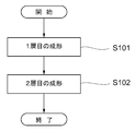
- It is a flowchart which shows the manufacturing method of a phase Fresnel lens.
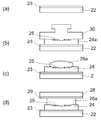
- FIG. 10 is a schematic diagram sequentially illustrating (a) to (d) regarding the molding process of the phase Fresnel lens according to the second embodiment.
- a phase Fresnel lens (hereinafter referred to as a PF lens 1), which is a contact multilayer type diffractive optical element, is shown in FIG.
- the PF lens 1 according to the first embodiment includes a glass substrate 2, a first resin layer 4 molded on the glass substrate 2, and a two-layer molded over the first resin layer 4. And a resin layer 6 of the eye.
- the glass substrate 2 is formed into a disk shape using a transparent glass material, and a primer made of a silane coupling agent is formed on one surface of the glass substrate 2 (the surface to be bonded to the first resin layer 4).
- Layer 3 is formed.
- the first resin layer 4 counted from the glass substrate 2 is formed into a disc shape using a transparent resin material, and is formed on one surface of the first resin layer 4 (the second resin layer 6 and the second resin layer 6).
- a diffraction grating 5 in which a plurality of annular zones are arranged concentrically is formed on the surface to be joined.
- the diameter of the first resin layer 4 is slightly smaller than the diameter of the glass substrate 2 (and larger than the effective diameter of the PF lens 1), and the outer periphery of the first resin layer 4 is the outer periphery of the glass substrate 2. It is located inside the part.
- the thickness of the first resin layer 4 is, for example, 50 ⁇ m to 400 ⁇ m.
- the second resin layer 6 counted from the glass substrate 2 is formed into a disk shape using a transparent resin material having a refractive index different from that of the first resin layer 4.
- the diameter of the second resin layer 6 is slightly smaller than the diameter of the first resin layer 4 (and larger than the effective diameter of the PF lens 1). It is located inside the outer peripheral part of the resin layer 4 of the layer.
- the thickness of the second resin layer 6 is, for example, 50 ⁇ m to 400 ⁇ m.
- the first resin layer 4 is formed and bonded on the glass substrate 2 (step S101).
- a mixture of silane coupling agent / ethyl alcohol / water (water slightly acidified with acetic acid) is mixed on one surface of the glass substrate 2.
- the liquid is applied over the entire surface by spin coating and baked to form the primer layer 3.
- a first mold (mold) 10 having a predetermined lattice shape is brought close to one surface of the glass substrate 2 on which the primer layer 3 is formed, and the first layer is placed in the gap as shown in FIG.
- An uncured resin material 4a for molding the resin layer 4 is filled.
- ultraviolet rays are irradiated from the other surface of the glass substrate 2 toward the resin material 4a by a predetermined irradiation amount (for example, 2000 to 4000 mJ / cm 2 ) to cure the uncured resin material 4a, Release.
- the grating shape of the first mold 10 is transferred to the resin material 4a to form the first resin layer 4 having the diffraction grating 5, and the first resin layer 4 becomes the primer layer 3. It is bonded to one surface of the glass substrate 2 via
- the resin material (resin material 4a) used for the first resin layer 4 is an ultraviolet curable resin, and its viscosity in an uncured state is 200 mPa ⁇ s to 800 mPa ⁇ s.
- the resin material 4 a is filled so that the outer peripheral portion of the first resin layer 4 is positioned inside the outer peripheral portion of the glass substrate 2.
- the second resin layer 6 is superimposed on the first resin layer 4 and molded and bonded (step S102).
- a second molding die (mold) 12 is brought into contact with the dropped resin material 6a and molded, and then cured by ultraviolet rays in the same manner as the first layer.
- the surface (transfer surface) of the second mold 12 is formed to be a flat surface.
- the surface (transfer surface) of the second mold 12 may be a spherical surface or an aspheric surface, and is determined according to the shape of the second resin layer 6.
- the second resin layer 6 is molded so as to be in close contact with the diffraction grating 5 on the other surface, and the second resin layer 6 is the first layer.
- the resin material (resin material 6a) used for the second resin layer 6 is an ultraviolet curable resin, and its viscosity in an uncured state is 3000 mPa ⁇ s to 7000 mPa ⁇ s.
- the second mold 12 is brought into contact with the resin material 6 a so that the outer peripheral portion of the second resin layer 6 is positioned inside the outer peripheral portion of the first resin layer 4. In this way, the PF lens 1 in which the two resin layers 4 and 6 are molded on the glass substrate 2 is manufactured.
- the outer peripheral portion of the second resin layer 6 is more than the outer peripheral portion of the first resin layer 4 located closer to the glass substrate 2 than the second resin layer 6. Since the outer peripheral portion of the second-layer resin material 6a protrudes from the first-layer resin layer 4 and does not entrain gas inside during molding, bubbles are mixed into the PF lens 1. Can be prevented.
- the viscosity of the resin material (resin material 6a) used when the second resin layer 6 is molded is 3000 mPa ⁇ s to 7000 mPa ⁇ s, and such a relatively high viscosity resin material is used as the second layer.
- the viscosity range of the resin material (resin material 6a) used when the second resin layer 6 is molded may be 4600 mPa ⁇ s to 5400 mPa ⁇ s.
- the resin material (resin material 4a) used for molding the first resin layer 4 has a viscosity of 200 mPa ⁇ s to 800 mPa ⁇ s, and has a lower viscosity than the second resin layer 6. Is used for the first resin layer 4, it is possible to prevent air bubbles from being mixed in the first resin layer 4.
- the viscosity range of the resin material (resin material 4a) used when the first resin layer 4 is molded may be 400 mPa ⁇ s to 600 mPa ⁇ s.
- each of the first resin layer 4 and the second resin layer 6 is 50 ⁇ m to 400 ⁇ m, and the two resin layers can be appropriately molded within such a range. it can.
- the PF lens 21 according to the second embodiment is overlapped on the first glass substrate 22, the first resin layer 24 molded on the first glass substrate 22, and the first resin layer 24.
- the second resin layer 26 formed in this manner and the second glass substrate 28 that is overlapped and bonded on the second resin layer 26 are configured.
- the first glass substrate 22 is formed into a disk shape using a transparent glass material, and one surface of the first glass substrate 22 (the surface to be bonded to the first resin layer 24) is silane.
- a primer layer 23 made of a coupling agent is formed.
- the first resin layer 24 counted from the first glass substrate 22 is formed into a disk shape using a transparent resin material, and is formed on one surface (second resin layer) of the first resin layer 24.
- a diffraction grating 25 in which a plurality of annular zones are arranged concentrically is formed on the surface to be joined to the layer 26.
- the diameter of the first resin layer 24 is slightly smaller than the diameter of the first glass substrate 22 (and larger than the effective diameter of the PF lens 21), and the outer periphery of the first resin layer 24 is the first. It is located inside the outer peripheral portion of the glass substrate 22.
- the thickness of the first resin layer 24 is, for example, 50 ⁇ m to 400 ⁇ m.
- the second resin layer 26 counted from the first glass substrate 22 is formed into a disk shape using a transparent resin material having a refractive index different from that of the first resin layer 24.
- the diameter of the second resin layer 26 is slightly smaller than the diameter of the first resin layer 24 (and larger than the effective diameter of the PF lens 21). It is located inside the outer peripheral part of the resin layer 24 of the layer.
- the thickness of the second resin layer 26 is, for example, 50 ⁇ m to 400 ⁇ m.
- the second glass substrate 28 is formed into a disk shape using a transparent glass material, and the other surface of the second glass substrate 28 (the surface to be bonded to the second resin layer 26) is silane.
- a primer layer 29 made of a coupling agent is formed.
- the first resin layer 24 is formed and bonded on the first glass substrate 22 (step S101).
- a silane coupling agent / ethyl alcohol / A mixed solution of water is applied over the entire surface by spin coating and baked to form the primer layer 23.
- a mold (mold) 30 having a predetermined lattice shape is brought close to one surface of the first glass substrate 22 on which the primer layer 23 is formed, and the first layer is placed in the gap as shown in FIG.
- An uncured resin material 24a for molding the resin layer 24 is filled.
- ultraviolet rays are irradiated from the other surface of the first glass substrate 22 toward the resin material 24a for a predetermined time (for example, 2 minutes), the uncured resin material 24a is cured, and then released. .
- the first resin layer 24 having the diffraction grating 25 is formed by transferring the grating shape of the molding die 30 to the resin material 24 a, and the first resin layer 24 is interposed via the primer layer 23. Bonded to one surface of the glass substrate 22.
- the resin material (resin material 24a) used for the first resin layer 24 is an ultraviolet curable resin, and its viscosity in an uncured state is 200 mPa ⁇ s to 800 mPa ⁇ s.
- the resin material 24 a is filled so that the outer peripheral portion of the first resin layer 24 is positioned inside the outer peripheral portion of the first glass substrate 22.
- the second resin layer 26 is overlaid on the first resin layer 24, and is molded and bonded (step S102).
- an uncured resin material 26a for molding the second resin layer 26 on the first resin layer 24 is formed.
- the second glass substrate 28 is brought into contact with the dropped resin material 26a and molded, and then cured in the same manner as in the first layer.
- a primer layer 29 is formed on the other surface of the second glass substrate 28 in the same manner as the first glass substrate 22, and the primer layer 29 is brought into contact with the resin material 26a to thereby form a second layer.
- the molding of the resin layer 26 and the bonding of the second glass substrate 28 to the second resin layer 26 can be performed simultaneously.
- the second resin layer 26 is molded so as to be in close contact with the diffraction grating 25 on the other surface, and the second resin layer 26 is bonded to one surface of the first resin layer 24.
- the second glass substrate 28 is bonded to one surface of the second resin layer 26 via the primer layer 29.
- the resin material (resin material 26a) used for the second resin layer 26 is an ultraviolet curable resin, and its viscosity in an uncured state is 3000 mPa ⁇ s to 7000 mPa ⁇ s.
- the second glass substrate 28 is brought into contact with the resin material 26 a so that the outer peripheral portion of the second resin layer 26 is positioned inside the outer peripheral portion of the first resin layer 24. In this way, the PF lens 21 in which the two resin layers 24 and 26 are formed between the two glass substrates 22 and 28 is manufactured.
- the second resin layer 26 is formed by bringing the second glass substrate 28 on which the primer layer 29 is formed into contact with the resin material 26 a to form the second resin layer 26. 26 and the second glass substrate 28 can be bonded to the second resin layer 26 at the same time. Therefore, when the PF lens 21 in which the two resin layers 24 and 26 are molded between the two glass substrates 22 and 28 is manufactured, it is not necessary to mold the second resin layer 26 with a molding die. The manufacturing process of the lens 21 can be simplified.
- the second glass substrate 28 on which the primer layer 29 is formed is brought into contact with the resin material 26a to form the second resin layer 26.
- the present invention is not limited to this. It is not a thing.
- the second glass substrate 8 may be stacked on the second resin layer 6 and bonded (bonded) using an adhesive 9.
- the PF lens 41 in which the two resin layers 4 and 6 are formed between the two glass substrates 2 and 8 is manufactured. In this case, it is not necessary to form a primer layer on the second glass substrate 8, and the manufacturing process of the PF lens 41 can be simplified.
- the present invention is not limited to this.
- three or more resin layers are formed.
- the present invention can be applied to a case where a plurality of layers are stacked on the base material for each layer.
- the viscosity of the resin material used when molding at least one of the plurality of layers can be 3000 mPa ⁇ s to 7000 mPa ⁇ s.
- the viscosity of the resin material can be 4600 mPa ⁇ s to 5400 mPa ⁇ s.
- a glass substrate is used as a base material.
- the present invention is not limited to this.
- a plastic substrate may be used as long as it is a transparent material.
- the glass substrate, the first resin layer, and the second resin layer are each formed in a disc shape.
- the present invention is not limited to this, and the glass substrate, one layer At least one surface (one or the other surface) of the second resin layer or the second resin layer may be a spherical surface or an aspheric surface.
- the outer peripheral portion may be cut and finished in a desired shape.
- the thickness of the second resin layer can be 50 ⁇ m to 1000 ⁇ m.
- the PF lens which is a kind of diffractive optical element
- the present invention is not limited to this. The present invention can be applied even to an element.
Landscapes
- Engineering & Computer Science (AREA)
- Physics & Mathematics (AREA)
- Mechanical Engineering (AREA)
- Health & Medical Sciences (AREA)
- Manufacturing & Machinery (AREA)
- Ophthalmology & Optometry (AREA)
- General Physics & Mathematics (AREA)
- Optics & Photonics (AREA)
- Diffracting Gratings Or Hologram Optical Elements (AREA)
- Casting Or Compression Moulding Of Plastics Or The Like (AREA)
- Optical Head (AREA)
Abstract
ガラス基板2の上に2つの樹脂層4,6を各層ごとに重ねて成形する光学素子1の製造方法であって、2つの樹脂層4,6のうちガラス基板2の方から数えて2層目の樹脂層6を成形する際、2層目の樹脂層6の外周部が該2層目の樹脂層6よりガラス基板2側に位置する1層目の樹脂層4の外周部よりも内側に位置するように成形を行う。
Description
本発明は、光学素子およびその製造方法に関する。
光学素子の製造には、成形加工がよく用いられる(例えば、特許文献1を参照)。例えば、密着複層型の回折光学素子である位相フレネルレンズの成形加工を行う場合、円盤状のガラス基板と該ガラス基板に近接させた成形型との間隙に第1の樹脂材を充填し、回折格子を有する1層目の樹脂層を成形する。さらに、1層目の樹脂層の上に滴下された第1の樹脂材と屈折率の異なる第2の樹脂材に対して成形型を押圧させ、2層目の樹脂層を成形する。これにより、密着複層型の回折光学素子を成形することができる。
しかしながら、上述した方法で複数の層を成形する際、2層目の層の外径が1層目の層の外径よりも大きいと、1層目の層からはみ出した2層目の層の外周部で気体を内側に巻き込みやすく、光学素子に気泡が混入して見映えが劣るおそれがあった。
本発明は、このような問題に鑑みてなされたものであり、気泡の混入を防止した光学素子の製造方法および光学素子を提供することを目的とする。
このような目的達成のため、本発明に係る光学素子の製造方法は、基材の上に複数の層を各層ごとに重ねて成形する光学素子の製造方法であって、前記複数の層のうち前記基材の方から数えて2層目以降の層を成形する際、成形を行う層の外周部が該層より前記基材側に位置する層の外周部よりも内側に位置するように前記成形を行うようになっている。
なお、上述の製造方法では、前記複数の層が2つの層であり、前記2つの層のうち前記基材の方から数えて2層目の層を成形する際、前記2層目の層の外周部が前記2層目の層より前記基材側に位置する1層目の層の外周部よりも内側に位置するように前記成形を行うことが好ましい。
また、上述の製造方法では、樹脂材料を用いて前記1層目の層および前記2層目の層をそれぞれ成形し、前記2層目の層を成形する際に用いられる樹脂材料の粘度が3000mPa・s以上7000mPa・s以下とすることができる。
また、上述の製造方法では、前記基材の上に回折格子を有する前記1層目の層を成形し、前記1層目の層の上に前記2層目の層を前記回折格子に密着させるように重ねて成形し、前記1層目の層を成形する際に用いられる樹脂材料の粘度が200mPa・s以上800mPa・s以下であることが好ましい。
また、上述の製造方法では、樹脂材料を用いて前記各層をそれぞれ成形し、前記複数の層のうち少なくともいずれかの層を成形する際に用いられる樹脂材料の粘度が3000mPa・s以上7000mPa・s以下とすることができる。
また、上述の製造方法では、前記各層の厚さがそれぞれ50μm以上400μm以下であることが好ましい。
また、第1の本発明に係る光学素子は、上述した光学素子の製造方法を用いて製造されるようになっている。
また、第2の本発明に係る光学素子は、基材と、前記基材の上に重ねて成形された複数の層とを備え、前記複数の層のうち前記基材の方から数えて2層目以降の層の外周部は、該層より前記基材側に位置する層の外周部よりも内側に位置するようになっている。
なお、第2の光学素子において、前記複数の層が2つの層であり、前記2つの層のうち前記基材の方から数えて2層目の層の外周部は、前記2層目の層より前記基材側に位置する1層目の層の外周部よりも内側に位置することが好ましい。
また、第2の光学素子において、前記1層目の層および前記2層目の層がそれぞれ樹脂材料を用いて成形され、前記2層目の層の成形に用いられる樹脂材料の粘度が3000mPa・s以上7000mPa・s以下とすることができる。
また、第2の光学素子において、前記基材の上に回折格子を有する前記1層目の層が成形され、前記1層目の層の上に前記2層目の層が前記回折格子に密着するように重ねて成形され、前記1層目の層の成形に用いられる樹脂材料の粘度が200mPa・s以上800mPa・s以下であることが好ましい。
また、第2の光学素子において、前記複数の層における各層がそれぞれ樹脂材料を用いて成形され、前記複数の層のうち少なくともいずれかの層の成形に用いられる樹脂材料の粘度が3000mPa・s以上7000mPa・s以下とすることができる。
また、第2の光学素子において、前記複数の層における各層の厚さがそれぞれ50μm以上400μm以下であることが好ましい。
本発明によれば、光学素子に気泡が混入するのを防止することができる。
以下、図面を参照して本発明の好ましい実施形態について説明する。第1実施形態における光学素子の一例として密着複層型の回折光学素子である位相フレネルレンズ(以下、PFレンズ1と称する)が図2に示されている。第1実施形態のPFレンズ1は、ガラス基板2と、ガラス基板2の上に成形された1層目の樹脂層4と、1層目の樹脂層4の上に重ねて成形された2層目の樹脂層6とを有して構成される。ガラス基板2は、透明のガラス材料を用いて円盤状に成形され、ガラス基板2の一方の面(1層目の樹脂層4と接合する方の面)には、シランカップリング剤からなるプライマー層3が形成されている。
ガラス基板2の方から数えて1層目の樹脂層4は、透明の樹脂材料を用いて円盤状に成形され、1層目の樹脂層4の一方の面(2層目の樹脂層6と接合する方の面)には、複数の輪帯が同心円状に並ぶ回折格子5が形成されている。1層目の樹脂層4の径は、ガラス基板2の径よりも若干小さく(且つ、PFレンズ1の有効径よりも大きく)、1層目の樹脂層4の外周部がガラス基板2の外周部よりも内側に位置するようになっている。また、1層目の樹脂層4の厚さは、例えば、50μm~400μmである。なお、各図において、説明容易化のため、回折格子5の輪帯の数を少なく記載しているが、実際の輪帯数は使用可能な程度に十分多いものとする。また、各図において、説明容易化のため、断面図のハッチングを省略している。
ガラス基板2の方から数えて2層目の樹脂層6は、1層目の樹脂層4と屈折率が異なる透明の樹脂材料を用いて円盤状に成形される。2層目の樹脂層6の径は、1層目の樹脂層4の径よりも若干小さく(且つ、PFレンズ1の有効径よりも大きく)、2層目の樹脂層6の外周部が1層目の樹脂層4の外周部よりも内側に位置するようになっている。また、2層目の樹脂層6の厚さは、例えば、50μm~400μmである。
以上のように構成されるPFレンズ1の製造方法について、図3に示すフローチャートを参照しながら説明する。まず、ガラス基板2の上に1層目の樹脂層4を成形し接合させる(ステップS101)。1層目の樹脂層4を成形する際、図1(a)に示すように、ガラス基板2の一方の面にシランカップリング剤/エチルアルコール/水(酢酸でやや酸性にした水)の混合液をスピンコートにより全面的に塗布し、ベーキングしてプライマー層3を形成する。プライマー層3を形成したガラス基板2の一方の面に所定の格子形状を有する第1の成形型(金型)10を近接させ、図1(b)に示すように、その間隙に1層目の樹脂層4を成形するための未硬化の樹脂材4aを充填する。この状態で、ガラス基板2の他方の面から樹脂材4aに向けて紫外線を所定の照射量(例えば、2000~4000mJ/cm2)だけ照射し、未硬化の樹脂材4aを硬化させた後、離型する。
これにより、第1の成形型10の格子形状が樹脂材4aに転写されて回折格子5を有する1層目の樹脂層4が成形されるとともに、当該1層目の樹脂層4がプライマー層3を介してガラス基板2の一方の面に接合される。なお、1層目の樹脂層4に用いられる樹脂材料(樹脂材4a)は紫外線硬化樹脂であり、未硬化状態での粘度は200mPa・s~800mPa・sである。また成形の際、1層目の樹脂層4の外周部がガラス基板2の外周部の内側に位置するように樹脂材4aの充填を行う。
次に、1層目の樹脂層4の上に2層目の樹脂層6を重ねて成形し接合させる(ステップS102)。2層目の樹脂層6を成形する際、図1(c)に示すように、1層目の樹脂層4の上に2層目の樹脂層6を成形するための未硬化の樹脂材6aを滴下し、図1(d)に示すように、滴下した樹脂材6aに第2の成形型(金型)12を当接させて成形した後、1層目と同様に紫外線硬化させて離型する。なお、第2の成形型12の表面(転写面)は平面となるように形成される。また、第2の成形型12の表面(転写面)は、球面や非球面であってもよく、2層目の樹脂層6の形状に応じて決定される。
これにより、図1(e)に示すように、他方の面で回折格子5に密着するように2層目の樹脂層6が成形されるとともに、当該2層目の樹脂層6が1層目の樹脂層4の一方の面に接合される。なお、2層目の樹脂層6に用いられる樹脂材料(樹脂材6a)は紫外線硬化樹脂であり、未硬化状態での粘度は3000mPa・s~7000mPa・sである。また成形の際、2層目の樹脂層6の外周部が1層目の樹脂層4の外周部の内側に位置するように第2の成形型12を樹脂材6aに当接させる。このようにして、ガラス基板2の上に2つの樹脂層4,6が成形されたPFレンズ1が製造される。
この結果、第1実施形態によれば、2層目の樹脂層6の外周部が該2層目の樹脂層6よりガラス基板2側に位置する1層目の樹脂層4の外周部よりも内側に位置するため、成形の際に2層目の樹脂材6aの外周部が1層目の樹脂層4からはみ出して内側に気体を巻き込むことがなく、PFレンズ1に気泡が混入するのを防止することができる。
また、2層目の樹脂層6を成形する際に用いられる樹脂材料(樹脂材6a)の粘度が3000mPa・s~7000mPa・sであり、このような比較的粘度の高い樹脂材料を2層目の樹脂層6に用いた場合、成形の際に2層目の樹脂材6aの外周部が1層目の樹脂層4からはみ出すと内側に気体を巻き込みやすいため、PFレンズ1に気泡が混入するのを効果的に防止することができる。なお、2層目の樹脂層6を成形する際に用いられる樹脂材料(樹脂材6a)の粘度の範囲を4600mPa・s~5400mPa・sにすることもできる。
また、1層目の樹脂層4を成形する際に用いられる樹脂材料(樹脂材4a)の粘度が200mPa・s~800mPa・sであり、2層目の樹脂層6よりも粘度が低い樹脂材料を1層目の樹脂層4に用いることで、1層目の樹脂層4で気泡が混入するのを防止することができる。なお、1層目の樹脂層4を成形する際に用いられる樹脂材料(樹脂材4a)の粘度の範囲を400mPa・s~600mPa・sにすることもできる。
また、1層目の樹脂層4および2層目の樹脂層6の厚さがそれぞれ50μm~400μmであり、各層の厚さがこのような範囲で、2つの樹脂層を適切に成形することができる。
次に、PFレンズの第2実施形態について図4を参照しながら説明する。第2実施形態のPFレンズ21は、第1のガラス基板22と、第1のガラス基板22の上に成形された1層目の樹脂層24と、1層目の樹脂層24の上に重ねて成形された2層目の樹脂層26と、2層目の樹脂層26の上に重ねて接合された第2のガラス基板28とを有して構成される。第1のガラス基板22は、透明のガラス材料を用いて円盤状に成形され、第1のガラス基板22の一方の面(1層目の樹脂層24と接合する方の面)には、シランカップリング剤からなるプライマー層23が形成されている。
第1のガラス基板22の方から数えて1層目の樹脂層24は、透明の樹脂材料を用いて円盤状に成形され、1層目の樹脂層24の一方の面(2層目の樹脂層26と接合する方の面)には、複数の輪帯が同心円状に並ぶ回折格子25が形成されている。1層目の樹脂層24の径は、第1のガラス基板22の径よりも若干小さく(且つ、PFレンズ21の有効径よりも大きく)、1層目の樹脂層24の外周部が第1のガラス基板22の外周部よりも内側に位置するようになっている。また、1層目の樹脂層24の厚さは、例えば、50μm~400μmである。
第1のガラス基板22の方から数えて2層目の樹脂層26は、1層目の樹脂層24と屈折率が異なる透明の樹脂材料を用いて円盤状に成形される。2層目の樹脂層26の径は、1層目の樹脂層24の径よりも若干小さく(且つ、PFレンズ21の有効径よりも大きく)、2層目の樹脂層26の外周部が1層目の樹脂層24の外周部よりも内側に位置するようになっている。また、2層目の樹脂層26の厚さは、例えば、50μm~400μmである。
第2のガラス基板28は、透明のガラス材料を用いて円盤状に成形され、第2のガラス基板28の他方の面(2層目の樹脂層26と接合する方の面)には、シランカップリング剤からなるプライマー層29が形成されている。
以上のように構成されるPFレンズ21の製造方法について説明する。第2実施形態に係るPFレンズ21の製造方法は、第1実施形態の場合と同様のフローであり、図3に示すフローチャートを用いて説明を行う。まず、第1のガラス基板22の上に1層目の樹脂層24を成形し接合させる(ステップS101)。第1のガラス基板22の上に1層目の樹脂層24を成形する際、図5(a)に示すように、第1のガラス基板22の一方の面にシランカップリング剤/エチルアルコール/水(酢酸でやや酸性にした水)の混合液をスピンコートにより全面的に塗布し、ベーキングしてプライマー層23を形成する。プライマー層23を形成した第1のガラス基板22の一方の面に所定の格子形状を有する成形型(金型)30を近接させ、図5(b)に示すように、その間隙に1層目の樹脂層24を成形するための未硬化の樹脂材24aを充填する。この状態で、第1のガラス基板22の他方の面から樹脂材24aに向けて紫外線を所定時間(例えば、2分間)だけ照射し、未硬化の樹脂材24aを硬化させた後、離型する。
これにより、成形型30の格子形状が樹脂材24aに転写されて回折格子25を有する1層目の樹脂層24が成形されるとともに、当該1層目の樹脂層24がプライマー層23を介してガラス基板22の一方の面に接合される。なお、1層目の樹脂層24に用いられる樹脂材料(樹脂材24a)は紫外線硬化樹脂であり、未硬化状態での粘度は200mPa・s~800mPa・sである。また成形の際、1層目の樹脂層24の外周部が第1のガラス基板22の外周部の内側に位置するように樹脂材24aの充填を行う。
次に、1層目の樹脂層24の上に2層目の樹脂層26を重ねて成形し接合させる(ステップS102)。2層目の樹脂層26を成形する際、図5(c)に示すように、1層目の樹脂層24の上に2層目の樹脂層26を成形するための未硬化の樹脂材26aを滴下し、図5(d)に示すように、滴下した樹脂材26aに第2のガラス基板28を当接させて成形した後、1層目と同様に紫外線硬化させる。なおこのとき、第1のガラス基板22と同様に第2のガラス基板28の他方の面にプライマー層29を形成し、このプライマー層29を樹脂材26aに当接させることにより、2層目の樹脂層26の成形と2層目の樹脂層26に対する第2のガラス基板28の接合を同時に行うことができる。
これにより、他方の面で回折格子25に密着するように2層目の樹脂層26が成形されるとともに、当該2層目の樹脂層26が1層目の樹脂層24の一方の面に接合され、また同時に、2層目の樹脂層26の一方の面にプライマー層29を介して第2のガラス基板28が接合される。なお、2層目の樹脂層26に用いられる樹脂材料(樹脂材26a)は紫外線硬化樹脂であり、未硬化状態での粘度は3000mPa・s~7000mPa・sである。また成形の際、2層目の樹脂層26の外周部が1層目の樹脂層24の外周部の内側に位置するように第2のガラス基板28を樹脂材26aに当接させる。このようにして、2つのガラス基板22,28の間に2つの樹脂層24,26が成形されたPFレンズ21が製造される。
この結果、第2実施形態によれば、第1実施形態の場合と同様の効果を得ることができる。また、第2実施形態によれば、プライマー層29が形成された第2のガラス基板28を樹脂材26aに当接させて2層目の樹脂層26を成形するため、2層目の樹脂層26の成形と2層目の樹脂層26に対する第2のガラス基板28の接合を同時に行うことができる。そのため、2つのガラス基板22,28の間に2つの樹脂層24,26が成形されたPFレンズ21を製造する場合に、成形型により2層目の樹脂層26を成形する必要が無く、PFレンズ21の製造工程を簡略化することができる。
なお、上述の第2実施形態において、プライマー層29が形成された第2のガラス基板28を樹脂材26aに当接させて2層目の樹脂層26を成形しているが、これに限られるものではない。例えば、図1(a)~(e)に示すように、上述の第1実施形態と同様にして、(第1の)ガラス基板2の上に2つの樹脂層4,6を成形した後、図1(f)に示すように、接着剤9を用いて第2のガラス基板8を2層目の樹脂層6の上に重ねて接着(接合)するようにしてもよい。このようにすれば、接着剤9を用いて第2のガラス基板8を接着するので、2つのガラス基板2,8の間に2つの樹脂層4,6が成形されたPFレンズ41を製造する場合に、第2のガラス基板8にプライマー層を形成する必要がなく、PFレンズ41の製造工程を簡略化することができる。
また、上述の各実施形態において、(第1の)ガラス基板の上に2つの樹脂層を成形しているが、これに限られるものではなく、例えば、3層以上の樹脂層を成形するようにしてもよく、基材の上に複数の層を各層ごとに重ねて成形する場合に、本発明を適用することができる。この場合、複数の層のうち少なくともいずれかの層を成形する際に用いられる樹脂材料の粘度を、3000mPa・s~7000mPa・sにすることができる。なお、樹脂材料の粘度を、4600mPa・s~5400mPa・sにすることもできる。
また、上述の各実施形態において、基材としてガラス基板を用いているが、これに限られるものではなく、例えば、プラスチック製の基板であってもよく、透明な材料であればよい。
また、上述の各実施形態において、ガラス基板、1層目の樹脂層、および2層目の樹脂層がそれぞれ円盤状に形成されているが、これに限られるものではなく、ガラス基板、1層目の樹脂層、および2層目の樹脂層の少なくともいずれかの面(一方もしくは他方の面)が球面もしくは非球面であってもよい。また、ガラス基板に1層目の樹脂層および2層目の樹脂層を成形した後、外周部をカットして所望の形状に仕上げるようにしてもよい。なお、2層目の樹脂層が非球面を有する場合、2層目の樹脂層の厚さを50μm~1000μmにすることができる。
また、上述の各実施形態において、回折光学素子の一種であるPFレンズを例に説明したが、これに限られるものではなく、一般的なフレネルレンズや、非球面レンズ、マイクロレンズアレイ等の光学素子であっても、本発明を適用可能である。
1 PFレンズ(第1実施形態) 2 ガラス基板(基材)
4 1層目の樹脂層 5 回折格子
6 2層目の樹脂層
21 PFレンズ(第2実施形態) 22 第1のガラス基板(基材)
24 1層目の樹脂層 25 回折格子
26 2層目の樹脂層
41 PFレンズ(変形例)
4 1層目の樹脂層 5 回折格子
6 2層目の樹脂層
21 PFレンズ(第2実施形態) 22 第1のガラス基板(基材)
24 1層目の樹脂層 25 回折格子
26 2層目の樹脂層
41 PFレンズ(変形例)
Claims (13)
- 基材の上に複数の層を各層ごとに重ねて成形する光学素子の製造方法であって、
前記複数の層のうち前記基材の方から数えて2層目以降の層を成形する際、成形を行う層の外周部が該層より前記基材側に位置する層の外周部よりも内側に位置するように前記成形を行うことを特徴とする光学素子の製造方法。 - 前記複数の層が2つの層であり、
前記2つの層のうち前記基材の方から数えて2層目の層を成形する際、前記2層目の層の外周部が前記2層目の層より前記基材側に位置する1層目の層の外周部よりも内側に位置するように前記成形を行うことを特徴とする請求項1に記載の光学素子の製造方法。 - 樹脂材料を用いて前記1層目の層および前記2層目の層をそれぞれ成形し、
前記2層目の層を成形する際に用いられる樹脂材料の粘度が3000mPa・s以上7000mPa・s以下であることを特徴とする請求項2に記載の光学素子の製造方法。 - 前記基材の上に回折格子を有する前記1層目の層を成形し、
前記1層目の層の上に前記2層目の層を前記回折格子に密着させるように重ねて成形し、
前記1層目の層を成形する際に用いられる樹脂材料の粘度が200mPa・s以上800mPa・s以下であることを特徴とする請求項3に記載の光学素子の製造方法。 - 樹脂材料を用いて前記各層をそれぞれ成形し、
前記複数の層のうち少なくともいずれかの層を成形する際に用いられる樹脂材料の粘度が3000mPa・s以上7000mPa・s以下であることを特徴とする請求項1に記載の光学素子の製造方法。 - 前記各層の厚さがそれぞれ50μm以上400μm以下であることを特徴とする請求項1から5のいずれか一項に記載の光学素子の製造方法。
- 請求項1から6のいずれか一項に記載の光学素子の製造方法を用いて製造されることを特徴とする光学素子。
- 基材と、前記基材の上に重ねて成形された複数の層とを備え、
前記複数の層のうち前記基材の方から数えて2層目以降の層の外周部は、該層より前記基材側に位置する層の外周部よりも内側に位置することを特徴とする光学素子。 - 前記複数の層が2つの層であり、
前記2つの層のうち前記基材の方から数えて2層目の層の外周部は、前記2層目の層より前記基材側に位置する1層目の層の外周部よりも内側に位置することを特徴とする請求項8に記載の光学素子。 - 前記1層目の層および前記2層目の層がそれぞれ樹脂材料を用いて成形され、
前記2層目の層の成形に用いられる樹脂材料の粘度が3000mPa・s以上7000mPa・s以下であることを特徴とする請求項9に記載の光学素子。 - 前記基材の上に回折格子を有する前記1層目の層が成形され、
前記1層目の層の上に前記2層目の層が前記回折格子に密着するように重ねて成形され、
前記1層目の層の成形に用いられる樹脂材料の粘度が200mPa・s以上800mPa・s以下であることを特徴とする請求項10に記載の光学素子。 - 前記複数の層における各層がそれぞれ樹脂材料を用いて成形され、
前記複数の層のうち少なくともいずれかの層の成形に用いられる樹脂材料の粘度が3000mPa・s以上7000mPa・s以下であることを特徴とする請求項8に記載の光学素子。 - 前記複数の層における各層の厚さがそれぞれ50μm以上400μm以下であることを特徴とする請求項8から12のいずれか一項に記載の光学素子。
Priority Applications (2)
| Application Number | Priority Date | Filing Date | Title |
|---|---|---|---|
| US14/111,551 US9557455B2 (en) | 2011-04-13 | 2012-04-04 | Optical element |
| CN201280018460.6A CN103476565B (zh) | 2011-04-13 | 2012-04-04 | 光学元件的制造方法以及光学元件 |
Applications Claiming Priority (2)
| Application Number | Priority Date | Filing Date | Title |
|---|---|---|---|
| JP2011-089203 | 2011-04-13 | ||
| JP2011089203A JP5834458B2 (ja) | 2011-04-13 | 2011-04-13 | 光学素子の製造方法および光学素子 |
Publications (1)
| Publication Number | Publication Date |
|---|---|
| WO2012140851A1 true WO2012140851A1 (ja) | 2012-10-18 |
Family
ID=47009046
Family Applications (1)
| Application Number | Title | Priority Date | Filing Date |
|---|---|---|---|
| PCT/JP2012/002358 Ceased WO2012140851A1 (ja) | 2011-04-13 | 2012-04-04 | 光学素子の製造方法および光学素子 |
Country Status (4)
| Country | Link |
|---|---|
| US (1) | US9557455B2 (ja) |
| JP (1) | JP5834458B2 (ja) |
| CN (1) | CN103476565B (ja) |
| WO (1) | WO2012140851A1 (ja) |
Cited By (1)
| Publication number | Priority date | Publication date | Assignee | Title |
|---|---|---|---|---|
| JP2012218394A (ja) * | 2011-04-13 | 2012-11-12 | Nikon Corp | 光学素子の製造方法および光学素子 |
Families Citing this family (8)
| Publication number | Priority date | Publication date | Assignee | Title |
|---|---|---|---|---|
| BR112016015347B8 (pt) * | 2013-12-31 | 2022-07-05 | Johnson & Johnson Consumer Inc | Processo para a formação de um produto de filme dotado de um formato em camadas múltiplas, produto de filme dotado de um formato em camadas múltiplas e aparelho para formar um produto de filme dotado de um formato em camadas múltiplas |
| MX392387B (es) | 2013-12-31 | 2025-03-24 | Johnson & Johnson Consumer Inc | Proceso para formar un producto de pelicula formado |
| EP3091968B1 (en) | 2013-12-31 | 2025-10-29 | Kenvue Brands LLC | Process for forming a multilayered shaped film |
| US10545269B2 (en) | 2016-09-13 | 2020-01-28 | Canon Kabushiki Kaisha | Diffractive optical element and method of manufacturing the same |
| IL304058B2 (en) | 2016-11-30 | 2025-10-01 | Molecular Imprints Inc | Light field display with multiple waveguides |
| CN110178058A (zh) | 2017-01-18 | 2019-08-27 | 日本板硝子株式会社 | 光学部件及光学部件的制造方法 |
| US10852460B2 (en) * | 2017-08-04 | 2020-12-01 | Canon Kabushiki Kaisha | Diffraction optical element, manufacturing method thereof, and optical apparatus |
| JP7418079B2 (ja) * | 2019-09-30 | 2024-01-19 | キヤノン株式会社 | 回折光学素子、光学機器、撮像装置 |
Citations (5)
| Publication number | Priority date | Publication date | Assignee | Title |
|---|---|---|---|---|
| JPH05100106A (ja) * | 1991-10-08 | 1993-04-23 | Dainippon Printing Co Ltd | フレネルレンズシートとその製造方法 |
| JP2009066827A (ja) * | 2007-09-12 | 2009-04-02 | Canon Inc | 光学素子の成形方法 |
| WO2009098846A1 (ja) * | 2008-02-06 | 2009-08-13 | Panasonic Corporation | 回折光学素子およびその製造方法 |
| WO2010032347A1 (ja) * | 2008-09-18 | 2010-03-25 | パナソニック株式会社 | 回折光学素子および回折光学素子の製造方法 |
| JP2010102353A (ja) * | 2003-06-19 | 2010-05-06 | Nikon Corp | 光学素子 |
Family Cites Families (13)
| Publication number | Priority date | Publication date | Assignee | Title |
|---|---|---|---|---|
| JPS61237609A (ja) * | 1985-04-16 | 1986-10-22 | Nisshinbo Ind Inc | 耐熱性部材の製造方法 |
| JP2638224B2 (ja) * | 1989-10-25 | 1997-08-06 | 日本電気株式会社 | 光学的記録担体の複製方法および複製装置 |
| JP2876277B2 (ja) * | 1993-07-20 | 1999-03-31 | キヤノン株式会社 | 複合型成形品 |
| US20010026399A1 (en) * | 1998-09-24 | 2001-10-04 | Masaaki Nakabayashi | Diffractive optical element and method of manufacture of the same |
| JP2001141918A (ja) | 1999-09-03 | 2001-05-25 | Canon Inc | 回折光学素子及びその製造方法 |
| JP4011811B2 (ja) * | 2000-01-14 | 2007-11-21 | Jsr株式会社 | 光硬化性樹脂組成物及び光学部材 |
| JP4232380B2 (ja) * | 2002-04-25 | 2009-03-04 | 株式会社ニコン | 複合型光学素子の製造方法 |
| JP4029208B2 (ja) | 2002-05-09 | 2008-01-09 | 株式会社ニコン | 光学素子の製造方法 |
| US20060029889A1 (en) * | 2004-08-06 | 2006-02-09 | Wang Tak K | Method to fabricate diffractive optics |
| CN100565250C (zh) * | 2005-02-22 | 2009-12-02 | 株式会社尼康 | 衍射光学元件 |
| JP4852400B2 (ja) * | 2006-11-27 | 2012-01-11 | シャープ株式会社 | 半導体記憶装置及び半導体装置並びに表示装置、液晶表示装置及び受像機 |
| JP2012128319A (ja) * | 2010-12-17 | 2012-07-05 | Canon Inc | 積層型回折光学素子及び積層型回折光学素子の製造方法 |
| JP5834458B2 (ja) * | 2011-04-13 | 2015-12-24 | 株式会社ニコン | 光学素子の製造方法および光学素子 |
-
2011
- 2011-04-13 JP JP2011089203A patent/JP5834458B2/ja active Active
-
2012
- 2012-04-04 US US14/111,551 patent/US9557455B2/en active Active
- 2012-04-04 CN CN201280018460.6A patent/CN103476565B/zh active Active
- 2012-04-04 WO PCT/JP2012/002358 patent/WO2012140851A1/ja not_active Ceased
Patent Citations (5)
| Publication number | Priority date | Publication date | Assignee | Title |
|---|---|---|---|---|
| JPH05100106A (ja) * | 1991-10-08 | 1993-04-23 | Dainippon Printing Co Ltd | フレネルレンズシートとその製造方法 |
| JP2010102353A (ja) * | 2003-06-19 | 2010-05-06 | Nikon Corp | 光学素子 |
| JP2009066827A (ja) * | 2007-09-12 | 2009-04-02 | Canon Inc | 光学素子の成形方法 |
| WO2009098846A1 (ja) * | 2008-02-06 | 2009-08-13 | Panasonic Corporation | 回折光学素子およびその製造方法 |
| WO2010032347A1 (ja) * | 2008-09-18 | 2010-03-25 | パナソニック株式会社 | 回折光学素子および回折光学素子の製造方法 |
Cited By (1)
| Publication number | Priority date | Publication date | Assignee | Title |
|---|---|---|---|---|
| JP2012218394A (ja) * | 2011-04-13 | 2012-11-12 | Nikon Corp | 光学素子の製造方法および光学素子 |
Also Published As
| Publication number | Publication date |
|---|---|
| JP2012218394A (ja) | 2012-11-12 |
| JP5834458B2 (ja) | 2015-12-24 |
| US20140036368A1 (en) | 2014-02-06 |
| US9557455B2 (en) | 2017-01-31 |
| CN103476565A (zh) | 2013-12-25 |
| CN103476565B (zh) | 2015-11-25 |
Similar Documents
| Publication | Publication Date | Title |
|---|---|---|
| JP5834458B2 (ja) | 光学素子の製造方法および光学素子 | |
| US8303866B2 (en) | Mass production of micro-optical devices, corresponding tools, and resultant structures | |
| JP6486042B2 (ja) | 積層型の回折光学素子 | |
| CN102037383B (zh) | 包括至少一个复制面的光学器件及其相关方法 | |
| JP2006076026A (ja) | 複合レンズ、複合レンズの製造方法、及びレンズモジュール | |
| JP2009028952A (ja) | 光学素子の製造方法 | |
| US8154794B2 (en) | Imaging lens and method of manufacturing the same | |
| JP2006106229A (ja) | 透過型光学素子の製造方法および透過型光学素子 | |
| JP2004013081A (ja) | 複合型光学素子、複合型光学素子の製造方法、及び光学装置 | |
| JP6823381B2 (ja) | 回折光学素子、回折格子を備えた光学機器及び回折格子を備えたカメラ | |
| JP4781001B2 (ja) | 複合レンズの製造方法 | |
| JP4029208B2 (ja) | 光学素子の製造方法 | |
| JP2007212547A (ja) | 光学素子の製造方法および光学素子 | |
| JP2012128319A (ja) | 積層型回折光学素子及び積層型回折光学素子の製造方法 | |
| TWI506301B (zh) | 微透鏡結構及其製造方法 | |
| KR100985568B1 (ko) | 스탬프를 이용한 렌즈 제조 방법 | |
| JP6079029B2 (ja) | 光学素子の製造方法および製造装置 | |
| JP2006263975A (ja) | 光学素子の製造方法 | |
| KR101352055B1 (ko) | 일체형 광학 필름 제조 방법 및 일체형 광학 필름 | |
| JP6119135B2 (ja) | 光学素子の製造方法および光学素子 | |
| CN103974820A (zh) | 透镜单元的制造方法以及透镜单元 | |
| JP2006220739A (ja) | セラミックスハイブリッドレンズ | |
| WO2009110185A1 (ja) | 複合光学素子及びその製造方法 | |
| JP2009137140A (ja) | 光学素子の製造方法及び光学素子 | |
| JP2008217915A5 (ja) |
Legal Events
| Date | Code | Title | Description |
|---|---|---|---|
| 121 | Ep: the epo has been informed by wipo that ep was designated in this application |
Ref document number: 12771814 Country of ref document: EP Kind code of ref document: A1 |
|
| WWE | Wipo information: entry into national phase |
Ref document number: 14111551 Country of ref document: US |
|
| NENP | Non-entry into the national phase |
Ref country code: DE |
|
| 122 | Ep: pct application non-entry in european phase |
Ref document number: 12771814 Country of ref document: EP Kind code of ref document: A1 |