WO2012140699A1 - 機械の潤滑装置 - Google Patents
機械の潤滑装置 Download PDFInfo
- Publication number
- WO2012140699A1 WO2012140699A1 PCT/JP2011/002219 JP2011002219W WO2012140699A1 WO 2012140699 A1 WO2012140699 A1 WO 2012140699A1 JP 2011002219 W JP2011002219 W JP 2011002219W WO 2012140699 A1 WO2012140699 A1 WO 2012140699A1
- Authority
- WO
- WIPO (PCT)
- Prior art keywords
- oil
- filter
- fine particles
- engine
- value
- Prior art date
- Legal status (The legal status is an assumption and is not a legal conclusion. Google has not performed a legal analysis and makes no representation as to the accuracy of the status listed.)
- Ceased
Links
Images




Classifications
-
- F—MECHANICAL ENGINEERING; LIGHTING; HEATING; WEAPONS; BLASTING
- F01—MACHINES OR ENGINES IN GENERAL; ENGINE PLANTS IN GENERAL; STEAM ENGINES
- F01M—LUBRICATING OF MACHINES OR ENGINES IN GENERAL; LUBRICATING INTERNAL COMBUSTION ENGINES; CRANKCASE VENTILATING
- F01M1/00—Pressure lubrication
- F01M1/10—Lubricating systems characterised by the provision therein of lubricant venting or purifying means, e.g. of filters
-
- B—PERFORMING OPERATIONS; TRANSPORTING
- B01—PHYSICAL OR CHEMICAL PROCESSES OR APPARATUS IN GENERAL
- B01J—CHEMICAL OR PHYSICAL PROCESSES, e.g. CATALYSIS OR COLLOID CHEMISTRY; THEIR RELEVANT APPARATUS
- B01J20/00—Solid sorbent compositions or filter aid compositions; Sorbents for chromatography; Processes for preparing, regenerating or reactivating thereof
- B01J20/02—Solid sorbent compositions or filter aid compositions; Sorbents for chromatography; Processes for preparing, regenerating or reactivating thereof comprising inorganic material
- B01J20/06—Solid sorbent compositions or filter aid compositions; Sorbents for chromatography; Processes for preparing, regenerating or reactivating thereof comprising inorganic material comprising oxides or hydroxides of metals not provided for in group B01J20/04
- B01J20/08—Solid sorbent compositions or filter aid compositions; Sorbents for chromatography; Processes for preparing, regenerating or reactivating thereof comprising inorganic material comprising oxides or hydroxides of metals not provided for in group B01J20/04 comprising aluminium oxide or hydroxide; comprising bauxite
-
- B—PERFORMING OPERATIONS; TRANSPORTING
- B01—PHYSICAL OR CHEMICAL PROCESSES OR APPARATUS IN GENERAL
- B01J—CHEMICAL OR PHYSICAL PROCESSES, e.g. CATALYSIS OR COLLOID CHEMISTRY; THEIR RELEVANT APPARATUS
- B01J41/00—Anion exchange; Use of material as anion exchangers; Treatment of material for improving the anion exchange properties
- B01J41/02—Processes using inorganic exchangers
-
- C—CHEMISTRY; METALLURGY
- C10—PETROLEUM, GAS OR COKE INDUSTRIES; TECHNICAL GASES CONTAINING CARBON MONOXIDE; FUELS; LUBRICANTS; PEAT
- C10M—LUBRICATING COMPOSITIONS; USE OF CHEMICAL SUBSTANCES EITHER ALONE OR AS LUBRICATING INGREDIENTS IN A LUBRICATING COMPOSITION
- C10M175/00—Working-up used lubricants to recover useful products ; Cleaning
- C10M175/0058—Working-up used lubricants to recover useful products ; Cleaning by filtration and centrifugation processes; apparatus therefor
-
- C—CHEMISTRY; METALLURGY
- C10—PETROLEUM, GAS OR COKE INDUSTRIES; TECHNICAL GASES CONTAINING CARBON MONOXIDE; FUELS; LUBRICANTS; PEAT
- C10M—LUBRICATING COMPOSITIONS; USE OF CHEMICAL SUBSTANCES EITHER ALONE OR AS LUBRICATING INGREDIENTS IN A LUBRICATING COMPOSITION
- C10M175/00—Working-up used lubricants to recover useful products ; Cleaning
- C10M175/0091—Treatment of oils in a continuous lubricating circuit (e.g. motor oil system)
-
- F—MECHANICAL ENGINEERING; LIGHTING; HEATING; WEAPONS; BLASTING
- F01—MACHINES OR ENGINES IN GENERAL; ENGINE PLANTS IN GENERAL; STEAM ENGINES
- F01M—LUBRICATING OF MACHINES OR ENGINES IN GENERAL; LUBRICATING INTERNAL COMBUSTION ENGINES; CRANKCASE VENTILATING
- F01M11/00—Component parts, details or accessories, not provided for in, or of interest apart from, groups F01M1/00 - F01M9/00
- F01M11/10—Indicating devices; Other safety devices
-
- F—MECHANICAL ENGINEERING; LIGHTING; HEATING; WEAPONS; BLASTING
- F01—MACHINES OR ENGINES IN GENERAL; ENGINE PLANTS IN GENERAL; STEAM ENGINES
- F01M—LUBRICATING OF MACHINES OR ENGINES IN GENERAL; LUBRICATING INTERNAL COMBUSTION ENGINES; CRANKCASE VENTILATING
- F01M11/00—Component parts, details or accessories, not provided for in, or of interest apart from, groups F01M1/00 - F01M9/00
- F01M11/10—Indicating devices; Other safety devices
- F01M2011/14—Indicating devices; Other safety devices for indicating the necessity to change the oil
- F01M2011/1466—Indicating devices; Other safety devices for indicating the necessity to change the oil by considering quantity of soot
-
- F—MECHANICAL ENGINEERING; LIGHTING; HEATING; WEAPONS; BLASTING
- F16—ENGINEERING ELEMENTS AND UNITS; GENERAL MEASURES FOR PRODUCING AND MAINTAINING EFFECTIVE FUNCTIONING OF MACHINES OR INSTALLATIONS; THERMAL INSULATION IN GENERAL
- F16N—LUBRICATING
- F16N2200/00—Condition of lubricant
-
- F—MECHANICAL ENGINEERING; LIGHTING; HEATING; WEAPONS; BLASTING
- F16—ENGINEERING ELEMENTS AND UNITS; GENERAL MEASURES FOR PRODUCING AND MAINTAINING EFFECTIVE FUNCTIONING OF MACHINES OR INSTALLATIONS; THERMAL INSULATION IN GENERAL
- F16N—LUBRICATING
- F16N2250/00—Measuring
-
- F—MECHANICAL ENGINEERING; LIGHTING; HEATING; WEAPONS; BLASTING
- F16—ENGINEERING ELEMENTS AND UNITS; GENERAL MEASURES FOR PRODUCING AND MAINTAINING EFFECTIVE FUNCTIONING OF MACHINES OR INSTALLATIONS; THERMAL INSULATION IN GENERAL
- F16N—LUBRICATING
- F16N39/00—Arrangements for conditioning of lubricants in the lubricating system
- F16N39/06—Arrangements for conditioning of lubricants in the lubricating system by filtration
-
- G—PHYSICS
- G01—MEASURING; TESTING
- G01N—INVESTIGATING OR ANALYSING MATERIALS BY DETERMINING THEIR CHEMICAL OR PHYSICAL PROPERTIES
- G01N21/00—Investigating or analysing materials by the use of optical means, i.e. using sub-millimetre waves, infrared, visible or ultraviolet light
- G01N21/17—Systems in which incident light is modified in accordance with the properties of the material investigated
- G01N21/47—Scattering, i.e. diffuse reflection
- G01N21/49—Scattering, i.e. diffuse reflection within a body or fluid
- G01N21/53—Scattering, i.e. diffuse reflection within a body or fluid within a flowing fluid, e.g. smoke
Definitions
- the present invention relates to a lubrication device for supplying oil to one or more supply parts of a machine such as an internal combustion engine.
- Patent Document 1 discloses a filter medium for a bypass oil filter for an internal combustion engine.
- this filter medium contains a hydrotalcite compound represented by the following formula (1).
- x and y are integers satisfying 3 ⁇ x ⁇ 20 and 0 ⁇ y ⁇ 2, and m represents an integer.
- Patent Document 2 discloses an optical liquid detection device. This device is applied to an internal combustion engine, and includes an optical detector including a light emitting diode (LED) as a light emitting unit, a photodiode (PD) as a light receiving unit, and a prism, and a float floating on an oil surface. According to the description of Patent Document 2, this apparatus determines the deterioration of oil as described below.
- LED light emitting diode
- PD photodiode
- Patent Document 2 when oil is circulated in the engine by starting the engine, the incident light to the prism emitted from the LED is totally reflected on the contact surface in contact with the oil of the prism. The reflected light is further totally reflected by the reflection film at the bottom of the prism, and this reflected light is further totally reflected by another contact surface, and the reflected light that has been totally reflected again enters the PD. During total reflection, the reflected light varies depending on the amount of particles in the oil. Therefore, in the apparatus of Patent Document 2, the deterioration of the oil is determined based on the change in the intensity of the reflected light received by the PD.
- the filter can have a substance such as hydrotalcite, when the filter is deteriorated, it is possible that a part of the substance flows out from the filter. Substances flowing out from the filter may exist as fine particles in the oil, and there is a concern that such fine particles may affect wear between machine parts. Therefore, it is desirable to replace the filter in such a case.
- an object of the present invention is to suitably determine deterioration of a filter including hydrotalcite provided in a lubricating device for a machine such as an internal combustion engine.
- One aspect of the present invention is a filter provided in an oil passage, the filter including one or more reactants containing hydrotalcite, and the deterioration of the filter based on the amount of fine particles in the oil in the oil passage.
- a machine lubrication device including a filter deterioration determination device for determination.
- the filter when the filter deteriorates as the amount of fine particles in the oil derived from the reactant containing hydrotalcite increases, the filter deteriorates based on the increased amount of fine particles in the oil in the oil passage. Can be determined.
- the filter deterioration determination device is configured to detect a value corresponding to the amount of fine particles in oil in the oil passage, and to a value detected by the fine particle amount detection device. And a determination device for determining deterioration of the filter based on the determination device.
- the fine particle amount detection device may be configured to detect a dispersion concentration of fine particles in oil or a value corresponding to the dispersion concentration as the value.
- the fine particle amount detection device may be configured to detect a value corresponding to a change amount of the fine particles in the oil as the value.
- the fine particle amount detection device includes a light emitting unit for irradiating light toward the oil in the oil passage, a light receiving unit for receiving light from the oil irradiated with light from the light emitting unit, and the light receiving unit And a value calculation unit that calculates a value corresponding to the amount of fine particles in the oil based on the light received by.
- the fine particle amount detection device may be provided in an oil reservoir in the oil passage.
- the particulate amount detection device can be provided between the oil filter and the oil reservoir.
- the above-described mechanical lubrication device may further include an exchange promoting means for accelerating the exchange of the filter when the filter degradation judging device determines that the filter has degraded.
- the machine is an internal combustion engine.
- FIG. 1 is a conceptual diagram of an internal combustion engine to which a first embodiment of the present invention is applied.
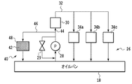
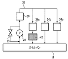
- FIG. 2 is a conceptual diagram of a part of the lubricating device for the internal combustion engine of FIG.
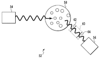
- FIG. 3 is a conceptual diagram of a detection unit in the lubricating device for the internal combustion engine of FIG.
- FIG. 4 is a diagram conceptually showing a flow of filter deterioration determination in the first embodiment.
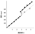
- FIG. 5 is a graph showing an example of an experimental result regarding the first embodiment.
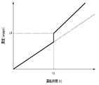
- FIG. 6 is a graph conceptually showing a change in the dispersion concentration of fine particles in oil, constructed from the experimental results shown in FIG.
- FIG. 7 is a conceptual diagram of an internal combustion engine to which the second embodiment of the present invention is applied.
- FIG. 1 is a conceptual diagram of an internal combustion engine to which a first embodiment of the present invention is applied.
- FIG. 2 is a conceptual diagram of a part of the lubricating device for the internal combustion engine of FIG.
- FIG. 8 is a graph conceptually showing a change in the dispersion concentration of the fine particles in the oil, which is constructed from the experimental results regarding the second embodiment.
- FIG. 9 is a conceptual diagram of a part of the lubricating device for an internal combustion engine according to the third embodiment.
- FIG. 10 is a conceptual diagram of a part of the lubricating device for an internal combustion engine according to the fourth embodiment.
- FIG. 11 is a conceptual diagram of a part of the lubricating device for an internal combustion engine according to the fifth embodiment.
- One embodiment of the present invention provides a mechanical lubrication device.
- This machine lubrication device can be applied to a machine such as an internal combustion engine, and includes a filter provided in an oil passage.
- the filter includes one or more reactants, and each of the one or more reactants can include hydrotalcite.
- the reactant included in the filter may be composed only of hydrotalcite or may contain a substance other than hydrotalcite.
- the machine lubrication device includes a filter deterioration determination device.
- the filter deterioration determination device is configured to determine the deterioration of the filter based on the amount of fine particles in the oil in the oil passage.
- This filter deterioration determination device is configured to detect a value corresponding to the amount of fine particles in oil in the oil passage, and a filter based on the value detected by the fine particle amount detection device.
- a determination device for determining deterioration For example, the fine particle amount detection device may detect a value corresponding to the amount of change in the amount of fine particles in oil as such a value.
- the fine particle amount detection device includes a light emitting unit for irradiating light such as laser light toward the oil in the oil passage, and a light receiving unit for receiving light from the oil irradiated with light from the light emitting unit. And a value calculation unit that calculates a value corresponding to the amount of fine particles in the oil based on the light received by the light receiving unit. For example, the deterioration determination device can determine that the filter has deteriorated by comparing such a detected value with a predetermined value.
- FIG. 1 is a conceptual diagram of an internal combustion engine (hereinafter referred to as an engine) 10 to which a first embodiment according to the present invention is applied.
- the engine 10 is mounted on a vehicle.
- the engine 10 is an in-line four-cylinder engine.
- the engine to which the present invention is applied is not limited to the number of cylinders and the cylinder arrangement type, and may be a spark ignition engine or a compression ignition engine. Absent.
- the engine 10 includes a cylinder block 12 integrally provided with a crankcase, a cylinder head 14, a head cover 16 that covers the cylinder head 14 from above, and an oil pan 18.
- a mixture of air taken in through the intake passage 20 through the throttle valve 22 and fuel injected from a fuel injection valve (not shown) is combusted in the combustion chamber, and exhaust is discharged through the exhaust passage 24.
- the lubrication device 26 of the engine 10 is configured to supply oil to one or more supply parts in the engine 10.
- the one or more supply parts include a plurality of supply parts including a plurality of sliding portions in the engine 10.
- a part of the lubrication device 26 is schematically illustrated in FIG. 1, but another part of the lubrication device 26 is further schematically illustrated in FIG.
- the engine 10 and the lubricating device 26 will be described with reference to FIGS. 1 and 2.
- the lubrication device 26 includes a strainer and an oil pump 28 (not shown), and the oil stored in the oil pan 18 that is an oil storage unit is pumped (sucked) by the oil pump 28 through the strainer.
- the pump 28 is configured to mechanically drive by receiving power from the camshaft or crankshaft in accordance with the operation of the engine 10, and for releasing oil to the oil pan 18 side at high hydraulic pressure.
- a relief valve 29 is provided.
- the oil pump as an oil supply apparatus can be provided with two or more without being limited to one, The operation structure of these one or more oil supply apparatuses can be a mechanical type or an electric type.
- the oil pumped up as described above by the oil pump 28 passes through an oil filter 30 and passes through an oil passage 32 formed in the engine 10 (including a plurality of oil passages corresponding to each supply site).
- Oil passage 32 formed in the engine 10 (including a plurality of oil passages corresponding to each supply site).
- the lubricating oil that is, the oil thus supplied to the plurality of portions is finally returned to the oil pan 18 by its own weight. In this way, the oil is circulated in the lubricating device 26.
- the space where oil can circulate in the engine 10 is referred to herein as an “oil passage”.
- An oil return passage 36 is formed in the cylinder block 12 and the cylinder head 14 so as to communicate the inside of the head cover 16 or the cylinder head 14 with the inside of the crankcase, that is, the oil pan 18.
- the oil return passage 36 is, for example, a passage for returning (dropping) oil that has finished lubrication of the valve system from the cylinder head 14 into the oil pan 18.
- an air passage 38 that connects the inside of the crankcase, that is, the oil pan 18 and the head cover 16 or the cylinder head 14 is formed.
- the air passage 38 also plays a role of causing the blow-by gas in the crankcase to move upward toward the head cover 16.
- the oil return passage 36 and the air passage 38 can each function as an oil passage and can also function as an air passage.
- the number of oil return passages 36 and the number of air passages 38 may be any number.
- the blow-by gas is a gas that leaks into the crankcase from the gap between the piston ring of the piston and the cylinder bore of the cylinder block 12.
- This blow-by gas contains a large amount of hydrocarbons and moisture. For this reason, too much blow-by gas causes premature deterioration of engine oil and rust inside the engine. Further, since the blow-by gas contains hydrocarbons, it is not environmentally preferable to release it to the atmosphere as it is. Therefore, the engine 10 includes a known blow-by gas recirculation device (not shown). After the blow-by gas is introduced into the head cover 16, it is forcibly returned to the intake system using the intake negative pressure and supplied to the combustion chamber.
- blow-by gas contains, for example, NOx, SOx and moisture.
- the head cover 16 is difficult to transmit heat from the engine and its outer surface is exposed to the outside air and cooled by cooling air or the like, so that condensed water due to condensation or the like tends to be generated on the inner surface of the head cover 16. Therefore, particularly in the head cover 16, acidic substances such as nitric acid and sulfuric acid are likely to be formed by the reaction.
- acidic substances can be mixed with lubricating oil, that is, engine oil, and can promote generation, adhesion, and accumulation of sludge precursors and sludge inside the engine.
- Such sludge can be caused by oil deterioration, and can also cause oil deterioration. Therefore, suppressing the generation of sludge precursors and sludge, etc., suppresses oil deterioration.
- the oil deterioration suppressing device 40 applied to the lubricating device 26 of the engine 10 has an oil filter 42 for removing such acidic substances, that is, acidic components from the engine oil.
- the oil filter 42 as a filtering member is provided in a bypass passage 46 that is separated from the main oil passage 44 in the oil passage 32 and communicates with the oil pan 18.
- the bypass passage 46 is included in the oil passage 32 and can be referred to as a sub oil passage with respect to the main oil passage 44 for supplying oil to the supply parts 34 a, 34 b, 34 c of the engine 10.
- the oil filter 42 and a part of the bypass passage 46 are drawn on the outside of the engine body 10 ′ in order to exaggerate the main part of the oil deterioration suppressing device 40 including the oil filter 42.
- the installation position of the oil filter 42 and the like is not limited to the position shown in FIG. 1 and can be changed to various places.
- the outer side of each part of the engine body 10 ′ It is possible to be defined in a part away from the inside or inside each part of the engine body 10 ′.
- the oil filter 42 is provided so as to be replaceable. In this case, it is preferable that the oil filter 42 is positioned at an easily replaceable position. The oil filter 42 can be replaced at an appropriate time.
- the oil filter 42 is configured to adsorb a predetermined acidic component in the oil.
- the oil filter 42 includes a support member 48 and a large number of (a plurality of) reactants supported or contained therein.
- the reactant is provided in the oil filter 42 as an oil additive.
- Each of the reactants is granular and is composed of hydrotalcite. In particular, here each of the reactants is essentially composed only of hydrotalcite.
- the reactant is supported so as to be sandwiched between filter paper members as a part of the support member 48, and further accommodated in a case member as a part of the support member 48.
- the support member such as the case member of the oil filter 42 is configured so that oil can appropriately pass therethrough.
- each reactant can have a size on the order of 5-30 ⁇ m.
- the support member 48 of the oil filter 42 may be a mesh bag, a three-dimensional mesh structure, a porous structure, a cylindrical structure, or the like, and a plurality of reactants may be provided in at least one of the inside and the gap. Can be trapped or held.
- the one or more reactants supported by such a support member can be in a shape other than grains.
- the one or more reactants supported by such a support member can be a single or a plurality of blocks that are consolidated together at least prior to use.
- the hydrotalcite as a reactant included in or contained in the oil filter 42 has a layered structure, and has a property of incorporating an anion, that is, an anion, between layers of a skeleton portion composed mainly of a metal component. .
- a hydrotalcite can have a function of taking in, that is, adsorbing a new anion and releasing the anion that has been present between the layers.
- hydrotalcite is an ion exchanger (ion exchange material) or acts as an ion exchanger.
- Such hydrotalcite has a function of adsorbing predetermined ions, that is, ionic components, particularly acidic components (such as nitrate ions) in the oil.
- nitrate ions NO 3 ⁇
- SO 4 2 ⁇ sulfate ions
- the acidic component that is desired to be removed from the oil by hydrotalcite is not only nitrate ions (NO 3 ⁇ ) and sulfate ions (SO 4 2 ⁇ ), but also acetic acid that can be generated based on, for example, blowby gas.
- Ions CH 3 COO ⁇
- formate ions HCOO ⁇
- the component that is desired to be removed from the oil by hydrotalcite includes sulfuric acid that is an acid decomposition product derived from this additive when ZnDTP (Zinc Dialkyldithiophosphate) is used as the oil additive.
- ZnDTP Zinc Dialkyldithiophosphate
- Each of the reactants may have a function of adsorbing or capturing at least one component selected from a group including these or a group consisting of these.
- the oil filter 42 may include various hydrotalcites having a layered structure as described above, that is, reactants containing hydrotalcite compounds.
- hydrotalcites having a layered structure as described above, that is, reactants containing hydrotalcite compounds.
- “Mg 6 Al 2 (OH) (CO 3 ) 16 ” (hereinafter referred to as “HT”) manufactured by Wako Pure Chemical Industries, Ltd. may be used as the hydrotalcite.
- This hydrotalcite, or HT is a layered compound containing a layer of a skeleton part composed mainly of Al and Mg, and an anion sandwiched between the layers.
- the filter 42 may gradually release fine particles. For example, when one or more holes of the support member 48 of the oil filter 42 are enlarged, some of the reactants held by the support member 48 are transferred to the oil filter 42 through the enlarged hole. From the oil to the oil passage 32 may occur. Or, when a part of the surface layer of the reactant held by the support member 48 is peeled off from the reactant, it may flow out from the oil filter 42 to the oil passage 32.
- the reactant itself or one or more reactant parts flowing out from the oil filter 42 to the oil passage 32 can be mixed with the oil in the oil passage 32 and float. That is, the substance flowing out from the oil filter 42 can exist as fine particles in the oil.
- the oil deterioration suppressing device 40 of the lubricating device 26 further includes a filter deterioration determining device 50 that determines deterioration of the filter 42 based on the amount of the fine particles in the oil passage 32.
- the filter deterioration determining device 50 is configured to detect a value corresponding to the amount of fine particles in oil in the oil passage 32, and to filter based on the value detected by the fine particle amount detecting device. And a determination device for determining the deterioration of 42.
- the fine particle amount detection device includes a detection unit 52 as a sensor and a value calculation unit. The detection unit 52 is provided in the oil passage 32, and is particularly provided in the oil pan 18 here.
- the configuration of the detection unit 52 will be described with reference to the conceptual diagram of FIG.
- the detection unit 52 has a configuration constructed based on the principle of the laser diffraction method.
- the detection unit 52 includes a light emitting unit 54 and a light receiving unit 56.
- the light emitting unit 54 is configured to irradiate light, particularly here, laser light, into the oil 58 of the oil passage 32.
- the light receiving unit 56 is configured to receive scattered light from oil derived from light emitted from the light emitting unit 54 into the oil.
- an optical system unit 60 is provided on the front side of the light receiving unit 56, and the optical system unit 60 includes one or more pinholes, and two pinholes 62 and 64 in FIG.
- the optical system unit 60 is configured to control the interference of scattered light. Note that the optical system unit 60 may include one or more slits.
- the concentration of the fine particles in the oil can be calculated based on the scattered light received by the light receiving unit 56.
- the principle of such a laser diffraction method is well known, further explanation thereof is omitted here.
- the principle of the dynamic light scattering method is further used in calculating the dispersion concentration of the fine particles in the oil based on the laser diffraction method. Based on the dynamic light scattering method, the particle size and particle size distribution of the fine particles dispersed in the oil can be calculated from the scattered light received by the light receiving unit 56.
- the dispersion concentration of the fine particles in the oil can be obtained more accurately.
- the dynamic light scattering method is also well-known, the further description here is abbreviate
- the oil temperature in the Einstein-Stokes equation used to determine the particle size of the fine particles in the oil by the dynamic light scattering method is obtained by searching the data stored in the storage device in advance based on the engine coolant temperature. Desired.
- the fine particle amount detection device is configured based on this laser diffraction method or a combination of the laser diffraction method and the dynamic light scattering method. That is, based on the scattered light information or information signal obtained by the detection unit 52 having the above-described configuration of the fine particle amount detection device, the value calculation unit of the fine particle amount detection device uses data and an arithmetic expression determined by the above principle. Thus, the dispersion concentration of the fine particles in the oil is obtained.
- the function of the value calculation unit is here carried out by an electronic control unit (hereinafter referred to as ECU) 70.
- the ECU 70 is provided in the engine 10 and substantially functions as various control devices (control means) and various detection devices (detection means).
- the ECU 70 is configured by a computer including a storage device including a CPU, ROM, and RAM, an A / D converter, an input interface, an output interface, and the like.
- the input interface includes various sensors including the detection unit 52, an engine speed sensor 72 for detecting the engine speed, an engine load sensor 74 for detecting the engine load, a vehicle speed sensor 76, a water temperature sensor 78, and the like. Electrically connected.
- the engine rotation speed sensor 72 for example, a crank angle sensor can be used.
- As the engine load sensor 74 an air flow meter, an accelerator opening sensor, or the like can be used.
- the engine coolant temperature can be detected based on the output of the water temperature sensor 78. Based on the outputs (detection signals) from these various sensors, the ECU 70 is electrically connected to the fuel injection valve and the throttle valve 22 from the output interface so that the engine 10 can be smoothly operated or operated according to a preset program. An operation signal (driving signal) is output to the actuator for use.
- the part responsible for the function of the value calculation unit of the ECU 70 calculates the dispersion concentration of the fine particles in the oil based on the output of the detection unit 52, that is, the information on the scattered light detected by the detection unit 52. Data and arithmetic expressions used for this calculation are determined based on the above principle and stored in advance in a storage device.
- the concentration of the fine particles is correlated with the amount of fine particles in the oil. Therefore, the concentration of fine particles in oil is used here as a value corresponding to the amount of fine particles in oil.
- the ECU 70 functions as a determination device that determines the deterioration of the filter 42.
- step S401 a value corresponding to the amount of fine particles in the oil is detected.
- the dispersion concentration of the fine particles in the oil is obtained as described above. The derivation of this value is accomplished by performing a predetermined calculation based on the output from the detection unit 52.
- step S401 The value detected in step S401 is compared with a predetermined threshold value in step S403.
- This determination step corresponds to a step for determining whether or not the filter 42 has deteriorated. If the detected value is not greater than or equal to the threshold value, a negative determination is made in step S403.
- the threshold value will be described later.
- step S403 if the detected value is greater than or equal to the threshold value in step S403, an affirmative determination is made, and in step S405, a signal is output from the ECU 70 so that the warning lamp 80 is lit.
- the warning lamp 80 since the warning lamp 80 is provided on the front panel of the driver's seat, the driver knows that the filter 42 has deteriorated when the warning lamp 80 is lit, and can be urged to replace it. Note that a part of the ECU 70 and the warning lamp 80 function as replacement promotion means for promoting replacement of the filter 42 when it is determined that the filter 42 has deteriorated.
- the lighting of the warning lamp 80 can be continued while the engine is operating until the filter 42 is replaced.
- a system for the warning lamp 80 can be constructed such that when the filter 42 is removed from the oil passage 32, the switch of the warning lamp 80 is reset.
- FIG. 5 is a graph as an example in which values obtained by experiments using an experimental engine corresponding to the engine 10 are plotted.
- a filter including a number of reactant particles made of the above HT having an average particle diameter of 5 to 15 ⁇ m was disposed in the bypass passage, and the engine was continuously operated at an engine rotational speed of 3000 rpm and full load.
- Castle Motor (registered trademark) 5W30 manufactured by Toyota Motor Corporation was used as the engine oil.
- the detection unit 52 was installed in an oil filter. The horizontal axis of FIG.
- FIG. 5 represents the engine operating time (unit: hour), and the vertical axis of FIG. 5 represents the dispersion concentration of fine particles in oil (unit: wtppm).
- the result when the oil filter containing HT is provided in the oil passage is plotted with black dots, and the result when such an oil filter is not provided is plotted with other marks.
- the dispersion concentration of fine particles in oil tended to increase with increasing filter usage time, that is, engine operation time. When the operating time reached a certain point, the concentration of fine particles in the oil increased rapidly. This would mean that an outflow of material from the filter containing HT occurred.
- wear powder, sludge, and the like may be present in the oil. Changes in the amount of these wear powder and sludge are represented by dotted lines in the figure.
- FIG. 6 is a graph conceptually showing the change in the dispersion concentration of the fine particles in the oil, which is constructed from the experimental results shown in FIG. 5, with respect to the operating time of the engine.
- the solid line in FIG. 6 shows the change in density when a filter containing HT is provided, and the dotted line in FIG. 6 shows the change in density when no filter is provided.
- the relationship is conceptually represented by assuming that the dispersion concentration of the fine particles in the oil is zero when the operation time in which the oil of the engine lubrication device is the same as that of a new one is zero.
- the density for detecting filter deterioration can be determined, and the density can be used as the threshold value in step S403.
- a threshold value can be determined based on the concentration c1 at the operation time t1.
- the threshold value in step S403 can be arbitrarily determined, and the upper limit of the threshold range is preferably determined as a value at which the amount of fine particles in the oil does not substantially affect the operation of the engine.
- the detection target oil filter when the detection target oil filter is deteriorated, it includes a case where the amount of fine particles in the oil increases rapidly. Therefore, it can be determined that the oil filter 42 has deteriorated when the amount of change in the amount of fine particles in the oil, preferably the amount of change in unit time, exceeds a predetermined amount.
- a difference between the value detected as described above in step S401 and the average value of one or more detection values previously detected and stored is calculated, and whether or not the difference is greater than or equal to a predetermined amount. Can be determined in step S403.
- the predetermined amount can be arbitrarily determined. An embodiment employing such a calculation method will be described below.
- the engine 100 of the second embodiment is different from the engine 10 mainly in the location of the detection unit 52 of the particle amount detection device and the method of calculating the value corresponding to the amount of particles in the oil. Are generally the same. Therefore, in the following, the differences between the engine 100 and the engine 10 will be mainly described, and the same reference numerals used in the above description are given to the components corresponding to the above-described components, and a duplicate description thereof will be given. Omitted.
- the oil filter 42 including a plurality of reactants including hydrotalcite is provided in the bypass passage 46.
- the detection unit 52 is positioned with respect to the oil before passing through the oil filter 42 and reaching the oil pan 18 in the bypass passage 46. That is, here, the detection unit 52 of the fine particle amount detection device is provided between the filter 42 and the oil pan 18 in the bypass passage 46.
- the deterioration determination of the filter 42 is performed based on the flowchart of FIG.
- the value corresponding to the amount of fine particles calculated in step S401 is not the concentration itself detected as described above, but a value corresponding to this dispersion concentration.
- the latest detected concentration value is corrected or processed by the most recently detected fine particle dispersion concentration value.
- the difference between the latest detected value and the average value of a plurality of values detected during a predetermined period of time for example, is calculated as a value corresponding to the amount of change in the fine particles in the oil, This value is detected or calculated as a value corresponding to the amount of fine particles in the oil. Thereby, the value reflecting the change in the amount of fine particles in the oil can be obtained more accurately.
- step S401 the value calculated in this way in step S401 is compared with a threshold value, which is a predetermined value determined to correspond to the calculation result in step S401, in step S403. If a positive determination is made in step S403 because the detected value is equal to or greater than the threshold value, a signal is output from the ECU 70 to turn on the warning lamp 80 in step S405.
- FIG. 8 corresponds to FIG. 6 and conceptually shows changes in the concentration obtained by an experiment using an experimental engine corresponding to the engine 100.
- the detection unit is provided in the downstream portion of the filter in the bypass passage.
- the dispersion concentration of fine particles in the oil tended to increase as the filter usage time, that is, the engine operation time increased.
- the concentration of the fine particles in the oil rapidly increased to the concentration c2, and thereafter the concentration changed as in FIGS.
- a rapid increase in concentration at run time t2 will mean that the release of particulates from the filter 42 has begun.
- the change tendency of the amount of fine particles thereafter is based on the fact that the amount of fine particles contained in the oil that reaches the detection unit 52 is generally stabilized because the oil containing such a large amount of fine particles reaches the oil pan 18. Will.
- the detection unit 52 between the filter 42 and the oil pan 18, it is possible to sensitively detect a change in the amount of fine particles in the oil accompanying the deterioration of the filter.
- the filter 42 is provided in the bypass passage, but it can be provided in another position.
- the oil circulated and supplied by the oil pump 28 is divided into the oil filter 30 that is a full flow filter and the oil filter 42 that is a bypass filter.
- the filter 42 containing the reactant containing hydrotalcite can be provided in the oil passage 32 as a full flow filter as shown in FIG.
- the oil filter 42 is provided in series with the oil filter 30, but the configuration of the oil filter 42 can be substantially integrated into the oil filter 30.
- the oil filter 42 can be provided in the oil return passage 36 (not shown in FIGS. 2 and 9).
- the oil filter 42 can be disposed in the oil path between the portion 34a and the oil pan 18, as shown in FIG.
- the detection part 52 can be provided in the oil pan 18 or the bypass passage 46 as described above, and can also be positioned in another part of the oil passage 32.
- a detection unit may be provided in the oil return passage 36.
Landscapes
- Chemical & Material Sciences (AREA)
- Engineering & Computer Science (AREA)
- Chemical Kinetics & Catalysis (AREA)
- Organic Chemistry (AREA)
- Combustion & Propulsion (AREA)
- General Chemical & Material Sciences (AREA)
- Oil, Petroleum & Natural Gas (AREA)
- Inorganic Chemistry (AREA)
- Mechanical Engineering (AREA)
- General Engineering & Computer Science (AREA)
- Analytical Chemistry (AREA)
- Lubrication Details And Ventilation Of Internal Combustion Engines (AREA)
Abstract
本発明の一態様は、機械の潤滑装置を提供する。この装置は、オイル通路(32)に設けられるフィルター(42)であってハイドロタルサイトを含む反応体を1つ以上備えるフィルター(42)と、オイル通路(32)におけるオイル中の微粒子の量に基づいて前記フィルターの劣化を判定するフィルター劣化判定装置(50)とを備える。
Description
本発明は、内燃機関などの機械の1つ以上の供給部位にオイルを供給するための潤滑装置に関する。
内燃機関には、摺動部位のような部位にオイルを供給するべく潤滑装置が備えられている。そのような潤滑装置は、一般に、オイルから異物などを取り除くためにフィルターを備えている。例えば、特許文献1は、内燃機関用バイパスオイルフィルター用ろ材を開示する。特許文献1の記載によれば、このろ材は下記(1)式で表されるハイドロタルサイト類化合物を含む。
MgxAl2(OH)6+2x-2y(CO3)y・mH2O (1)
ただし、(1)式中、xおよびyは、3<x<20、0<y<2を満足する整数であり、mは整数を示す。
MgxAl2(OH)6+2x-2y(CO3)y・mH2O (1)
ただし、(1)式中、xおよびyは、3<x<20、0<y<2を満足する整数であり、mは整数を示す。
他方、そのような潤滑装置におけるオイルは適宜の時期に交換されることが望まれ、その交換時期を定めるための様々な装置が提案されている。例えば、特許文献2は、光学式液体検出装置を開示する。この装置は、内燃機関に適用され、発光部としての発光ダイオード(LED)と受光部としてのフォトダイオード(PD)とプリズムとを備える光学式検出器、および、オイル面に浮上するフロートを含む。特許文献2の記載によれば、この装置は、以下に示されるようにしてオイルの劣化を判定する。
特許文献2の記載によれば、エンジンの始動によりエンジン内にオイルが循環されているとき、LEDから発射されたプリズムへの入射光がプリズムのオイルと接触する接触面で全反射し、この全反射した反射光がさらにプリズムの底部の反射膜により全反射され、さらにこの反射光が別の接触面で全反射し、この再び全反射した反射光がPDに入光するが、それら接触面における全反射の際、オイル中の粒子の量によって反射光が変化する。したがって、特許文献2の装置では、こうしてPDで受光される反射光の強度の変化により、オイルの劣化を判定する。
ところで、フィルターはハイドロタルサイトのような物質を有することが可能であるが、フィルターが劣化した場合には、そのような物質の一部がフィルターから流出することが起こり得る。フィルターから流出した物質はオイル中に微粒子として存在し得、そのような微粒子が機械部品間の摩耗などに影響することが懸念される。したがって、このような場合にはフィルターの交換が行われることが望まれる。
そこで、本発明はかかる点に鑑みて創案されたものであり、その目的は、内燃機関などの機械の潤滑装置に備えられる、ハイドロタルサイトを含むフィルターの劣化を好適に判断することにある。
本発明の一態様は、オイル通路に設けられるフィルターであって、ハイドロタルサイトを含む反応体を1つ以上備えるフィルターと、前記オイル通路におけるオイル中の微粒子の量に基づいて前記フィルターの劣化を判定するフィルター劣化判定装置とを備えた、機械の潤滑装置を提供する。
かかる構成によれば、ハイドロタルサイトを含む反応体に由来するオイル中の微粒子の量が増えるほど前記フィルターが劣化した場合、その増加したオイル通路におけるオイル中の微粒子の量に基づいてフィルターの劣化を判定することができる。
好ましくは、前記フィルター劣化判定装置は、前記オイル通路におけるオイル中の微粒子の量に相当する値を検出するように構成されている微粒子量検出装置と、該微粒子量検出装置により検出された値に基づいて前記フィルターの劣化を判定する判定装置とを備える。前記微粒子量検出装置は、前記値として、オイル中の微粒子の分散濃度または該分散濃度に相当する値を検出するように構成されることができる。また、前記微粒子量検出装置は、前記値として、オイル中の微粒子の変化量に相当する値を検出するように構成されてもよい。
好ましくは、前記微粒子量検出装置は、前記オイル通路のオイルに向けて光を照射するための発光部と、該発光部から光が照射されたオイルからの光を受ける受光部と、該受光部が受けた光に基づいてオイル中の微粒子の量に相当する値を算出する値算出部とを備える。
前記微粒子量検出装置は前記オイル通路のうちのオイル貯留部に設けられることができる。あるいは、前記微粒子量検出装置はオイルフィルターとオイル貯留部との間に設けられることができる。
上記したような機械の潤滑装置は、前記フィルター劣化判定装置により前記フィルターが劣化したと判定されたとき、該フィルターの交換を促進する交換促進手段をさらに備えることができる。
なお、例えば、前記機械は内燃機関である。
本発明の前述のおよび更なる特徴および利点は、添付図面の参照と共に、以下の例示的実施形態の説明から明らかになるであろう。
本発明の一態様は、機械の潤滑装置を提供する。この機械の潤滑装置は、内燃機関などの機械に適用され得、オイル通路に設けられるフィルターを備える。該フィルターは、1つ以上の反応体を含み、この1つ以上の反応体の各々はハイドロタルサイトを含み得る。ただし、フィルターが備える反応体は、ハイドロタルサイトのみから構成されてもよく、ハイドロタルサイト以外の物質を含んでもよい。このようなフィルターが例えば使用により劣化したとき、該フィルターからはそれら反応体の一部、つまり反応体に由来する物質が流出し得る。このようなフィルターの劣化を適切に判断するように、機械の潤滑装置は、フィルター劣化判定装置を備える。フィルター劣化判定装置は、オイル通路におけるオイル中の微粒子の量に基づいてフィルターの劣化を判定するように構成されている。このフィルター劣化判定装置は、オイル通路におけるオイル中の微粒子の量に相当する値を検出するように構成されている微粒子量検出装置と、該微粒子量検出装置により検出された値に基づいてフィルターの劣化を判定する判定装置とを備えることができる。例えば、微粒子量検出装置は、そのような値として、オイル中の微粒子の量の変化量に相当する値を検出してもよい。具体的には、微粒子量検出装置は、オイル通路のオイルに向けてレーザー光のような光を照射するための発光部と、該発光部から光が照射されたオイルからの光を受ける受光部と、該受光部が受けた光に基づいてオイル中の微粒子の量に相当する値を算出する値算出部とを備えて構成され得る。例えば、劣化判定装置は、検出されたそのような値と所定値とを比較してフィルターが劣化したと判定することができる。
以下に、図面を参照して、本発明に係る実施形態を説明する。ただし、以下では、本発明を内燃機関に適用した実施形態を説明するが、本発明は内燃機関以外の他の機械にも適用可能である。まず、第1実施形態が説明される。
図1は、本発明に係る第1実施形態が適用された内燃機関(以下、エンジンという。)10の概念図を示す。ここでは、エンジン10は車両に搭載されている。エンジン10は、直列4気筒形式のエンジンであるが、本発明が適用されるエンジンは、その気筒数や気筒配列形式ばかりか、火花点火式機関であるか圧縮着火式機関であるかさえも問わない。
エンジン10はクランクケースを一体的に備えたシリンダブロック12と、シリンダヘッド14と、シリンダヘッド14を上方から覆うヘッドカバー16と、オイルパン18とを備える。吸気通路20のスロットルバルブ22を介して取り込まれた空気と燃料噴射弁(不図示)から噴射された燃料との混合気は燃焼室で燃焼され、排気は排気通路24を介して排出される。
エンジン10の潤滑装置26は、エンジン10における1つ以上の供給部位にオイルを供給するように構成されている。1つ以上の供給部位は、ここでは、エンジン10内の複数の摺動部を含む複数の供給部位を含む。潤滑装置26の一部が図1に模式的に表されているが、潤滑装置26の別の一部が図2にさらに模式的に表される。以下、図1および図2を参照して、エンジン10および潤滑装置26が説明される。
潤滑装置26は、図示しないストレーナおよびオイルポンプ28を備え、オイル貯留部であるオイルパン18内に貯留されるオイルはストレーナを通じてオイルポンプ28によって汲み上げられる(吸引される)。ただし、ポンプ28はエンジン10の作動に伴ってカムシャフトまたはクランクシャフトから動力を受け取って機械的に駆動するように構成されていて、高い油圧の際にはオイルパン18側にオイルを逃がすためのリリーフバルブ29が設けられている。なお、オイル供給装置としてのオイルポンプは1つに限定されずに複数備えられることができ、それら1つ以上のオイル供給装置の作動構成は機械式または電気式であり得る。
オイルポンプ28によって上記のように汲み上げられたオイルはオイルフィルター30を介して、エンジン10に形成された(各供給部位に対応した複数の油路を含む)オイル通路32を通じて、エンジン10内の複数の部位34a、34b、34cに供給される。部位34a、34b、34cは、図2では3つ示されているが幾つでもよく、例えばカムシャフトジャーナル、クランクジャーナル、コンロッド、ピストンなどである。そして、こうして複数の部位に供給された潤滑油つまりオイルは自らの自重により最終的にはオイルパン18に戻る。このように潤滑装置26ではオイルは循環される。なお、オイルがこのようにエンジン10内で流通可能な空間をここでは「オイル通路」と称している。
シリンダブロック12とシリンダヘッド14には、ヘッドカバー16内またはシリンダヘッド14内とクランクケース内つまりオイルパン18内とを連通するようにオイル戻し通路36が形成されている。オイル戻し通路36は、例えば動弁系の潤滑を終えたオイルをシリンダヘッド14からオイルパン18内へ向けて戻す(落とす)ための通路である。また、クランクケース内つまりオイルパン18内とヘッドカバー16内またはシリンダヘッド14内とをつなぐ空気通路38が形成されている。空気通路38は、クランクケース内のブローバイガスをヘッドカバー16内に向けて上昇移動させる役目も担う。ただし、オイル戻し通路36および空気通路38は、それぞれオイル通路として機能することもできると共に空気通路として機能することもできる。なお、オイル戻し通路36の数および空気通路38の数はそれぞれ幾つであってもよい。
ここで、ブローバイガスとは、ピストンのピストンリングと、シリンダブロック12のシリンダボアとの隙間からクランクケース内へ漏れ出るガスのことである。このブローバイガスは多量の炭化水素や水分を含む。このため、ブローバイガスがあまりに多いとそれはエンジンオイルの早期劣化やエンジン内部の錆の原因になる。また、ブローバイガスには炭化水素が含まれているため、それをこのまま大気に解放することは環境上好ましくない。そのため、エンジン10は、図示しない既知のブローバイガス環流装置を備えている。ブローバイガスは、ヘッドカバー16内に導入された後、吸気負圧を利用して強制的に吸気系統へ戻され、燃焼室に供給される。
ところで、そのようなブローバイガス中には、例えばNOx、SOxおよび水分が含まれている。そして、例えば、ヘッドカバー16がエンジンからの熱を伝達されづらくかつその外面が外気に晒されて冷却風等によって冷却されるので、ヘッドカバー16の内面には結露等による凝縮水が生じやすい。よって、特にヘッドカバー16内では、それらの反応により、酸性物質、例えば硝酸、硫酸ができやすい。これら酸性物質は、潤滑油つまりエンジンオイルに混ざり得、エンジン内部におけるスラッジプリカーサおよびスラッジの発生、付着、堆積を促し得る。このようなスラッジはオイルの劣化により生じ得、また、さらにオイルの劣化をもたらし得るので、スラッジプリカーサおよびスラッジの生成等を抑制することはオイルの劣化を抑制することをもたらす。
そこで、エンジン10の潤滑装置26に適用されたオイル劣化抑制装置40は、エンジンオイルからそのような酸性物質つまり酸性成分を除去するべく、オイルフィルター42を有する。ろ過部材としてのオイルフィルター42はオイル通路32のうちの主オイル通路44から別れてオイルパン18内に連通するバイパス通路46に設けられている。バイパス通路46はオイル通路32に含まれ、エンジン10の上記供給部位34a、34b、34cにオイルを供給するための主オイル通路44に対して副オイル通路と称されることができる。
ただし、図1では、オイルフィルター42を含むオイル劣化抑制装置40のその主要部を誇張して表すべく、そのオイルフィルター42およびバイパス通路46の一部がエンジン本体10´の外側に描かれている。しかし、オイルフィルター42等の設置位置は図1に表された位置に限定されるものではなく、種々の箇所に変更可能であり、例えばエンジン本体10´の各部の外側に接する部分に、同外側から離れた部分に、またはエンジン本体10´の各部の内側に定められることが可能である。ただし、本実施形態では、オイルフィルター42は交換可能に設けられている。この場合、オイルフィルター42は交換容易な位置に位置づけられると好ましい。なお、オイルフィルター42は適宜の時期に交換可能である。
オイルフィルター42は、オイル中の所定の酸性成分を吸着するように構成されている。具体的には、オイルフィルター42は、支持部材48と、そこに支持されたまたは収容された多数の(複数の)反応体とを備える。反応体はオイル添加剤としてオイルフィルター42に備えられている。反応体の各々は、粒状であり、ハイドロタルサイトを含んで構成されている。特にここでは、反応体の各々は、実質的にハイドロタルサイトのみから構成されている。反応体は、支持部材48の一部としてのろ紙部材間にサンドイッチされるようにして支持されて、さらに同支持部材48の一部としてのケース部材に収容されている。なお、オイルフィルター42のケース部材等の支持部材はそれをオイルが適切に通過できるように構成されている。例えば、各反応体は、5~30μm程度の大きさを有し得る。
なお、オイルフィルター42の支持部材48は、網目状袋体、3次元網目状構造体、多孔質構造体、筒状構造体等であり得、それらの内部および隙間の少なくとも一方に複数の反応体が閉じ込められたり保持されたりすることができる。そのような支持部材に支持される1つ以上の反応体は粒以外の形状であることができる。例えば、そのような支持部材に支持される1つ以上の反応体は少なくとも使用前段階において一体的に固められた単一のまたは複数のブロック体であることができる。
オイルフィルター42が備える反応体としてのまたはそれに含まれるハイドロタルサイトは、層状構造を有し、金属成分を主成分として構成されている骨格部分の層の間に陰イオンつまりアニオンを取り込む性質を有する。このようなハイドロタルサイトは、新たな陰イオンを取り込みつまり吸着し、それに代えてそれまで層間に有していた陰イオンを放出する機能を有することができる。したがってハイドロタルサイトはイオン交換体(イオン交換材料)である、またはイオン交換体の働きをする。このようなハイドロタルサイトは、オイル中で、所定のイオンつまりイオン成分、特にオイル中の(硝酸イオンなどの)酸性成分を吸着する機能を有する。具体的には、ブローバイガス中のNOxと水とにより生じ得る硝酸イオン(NO3
-)、ブローバイガス中のSOxと水とにより生じ得る硫酸イオン(SO4
2-)をオイル中から除去するべく上記反応体は用いられる。なお、ハイドロタルサイトによってオイル中から除去されることが望まれる酸性成分は、硝酸イオン(NO3-)、硫酸イオン(SO4
2-)ばかりでなく、例えば、ブローバイガスに基づいて生じ得る酢酸イオン(CH3COO-)、同様にブローバイガスに基づいて生じ得るギ酸イオン(HCOO-)を含む。またさらに、ハイドロタルサイトによってオイル中から除去されることが望まれる成分には、ZnDTP(Zinc Dialkyldithiophosphate)がオイル添加剤として用いられている場合にはこの添加剤に由来する酸分解物である硫酸が含まれ得る。上記反応体の各々は、これらを含む群またはこれらからなる群から選択された少なくとも1つの成分を吸着するつまり捕まえる機能を有することができる。
オイルフィルター42には、上記したような層状構造を有する種々のハイドロタルサイトつまりハイドロタルサイト類化合物を含む反応体が含まれることができる。例えば、ハイドロタルサイトとして、和光純薬工業株式会社製の「Mg6Al2(OH)(CO3)16」(以下、「HT」という。)が用いられ得る。このハイドロタルサイトつまりHTは、AlとMgとを主成分として構成された骨格部分の層と、該層の間にサンドイッチ状に挟まれた陰イオンとを含む層状化合物である。
ところで、オイルフィルター42は使用され続けると、次第にそのフィルター42は微粒子を放出するようになる場合がある。例えば、オイルフィルター42の支持部材48の1つ以上の孔が拡大した場合、この拡大した孔を通じて、支持部材48に保持された上記複数の反応体のうちの一部の反応体がオイルフィルター42からオイル通路32へ流出することが起こり得る。または、支持部材48に保持された上記反応体の表層部分などの一部が該反応体から剥離した場合、それがオイルフィルター42からオイル通路32へ流出することが起こり得る。このようにオイルフィルター42からオイル通路32へ流出した、1つ上の反応体そのものまたは1つ以上の反応体の部分は、オイル通路32のオイルに混ざり得、浮遊し得る。つまり、オイルフィルター42から流出した物質は、オイル中に微粒子として存在し得る。そのような微粒子は、マイクロメーターのオーダー以下の大きさを有し得、オイル通路32を流れるオイルを通じて、上記部位34a、34b、34cのような部位に供給され得、機械部品間の摩耗などに影響することが懸念される。したがって、このような場合には迅速にフィルター42の交換または修理が行われることが望まれる。そこで、以下に説明するようにオイル通路32のそれら微粒子の量に基づいてフィルター42の劣化を判定するフィルター劣化判定装置50を、潤滑装置26のオイル劣化抑制装置40はさらに備えている。
フィルター劣化判定装置50は、オイル通路32におけるオイル中の微粒子の量に相当する値を検出するように構成されている微粒子量検出装置と、該微粒子量検出装置により検出された値に基づいてフィルター42の劣化を判定する判定装置とを備える。微粒子量検出装置は、センサとしての検知部52と、値算出部とを備える。検知部52は、オイル通路32に設けられ、ここでは特にオイルパン18に設けられている。
検知部52の構成について図3の概念図を参照して説明する。検知部52は、レーザー回折法の原理に基づいて構築された構成を有している。検知部52は発光部54と受光部56とを備える。発光部54はオイル通路32のオイル58中に光、特にここではレーザー光を照射するように構成されている。受光部56は、発光部54からオイル中に照射された光に由来するオイルからの散乱光を受けるように構成されている。さらに、受光部56の手前側には、光学系部60が設けられ、光学系部60は1つ以上のピンホール、図3では2つのピンホール62、64を備える。光学系部60は散乱光の干渉を制御するように構成されている。なお、光学系部60は1つ以上のスリットを備えてもよい。
オイル中の微粒子による光の吸収の程度つまり吸光度はオイル中の微粒子の分散濃度と相関関係にあるので、受光部56が受けた散乱光に基づいてオイル中の微粒子の濃度を算出することができることが既に広く知られている。このようなレーザー回折法の原理は周知であるので、ここでのそのさらなる説明は省略される。ただし、好ましくは、レーザー回折法に基づくオイル中の微粒子の分散濃度の算出に際して、さらに動的光散乱法の原理が併せて用いられるとよい。動的光散乱法に基づき、受光部56が受けた散乱光からオイル中に分散する微粒子の粒径および粒径分布を算出することができる。このような粒径および粒径分布の少なくとも一方をさらにレーザー回折法による演算に組み込むことで、オイル中の微粒子の分散濃度をより正確に求めることができる。なお、動的光散乱法も周知であるので、ここでのそのさらなる説明は省略される。なお、動的光散乱法でオイル中の微粒子の粒子径を求めるために用いられる、アインシュタイン・ストークスの式におけるオイルの温度はエンジン冷却水温に基づいて予め記憶装置に記憶するデータを検索することで求められる。
このレーザー回折法、または、レーザー回折法と動的光散乱法との組み合わせに基づいて微粒子量検出装置は構成されている。つまり、微粒子量検出装置の上記構成の検知部52により得られた散乱光の情報または情報信号に基づいて、微粒子量検出装置の上記値算出部は上記原理により定められたデータおよび演算式を用いてオイルにおける微粒子の分散濃度を求めるように構成されている。値算出部の機能はここでは電子制御ユニット(以下、ECUという。)70によって担われる。
ECU70は、エンジン10に備えられ、各種制御装置(制御手段)および各種検出装置(検出手段)としての機能を実質的に担う。ECU70は、CPU、ROMおよびRAMを含む記憶装置、A/D変換器、入力インタフェース、出力インタフェース等を含むコンピュータで構成されている。入力インタフェースには、上記検知部52、エンジン回転速度を検出するためのエンジン回転速度センサ72、エンジン負荷を検出するためのエンジン負荷センサ74、車速センサ76、水温センサ78等を含む各種センサ類が電気的に接続されている。エンジン回転速度センサ72としては、例えば、クランク角センサを用いることができる。また、エンジン負荷センサ74としてはエアフローメータ、アクセル開度センサ等を用いることができる。また、水温センサ78の出力に基づいてエンジン冷却水温を検出することができる。これら各種センサ類からの出力(検出信号)に基づき、予め設定されたプログラムにしたがって円滑なエンジン10の運転ないし作動がなされるように、ECU70は出力インタフェースから電気的に燃料噴射弁、スロットルバルブ22用のアクチュエータ等に作動信号(駆動信号)を出力する。
ECU70の値算出部の機能を担う部分は、検知部52の出力つまり検知部52により検知された散乱光の情報に基づいてオイル中の微粒子の分散濃度を算出する。この算出に用いられるデータおよび演算式などは上記原理に基づいて定められていて、予め記憶装置に記憶されている。この微粒子の濃度は、オイル中の微粒子の量と相関関係にある。したがって、ここではオイル中の微粒子の濃度がオイル中の微粒子の量に相当する値として用いられる。そして、本実施形態では、こうして求められた値と所定値とを比較することでフィルター42が劣化したか否かが判定される。なお、フィルター42の劣化を判定する判定装置の機能はECU70によって担われる。
以上述べたフィルター42の劣化判定に関して、図4に基づいてさらに説明する。なお、図4のフローチャートはエンジン10の始動後、所定時間毎に繰り返され得る。
ステップS401ではオイル中の微粒子の量に相当する値が検出される。そのような値として、上記したように、オイル中の微粒子の分散濃度が求められる。この値の導出は、上記検知部52からの出力に基づいて所定の演算を行うことで成し遂げられる。
ステップS401で検出された値はステップS403で所定値である閾値と比較される。この判定ステップは、フィルター42が劣化したか否かを判定するためのステップに相当する。検出値が閾値以上でない場合には、ステップS403で否定判定される。その閾値に関しては後述される。
他方、ステップS403で検出値が閾値以上であるので肯定判定された場合、ステップS405で警告ランプ80を点灯させるようにECU70から信号が出力される。警告ランプ80はここでは運転席のフロントパネルに設けられているので、警告ランプ80の点灯により運転者はフィルター42の劣化を知り、その交換が促されることができる。なお、ECU70の一部および警告ランプ80はフィルター42が劣化したと判定されたときに、フィルター42の交換を促進する交換促進手段として機能する。
警告ランプ80の点灯は、フィルター42が交換されるまでエンジン作動中は継続されることができる。例えば、フィルター42がオイル通路32から取り外されたとき、警告ランプ80のスイッチがリセットされるように警告ランプ80に関するシステムが構築されることができる。
ここで、上記したようなオイルフィルターの劣化に伴うオイル中の微粒子の分散濃度の変化を図5、図6のグラフに基づいて説明する。図5は、エンジン10に相当する実験用エンジンを用いての実験により得られた値をプロットした一例としてのグラフである。この実験では、平均粒径が5~15μmの上記HTからなる多数の反応体粒子を含むフィルターをバイパス通路に配置し、3000rpmのエンジン回転速度かつ全負荷でエンジンを運転し続けた。実験では、エンジンオイルとして、トヨタ自動車株式会社製のキャッスル(登録商標)の5W30を用いた。実験用エンジンでは、検知部52はオイルフィルターに設置された。図5の横軸はエンジンの運転時間(単位:hour)を示し、図5の縦軸はオイル中の微粒子の分散濃度(単位:wtppm)を示す。図5では、HTを含むオイルフィルターをオイル通路に設けた場合の結果が黒点でプロットされ、そのようなオイルフィルターを設けなかった場合の結果が他の印でプロットされている。
フィルターの使用時間つまりエンジン運転時間の増加に従ってオイル中の微粒子の分散濃度が増加する傾向を示した。運転時間がある時点に達すると、オイル中の微粒子の濃度が急激に増加した。これは、HTを含むフィルターからの物質の流出が生じたことを意味するであろう。なお、このようにフィルターから流出した微粒子の他に、摩耗粉およびスラッジなどがオイル中にはあり得る。これら摩耗粉およびスラッジなどの量の変化は、図中点線で表されている。
そして、図6は、図5に表した実験結果から構築された、オイル中の微粒子の分散濃度の変化をエンジンの運転時間に対して概念的に表したグラフである。図6の実線はHTを含むフィルターを設けたときのその濃度の変化を示し、図6の点線はそのようなフィルターを設けなかったときのその濃度の変化を示している。なお、図6では、エンジンの潤滑装置のオイルが新品同様である運転時間が零のとき、オイル中での微粒子の分散濃度が零であるとして、それらの関係が概念的に表されている。
図5および図6から理解できるように、オイルフィルター42が劣化したとき、オイルフィルター42から流出する物質の量が急激に増える。この傾向に基づいてフィルター劣化検知用の濃度を定めて、当該濃度を上記ステップS403での閾値として用いることができる。例えば、運転時間t1での濃度c1を基準にそのような閾値は定められることができる。なお、ステップS403での閾値は任意に定められ得、閾値の範囲の上限は、オイル中の微粒子の量がエンジンの作動に実質的に影響しない値として定められるとよい。
また、上記説明から理解できるように、検出対象であるオイルフィルターが劣化したときには、オイル中の微粒子の量が急激に増大するときが含まれる。したがって、オイル中の微粒子の量の変化量、好ましくは単位時間における変化量が所定量以上になったときに、オイルフィルター42が劣化したと判断することができる。この場合、上記ステップS401で上記したように検出された値と以前に検出されて記憶されている1つ以上の検出値の平均値との差が算出されて、該差が所定量以上か否かがステップS403で判定されることができる。この場合、その所定量は任意に定められることができる。このような演算方法を採用した実施形態が以下に説明される。
次に、本発明に係る第2実施形態について説明する。第2実施形態のエンジン100は、上記エンジン10に対して、微粒子量検出装置の検知部52の設置箇所およびオイル中の微粒子の量に相当する値の算出方法が主に異なり、その他の構成に関しては概ね同様である。そこで、以下では、エンジン100とエンジン10との相違点に関して主に説明し、上記した構成要素に対応する構成要素には上記説明で用いられた符号を同様に付して、それらの重複説明を省略する。
図7に表されたエンジン100では、ハイドロタルサイトを含む反応体を複数含むオイルフィルター42は、バイパス通路46に設けられている。バイパス通路46ではオイルがオイルパン18に向けて流れるが、バイパス通路46においてオイルフィルター42を通過してオイルパン18に至る前のオイルに対して検知部52は位置付けられている。つまり、ここでは、微粒子量検出装置の検知部52は、バイパス通路46において、フィルター42とオイルパン18との間に設けられている。
エンジン100でも、上記エンジン10でのフィルター42の劣化判定と同様に、図4のフローチャートに基づいてフィルター42の劣化判定が行われる。ただし、ステップS401で算出される微粒子の量に相当する値は、上記したように検出された濃度そのもののではなく、この分散濃度に相当する値である。具体的には、最新の検出された濃度値は、検出された直近の1回以上の微粒子の分散濃度値により補正または加工される。特にここでは、最新の検出した値と、直近の複数の例えば所定時間の間に検出された複数の値の平均値との差がオイル中の微粒子の変化量に相当する値として求められて、この値がオイル中の微粒子の量に相当する値として検出または算出される。これにより、より正確にオイル中の微粒子の量の変化を反映した値を求めることができる。
そして、ステップS401でこのように算出された値は、ステップS401での演算結果に対応するように定められた所定値である閾値とステップS403で比較される。そして、ステップS403で検出値が閾値以上であるので肯定判定された場合、ステップS405で警告ランプ80を点灯させるようにECU70から信号が出力される。
ここで、第2実施形態が適用されたエンジン100におけるオイルフィルター42の劣化に伴うオイル中の微粒子の分散濃度の変化が図8のグラフに基づいて説明される。図8は、図6に相当し、エンジン100に相当する実験用エンジンを用いての実験により得られたその濃度の変化を概念的に示す。なお、図8に関する実験では、上記したように検知部はバイパス通路におけるフィルターの下流側の部分に設けられた。
図8に関する実験でも、フィルターの使用時間つまりエンジン運転時間の増加に従ってオイル中の微粒子の分散濃度が増加する傾向を示した。運転時間がある運転時間t2に達すると、オイル中の微粒子の濃度が急激に濃度c2まで増加し、その後は図5、6と同様にその濃度が変化した。まず、運転時間t2での濃度の急激な増加は、フィルター42からの微粒子の放出が始まったことを意味するであろう。そして、その後の微粒子の量の変化傾向は、そのような多量の微粒子を含むオイルがオイルパン18に至ったので、検知部52に以後至るオイルに含まれる微粒子の量が概ね安定したことに基づくであろう。このように、フィルター42とオイルパン18との間に検知部52を設けることで、フィルターの劣化に伴うオイル中の微粒子の量の変化を敏感に感知することができる。
以上、上記2つの実施形態ではフィルター42はバイパス通路に設けられたが、それは他の位置に設けられることができる。上記実施形態では、オイルポンプ28により循環供給されるオイルはフルフローフィルターであるオイルフィルター30と、バイパスフィルターであるオイルフィルター42とへ分流された。しかし、ハイドロタルサイトを含む反応体を含むフィルター42は図9に示すようにフルフローフィルターとしてオイル通路32に設けられることができる。図9ではオイルフィルター42はオイルフィルター30に直列的に設けられているが、オイルフィルター42の構成はオイルフィルター30に実質的に一体的に組み込まれることができる。また、オイルフィルター42は、図10に示すように、(図2、9には示されなかった)オイル戻し通路36に設けられることができる。あるいは、オイルフィルター42は、図11に示すように、部位34aとオイルパン18との間の油路に配置されることができる。
なお、検知部52は上記したようにオイルパン18またはバイパス通路46に設けられ得、さらにオイル通路32の他の箇所に位置付けられることもできる。例えばオイル戻し通路36に検知部が設けられてもよい。
本発明の実施形態は前述の実施形態のみに限らず、特許請求の範囲によって規定される本発明の思想に包含されるあらゆる変形例や応用例、均等物が本発明に含まれる。従って本発明は、限定的に解釈されるべきではなく、本発明の思想の範囲内に帰属する他の任意の技術にも適用することが可能である。
Claims (9)
- オイル通路に設けられるフィルターであって、ハイドロタルサイトを含む反応体を1つ以上備えるフィルターと、
前記オイル通路におけるオイル中の微粒子の量に基づいて前記フィルターの劣化を判定するフィルター劣化判定装置と
を備えた、機械の潤滑装置。 - 前記フィルター劣化判定装置は、
前記オイル通路におけるオイル中の微粒子の量に相当する値を検出するように構成されている微粒子量検出装置と、
該微粒子量検出装置により検出された値に基づいて前記フィルターの劣化を判定する判定装置と
を備えた、請求項1に記載の機械の潤滑装置。 - 前記微粒子量検出装置は、前記値として、オイル中の微粒子の分散濃度または該分散濃度に相当する値を検出するように構成されている、請求項2に記載の機械の潤滑装置。
- 前記微粒子量検出装置は、前記値として、オイル中の微粒子の変化量に相当する値を検出するように構成されている、請求項2または3に記載の機械の潤滑装置。
- 前記微粒子量検出装置は、
前記オイル通路のオイルに向けて光を照射するための発光部と、
該発光部から光が照射されたオイルからの光を受ける受光部と、
該受光部が受けた光に基づいてオイル中の微粒子の量に相当する値を算出する値算出部と
を備えた、請求項2から4のいずれかに記載の機械の潤滑装置。 - 前記微粒子量検出装置は前記オイル通路のうちのオイル貯留部に設けられている、請求項2から5のいずれかに記載の機械の潤滑装置。
- 前記微粒子量検出装置は前記フィルターとオイル貯留部との間に設けられている、請求項2から5のいずれかに記載の機械の潤滑装置。
- 前記フィルター劣化判定装置により前記フィルターが劣化したと判定されたとき、該フィルターの交換を促進する交換促進手段をさらに備えた、請求項1から7のいずれかに記載の機械の潤滑装置。
- 前記機械は内燃機関である、請求項1から8のいずれかに記載の機械の潤滑装置。
Priority Applications (1)
| Application Number | Priority Date | Filing Date | Title |
|---|---|---|---|
| PCT/JP2011/002219 WO2012140699A1 (ja) | 2011-04-14 | 2011-04-14 | 機械の潤滑装置 |
Applications Claiming Priority (1)
| Application Number | Priority Date | Filing Date | Title |
|---|---|---|---|
| PCT/JP2011/002219 WO2012140699A1 (ja) | 2011-04-14 | 2011-04-14 | 機械の潤滑装置 |
Publications (1)
| Publication Number | Publication Date |
|---|---|
| WO2012140699A1 true WO2012140699A1 (ja) | 2012-10-18 |
Family
ID=47008912
Family Applications (1)
| Application Number | Title | Priority Date | Filing Date |
|---|---|---|---|
| PCT/JP2011/002219 Ceased WO2012140699A1 (ja) | 2011-04-14 | 2011-04-14 | 機械の潤滑装置 |
Country Status (1)
| Country | Link |
|---|---|
| WO (1) | WO2012140699A1 (ja) |
Cited By (1)
| Publication number | Priority date | Publication date | Assignee | Title |
|---|---|---|---|---|
| WO2014174756A1 (ja) * | 2013-04-23 | 2014-10-30 | トヨタ自動車株式会社 | オイル劣化抑制器 |
Citations (3)
| Publication number | Priority date | Publication date | Assignee | Title |
|---|---|---|---|---|
| JPH03296408A (ja) * | 1990-04-17 | 1991-12-27 | Toyo Tokushi Kogyo Kk | 内燃機関用バイパスオイルフィルター用濾材 |
| JPH06159032A (ja) * | 1992-11-20 | 1994-06-07 | Mitsubishi Motors Corp | 油フィルタの交換判定装置 |
| JPH11337487A (ja) * | 1998-05-26 | 1999-12-10 | Denso Corp | 光学式液体検出装置 |
-
2011
- 2011-04-14 WO PCT/JP2011/002219 patent/WO2012140699A1/ja not_active Ceased
Patent Citations (3)
| Publication number | Priority date | Publication date | Assignee | Title |
|---|---|---|---|---|
| JPH03296408A (ja) * | 1990-04-17 | 1991-12-27 | Toyo Tokushi Kogyo Kk | 内燃機関用バイパスオイルフィルター用濾材 |
| JPH06159032A (ja) * | 1992-11-20 | 1994-06-07 | Mitsubishi Motors Corp | 油フィルタの交換判定装置 |
| JPH11337487A (ja) * | 1998-05-26 | 1999-12-10 | Denso Corp | 光学式液体検出装置 |
Cited By (6)
| Publication number | Priority date | Publication date | Assignee | Title |
|---|---|---|---|---|
| WO2014174756A1 (ja) * | 2013-04-23 | 2014-10-30 | トヨタ自動車株式会社 | オイル劣化抑制器 |
| CN105142749A (zh) * | 2013-04-23 | 2015-12-09 | 丰田自动车株式会社 | 油劣化抑制器 |
| EP2990087A4 (en) * | 2013-04-23 | 2016-03-30 | Toyota Motor Co Ltd | MEANS FOR SUPPRESSING THE DECOMPOSITION OF OIL |
| JP5937752B2 (ja) * | 2013-04-23 | 2016-06-22 | トヨタ自動車株式会社 | オイル劣化抑制器 |
| CN105142749B (zh) * | 2013-04-23 | 2017-03-08 | 丰田自动车株式会社 | 油劣化抑制器 |
| US10124329B2 (en) | 2013-04-23 | 2018-11-13 | Toyota Boshoku Corporation | Oil degradation suppressor |
Similar Documents
| Publication | Publication Date | Title |
|---|---|---|
| JP5668840B2 (ja) | 機械の潤滑装置およびオイルフィルター | |
| Sappok et al. | Characteristics and effects of ash accumulation on diesel particulate filter performance: Rapidly aged and field aged results | |
| RU2582720C2 (ru) | Способ эксплуатации двигателя | |
| EA032885B1 (ru) | Многотопливная система для двигателя внутреннего сгорания | |
| JP5811183B2 (ja) | 内燃機関のオイル劣化判定装置 | |
| JP2010145107A (ja) | 光学式オイル診断装置ならびに内燃機関の制御装置 | |
| JP4253676B2 (ja) | 油面レベルセンサ異常検出装置 | |
| Song et al. | Investigation of variations of lubricating oil diluted by post-injected fuel for the regeneration of CDPF and its effects on engine wear | |
| WO2012140699A1 (ja) | 機械の潤滑装置 | |
| US8772208B2 (en) | Additive agent, oil filter and lubricating device for machine | |
| JP2013044241A (ja) | 警告装置 | |
| JP5527476B2 (ja) | 内燃機関のオイル劣化抑制装置 | |
| Arnault et al. | Engine lube-oil consumption stakes and benefits from significant blow-by oil mist reduction | |
| JP5299790B2 (ja) | エンジンの潤滑装置 | |
| JP2008297912A (ja) | 内燃機関の潤滑油量推定装置 | |
| Jocanović et al. | Diesel fuel filtration problems with modern common rail injection systems | |
| Koch et al. | Lubrication and ventilation system of modern engines-measurements, calculations and analysis | |
| JP4508046B2 (ja) | 内燃機関の潤滑装置 | |
| JP2011007084A (ja) | 内燃機関の制御装置 | |
| JP2009091991A (ja) | スラッジ検出装置 | |
| JP6167924B2 (ja) | エンジンオイルの希釈状態検出装置 | |
| JP4818209B2 (ja) | エンジンオイルの劣化推定装置 | |
| Gokten et al. | The development of high efficiency crankcase ventilation and oil mist separator for a heavy-duty diesel application | |
| Nordin | Understanding particulate matter-Material analyses of real-life diesel particulate filters and correlation to vehicles’ operational data | |
| ЧЛАНЦИ | Diesel fuel filtration problems with modern common rail injection systems |
Legal Events
| Date | Code | Title | Description |
|---|---|---|---|
| 121 | Ep: the epo has been informed by wipo that ep was designated in this application |
Ref document number: 11863536 Country of ref document: EP Kind code of ref document: A1 |
|
| NENP | Non-entry into the national phase |
Ref country code: DE |
|
| 122 | Ep: pct application non-entry in european phase |
Ref document number: 11863536 Country of ref document: EP Kind code of ref document: A1 |
|
| NENP | Non-entry into the national phase |
Ref country code: JP |