WO2012137798A1 - ワイヤハーネス用固定具、ワイヤハーネス、ワイヤハーネスの配索方法 - Google Patents
ワイヤハーネス用固定具、ワイヤハーネス、ワイヤハーネスの配索方法 Download PDFInfo
- Publication number
- WO2012137798A1 WO2012137798A1 PCT/JP2012/059142 JP2012059142W WO2012137798A1 WO 2012137798 A1 WO2012137798 A1 WO 2012137798A1 JP 2012059142 W JP2012059142 W JP 2012059142W WO 2012137798 A1 WO2012137798 A1 WO 2012137798A1
- Authority
- WO
- WIPO (PCT)
- Prior art keywords
- wire harness
- wire
- electric wire
- fixture
- panel
- Prior art date
- Legal status (The legal status is an assumption and is not a legal conclusion. Google has not performed a legal analysis and makes no representation as to the accuracy of the status listed.)
- Ceased
Links
Images





Classifications
-
- H—ELECTRICITY
- H02—GENERATION; CONVERSION OR DISTRIBUTION OF ELECTRIC POWER
- H02G—INSTALLATION OF ELECTRIC CABLES OR LINES, OR OF COMBINED OPTICAL AND ELECTRIC CABLES OR LINES
- H02G3/00—Installations of electric cables or lines or protective tubing therefor in or on buildings, equivalent structures or vehicles
- H02G3/26—Installations of cables, lines, or separate protective tubing therefor directly on or in walls, ceilings, or floors
-
- F—MECHANICAL ENGINEERING; LIGHTING; HEATING; WEAPONS; BLASTING
- F16—ENGINEERING ELEMENTS AND UNITS; GENERAL MEASURES FOR PRODUCING AND MAINTAINING EFFECTIVE FUNCTIONING OF MACHINES OR INSTALLATIONS; THERMAL INSULATION IN GENERAL
- F16L—PIPES; JOINTS OR FITTINGS FOR PIPES; SUPPORTS FOR PIPES, CABLES OR PROTECTIVE TUBING; MEANS FOR THERMAL INSULATION IN GENERAL
- F16L3/00—Supports for pipes, cables or protective tubing, e.g. hangers, holders, clamps, cleats, clips, brackets
- F16L3/08—Supports for pipes, cables or protective tubing, e.g. hangers, holders, clamps, cleats, clips, brackets substantially surrounding the pipe, cable or protective tubing
- F16L3/10—Supports for pipes, cables or protective tubing, e.g. hangers, holders, clamps, cleats, clips, brackets substantially surrounding the pipe, cable or protective tubing divided, i.e. with two members engaging the pipe, cable or protective tubing
- F16L3/1008—Supports for pipes, cables or protective tubing, e.g. hangers, holders, clamps, cleats, clips, brackets substantially surrounding the pipe, cable or protective tubing divided, i.e. with two members engaging the pipe, cable or protective tubing with two members engaging the pipe, cable or tubing, both being made of thin band material completely surrounding the pipe
- F16L3/1025—Supports for pipes, cables or protective tubing, e.g. hangers, holders, clamps, cleats, clips, brackets substantially surrounding the pipe, cable or protective tubing divided, i.e. with two members engaging the pipe, cable or protective tubing with two members engaging the pipe, cable or tubing, both being made of thin band material completely surrounding the pipe the members being joined by quick-acting means
-
- F—MECHANICAL ENGINEERING; LIGHTING; HEATING; WEAPONS; BLASTING
- F16—ENGINEERING ELEMENTS AND UNITS; GENERAL MEASURES FOR PRODUCING AND MAINTAINING EFFECTIVE FUNCTIONING OF MACHINES OR INSTALLATIONS; THERMAL INSULATION IN GENERAL
- F16L—PIPES; JOINTS OR FITTINGS FOR PIPES; SUPPORTS FOR PIPES, CABLES OR PROTECTIVE TUBING; MEANS FOR THERMAL INSULATION IN GENERAL
- F16L3/00—Supports for pipes, cables or protective tubing, e.g. hangers, holders, clamps, cleats, clips, brackets
- F16L3/08—Supports for pipes, cables or protective tubing, e.g. hangers, holders, clamps, cleats, clips, brackets substantially surrounding the pipe, cable or protective tubing
- F16L3/12—Supports for pipes, cables or protective tubing, e.g. hangers, holders, clamps, cleats, clips, brackets substantially surrounding the pipe, cable or protective tubing comprising a member substantially surrounding the pipe, cable or protective tubing
-
- H—ELECTRICITY
- H02—GENERATION; CONVERSION OR DISTRIBUTION OF ELECTRIC POWER
- H02G—INSTALLATION OF ELECTRIC CABLES OR LINES, OR OF COMBINED OPTICAL AND ELECTRIC CABLES OR LINES
- H02G3/00—Installations of electric cables or lines or protective tubing therefor in or on buildings, equivalent structures or vehicles
- H02G3/30—Installations of cables or lines on walls, floors or ceilings
- H02G3/32—Installations of cables or lines on walls, floors or ceilings using mounting clamps
-
- F—MECHANICAL ENGINEERING; LIGHTING; HEATING; WEAPONS; BLASTING
- F16—ENGINEERING ELEMENTS AND UNITS; GENERAL MEASURES FOR PRODUCING AND MAINTAINING EFFECTIVE FUNCTIONING OF MACHINES OR INSTALLATIONS; THERMAL INSULATION IN GENERAL
- F16B—DEVICES FOR FASTENING OR SECURING CONSTRUCTIONAL ELEMENTS OR MACHINE PARTS TOGETHER, e.g. NAILS, BOLTS, CIRCLIPS, CLAMPS, CLIPS OR WEDGES; JOINTS OR JOINTING
- F16B2/00—Friction-grip releasable fastenings
- F16B2/02—Clamps, i.e. with gripping action effected by positive means other than the inherent resistance to deformation of the material of the fastening
- F16B2/06—Clamps, i.e. with gripping action effected by positive means other than the inherent resistance to deformation of the material of the fastening external, i.e. with contracting action
- F16B2/10—Clamps, i.e. with gripping action effected by positive means other than the inherent resistance to deformation of the material of the fastening external, i.e. with contracting action using pivoting jaws
Definitions
- the present invention relates to a wire harness fixing tool that is attached to an electric wire after routing and corresponds to the wire diameter of the electric wire and is stably attached to the electric wire, and a wire provided with the wire harness fixing tool.
- the present invention relates to a harness and a wiring method for the wire harness.
- a wire harness is used as means for transmitting electric power from a power source such as a battery or a control signal from a control device to these electronic devices and electrical components.
- the wire harness is routed on a panel that forms the body of an automobile or the like.
- the wire harness is provided with a fixture that is locked to an attachment hole opened in the panel and fixes the wire harness to the panel (for example, see Patent Document 1 and Patent Document 2).
- the wire harness described in Patent Document 1 is provided with a mark tape for displaying the mounting position of the fixture on the electric wire constituting the wire harness, and a binding band of the fixture is bound to the mark tape by a binding tool. ing.
- the wire harness described in Patent Document 2 is provided with a fitting member that is formed to be slidable in the axial direction of the electric wire and is fitted to the fixture, on the electric wire constituting the wire harness.
- the wire harness described in Patent Document 1 has a fixing tool attached thereto in the wire harness manufacturing process, so that the wire harness can be used in a process different from the wire harness manufacturing process or in another place. There was a problem that the fixture could not be attached to.
- the wire harness described in Patent Document 2 has a problem that a spacer cannot be attached to an electric wire having a large diameter. For this reason, when manufacturing spacers and fixtures of various dimensions according to the wire diameter of the electric wire, there is a problem that costs are increased.
- the wire harness described in Patent Document 2 has a problem that the spacer cannot be stably held in the positioning state because the spacer is formed to be movable with respect to the electric wire.
- the present invention aims to solve such a problem. That is, the present invention includes a wire harness fixture that is attached to an electric wire after routing, corresponds to the wire diameter of the wire, and is stably attached to the wire, and the wire harness fixture.
- An object of the present invention is to provide a wire harness and a wiring method for the wire harness.
- the invention described in claim 1 is a wire harness fixture for fixing an electric wire to a panel, and the wire harness fixture includes the wire harness fixture.
- the wire harness fixing tool is provided with a holding portion that holds a mark member that is wound around the outer peripheral surface of the electric wire.
- the invention described in claim 2 includes: the holding portion includes a first housing portion that houses the electric wire; and a second housing portion that houses the electric wire and faces the first housing portion. And the flexible part which connected with the said 1st accommodating part and the said 2nd accommodating part and connected the said 1st accommodating part and the said 2nd accommodating part rotatably was provided, It is characterized by the above-mentioned.
- the invention described in claim 3 includes: the holding portion includes a first housing portion that houses the electric wire; and a second housing portion that houses the electric wire and faces the first housing portion.
- the first accommodating portion and the second accommodating portion are provided with engaging means that engage with each other, and the first accommodating portion and the second accommodating portion are configured separately. It is a fixing tool for wire harnesses of Claim 1 characterized by these.
- the invention described in claim 4 is characterized in that the mark member is wound around the outer peripheral surface of the electric wire and formed in a belt-like shape, and is provided at one end of the belt-like portion and passes through the belt-like member. And an engagement portion that engages with each other, and the holding portion of the wire harness fixture is provided with an opening that exposes the engagement portion of the mark member.
- the wire harness fixture according to any one of claims 1 to 3.
- a wire harness comprising: an electric wire routed in a panel; and a wire harness fixing tool that fixes the electric wire to the panel.
- a wire harness comprising the wire harness fixture according to any one of claims 1 to 4.
- the invention described in claim 6 is a wiring method for routing the wire harness according to claim 5 to the panel, wherein the electric wire in which the mark member is wound along an outer peripheral surface is arranged on the panel.
- a wire harness routing method comprising: searching, holding the mark member by a holding portion of the wire harness fixture, and fixing the wire harness fixture to the panel.
- the wire harness fixing tool holds the mark member wound along the outer peripheral surface of the electric wire by the holding part. The position accuracy of the is improved.
- the wire harness fixture holds the mark member wound along the outer peripheral surface of the electric wire by the holding portion, it can be attached to the electric wire without using a tool such as a bundling tool. For this reason, after wiring an electric wire in the narrow place where the fixture for wire harnesses is hooked, the said wire harness fixture can be attached to an electric wire and the said electric wire can be fixed to a panel.
- the wire harness fixture can be attached to electric wires having different wire diameters because it holds the mark member wound along the outer peripheral surface of the electric wire. For this reason, versatility improves.
- the wire harness fixture uses a mark member wound along the outer peripheral surface of the electric wire as a mark of the mounting position of the wire harness fixture, the wire harness is placed in a required position after being routed to a panel or the like.
- the wire harness fixture can be attached.
- the wire harness fixture includes the first housing portion and the second housing portion that are engaged with each other and formed to be rotatable by the flexible portion.
- the mark member wound along the outer peripheral surface of the electric wire can be easily held by a simple operation. For this reason, the work time of the attachment operation
- work which attaches the fixing tool for wire harnesses to an electric wire can be shortened.
- the wire harness fixture includes the first housing portion and the second housing portion that are engaged with each other and configured separately from each other.
- the structure of the cavity for molding the wire harness fixture is simplified. For this reason, the production cost of a metal mold
- one of the first housing part and the second housing part when one of the first housing part and the second housing part is damaged, it can be used as a wire harness fixture by exchanging the damaged one, so that the cost for parts replacement can be reduced.
- the wire harness fixture is provided with the opening that exposes the engaging portion of the mark member wound along the outer peripheral surface of the electric wire.
- the engagement portion interferes with a peripheral edge portion of the opening portion, and the wire harness fixture is prevented from moving with respect to the electric wire. For this reason, the attachment position and attachment direction of the said wire harness fixing tool can be prescribed
- the wire harness since the wire harness includes the wire harness fixture according to any one of claims 1 to 4, the wire harness fixture is attached. A wire harness with improved positional accuracy is obtained.
- the wire harness is a wire harness capable of fixing the wire to the panel by attaching the wire harness fixture to the wire after routing the wire in a narrow place where the wire harness fixture is hooked. Become.
- the wire harness is a wire harness that can define the attachment position and the attachment direction of the wire harness fixture by the mark member.
- the wire harness manufacturing method attaches the wire harness fixing tool to the mark member of the electric wire after routing the electric wire. There is no need to hang up and the routing work can be performed smoothly. Moreover, the said wire harness fixing tool can be easily attached to a required position.
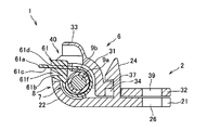
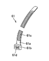
- FIG. 1 It is a perspective view showing a schematic structure of a wire harness provided with a fixture for wire harness concerning a first embodiment of the present invention. It is a cross-sectional view of the fixture for wire harnesses of the wire harness shown in FIG. It is a perspective view of the mark member of the fixing tool for wire harnesses shown in FIG. It is a perspective view which shows the state by which the holding part of the fixing tool for wire harnesses of the wire harness shown in FIG. 1 was closed. It is a perspective view which shows the state by which the holding part of the fixing tool for wire harnesses shown in FIG. 4 was open
- FIG. 1 It is a cross-sectional view of the fixture for wire harnesses of the wire harness shown in FIG.
- FIG. 1 It is a perspective view of the mark member of the fixing tool for wire harnesses shown in FIG.
- FIG. 4 shows the state by which
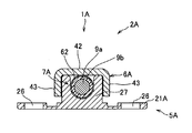
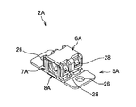
- FIG. 7 is a cross-sectional view taken along line II of the wire harness shown in FIG. 6. It is a figure which shows the state by which the holding part of the fixing tool for wire harnesses of the wire harness shown in FIG. 6 was closed. It is a front view of the fixing tool for wire harnesses shown in FIG. It is a figure which shows the 1st accommodating part of the fixing tool for wire harnesses shown in FIG. It is a figure which shows the 2nd accommodating part of the fixing tool for wire harnesses shown in FIG.
- the wire harness 1 having the wire harness fixture 2 according to the first embodiment of the present invention includes, as shown in FIG. 1, a plurality of electric wires 9, a connector 72 provided at the end of the electric wires 9, A protector 76 and a tube 77 for protecting the plurality of electric wires 9, a grommet 75 for protecting the plurality of electric wires 9 inserted through a through hole of a panel (not shown), and a wire harness for bundling the plurality of electric wires 9 A tape 78 and a wire harness fixture 2 for fixing the electric wire 9 to the panel are provided.
- the electric wire 9 includes a conductive core wire 9a and an insulating covering portion 9b.
- the core wire 9a is formed by twisting a plurality of conductive wires.
- the conducting wire is made of a conductive metal such as copper or a copper alloy.
- the covering portion is made of polyvinyl chloride resin or polyethylene resin, and is provided on the outer peripheral surface of the core wire to cover the core wire. For this reason, the outer surface of the electric wire 9 is the outer surface of the said coating
- the core wire 9a may be comprised from one conducting wire.
- the wire harness fixture 2 holds a binding band 61 as a mark member wound around the electric wire 9 as shown in FIG.
- the binding band 61 is provided with an engaging portion 61b at one end of the band-shaped portion 61a.
- the binding band 61 is formed of a synthetic resin such as a polypropylene resin.
- the band-shaped part 61a is provided with serrated projections 61c continuously in the longitudinal direction of the band-shaped part 61a.
- the engaging portion 61b has an insertion hole 61d provided with an engaging claw 61f that is inserted from one end of the belt-like portion 61a and engages with the serrated projection 61c.
- the binding band 61 binds the electric wires 9, and the extra length of the band-like portion 61a that is inserted through the insertion hole 61d and protrudes from the insertion hole 61d is cut in the vicinity of the engagement portion 61b.
- the wire harness fixture 2 includes a holding portion 7 for holding a binding band 61 as a mark member wound along the outer peripheral surface of the electric wire 9.
- the wire harness fixture 2 is provided with holes (shown in FIG. 2) 26 and 39 to which screw members and the like fastened to the panel are attached.
- the wire harness fixture 2 is integrally formed of a flexible synthetic resin such as polypropylene resin.
- the holding part 7 includes a first accommodation part 8 and a second accommodation part 6 as shown in FIGS. 2, 4 and 5.
- the first accommodating portion 8 has a plate-like portion 21 formed in a thin plate shape and a first portion formed in an arc shape along the outer shape of the electric wire 9 provided at one end portion of one surface of the plate-like portion 21.
- One arc-shaped portion 22 and an engaging protrusion 24 erected from one surface of the plate-shaped portion 21 are provided.
- the second accommodating portion 6 is connected to a flexible portion 38 provided at one end portion of the first arc-shaped portion 22 and has an arc shape along the outer shape of the electric wire 9.
- the formed second arcuate portion 31, the plate-like portion 32 formed extending from one end of the second arcuate portion 31, and the engagement protrusion 24 are inserted and the engagement protrusion 24 is engaged.
- Engaging holes 34 are provided.
- the plate-like portion 21 is provided with a hole portion 26 that is opened on the other end side of the plate-like portion 21 and penetrates the plate-like portion 21.
- the first arc-shaped portion 22 is formed in an arc shape along the outer shape of the electric wire 9 and press projections 23, 23 that press the outer surface of the electric wire 9, and the binding band
- the pressing protrusions 23 and 23 are juxtaposed in the axial direction of the electric wire 9 with an interval that does not interfere with the band-like portion 61 a and the engaging portion 61 b of the binding band 61.
- the pressing protrusions 23 and 23 are disposed to face the pressing protrusions 36 and 36 provided on the second arcuate portion 31.
- the flexible portion 38 is formed thinner than the first arc-shaped portion 22 and the second arc-shaped portion 31, and as shown in FIG. 7, the first arc-shaped portion 22 is formed. And the second arcuate portion 31 are formed to have a strength to keep the opened state. For this reason, the first accommodating portion 8 and the second accommodating portion 6 are rotatably connected by the flexible portion 38.
- the engaging protrusion 24 is formed with an inclined surface whose protruding amount increases from the distal end portion to the proximal end portion of the engaging protrusion 24.
- the engagement protrusion 24 is extended and extended to a substantially intermediate position of the flexible portion 38.
- the second arc-shaped portion 31 is formed in an arc shape along the flexible portions 38, 38 provided on both sides of the opening 40 and the outer peripheral surface of the electric wire 9.
- pressing protrusions 36 and 36 that press the outer surface of the electric wire 9, and a band-like portion 61a of the binding band 61 that communicates with the opening 40 and protrudes outside the second arcuate portion 31 and is exposed to the outside.
- a flange 33 that protects the engaging portion 61b.
- the pressing protrusions 36 and 36 are arranged in parallel in the axial direction of the electric wire 9 with an interval that does not interfere with the band-like portion 61 a and the engaging portion 61 b of the binding band 61.
- the pressing protrusions 36 and 36 are arranged to face the pressing protrusions 23 and 23 provided on the first arcuate portion 22.
- the opening 40 is formed by the band-like portion 61 a of the binding band 61, the engaging portion 61 b and the opening 40 interfering with each other, so that the wire harness fixture 2 is connected to the electric wire 9.
- the dimension is such that it does not move in the axial direction of the wire 9 and does not rotate in the circumferential direction of the outer peripheral surface of the electric wire 9.
- the position of the axial direction of the electric wire 9 and the position of the outer peripheral surface direction of the said electric wire 9 are prescribed
- an electric wire having a diameter larger than that of the illustrated electric wire 9 may be held by the holding unit 7.
- the flange 33 is formed to have the same width as the axial width of the electric wire 9 of the opening 40.
- the flange portion 33 protrudes with a protruding amount having a dimension in which the engaging portion 61b of the binding band 61 is accommodated.
- the engagement hole 34 is provided with a claw portion 37 that engages with a portion where the protruding amount of the inclined surface of the engagement protrusion 24 is maximum.
- the engagement hole 34 is formed to have a dimension through which the engagement protrusion 24 is inserted.
- the plate-like portion 32 is provided with a hole 39 that penetrates the plate-like portion 32.
- the hole 39 is provided at a position communicating with the hole 26 opened in the plate-like portion 21 in a state where the plate-like portion 32 and the plate-like portion 21 are closed.
- the holding portion 7 is formed in an arc shape along the outer peripheral surface of the electric wire 9 and is extended in the axial direction of the electric wire 9, and in an arc shape along the outer peripheral surface of the electric wire 9.
- the first arc-shaped portion 22 and the second arc-shaped portion 31 are formed in a cylindrical shape along the outer peripheral surface of the electric wire 9 with the plate-shaped portion 21 and the plate-shaped portion 32 being closed. Has been.
- the wire harness fixture 2 configured as described above is formed by injection molding or the like with the first housing portion 8 and the second housing portion 6 open as shown in FIG. Next, the binding band 61 is bound at an attachment position where the wire harness fixture 2 is attached to the wire harness 1, and the extra length of the band-like portion 61 a of the binding band 61 is cut and removed.
- the wire harness 1 is routed on a panel such as a vehicle body in a required routing form.
- the wire harness fixture 2 in the wire harness fixture 2, the first housing portion 8 and the second housing portion 6 are closed, and the electric wire 9 of the wire harness 1 and the binding band 61 are held by the holding portion. 7, the wire harness fixture 2 is fixed to the wire harness 1.
- the wire 9 held by the wire harness fixture 2 may be a wire bundle in which a plurality of wires 9 are bundled.
- the holes 26 and 39 of the wire harness fixture 2 fixed to the wire harness 1 are communicated with the mounting holes of the panel, and screw members or the like are inserted into the holes 26 and 39 and the mounting holes. And screwed together. Then, the wire harness 1 is fixed to the panel.
- the wire harness fixture 2 according to the first embodiment described above is used as a mark for attaching the wire harness fixture 2 to the electric wire 9 and is bound as a mark member wound along the outer peripheral surface of the electric wire 9.
- a holding part 7 for holding the band 61 is provided.
- the holding portion 7 includes a first accommodating portion 8 that accommodates the electric wire 9, and a second accommodating portion 6 that accommodates the electric wire 9 and faces the first accommodating portion 8.
- a flexible portion 38 is provided which is connected to the one accommodating portion 8 and the second accommodating portion 6 and which rotatably connects the first accommodating portion 8 and the second accommodating portion 6.
- the binding band 61 is wound along the outer peripheral surface of the electric wire 9 and is formed in a belt-like shape, and a member provided at one end of the belt-like portion 61a and engaged through the belt-like portion 61a.
- the holding part 7 of the wire harness fixture 2 is provided with an opening 40 that exposes the engaging part 61b of the binding band 61.
- the wire harness fixture 2 holds the binding band 61 wound along the outer peripheral surface of the electric wire 9 by the holding portion 7, the positional accuracy of the mounting position of the wire harness fixture 2 is high. improves.
- the wire harness fixture 2 is attached to the electric wire 9 without using a tool such as a bundling tool in order to hold the binding band 61 wound along the outer peripheral surface of the electric wire 9 by the holding portion 7. Can do. For this reason, after arranging the electric wire 9 in a narrow place where the wire harness fixture 2 is hooked, the wire harness fixture 2 can be attached to the electric wire 9 and the electric wire 9 can be fixed to the panel.
- a tool such as a bundling tool
- the wire harness fixture 2 holds the binding band 61 wound along the outer peripheral surface of the electric wire 9, it can be attached to the electric wires 9 having different wire diameters.
- the wire harness fixture 2 uses the binding band 61 wound along the outer peripheral surface of the wire 9 as a mark of the mounting position of the wire harness fixture 2, the wire 9 is routed on a panel or the like.
- the said wire harness fixing tool 2 can be attached to a required position later.
- the wire harness fixture 2 includes the first housing portion 8 and the second housing portion 6 that are engaged with each other and formed to be rotatable by the flexible portion 38, the outer peripheral surface of the electric wire 9 is provided. It is possible to easily hold the binding band 61 wound along the wire with a simple operation. For this reason, the work time of the attachment operation
- the wire harness fixture 2 is provided with an opening 40 that exposes the engaging portion 61 b of the binding band 61 wound along the outer peripheral surface of the electric wire 9.
- the engagement portion 61 b interferes with the peripheral portion of 40, and the wire harness fixture 2 is prevented from moving with respect to the electric wire 9. For this reason, the attaching position and the attaching direction of the wire harness fixture 2 can be defined by the binding band 61.
- the wire harness 1 includes the wire harness fixture 2 described above, the wire harness 1 is improved in position accuracy of the mounting position of the wire harness fixture 2.
- the wire harness fixture 2 is attached to the wire 9 to fix the wire 9 to the panel.
- the wire harness 1 can be obtained.
- the wire harness 1 becomes the wire harness 1 in which the attachment position and the attachment direction of the wire harness fixture 2 can be defined by the binding band 61.
- the wire harness manufacturing method attaches the wire harness fixture 2 to the binding band 61 of the electric wire 9 after routing the electric wire 9, the wire harness fixture 2 is not hooked at the time of routing. Work can be performed smoothly. Further, the wire harness fixture 2 can be easily attached to a required position of the electric wire 9.
- the binding band 61 is used as the mark member, the electric wires 9 are securely bound and the positioning is ensured.
- the bundling band 61 which is a general-purpose product can be used as the mark member, it can be used for the electric wires 9 having various wire diameters, and the versatility is improved and the wire harness 1 can be provided at a low cost. it can.
- the wire harness 1 ⁇ / b> A includes an electric wire 9, an adhesive tape 52 as a mark member wound around the electric wire 9, and a wire harness that holds the adhesive tape 52. 2A for fixtures.
- the adhesive tape 52 a general-purpose adhesive tape for electrical insulation, an adhesive sheet or the like is used.
- the adhesive tape 52 includes a film layer made of a synthetic resin and an adhesive layer that is provided on the film layer and can adhere to the electric wire 9.
- the film layer is mainly composed of a polyvinyl chloride resin, and is formed by blending a plasticizer, a flame retardant, and the like.
- the pressure-sensitive adhesive is mainly composed of rubber and is formed by blending a tackifier or a crosslinking agent.
- the adhesive tape 52 is wound around the outer peripheral surface of the electric wire 9 and binds the electric wire 9.
- the diameter of the portion where the adhesive tape 52 is wound around the electric wire 9 is formed such that the diameter is wound around the outer peripheral surface of the electric wire 9 and is held by the holding portion 7A of the wire harness fixture 2A described later. Yes.
- the wire harness fixture 2 ⁇ / b> A includes a holding portion 7 ⁇ / b> A that holds an adhesive tape 62 as a mark member wound along the outer peripheral surface of the electric wire 9.
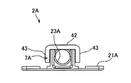
- the holding portion 7A includes a first accommodating portion 8A and a second accommodating portion 6A, and the second accommodating portion 6A and the first accommodating portion 8A are engaged with each other by an engaging means.
- the first accommodating portion 8A is provided with a plate-like portion 21A formed in a thin plate shape and a first groove 25 provided on one surface of the plate-like portion 21A. ing.
- the plate-like portion 21A is provided with holes 26 and 26 that are opened at both ends of the plate-like portion 21A. The holes 26 and 26 are opened to dimensions that allow a shaft of a screw member (not shown) to be inserted and dimensions that allow the head of the screw member to be locked.
- the first concave groove 25 is provided with wall portions 27, 27 that are provided upright from one surface of the plate-like portion 21 ⁇ / b> A, extend in the axial direction of the electric wire 9, and are parallel to each other.
- engaging claws 28, 28 as engaging means provided on the outer sides of the wall portions 27, 27, and a pressing force provided on the inner side of the wall portions 27, 27 to press the outer surface of the electric wire 9.
- Protrusions 23A, 23A, 23A, and a locking portion 12 standing on the other surface of the plate-like portion 21A are provided.
- the engaging claws 28 are provided with an interval in the axial direction of the electric wire 9 as shown in FIG.
- the engaging claws 28, 28 are formed with inclined surfaces whose protruding amounts increase downward from the upper ends of the wall portions 27, 27.
- the pressing protrusions 23 ⁇ / b> A, 23 ⁇ / b> A, 23 ⁇ / b> A are formed in a concave shape from the wall portions 27, 27 side toward the center side, and are formed in an arc shape along the outer shape of the electric wire 9. Yes.
- the pressing protrusions 23A, 23A, 23A are provided at equal intervals in the axial direction of the electric wire 9.
- the second housing portion 6 ⁇ / b> A is provided with a second concave groove 35 on the back surface.
- the second concave groove 35 includes a plate portion 42 that is overlapped with the upper ends of the wall portions 27 and 27 of the first concave groove 25, and extends downward from both ends of the plate portion 27.
- Wall portions 43, 43 adjacent to the outside, engagement holes 44, 44 as engagement means which are opened in the wall portions 43, 43 and engage with the engagement claws 28, 28, and the plate Pressing protrusions 36A and 36A that are provided inside the portion 42 and inside the wall portions 43 and 43 and press the outer surface of the electric wire 9.
- the engagement holes 44 and 44 are provided with openings having dimensions to allow the engagement claws 28 and 28 to be inserted therethrough.
- the engagement holes 44 are provided at intervals in the axial direction of the electric wire 9.
- the pressing protrusions 36A and 36A are formed in an arc shape along the outer shape of the electric wire 9, as shown in FIGS.
- the pressing protrusions 36A and 36A are provided with an interval in the axial direction of the electric wire 9, and the pressing protrusions 23A, 23A and 23A and the pressing protrusions 36A and 36A are alternately arranged with respect to the electric wire 9. It is provided at an interval for pressing the electric wire 9.
- the holding part 7A is composed of the first accommodating part 8A and the second accommodating part 6A, and the pressing protrusions 23A, 23A, 23A provided on the first accommodating part 8A side, and the second accommodating part 6A. And pressing protrusions 36A, 36A provided on the side.
- the wire harness fixture 2A configured as described above is formed by injection molding or the like, with the first housing portion 8A and the second housing portion 6A as separate bodies.
- the adhesive tape 62 is wound around the attachment position where the wire harness fixture 2A is attached to the wire harness 1A, and the electric wires 9 are bound.
- the wire harness 1A is routed on a panel such as a vehicle body in a required routing form.
- the wire harness fixture 2 ⁇ / b> A is closed at the first housing portion 8 and the second housing portion 6.
- the adhesive tape 62 wound around the electric wire 9 of the wire harness 1A is held by the holding portion 7 composed of the first concave groove 25 and the second concave groove 35, and the pressing protrusion of the holding portion 7A.
- the adhesive tape 62 is pressed by 23A, 23A, 23A and the pressing protrusions 36A, 36A, and the wire harness fixture 2A is fixed to the wire harness 1A.
- the wire 9 may be a wire bundle in which a plurality of wires 9 are bundled.
- the wire harness 1A to which the wire harness fixture 2A is fixed is fixed to the panel by screw members inserted into the holes 26 and 26.
- the wire harness fixture 2A according to the second embodiment described above is provided with the holding portion 7A for holding the adhesive tape 62 wound around the electric wire 9, use an attachment tool such as a bundling tool.
- the fixing tool 2A can be easily attached to the electric wire 9. For this reason, after the wire harness 1A is routed in a narrow place such as a panel, the wire harness fixture 2A can be attached to the electric wire 9. Therefore, when the wire harness 1A is routed to a panel or the like, the wire harness fixture 2A is prevented from being caught by the panel or the like.
- the wire harness fixture 2A holds the adhesive tape 62 wound around the wires 9 having different wire diameters by the holding portion 7A of the wire harness fixture 2A. Can be attached.
- the first receiving portion 8 and the second receiving portion 6 are provided with an engaging claw 28 and an engaging hole 44 as engaging means for engaging each other,
- said 1st accommodating part 8 and said 2nd accommodating part 6 are comprised by the different body, the structure of the cavity which shape
- first housing portion 8 and the second housing portion 6 when one of the first housing portion 8 and the second housing portion 6 is damaged, it can be used as the wire harness fixture 2 by exchanging the damaged one, thereby reducing the cost of component replacement. Can do.
- the wire harness fixture 2A holds the adhesive tape 62 wound around the electric wire 9
- the adhesive tape 62 can be used as a mark of the mounting position of the wire harness fixture 2A. For this reason, the work for adjusting the mounting position of the wire harness fixture 2A is facilitated, and the mounting accuracy is improved.
- the wire harness fixture 2A uses the adhesive tape 62 as a mark member, the positioning can be reliably performed and the diameter can be appropriately set according to the number of times of wrinkling. For this reason, the wire harness fixture 2 ⁇ / b> A can be attached to the electric wire 9 corresponding to the wire diameter of the electric wire 9. Further, since the number of times of winding the adhesive tape 62 can be adjusted so that the wire harness fixture 2A does not move in the axial direction of the electric wire 9 or rotate in the circumferential direction of the outer peripheral surface of the electric wire 9, Improves.
- the mark member can use a general-purpose adhesive tape 62, the wire harness 1A can be provided at low cost.
- the wire harness fixing device can be used as a fixing device for fixing the wire harness on a panel constituting the vehicle body of an automobile or the like, and the wire harness according to the present invention can be used for a vehicle body such as an automobile.
- the wiring harness wiring method according to the present invention can be used as a wire harness that can be fixed on a mounting hole provided in the panel while being routed on a panel that constitutes a vehicle body such as an automobile. It can be used as a wiring method for wiring the wire harness on the constituting panel and fixing the wire harness on the panel.
Landscapes
- Engineering & Computer Science (AREA)
- General Engineering & Computer Science (AREA)
- Mechanical Engineering (AREA)
- Architecture (AREA)
- Civil Engineering (AREA)
- Structural Engineering (AREA)
- Installation Of Indoor Wiring (AREA)
- Supports For Pipes And Cables (AREA)
- Clamps And Clips (AREA)
Abstract
【課題】配索後の電線に取り付けられ、前記電線の線径の大小に対応し、前記電線に安定して取り付けられるワイヤハーネス用固定具、および、該ワイヤハーネス用固定具を備えたワイヤハーネス、および、該ワイヤハーネスの配索方法を提供する。 【解決手段】ワイヤハーネス用固定具2は、当該ワイヤハーネス用固定具2を電線9に取り付ける目印とされ且つ当該電線9の外周面に沿って巻かれた目印部材61を抱持する抱持部7が設けられている。
Description
本発明は、配索後の電線に取り付けられ、前記電線の線径の大小に対応し、前記電線に安定して取り付けられるワイヤハーネス用固定具、および、該ワイヤハーネス用固定具を備えたワイヤハーネス、および、該ワイヤハーネスの配索方法に関する。
自動車等には、種々の電子機器と電装品とが搭載されている。これらの電子機器と電装品とにバッテリなどの電源等からの電力や制御装置等からの制御信号などを伝達する手段として、ワイヤハーネスが用いられている。
ワイヤハーネスは、自動車等の車体を構成するパネル上に配索されている。ワイヤハーネスには、前記パネルに開孔された取付孔に係止され前記ワイヤハーネスを当該パネルに固定する固定具が設けられている(例えば、特許文献1および特許文献2参照。)。
特許文献1に記載のワイヤハーネスは、当該ワイヤハーネスを構成する電線に前記固定具の取付位置を表示する目印テープが設けられ、前記目印テープ上に前記固定具の結束バンドが結束工具によって緊縛されている。
特許文献2に記載のワイヤハーネスは、当該ワイヤハーネスを構成する電線に、当該電線の軸方向に摺動可能に形成され前記固定具に嵌合される嵌合部材が設けられている。
しかしながら、特許文献1に記載のワイヤハーネスは、前記ワイヤハーネスが狭い箇所で配索された場合、結束口部によって固定具の帯状部を結束することが困難となるため、ワイヤハーネスの製造工程で前記固定具が取り付けられている。このため、ワイヤハーネスを配索した時に、前記固定具がパネル等に引っかかってしまい、円滑にワイヤハーネスの配索作業が行えないという問題があった。
また、特許文献1に記載のワイヤハーネスは、前述のように、ワイヤハーネスの製造工程で固定具が取り付けられているため、ワイヤハーネスの製造工程とは異なる工程や別の場所等で、ワイヤハーネスに固定具を取り付けることができないという問題があった。
特許文献2に記載のワイヤハーネスは、電線に設けられるスペーサと当該スペーサに嵌合される固定具とが一対として形成されているため、互いに専用品となっており、汎用性がないという問題があった。
また、特許文献2に記載のワイヤハーネスは、線径が大径の電線にスペーサを取り付けられないという問題があった。このため、電線の線径に応じて各種寸法のスペーサと固定具とを製造した場合、コストがかかるという問題があった。
また、特許文献2に記載のワイヤハーネスは、電線に対してスペーサが移動可能に形成されているため、スペーサを安定して位置決め状態に保持することができないという問題があった。
本発明は、かかる問題を解決することを目的としている。即ち、本発明は、配索後の電線に取り付けられ、前記電線の線径の大小に対応し、前記電線に安定して取り付けられるワイヤハーネス用固定具、および、該ワイヤハーネス用固定具を備えたワイヤハーネス、および、該ワイヤハーネスの配索方法を提供することを目的としている。
前記課題を解決し目的を達成するために、請求項1に記載された発明は、電線をパネルに固定するワイヤハーネス用固定具において、前記ワイヤハーネス用固定具には、当該ワイヤハーネス用固定具を前記電線に取り付ける目印とされ且つ当該電線の外周面に沿って巻かれた目印部材を抱持する抱持部が設けられていることを特徴とするワイヤハーネス用固定具である。
請求項2に記載された発明は、前記抱持部は、前記電線を収容する第一収容部と、前記電線を収容すると共に前記第一収容部に対向する第二収容部と、を備え、かつ、前記第一収容部と前記第二収容部とに連設され且つ当該第一収容部と当該第二収容部とを回動可能に連結した可撓部が設けられていることを特徴とする請求項1に記載のワイヤハーネス用固定具である。
請求項3に記載された発明は、前記抱持部は、前記電線を収容する第一収容部と、前記電線を収容すると共に前記第一収容部に対向する第二収容部と、を備え、前記第一収容部と前記第二収容部とには、互いに係合する係合手段が設けられ、かつ、前記第一収容部と前記第二収容部とが、別体で構成されていることを特徴とする請求項1に記載のワイヤハーネス用固定具である。
請求項4に記載された発明は、前記目印部材が、前記電線の外周面に沿って巻かれ且つ帯状に形成された帯状部と、前記帯状部の一端に設けられ且つ当該帯状部を挿通して係合する係合部と、を備え、前記ワイヤハーネス用固定具の前記抱持部には、前記目印部材の前記係合部を露出する開口部が設けられていることを特徴とする請求項1~請求項3のいずれか一項に記載のワイヤハーネス用固定具である。
請求項5に記載された発明は、パネルに配索される電線と、前記電線を前記パネルに固定するワイヤハーネス用固定具と、を備えたワイヤハーネスにおいて、前記ワイヤハーネス用固定具が、請求項1~請求項4のいずれか一項に記載のワイヤハーネス用固定具とされていることを特徴とするワイヤハーネスである。
請求項6に記載された発明は、請求項5に記載のワイヤハーネスを前記パネルに配索する配線方法であって、前記目印部材が外周面に沿って巻かれた前記電線を前記パネルに配索し、前記目印部材を前記ワイヤハーネス用固定具の抱持部で抱持し、前記ワイヤハーネス用固定具を前記パネルに固定することを特徴とするワイヤハーネスの配索方法である。
請求項1に記載された発明によれば、ワイヤハーネス用固定具は、電線の外周面に沿って巻かれた目印部材を抱持部で抱持するため、前記ワイヤハーネス用固定具の取付位置の位置精度が向上する。
また、ワイヤハーネス用固定具は、電線の外周面に沿って巻かれた目印部材を抱持部で抱持するため、結束工具などの工具を使用せずに電線に取り付けることができる。このため、ワイヤハーネス用固定具が引掛かるような狭い箇所に電線を配索した後に、前記ワイヤハーネス用固定具を電線に取り付けて当該電線をパネルに固定することができる。
また、ワイヤハーネス用固定具は、電線の外周面に沿って巻かれた目印部材を抱持するため、線径の異なる電線に取り付けることができる。このため、汎用性が向上する。
また、ワイヤハーネス用固定具は、電線の外周面に沿って巻かれた目印部材を前記ワイヤハーネス用固定具の取付位置の目印としているため、電線をパネル等に配索した後に所要の位置に前記ワイヤハーネス用固定具を取り付けることができる。
請求項2に記載された発明によれば、ワイヤハーネス用固定具は、互いに係合され且つ可撓部によって回動可能に形成された第一収容部と第二収容部とを備えているため、電線の外周面に沿って巻かれた目印部材を簡単な操作で容易に抱持することができる。このため、ワイヤハーネス用固定具を電線に取り付ける取付作業の作業時間を短縮することができる。
請求項3に記載された発明によれば、ワイヤハーネス用固定具は、互いに係合され且つ別体で構成された第一収容部と第二収容部とを備えているため、金型における前記ワイヤハーネス用固定具を成形するキャビティの構造が簡略化される。このため、金型の制作費が抑えられ、ワイヤハーネス用固定具の費用を抑えることができる。
また、第一収容部と第二収容部との一方が破損した場合に、この破損した一方を交換することでワイヤハーネス用固定具として使用できるため、部品交換にかかる費用を抑えることができる。
請求項4に記載された発明によれば、ワイヤハーネス用固定具は、電線の外周面に沿って巻かれた目印部材の係合部を露出する開口部が抱持部に設けられているため、前記開口部の周縁部に前記係合部が干渉し、前記ワイヤハーネス用固定具が前記電線に対して移動することを防止する。このため、前記ワイヤハーネス用固定具の取付位置と、取付方向とを前記目印部材によって規定することができる。
請求項5に記載された発明によれば、ワイヤハーネスは、請求項1~請求項4のいずれか一項に記載のワイヤハーネス用固定具を備えているため、前記ワイヤハーネス用固定具の取付位置の位置精度が向上したワイヤハーネスとなる。
また、ワイヤハーネスは、ワイヤハーネス用固定具が引掛かるような狭い箇所に電線を配索した後に、前記ワイヤハーネス用固定具を電線に取り付けて当該電線をパネルに固定することができるワイヤハーネスとなる。
また、ワイヤハーネスは、ワイヤハーネス用固定具の取付位置と、取付方向とを前記目印部材によって規定することができるワイヤハーネスとなる。
請求項6に記載された発明によれば、ワイヤハーネスの製造方法は、電線を配索した後に当該電線の目印部材にワイヤハーネス用固定具を取り付けるため、配索時にワイヤハーネス用固定具が引掛かることがなくなり、配索作業を円滑に行うことができる。また、所要の位置に前記ワイヤハーネス用固定具を容易に取り付けることができる。
以下、本発明の実施形態について、図1~図11を参照して説明する。
本発明の第一の実施形態にかかるワイヤハーネス用固定具2を有するワイヤハーネス1は、図1に示すように、複数本の電線9と、前記電線9の端末に設けられたコネクタ72と、前記複数本の電線9を保護するプロテクタ76とチューブ77と、図示しないパネルの貫通孔に挿通された前記複数本の電線9を保護するグロメット75と、前記複数本の電線9を束ねるワイヤハーネス用テープ78と、前記電線9を前記パネルに固定するワイヤハーネス用固定具2と、を備えている。
電線9は、図2に示すように、導電性の芯線9aと、絶縁性の被覆部9bとを備えている。芯線9aは、複数本の導線が撚られて形成されている。導線は、銅や銅合金等の導電性の金属からなる。被覆部は、ポリ塩化ビニル樹脂、あるいは、ポリエチレン樹脂などからなり、前記芯線の外周面に設けられ当該芯線を被覆している。このため、電線9の外表面は、前記被覆部9bの外表面となっている。なお、芯線9aは、一本の導線から構成されても良い。
ワイヤハーネス用固定具2は、図2に示すように、電線9に巻かれた目印部材としての結束バンド61を抱持している。結束バンド61は、図3に示すように、帯状部61aの一端に係合部61bが設けられている。結束バンド61は、ポリプロピレン樹脂などの合成樹脂によって形成されている。
帯状部61aには、図3に示すように、鋸歯状突起61cが前記帯状部61aの長手方向に連続して設けられている。係合部61bには、前記帯状部61aの一端部から挿通され前記鋸歯状突起61cに係合する係合爪61fが設けられた挿通孔61dが開孔されている。結束バンド61は、前記電線9を結束すると共に、前記挿通孔61dに挿通され当該挿通孔61dから突出した前記帯状部61aの余長が、前記係合部61bの近傍で切断されている。
ワイヤハーネス用固定具2は、電線9の外周面に沿って巻かれた目印部材としての結束バンド61を抱持する抱持部7を備えている。ワイヤハーネス用固定具2には、パネルに締結されるネジ部材等が取り付けられる孔部(図2に示す)26,39が設けられている。ワイヤハーネス用固定具2は、ポリプロピレン樹脂などの可撓性を有する合成樹脂で一体成形されている。
抱持部7は、図2、図4および図5に示すように、第一収容部8と、第二収容部6とを備えている。第一収容部8には、薄板状に形成された板状部21と、前記板状部21の一方の面の一端部に設けられ前記電線9の外形に沿って円弧状に形成された第一円弧状部22と、前記板状部21の一方の面から立設された係合突起24と、が設けられている。
第二収容部6には、図2および図4に示すように、前記第一円弧状部22の一端部に設けられた可撓部38に連結され前記電線9の外形に沿って円弧状に形成された第二円弧状部31と、前記第二円弧状部31の一端部から延長されて形成された板状部32と、前記係合突起24が挿通され当該係合突起24が係合される係合孔34と、が設けられている。
板状部21には、図2に示すように、前記板状部21の他端側に開孔され当該板状部21を貫通する孔部26が設けられている。
第一円弧状部22は、図2および図5に示すように、前記電線9の外形に沿って円弧状に形成され当該電線9の外表面を押圧する押圧突起23,23と、前記結束バンド61の帯状部61aと係合部61bとが露出される開口部40と、前記開口部40の両側に設けられ前記第二円弧状部31に連設された可撓部38,38と、を備えている。
押圧突起23,23は、図5に示すように、前記結束バンド61の帯状部61aと係合部61bとに干渉しない間隔を空けて、前記電線9の軸方向に並設されている。押圧突起23,23は、前記第二円弧状部31に設けられた押圧突起36,36に対向して配置されている。
可撓部38は、図4に示すように、前記第一円弧状部22と前記第二円弧状部31とよりも薄肉に形成され、図7に示すように、前記第一円弧状部22と前記第二円弧状部31とが開放された状態を保持する強度に形成されている。このため、可撓部38によって、前記第一収容部8と前記第二収容部6とが回動可能に連結されている。
係合突起24は、図2に示すように、前記係合突起24の先端部から基端部に向かって突出量が増加する傾斜面が形成されている。係合突起24は、前記可撓部38の略中間位置にまで延長して立設されている。
第二円弧状部31は、図2および図5に示すように、前記開口部40の両側に設けられた前記可撓部38,38と、前記電線9の外周面に沿って円弧状に形成され当該電線9の外表面を押圧する押圧突起36,36と、前記開口部40に連通され前記第二円弧状部31の外側に突設され外部に露出した前記結束バンド61の帯状部61aと係合部61bとを保護する庇部33と、を備えている。
押圧突起36,36は、図5に示すように、前記結束バンド61の帯状部61aと係合部61bとに干渉しない間隔を空けて、前記電線9の軸方向に並設されている。押圧突起36,36は、前記第一円弧状部22に設けられた押圧突起23,23に対向して配置されている。
開口部40は、図2および図5に示すように、前記結束バンド61の帯状部61aと係合部61bと前記開口部40とが干渉して、前記ワイヤハーネス用固定具2が前記電線9の軸方向に移動したり、前記電線9の外周面の周方向に回転したりしない寸法に形成されている。なお、開口部40によって電線9の軸方向の位置と、前記電線9の外周面方向の位置とが規定されるため、前記電線9を押圧する前記押圧突起23,23,36,36を設けずに、図示した前記電線9よりも大径の電線を抱持部7で抱持するようにしても良い。
庇部33は、図2および図5に示すように、前記開口部40の前記電線9の軸方向の幅と同一幅に形成されている。庇部33は、前記結束バンド61の係合部61bが収容される寸法の突出量で突設されている。
係合孔34は、図2および図5に示すように、前記係合突起24の前記傾斜面の突出量が最大となる部分に係合する爪部37が設けられている。係合孔34は、前記係合突起24が挿通される寸法に形成されている。
板状部32は、図2および図5に示すように、前記板状部32を貫通する孔部39が設けられている。孔部39は、前記板状部32と前記板状部21とが閉止した状態で、当該板状部21に開孔された孔部26に連通する位置に設けられている。
抱持部7は、前記電線9の外周面に沿って円弧状に形成され当該電線9の軸方向に延長された第一円弧状部22と、前記電線9の外周面に沿って円弧状に形成され当該電線9の軸方向に延長された第二円弧状部31と、前記第一円弧状部22と前記第二円弧状部31とに連通され前記結束バンド61の帯状部61aと係合部61bとを外部に露出させる開口部40と、前記開口部40に連通され前記第二円弧状部31に設けられ前記帯状部61aと係合部61bとを保護する庇部33と、前記第一円弧状部22の内周面に設けられ前記電線9の外周面に沿って円弧状に形成され当該電線9の外表面を押圧する押圧突起23,23と、前記第二円弧状部31の内周面に設けられ前記電線9の外周面に沿って円弧状に形成され当該電線9の外表面を押圧する押圧突起36,36と、を備えている。前記第一円弧状部22と前記第二円弧状部31とは、前記板状部21と前記板状部32とが閉止された状態で、前記電線9の外周面に沿った円筒状に形成されている。
上述の如く構成されたワイヤハーネス用固定具2は、図5に示すように、第一収容部8と第二収容部6とが開放された形態で、射出成形等によって形成される。次いで、前記ワイヤハーネス用固定具2が前記ワイヤハーネス1に取り付けられる取付位置に、前記結束バンド61が結束され、当該結束バンド61の帯状部61aの余長が切断され取り除かれる。
次いで、前記ワイヤハーネス1が車体等のパネルに所要の配索形態で配索される。次いで、ワイヤハーネス用固定具2は、図4に示すように、第一収容部8と第二収容部6とが閉止され、前記ワイヤハーネス1の電線9と前記結束バンド61とが抱持部7に抱持され、前記ワイヤハーネス用固定具2が前記ワイヤハーネス1に固定される。なお、前記ワイヤハーネス用固定具2に抱持される電線9は、複数本の電線9が束ねられた電線束でも良い。
次いで、前記ワイヤハーネス1に固定された前記ワイヤハーネス用固定具2の孔部26,39とパネルの取付孔とを連通させ、前記孔部26,39と前記取付孔とにネジ部材等が挿通されて螺合される。そして、前記ワイヤハーネス1が前記パネルに固定される。
上述の第一の実施形態にかかるワイヤハーネス用固定具2は、当該ワイヤハーネス用固定具2を電線9に取り付ける目印とされ且つ当該電線9の外周面に沿って巻かれた目印部材としての結束バンド61を抱持する抱持部7が設けられている。
前記抱持部7は、前記電線9を収容する第一収容部8と、前記電線9を収容すると共に前記第一収容部8に対向する第二収容部6と、を備え、かつ、前記第一収容部8と前記第二収容部6とに連設され且つ当該第一収容部8と当該第二収容部6とを回動可能に連結した可撓部38が設けられている。
前記結束バンド61が、前記電線9の外周面に沿って巻かれ且つ帯状に形成された帯状部61aと、前記帯状部61aの一端に設けられ且つ当該帯状部61aを挿通して係合する係合部61bと、を備え、前記ワイヤハーネス用固定具2の前記抱持部7には、前記結束バンド61の前記係合部61bを露出する開口部40が設けられている。
このため、ワイヤハーネス用固定具2は、電線9の外周面に沿って巻かれた結束バンド61を抱持部7で抱持するため、前記ワイヤハーネス用固定具2の取付位置の位置精度が向上する。
また、ワイヤハーネス用固定具2は、電線9の外周面に沿って巻かれた結束バンド61を抱持部7で抱持するため、結束工具などの工具を使用せずに電線9に取り付けることができる。このため、ワイヤハーネス用固定具2が引掛かるような狭い箇所に電線9を配索した後に、前記ワイヤハーネス用固定具2を電線9に取り付けて当該電線9をパネルに固定することができる。
また、ワイヤハーネス用固定具2は、電線9の外周面に沿って巻かれた結束バンド61を抱持するため、線径の異なる電線9に取り付けることができる。
また、ワイヤハーネス用固定具2は、電線9の外周面に沿って巻かれた結束バンド61を前記ワイヤハーネス用固定具2の取付位置の目印としているため、電線9をパネル等に配索した後に所要の位置に前記ワイヤハーネス用固定具2を取り付けることができる。
また、ワイヤハーネス用固定具2は、互いに係合され且つ可撓部38によって回動可能に形成された第一収容部8と第二収容部6とを備えているため、電線9の外周面に沿って巻かれた結束バンド61を簡単な操作で容易に抱持することができる。このため、ワイヤハーネス用固定具2を電線9に取り付ける取付作業の作業時間を短縮することができる。
また、ワイヤハーネス用固定具2は、電線9の外周面に沿って巻かれた結束バンド61の係合部61bを露出する開口部40が抱持部7に設けられているため、前記開口部40の周縁部に前記係合部61bが干渉し、前記ワイヤハーネス用固定具2が前記電線9に対して移動することを防止する。このため、前記ワイヤハーネス用固定具2の取付位置と、取付方向とを前記結束バンド61によって規定することができる。
ワイヤハーネス1は、前述したワイヤハーネス用固定具2を備えているため、前記ワイヤハーネス用固定具2の取付位置の位置精度が向上したワイヤハーネス1となる。
また、ワイヤハーネス1は、ワイヤハーネス用固定具2が引掛かるような狭い箇所に電線9を配索した後に、前記ワイヤハーネス用固定具2を電線9に取り付けて当該電線9をパネルに固定することができるワイヤハーネス1となる。
また、ワイヤハーネス1は、ワイヤハーネス用固定具2の取付位置と、取付方向とを前記結束バンド61によって規定することができるワイヤハーネス1となる。
ワイヤハーネスの製造方法は、電線9を配索した後に当該電線9の結束バンド61にワイヤハーネス用固定具2を取り付けるため、配索時にワイヤハーネス用固定具2が引掛かることがなくなり、配索作業を円滑に行うことができる。また、電線9の所要の位置に前記ワイヤハーネス用固定具2を容易に取り付けることができる。
また、目印部材として結束バンド61が使用されるため、電線9が確実に結束され、位置決めが確実となる。
また、目印部材は、汎用品である結束バンド61を使用することができるため、各種線径の電線9に使用することができ、汎用性が向上すると共にワイヤハーネス1を安価に提供することができる。
(第二の実施形態)
次に、本発明にかかるワイヤハーネス用固定具2Aを備えたワイヤハーネス1Aの第二の実施形態について、図6~図11を参照して説明する。なお、前述した実施形態と同一部分には、同一の符号を付して説明を省略する。
次に、本発明にかかるワイヤハーネス用固定具2Aを備えたワイヤハーネス1Aの第二の実施形態について、図6~図11を参照して説明する。なお、前述した実施形態と同一部分には、同一の符号を付して説明を省略する。
本実施形態にかかるワイヤハーネス1Aは、図6および図7に示すように、電線9と、前記電線9に巻かれた目印部材としての粘着テープ52と、前記粘着テープ52を抱持したワイヤハーネス用固定具2Aと、を備えている。
粘着テープ52は、汎用品としての電気絶縁用粘着テープ、粘着シート等が使用される。粘着テープ52は、合成樹脂からなるフィルム層と、前記フィルム層上に設けられ前記電線9に粘着可能な粘着剤層と、を備えている。フィルム層は、ポリ塩化ビニル樹脂を主成分とし、可塑剤や難燃剤等が配合され形成されている。粘着剤は、ゴムを主成分とし、粘着付与剤や架橋剤等が配合され形成されている。粘着テープ52は、前記電線9の外周面に捲回され当該電線9を結束している。粘着テープ52が前記電線9に捲回された部分の直径は、前記電線9の外周面に捲回され後述するワイヤハーネス用固定具2Aの抱持部7Aに抱持される直径に形成されている。
ワイヤハーネス用固定具2Aは、図6に示すように、電線9の外周面に沿って巻かれた目印部材としての粘着テープ62を抱持する抱持部7Aを備えている。抱持部7Aは、第一収容部8Aと第二収容部6Aとを備え、前記第二収容部6Aと前記第一収容部8Aとが係合手段によって互いに係合している。
第一収容部8Aは、図7~図10に示すように、薄板状に形成された板状部21Aと、前記板状部21Aの一方の面に設けられた第一凹溝25が設けられている。板状部21Aには、図14、図21および図22に示すように、前記板状部21Aの両端部にそれぞれ開孔された孔部26,26が設けられている。孔部26,26は、図示しないネジ部材の軸が挿通される寸法かつ当該ネジ部材の頭部が係止される寸法に開孔されている。
第一凹溝25は、図8および図10に示すように、前記板状部21Aの一方の面から立設され前記電線9の軸方向に延長され互いに平行に設けられた壁部27,27と、前記壁部27,27のそれぞれの外側に設けられた係合手段としての係合爪28,28と、前記壁部27,27の内側に設けられ前記電線9の外表面を押圧する押圧突起23A,23A,23Aと、前記板状部21Aの他方の面に立設された係止部12と、を備えている。
係合爪28,28は、図8に示すように、前記電線9の軸方向に間隔を空けて設けられている。係合爪28,28は、前記壁部27,27の上端部から下方に向かって突出量が増加する傾斜面が形成されている。
押圧突起23A,23A,23Aは、図9および図10に示すように、前記壁部27,27側から中央側に向かって凹状に形成され前記電線9の外形に沿って円弧状に形成されている。押圧突起23A,23A,23Aは、前記電線9の軸方向に等間隔に設けられている。
第二収容部6Aは、図9および図11に示すように、裏面に第二凹溝35が設けられている。第二凹溝35は、前記第一凹溝25の壁部27,27の上端部に重ねられる板部42と、前記板部27の両端部からそれぞれ下方に延長され前記壁部27,27の外側に隣接する壁部43,43と、前記壁部43,43のそれぞれに開孔され前記係合爪28,28が係合される係合手段としての係合孔44,44と、前記板部42の内側かつ前記壁部43,43の内側に設けられ前記電線9の外表面を押圧する押圧突起36A,36Aと、を備えている。
係合孔44,44は、図8および図11に示すように、前記係合爪28,28が挿通する寸法の開口が設けられている。係合孔44,44は、前記電線9の軸方向に間隔を空けて設けられている。
押圧突起36A,36Aは、図9および図11に示すように、前記電線9の外形に沿って円弧状に形成されている。押圧突起36A,36Aは、前記電線9の軸方向に間隔を空けて設けられていると共に、前記電線9に対して前記押圧突起23A,23A,23Aと前記押圧突起36A,36Aとが交互に当該電線9を押圧する間隔に設けられている。
抱持部7Aは、前記第一収容部8Aと前記第二収容部6Aとから構成され、前記第一収容部8A側に設けられた押圧突起23A,23A,23Aと、前記第二収容部6A側に設けられた押圧突起36A,36Aと、を備えている。
上述の如く構成されたワイヤハーネス用固定具2Aは、図10および図11に示すように、第一収容部8Aと第二収容部6Aとが別体として、射出成形等によって形成される。次いで、前記ワイヤハーネス用固定具2Aが前記ワイヤハーネス1Aに取り付けられる取付位置に、前記粘着テープ62が捲回され前記電線9が結束される。
次いで、前記ワイヤハーネス1Aが車体等のパネルに所要の配索形態で配索される。次いで、ワイヤハーネス用固定具2Aは、図6に示すように、第一収容部8と第二収容部6とが閉止される。このとき、前記ワイヤハーネス1Aの電線9に捲回された粘着テープ62が第一凹溝25と第二凹溝35とからなる抱持部7に抱持され、前記抱持部7Aの押圧突起23A,23A,23Aと押圧突起36A,36Aとによって前記粘着テープ62が押圧され、前記ワイヤハーネス1Aに前記ワイヤハーネス用固定具2Aが固定される。なお、前記電線9は、複数本の電線9が束ねられた電線束でも良い。
そして、前記ワイヤハーネス用固定具2Aが固定された前記ワイヤハーネス1Aが、孔部26,26に挿入したネジ部材によってパネルに固定される。
上述の第二の実施形態にかかるワイヤハーネス用固定具2Aは、電線9に巻かれた粘着テープ62を抱持する抱持部7Aが設けられているため、結束工具などの取付工具を使用せずに前記電線9に前記固定具2Aを容易に取り付けられる。このため、前記ワイヤハーネス1Aがパネル等の狭い箇所に配索された後に、前記電線9に前記ワイヤハーネス用固定具2Aを取り付けることができる。従って、前記ワイヤハーネス1Aをパネル等に配索する際に前記ワイヤハーネス用固定具2Aが当該パネル等に引っかかることが防止される。
また、ワイヤハーネス用固定具2Aは、線径の異なる電線9に巻かれた前記粘着テープ62を当該ワイヤハーネス用固定具2Aの抱持部7Aで抱持するため、線径の異なる電線9に取り付けることができる。
また、ワイヤハーネス用固定具2Aは、前記第一収容部8と前記第二収容部6とには、互いに係合する係合手段としての係合爪28と係合孔44とが設けられ、かつ、前記第一収容部8と前記第二収容部6とが、別体で構成されているため、金型における前記ワイヤハーネス用固定具2を成形するキャビティの構造が簡略化される。このため、金型の制作費が抑えられ、ワイヤハーネス用固定具2の費用とワイヤハーネス1の費用とを抑えることができる。
また、第一収容部8と第二収容部6との一方が破損した場合に、この破損した一方を交換することでワイヤハーネス用固定具2として使用できるため、部品交換にかかる費用を抑えることができる。
また、ワイヤハーネス用固定具2Aは、電線9に巻かれた粘着テープ62を抱持するため、前記ワイヤハーネス用固定具2Aの取付位置の目印として前記粘着テープ62を使用できる。このため、ワイヤハーネス用固定具2Aの取付位置の調整作業が容易となる上に、取付精度が向上する。
また、ワイヤハーネス用固定具2Aは、目印部材として粘着テープ62が使用されるため、位置決めが確実な上に、捲回数に応じて直径を適宜設定できる。このため、電線9の線径の大小に対応してワイヤハーネス用固定具2Aを当該電線9に取り付けることができる。また、ワイヤハーネス用固定具2Aが前記電線9の軸方向に移動したり、前記電線9の外周面の周方向に回転したりしない程度に前記粘着テープ62を巻き付ける捲回数が調整できるため、汎用性が向上する。
また、目印部材は、汎用品である粘着テープ62を使用することができるため、ワイヤハーネス1Aを安価に提供することができる。
なお、前述した実施形態は本発明の代表的な形態を示したに過ぎず、本発明は、実施形態に限定されるものではない。即ち、本発明の骨子を逸脱しない範囲で種々変形して実施することができる。
本発明にかかるワイヤハーネス用固定具は、自動車等の車体を構成するパネル上にワイヤハーネスを固定するための固定具として利用することができ、本発明にかかるワイヤハーネスは、自動車等の車体を構成するパネル上に配索されるとともに前記パネルに設けられた取付孔に固定することができるワイヤハーネスとして利用することができ、本発明にかかるワイヤハーネスの配索方法は、自動車等の車体を構成するパネル上にワイヤハーネスを配索するとともに当該パネル上に前記ワイヤハーネスを固定する配索方法として利用することができる。
1,1A ワイヤハーネス
2,2A ワイヤハーネス用固定具
6,6A 第二収容部
7,7A 抱持部
8,8A 第一収容部
9 電線
28 係合爪(係合手段)
44 係合孔(係合手段)
38 可撓部
40 開口部
61 結束バンド(目印部材)
61a 帯状部
61b 係合部
62 粘着テープ(目印部材)
2,2A ワイヤハーネス用固定具
6,6A 第二収容部
7,7A 抱持部
8,8A 第一収容部
9 電線
28 係合爪(係合手段)
44 係合孔(係合手段)
38 可撓部
40 開口部
61 結束バンド(目印部材)
61a 帯状部
61b 係合部
62 粘着テープ(目印部材)
Claims (6)
- 電線をパネルに固定するワイヤハーネス用固定具において、
前記ワイヤハーネス用固定具には、当該ワイヤハーネス用固定具を前記電線に取り付ける目印とされ且つ当該電線の外周面に沿って巻かれた目印部材を抱持する抱持部が設けられていることを特徴とするワイヤハーネス用固定具。 - 前記抱持部は、前記電線を収容する第一収容部と、前記電線を収容すると共に前記第一収容部に対向する第二収容部と、を備え、かつ、
前記第一収容部と前記第二収容部とに連設され且つ当該第一収容部と当該第二収容部とを回動可能に連結した可撓部が設けられていることを特徴とする請求項1に記載のワイヤハーネス用固定具。 - 前記抱持部は、前記電線を収容する第一収容部と、前記電線を収容すると共に前記第一収容部に対向する第二収容部と、を備え、
前記第一収容部と前記第二収容部とには、互いに係合する係合手段が設けられ、かつ、
前記第一収容部と前記第二収容部とが、別体で構成されていることを特徴とする請求項1に記載のワイヤハーネス用固定具。 - 前記目印部材が、前記電線の外周面に沿って巻かれ且つ帯状に形成された帯状部と、前記帯状部の一端に設けられ且つ当該帯状部を挿通して係合する係合部と、を備え、
前記ワイヤハーネス用固定具の前記抱持部には、前記目印部材の前記係合部を露出する開口部が設けられていることを特徴とする請求項1~請求項3のいずれか一項に記載のワイヤハーネス用固定具。 - パネルに配索される電線と、前記電線を前記パネルに固定するワイヤハーネス用固定具と、を備えたワイヤハーネスにおいて、
前記ワイヤハーネス用固定具が、請求項1~請求項4のいずれか一項に記載のワイヤハーネス用固定具とされていることを特徴とするワイヤハーネス。 - 請求項5に記載のワイヤハーネスを前記パネルに配索する配線方法であって、
前記目印部材が外周面に沿って巻かれた前記電線を前記パネルに配索し、前記目印部材を前記ワイヤハーネス用固定具の抱持部で抱持し、前記ワイヤハーネス用固定具を前記パネルに固定することを特徴とするワイヤハーネスの配索方法。
Applications Claiming Priority (2)
| Application Number | Priority Date | Filing Date | Title |
|---|---|---|---|
| JP2011-084526 | 2011-04-06 | ||
| JP2011084526A JP2012222901A (ja) | 2011-04-06 | 2011-04-06 | ワイヤハーネス用固定具、ワイヤハーネス、ワイヤハーネスの配索方法 |
Publications (1)
| Publication Number | Publication Date |
|---|---|
| WO2012137798A1 true WO2012137798A1 (ja) | 2012-10-11 |
Family
ID=46969192
Family Applications (1)
| Application Number | Title | Priority Date | Filing Date |
|---|---|---|---|
| PCT/JP2012/059142 Ceased WO2012137798A1 (ja) | 2011-04-06 | 2012-04-04 | ワイヤハーネス用固定具、ワイヤハーネス、ワイヤハーネスの配索方法 |
Country Status (2)
| Country | Link |
|---|---|
| JP (1) | JP2012222901A (ja) |
| WO (1) | WO2012137798A1 (ja) |
Families Citing this family (1)
| Publication number | Priority date | Publication date | Assignee | Title |
|---|---|---|---|---|
| JP6870691B2 (ja) * | 2019-01-28 | 2021-05-12 | コベルコ建機株式会社 | 作業機械 |
Citations (3)
| Publication number | Priority date | Publication date | Assignee | Title |
|---|---|---|---|---|
| JPH02118418U (ja) * | 1989-03-03 | 1990-09-21 | ||
| JPH05284626A (ja) * | 1992-02-13 | 1993-10-29 | A Raymond & Co | ケーブル束を収容するためのケーブルダクト |
| JP2009055726A (ja) * | 2007-08-28 | 2009-03-12 | Yazaki Corp | 線状物の固定構造 |
-
2011
- 2011-04-06 JP JP2011084526A patent/JP2012222901A/ja not_active Withdrawn
-
2012
- 2012-04-04 WO PCT/JP2012/059142 patent/WO2012137798A1/ja not_active Ceased
Patent Citations (3)
| Publication number | Priority date | Publication date | Assignee | Title |
|---|---|---|---|---|
| JPH02118418U (ja) * | 1989-03-03 | 1990-09-21 | ||
| JPH05284626A (ja) * | 1992-02-13 | 1993-10-29 | A Raymond & Co | ケーブル束を収容するためのケーブルダクト |
| JP2009055726A (ja) * | 2007-08-28 | 2009-03-12 | Yazaki Corp | 線状物の固定構造 |
Also Published As
| Publication number | Publication date |
|---|---|
| JP2012222901A (ja) | 2012-11-12 |
Similar Documents
| Publication | Publication Date | Title |
|---|---|---|
| US12249815B2 (en) | Wiring body with assembly assisting component, assembly assisting component of wiring body, and method of manufacturing wiring body assembly | |
| WO2010010883A1 (ja) | コネクタ | |
| JP5668617B2 (ja) | 経路維持部材付コルゲートチューブ及びワイヤーハーネス | |
| WO2015093613A1 (ja) | 保護チューブ及び保護チューブの取付方法 | |
| WO2009125524A1 (ja) | ワイヤハーネス | |
| JP5950793B2 (ja) | ワイヤハーネス | |
| JP2017103994A (ja) | ワイヤハーネス固定具およびそれを用いたワイヤハーネスの固定構造 | |
| CN104245429A (zh) | 线束 | |
| JP2015061463A (ja) | ワイヤハーネス用の結束具 | |
| JP2014180147A (ja) | 固定部材およびワイヤハーネス | |
| JP2012222901A (ja) | ワイヤハーネス用固定具、ワイヤハーネス、ワイヤハーネスの配索方法 | |
| JP5221081B2 (ja) | 線状物の固定構造 | |
| US20170004903A1 (en) | Wire harness having fixing member | |
| JP6295075B2 (ja) | 保護チューブの取付方法 | |
| JP2010130812A (ja) | テープ | |
| JPH1137349A (ja) | ワイヤハーネスの保護チューブ取付構造 | |
| JP6117405B2 (ja) | ワイヤハーネス | |
| KR200347448Y1 (ko) | 와이어 하네스 고정용 밴드케이블 구조 | |
| US8569624B2 (en) | Conducting path | |
| JP5892578B2 (ja) | ワイヤハーネス | |
| JP2015186284A (ja) | 固定具、ワイヤーハーネスユニット、およびワイヤーハーネスユニットの製造方法 | |
| CN220884284U (zh) | 一种新型固定件 | |
| JP3541728B2 (ja) | 粘着テープ一時保持具 | |
| JP2005347047A (ja) | ワイヤハーネス | |
| KR200391734Y1 (ko) | 자동차용 클리어런스 클립 조립구조 |
Legal Events
| Date | Code | Title | Description |
|---|---|---|---|
| 121 | Ep: the epo has been informed by wipo that ep was designated in this application |
Ref document number: 12767616 Country of ref document: EP Kind code of ref document: A1 |
|
| NENP | Non-entry into the national phase |
Ref country code: DE |
|
| 122 | Ep: pct application non-entry in european phase |
Ref document number: 12767616 Country of ref document: EP Kind code of ref document: A1 |