WO2012137535A1 - Particules précurseurs de matériau actif de cathode, particules précurseurs de matériau actif de cathode pour batterie secondaire au lithium et batterie secondaire au lithium - Google Patents
Particules précurseurs de matériau actif de cathode, particules précurseurs de matériau actif de cathode pour batterie secondaire au lithium et batterie secondaire au lithium Download PDFInfo
- Publication number
- WO2012137535A1 WO2012137535A1 PCT/JP2012/052719 JP2012052719W WO2012137535A1 WO 2012137535 A1 WO2012137535 A1 WO 2012137535A1 JP 2012052719 W JP2012052719 W JP 2012052719W WO 2012137535 A1 WO2012137535 A1 WO 2012137535A1
- Authority
- WO
- WIPO (PCT)
- Prior art keywords
- active material
- positive electrode
- electrode active
- particles
- lithium
- Prior art date
Links
Images


Classifications
-
- H—ELECTRICITY
- H01—ELECTRIC ELEMENTS
- H01M—PROCESSES OR MEANS, e.g. BATTERIES, FOR THE DIRECT CONVERSION OF CHEMICAL ENERGY INTO ELECTRICAL ENERGY
- H01M4/00—Electrodes
- H01M4/02—Electrodes composed of, or comprising, active material
- H01M4/36—Selection of substances as active materials, active masses, active liquids
- H01M4/48—Selection of substances as active materials, active masses, active liquids of inorganic oxides or hydroxides
- H01M4/52—Selection of substances as active materials, active masses, active liquids of inorganic oxides or hydroxides of nickel, cobalt or iron
- H01M4/525—Selection of substances as active materials, active masses, active liquids of inorganic oxides or hydroxides of nickel, cobalt or iron of mixed oxides or hydroxides containing iron, cobalt or nickel for inserting or intercalating light metals, e.g. LiNiO2, LiCoO2 or LiCoOxFy
-
- C—CHEMISTRY; METALLURGY
- C01—INORGANIC CHEMISTRY
- C01G—COMPOUNDS CONTAINING METALS NOT COVERED BY SUBCLASSES C01D OR C01F
- C01G51/00—Compounds of cobalt
- C01G51/40—Cobaltates
- C01G51/42—Cobaltates containing alkali metals, e.g. LiCoO2
-
- C—CHEMISTRY; METALLURGY
- C01—INORGANIC CHEMISTRY
- C01G—COMPOUNDS CONTAINING METALS NOT COVERED BY SUBCLASSES C01D OR C01F
- C01G53/00—Compounds of nickel
- C01G53/40—Nickelates
- C01G53/42—Nickelates containing alkali metals, e.g. LiNiO2
-
- C—CHEMISTRY; METALLURGY
- C01—INORGANIC CHEMISTRY
- C01P—INDEXING SCHEME RELATING TO STRUCTURAL AND PHYSICAL ASPECTS OF SOLID INORGANIC COMPOUNDS
- C01P2002/00—Crystal-structural characteristics
- C01P2002/50—Solid solutions
- C01P2002/52—Solid solutions containing elements as dopants
-
- C—CHEMISTRY; METALLURGY
- C01—INORGANIC CHEMISTRY
- C01P—INDEXING SCHEME RELATING TO STRUCTURAL AND PHYSICAL ASPECTS OF SOLID INORGANIC COMPOUNDS
- C01P2004/00—Particle morphology
- C01P2004/01—Particle morphology depicted by an image
- C01P2004/03—Particle morphology depicted by an image obtained by SEM
-
- C—CHEMISTRY; METALLURGY
- C01—INORGANIC CHEMISTRY
- C01P—INDEXING SCHEME RELATING TO STRUCTURAL AND PHYSICAL ASPECTS OF SOLID INORGANIC COMPOUNDS
- C01P2004/00—Particle morphology
- C01P2004/54—Particles characterised by their aspect ratio, i.e. the ratio of sizes in the longest to the shortest dimension
-
- C—CHEMISTRY; METALLURGY
- C01—INORGANIC CHEMISTRY
- C01P—INDEXING SCHEME RELATING TO STRUCTURAL AND PHYSICAL ASPECTS OF SOLID INORGANIC COMPOUNDS
- C01P2004/00—Particle morphology
- C01P2004/60—Particles characterised by their size
- C01P2004/62—Submicrometer sized, i.e. from 0.1-1 micrometer
-
- C—CHEMISTRY; METALLURGY
- C01—INORGANIC CHEMISTRY
- C01P—INDEXING SCHEME RELATING TO STRUCTURAL AND PHYSICAL ASPECTS OF SOLID INORGANIC COMPOUNDS
- C01P2006/00—Physical properties of inorganic compounds
- C01P2006/40—Electric properties
-
- H—ELECTRICITY
- H01—ELECTRIC ELEMENTS
- H01M—PROCESSES OR MEANS, e.g. BATTERIES, FOR THE DIRECT CONVERSION OF CHEMICAL ENERGY INTO ELECTRICAL ENERGY
- H01M10/00—Secondary cells; Manufacture thereof
- H01M10/05—Accumulators with non-aqueous electrolyte
- H01M10/052—Li-accumulators
-
- H—ELECTRICITY
- H01—ELECTRIC ELEMENTS
- H01M—PROCESSES OR MEANS, e.g. BATTERIES, FOR THE DIRECT CONVERSION OF CHEMICAL ENERGY INTO ELECTRICAL ENERGY
- H01M4/00—Electrodes
- H01M4/02—Electrodes composed of, or comprising, active material
- H01M2004/021—Physical characteristics, e.g. porosity, surface area
-
- H—ELECTRICITY
- H01—ELECTRIC ELEMENTS
- H01M—PROCESSES OR MEANS, e.g. BATTERIES, FOR THE DIRECT CONVERSION OF CHEMICAL ENERGY INTO ELECTRICAL ENERGY
- H01M4/00—Electrodes
- H01M4/02—Electrodes composed of, or comprising, active material
- H01M4/13—Electrodes for accumulators with non-aqueous electrolyte, e.g. for lithium-accumulators; Processes of manufacture thereof
- H01M4/131—Electrodes based on mixed oxides or hydroxides, or on mixtures of oxides or hydroxides, e.g. LiCoOx
-
- Y—GENERAL TAGGING OF NEW TECHNOLOGICAL DEVELOPMENTS; GENERAL TAGGING OF CROSS-SECTIONAL TECHNOLOGIES SPANNING OVER SEVERAL SECTIONS OF THE IPC; TECHNICAL SUBJECTS COVERED BY FORMER USPC CROSS-REFERENCE ART COLLECTIONS [XRACs] AND DIGESTS
- Y02—TECHNOLOGIES OR APPLICATIONS FOR MITIGATION OR ADAPTATION AGAINST CLIMATE CHANGE
- Y02E—REDUCTION OF GREENHOUSE GAS [GHG] EMISSIONS, RELATED TO ENERGY GENERATION, TRANSMISSION OR DISTRIBUTION
- Y02E60/00—Enabling technologies; Technologies with a potential or indirect contribution to GHG emissions mitigation
- Y02E60/10—Energy storage using batteries
-
- Y—GENERAL TAGGING OF NEW TECHNOLOGICAL DEVELOPMENTS; GENERAL TAGGING OF CROSS-SECTIONAL TECHNOLOGIES SPANNING OVER SEVERAL SECTIONS OF THE IPC; TECHNICAL SUBJECTS COVERED BY FORMER USPC CROSS-REFERENCE ART COLLECTIONS [XRACs] AND DIGESTS
- Y10—TECHNICAL SUBJECTS COVERED BY FORMER USPC
- Y10T—TECHNICAL SUBJECTS COVERED BY FORMER US CLASSIFICATION
- Y10T428/00—Stock material or miscellaneous articles
- Y10T428/29—Coated or structually defined flake, particle, cell, strand, strand portion, rod, filament, macroscopic fiber or mass thereof
- Y10T428/2982—Particulate matter [e.g., sphere, flake, etc.]
Definitions
- the present invention provides a lithium secondary battery (sometimes referred to as a lithium ion secondary battery), positive electrode active material particles contained in a positive electrode active material layer of the battery, and the positive electrode active material by introducing lithium.
- the present invention relates to positive electrode active material precursor particles to be particles.
- the present invention relates to the case where a lithium-nickel (hereinafter simply referred to as “nickel”) composite oxide is used as the positive electrode active material.
- a positive electrode active material for a lithium secondary battery As a positive electrode material for a lithium secondary battery, a positive electrode active material having a so-called ⁇ -NaFeO 2 type layered rock salt structure is widely known.
- this type of positive electrode active material conventionally, cobalt-based materials (which typically contain cobalt as a transition metal element other than lithium and typically LiCoO 2 ) have been used (for example, Japanese Patent Laid-Open No. 2003-2003). -Ref.
- nickel-based materials which typically contain nickel as a transition metal element other than lithium and typically LiNiO 2 ;
- Cathode active materials such as nickel-cobalt and nickel-cobalt-aluminum (for example, multi-component systems such as Japanese Patent Application Laid-Open No. 2006-127955) have also been used.
- lithium ions (Li + ) enter and exit on crystal planes other than the (003) plane (lithium ion entrance / exit surfaces: (101) plane or (104) plane, for example).
- the charging / discharging operation of the lithium secondary battery is performed by the entry and exit of the lithium ions.
- the battery characteristics of the lithium secondary battery are improved by exposing more of the above-described lithium ion entrance / exit surfaces to the surface (outer surface) in contact with the electrolyte in the positive electrode active material ( For example, see International Publication No. 2010/074304).
- rate characteristics particularly high rate charge / discharge characteristics (hereinafter simply referred to as “rate characteristics”) and cycle characteristics.
- the present invention has been made in view of such problems.
- the inventors of the present invention substantially (uniaxially) orient the (003) plane in the positive electrode active material particles containing a lithium-nickel composite oxide having a layered rock salt structure. (Specifically, a large number of single crystal primary particles constituting the positive electrode active material particles are provided so that their (003) planes are as parallel as possible to each other), thereby solving the above-mentioned problem. As a result, the present invention has been completed.
- the aspect ratio which is a value obtained by dividing the major axis diameter by the minor axis diameter, is 1.0 or more and less than 2 (preferably 1.1 to 1.5), Positive electrode active material precursor particles formed so that the (003) plane of the positive electrode active material particles after lithium introduction is substantially uniaxially oriented (lithium-nickel system having a layered rock salt structure by introducing lithium
- the object of the present invention is to provide particles that become positive electrode active material particles containing a composite oxide.
- the positive electrode active material precursor particles (hereinafter sometimes simply referred to as “precursor particles”) have a (003) plane orientation ratio of 50% in the positive electrode active material particles after lithium introduction. It is formed so that it becomes more (preferably 70% or more).
- the positive electrode active material precursor particles are raw material particle aggregates containing a large number of flat plate-like raw material particles mainly composed of a compound of a transition metal element other than lithium, and the plate-like raw material particles Are formed so as to be substantially uniformly oriented.
- the said positive electrode active material precursor particle grains heat-process the said raw material particle aggregate containing the said plate-shaped raw material particle in the state orientated substantially uniformly.
- the positive electrode active material particles are formed as secondary particles formed by aggregating a plurality of single crystal primary particles of a lithium-nickel composite oxide having a layered rock salt structure.
- An object of the present invention is to provide a device having the following configuration.
- the average particle diameter of the primary particles is 0.01 to 5 ⁇ m.
- the secondary particles have an aspect ratio that is a value obtained by dividing a major axis diameter by a minor axis diameter of 1.0 to less than 2 (preferably 1.1 to 1.5), and an average particle diameter of 1 to 100 ⁇ m.
- the (003) plane is substantially uniaxially oriented.
- the positive electrode active material particles are formed so that the orientation ratio of the (003) plane is 50% or more (preferably 70% or more).
- a lithium secondary battery including a positive electrode including a positive electrode active material layer containing positive electrode active material particles having the above-described configuration, and a negative electrode including a negative electrode active material layer. It is to provide.
- the “layered rock salt structure” means a crystal structure in which transition metal layers other than lithium and lithium layers are alternately stacked with an oxygen atom layer interposed therebetween, that is, an ion layer of transition metal other than lithium and lithium ions.
- Crystal structure in which layers are alternately stacked with oxide ions typically ⁇ -NaFeO 2 type structure: a structure in which transition metal and lithium are regularly arranged in the [111] axis direction of cubic rock salt type structure ).
- lithium nickelate (LiNiO 2 ) can be typically used, but nickel substituted with other transition metal elements can also be used. is there. Specific examples include nickel / lithium manganate, nickel / lithium cobaltate, cobalt / nickel / lithium manganate, and the like. Further, these materials include Mg, Al, Si, Ca, Ti, V, Cr, Fe, Cu, Zn, Ga, Ge, Sr, Y, Zr, Nb, Mo, Ag, Sn, Sb, Te, Ba. One or more elements such as Bi and Bi may be contained.
- the nickel-cobalt-aluminum positive electrode active material particularly preferably used in the present invention has a composition represented by the following general formula.
- General formula: Li p (Ni x, Co y, Al z) O 2 (In the above general formula, 0.9 ⁇ p ⁇ 1.3, 0.6 ⁇ x ⁇ 0.9, 0.05 ⁇ y ⁇ 0.25, 0 ⁇ z ⁇ 0.2, x + y + z 1)
- the preferable range of p is 0.9 ⁇ p ⁇ 1.3, and the more preferable range is 1.0 ⁇ p ⁇ 1.1. If p is less than 0.9, the discharge capacity decreases, which is not preferable. Moreover, when p is 1.3 or more, the discharge capacity is reduced, or gas generation inside the battery during charging is increased, which is not preferable.
- x is less than 0.6, since the discharge capacity decreases. Further, when x exceeds 0.9, the stability is lowered, which is not preferable. x is preferably 0.7 to 0.85.
- y is 0.05 or less, the crystal structure becomes unstable, which is not preferable. On the other hand, if y exceeds 0.25, the discharge capacity decreases, which is not preferable. y is preferably 0.10 to 0.20.
- z is preferably 0.02 to 0.1.
- Primary particles refers to particles that do not form aggregates and exist alone.
- single crystal primary particles refer to primary particles that do not contain grain boundaries inside.
- secondary particles those in which primary particles are aggregated and those in which a plurality (large number) of single-crystal primary particles are aggregated are referred to as “secondary particles”.
- Aspect ratio is the ratio of the diameter in the longitudinal direction (major axis diameter) to the diameter in the short direction (minor axis diameter). It can be said that the closer this value is to 1, the more nearly the particle has a spherical shape.
- the aspect ratio of the primary particles is preferably 1.0 or more and 2.0 or less, and more preferably 1.1 or more and 1.5 or less.
- the “(003) plane orientation ratio” refers to the percentage of the (003) plane orientation ratio in the positive electrode active material particles (secondary particles). That is, the fact that the orientation ratio of the (003) plane in the positive electrode active material particles is 50% means that many (003) planes ((003) plane in the layered rock salt structure) contained in the positive electrode active material particles. This corresponds to half of them being parallel to each other. Therefore, the higher this value, the higher the degree of orientation of the (003) plane in the positive electrode active material particles (secondary particles) (specifically, a large number of single crystal primary particles constituting the positive electrode active material particles, It can be said that the (003) planes are provided as parallel as possible.
- the lower the value, the lower the degree of orientation of the (003) plane in the positive electrode active material particles (secondary particles) (specifically, a large number of single crystal primary particles constituting the positive electrode active material particles, It can be said that the (003) planes are provided so as to face in different directions.
- the secondary particles include a large number of the primary particles as described above (the primary particles are single crystals, so the orientation rate of the primary particles is not a problem). From the viewpoint of capturing the orientation state of a large number of the primary particles as the orientation state of the (003) plane as the whole secondary particles, the orientation ratio of the (003) plane in the secondary particles is expressed as “in the secondary particles It can also be referred to as “orientation ratio of (003) plane of the primary particles”.
- the orientation ratio of the (003) plane is, for example, EBSD (electron backscatter diffraction image method) for a secondary particle plate surface or cross-section (processed by a cross-section polisher (CP), a focused ion beam (FIB), or the like).
- EBSD electron backscatter diffraction image method
- the orientation of the (003) plane of each primary particle in the secondary particles is specified using TEM or TEM, and the ratio of the number of primary particles with uniform orientation (within ⁇ 10 degrees) to the total number of primary particles is calculated. Can be obtained.
- the (003) plane is substantially uniaxially oriented, so that lithium ions and electrons move well along the in-plane direction of the (003) plane. It becomes possible. For this reason, the positive electrode active material particles having improved lithium ion conductivity and electronic conductivity can be obtained. Moreover, in the said positive electrode active material particle, the above-mentioned lithium ion entrance / exit surface is more exposed to the surface (outer surface) which contacts electrolytes by forming in a substantially spherical shape. Therefore, according to the present invention, it is possible to provide the positive electrode active material particles capable of further improving battery characteristics (particularly rate characteristics) as compared with the related art.
- the positive electrode active material precursor particles of the present invention having the above-described configuration it is possible to provide the positive electrode active material particles having excellent characteristics as described above. Furthermore, according to the lithium secondary battery of the present invention having the above-described configuration, battery characteristics (particularly rate characteristics) superior to conventional lithium secondary batteries can be obtained.
- the nickel-cobalt-aluminum positive electrode active material has a capacity of 20% or more higher than that of the cobalt system (that is, more than 20% of lithium ions can be taken in and out per unit mass), high capacity and downsizing are required. Suitable for batteries.
- a material system has a large polarization at the end of discharge (a large decrease in battery voltage) as compared with a conventional cobalt system or a ternary system (nickel-cobalt-manganese system). For this reason, when the voltage required for the equipment is high (for example, 3.5 V per unit cell), in the nickel-cobalt-aluminum system, the voltage at the end of discharge is less than 3.5 V at an early stage. Sometimes it was lower.
- the end-of-discharge polarization is greatly improved by the above-described orientation. That is, according to the present invention, when a nickel-cobalt-aluminum-based positive electrode active material is used, a high output (high capacity during high-rate discharge) and a substantial reduction in capacity due to improved polarization at the end of discharge Suppression and good cycle characteristics are realized.
- FIG. 5 is an enlarged view schematically showing the configuration of still another example of the positive electrode active material particles of the present invention shown in FIG. 2.
- FIG. 5 shows typically an example of the manufacturing method of the positive electrode active material particle which concerns on one Embodiment of this invention shown by (i), FIG. 5, and FIG. 6 in FIG. 14 is a SEM (scanning electron microscope) photograph of positive electrode active material particles of Example 13.
- FIG. 9 is a higher magnification SEM photograph of the particles of Example 13 shown in FIG.
- FIG. 4 is an enlarged view schematically showing the configuration of still another example of the positive electrode active material particles shown in FIG. 2.
- FIG. 1 is a cross-sectional view showing a schematic configuration of an embodiment of the lithium secondary battery of the present invention.
- a lithium secondary battery 1 according to this embodiment is a so-called liquid coin cell, and includes a positive electrode plate 2, a negative electrode plate 3, a separator 4, an electrolytic solution 5, and a battery case 6. It is equipped with.
- the positive electrode plate 2 is formed by laminating a positive electrode current collector 21 and a positive electrode active material layer 22.
- the negative electrode plate 3 is formed by laminating a negative electrode current collector 31 and a negative electrode active material layer 32.
- the lithium secondary battery 1 includes a positive electrode current collector 21, a positive electrode active material layer 22, a separator 4, a negative electrode layer 31, and a negative electrode current collector 32, which are stacked in this order. And an electrolyte solution 5 containing as an electrolyte in a battery case 6 (including a positive electrode side container 61, a negative electrode side container 62, and an insulating gasket 63) in a liquid-tight manner.
- portions other than the positive electrode active material layer 22 can be formed using various conventionally known materials.
- amorphous carbonaceous materials such as soft carbon and hard carbon
- highly graphitized carbon materials such as artificial graphite and natural graphite, acetylene black, and the like can be used.
- the negative electrode plate 3 is formed by coating the negative electrode material prepared using these negative electrode active materials on the negative electrode current collector 32 made of a metal foil or the like.
- organic solvent used in the non-aqueous electrolyte 5 examples include carbonate solvents such as ethylene carbonate (EC), diethyl carbonate (DEC), dimethyl carbonate (DMC), propylene carbonate (PC), ⁇ -butyrolactone, A single solvent such as tetrahydrofuran or acetonitrile, or a mixed solvent thereof is preferred.
- carbonate solvents such as ethylene carbonate (EC), diethyl carbonate (DEC), dimethyl carbonate (DMC), propylene carbonate (PC), ⁇ -butyrolactone
- EC ethylene carbonate
- DEC diethyl carbonate
- DMC dimethyl carbonate
- PC propylene carbonate
- ⁇ -butyrolactone A single solvent such as tetrahydrofuran or acetonitrile, or a mixed solvent thereof is preferred.
- Examples of the electrolyte contained in the electrolytic solution 5 include lithium complex fluorine compounds such as lithium hexafluorophosphate (LiPF 6 ) and lithium borofluoride (LiBF 4 ); lithium halides such as lithium perchlorate (LiClO 4 ); Etc. can be used.
- the electrolyte solution 5 is prepared by melt
- FIG. 2 is an enlarged cross-sectional view of the positive electrode plate 2 shown in FIG.
- the positive electrode active material layer 22 includes a binder 221, positive electrode active material particles 222 uniformly dispersed in the binder 221, and a conductive additive (carbon or the like). It is joined to the electric body 21. That is, the positive electrode plate 2 is obtained by mixing the positive electrode active material particles 222, polyvinylidene fluoride (PVDF) or the like as the binder 221 and acetylene black or the like as a conductive agent at a predetermined ratio. The positive electrode material is prepared and applied to the surface of the positive electrode current collector 21 made of a metal foil or the like.
- PVDF polyvinylidene fluoride
- the positive electrode active material particles 222 according to the present embodiment are fine particles having an average particle diameter of 1 to 100 ⁇ m, and have a substantially spherical shape or a substantially spheroid shape, specifically, an aspect ratio of 1.0 to 1.5 ( Preferably, it is formed to be 1.1 to 1.3).
- FIG. 3 is an enlarged view schematically showing an example of the positive electrode active material particle 222 shown in FIG. 2, and (ii) shows a conventional positive electrode active material particle 222 ′ as a comparative example. It is an enlarged view typically shown.
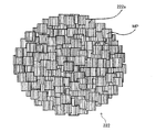
- the positive electrode active material particles 222 are composed of lithium-nickel composite oxide single crystal primary particles 222a having a layered rock salt structure (average particle diameter is 0.01 to 5 ⁇ m). Are secondary particles.
- the single crystal primary particles 222a have the (003) plane indicated by “MP” in the drawing in-plane orientation (that is, the (003) plane is oriented so as to intersect the plate surface of the single crystal primary particles 222a). Is formed. Needless to say, all the (003) planes are parallel to each other in one single crystal primary particle 222a.
- the positive electrode active material particles 222 of the present embodiment have a high uniaxial orientation with a (003) plane. That is, in the positive electrode active material particles 222, a large number of single crystal primary particles 222a constituting the positive electrode active material particles 222 are arranged so that the orientations of the (003) planes are aligned with each other (the (003) planes are as parallel as possible to each other). Is provided). Specifically, the orientation of the (003) plane is such that the orientation ratio of the (003) plane is 50% or more (with respect to the total number of the plurality of single crystal primary particles 222a included in the positive electrode active material particles 222). The positive electrode active material particles 222 are formed so that the ratio of the single crystal primary particles 222a having the same is 50% or more.
- the (003) plane is substantially uniaxially oriented (specifically, the orientation ratio of the (003) plane is 50. %),
- the lithium ion diffusion resistance between the single crystal primary particles 222a is reduced, and the lithium ion conductivity and the electron conductivity are improved.
- the charge / discharge characteristic (especially rate characteristic) of the lithium secondary battery 1 can be remarkably improved.
- microcracks that normally occur between the single crystal primary particles 222a (ie, at grain boundaries) due to volume expansion and contraction due to repeated charge and discharge are parallel to the (003) plane that is the lithium ion diffusion plane and the electron conduction plane ( That is, it becomes easy to enter in a direction that does not affect the diffusion of lithium ions and does not affect the electron conductivity. For this reason, it is possible to suppress deterioration of charge / discharge characteristics (particularly rate characteristics) due to repeated charge / discharge cycles.
- the positive electrode active material particle 222 of the present embodiment which is a secondary particle formed by aggregating a plurality of single crystal primary particles 222a of a lithium-nickel composite oxide having a layered rock salt structure, due to the above-described orientation, Polarization at the end of discharge is greatly improved. Therefore, according to the positive electrode active material particle 222 of the present embodiment, when using a nickel-cobalt-aluminum-based positive electrode active material, higher output (higher capacity at the time of high-rate discharge), and polarization at the end of discharge. Suppression of substantial capacity reduction due to the improvement and good cycle characteristics are realized.
- the orientation ratio of the (003) plane is preferably 70% or more, and particularly preferably 90%.
- the ratio at which the in-plane directions of the (003) plane are parallel to each other in the number of single crystal primary particles 222a included in the positive electrode active material particles 222 as the orientation ratio is higher. Can be said to increase. For this reason, as the orientation ratio is higher, the diffusion distance of lithium ions is shortened and the diffusion resistance of lithium ions is reduced as described above, so that the charge / discharge characteristics of the lithium secondary battery 1 are significantly improved.
- the purpose is to improve durability, increase capacity, and improve safety. As described above, even when the average particle diameter of the positive electrode active material particles 222 is increased, it is possible to maintain high rate characteristics by increasing the orientation ratio.
- the average particle diameter of the single crystal primary particles 222a is 0.01 to 5 ⁇ m, preferably 0.05 to 3 ⁇ m, and more preferably 0.05 to 1.5 ⁇ m.
- the crystallinity of the single crystal primary particles 222a is ensured by setting the average particle diameter of the single crystal primary particles 222a within the above range. If the average particle diameter of the single crystal primary particles 222a is less than 0.1 ⁇ m, the crystallinity of the single crystal primary particles 222a may be reduced, and the output characteristics of the lithium secondary battery 1 may be reduced. However, in the positive electrode active material of the present invention, even if the average particle size of the single crystal primary particles 222a is 0.1 to 0.01 ⁇ m, no significant reduction in output characteristics is observed.
- the positive electrode active material particles 222 as the secondary particles The occurrence of cracks is suppressed as much as possible.
- the average particle diameter of the single crystal primary particles 222a is more than 5 ⁇ m, the positive electrode active material particles as the secondary particles due to the stress generated when the volume of the single crystal primary particles 222a expands or contracts during charging and discharging. 222 may crack.
- the average particle diameter of the positive electrode active material particles 222 as secondary particles is 1 to 100 ⁇ m, preferably 2 to 70 ⁇ m, and more preferably 3 to 50 ⁇ m.
- the average particle diameter of the positive electrode active material particles 222 is 1 to 100 ⁇ m, preferably 2 to 70 ⁇ m, and more preferably 3 to 50 ⁇ m.
- the filling property of the positive electrode active material in the positive electrode active material particles 222 is ensured (the filling rate is improved).
- a flat electrode surface can be formed while maintaining the output characteristics of the lithium secondary battery 1.
- the average particle diameter of the positive electrode active material particles 222 is less than 1 ⁇ m, the filling rate of the positive electrode active material may be reduced.
- the average particle diameter of the positive electrode active material particles 222 exceeds 100 ⁇ m, the output characteristics of the lithium secondary battery 1 may be degraded, and the flatness of the electrode surface may be degraded.
- the distribution of the average particle diameter of the positive electrode active material particles 222 may be sharp, broad, or have a plurality of peaks. For example, when the average particle size distribution of the positive electrode active material particles 222 is not sharp, the packing density of the positive electrode active material in the positive electrode active material layer 22 is increased, or the adhesion between the positive electrode active material layer 22 and the positive electrode current collector 21 is increased. Can be increased. Thereby, rate characteristics and cycle characteristics can be further improved.
- the aspect ratio of the positive electrode active material particles 222 is 1.0 or more and less than 2.0, and preferably 1.1 to 1.5. Even if the packing density of the positive electrode active material in the positive electrode active material layer 22 is increased by setting the aspect ratio of the positive electrode active material particles 222 within this range, the electrolysis impregnated in the positive electrode active material layer 22 is achieved. It is possible to form an appropriate gap between the positive electrode active material particles 222 so as to ensure a path through which lithium ions in the liquid 5 diffuse in the thickness direction of the positive electrode active material layer 22. Thereby, the output characteristics of the lithium secondary battery 1 can be further improved.
- the positive electrode active material particles 222 are arranged in the plate surface direction of the positive electrode current collector 21 and the major axis direction of the particles when the positive electrode active material layer 22 is formed. It becomes easy to fill in a state in which and are arranged in parallel. Then, the diffusion path of the lithium ions in the electrolyte solution 5 impregnated in the positive electrode active material layer 22 in the thickness direction of the positive electrode active material layer 22 becomes long. For this reason, the output characteristics of the lithium secondary battery 1 may deteriorate.
- the aspect ratio of the single crystal primary particles 222a is preferably 1.0 or more and 2.0 or less, and more preferably 1.1 or more and 1.5 or less. The reason for this is as follows.
- the single crystal primary particles of the positive electrode active material are likely to grow in an orientation parallel to the (003) plane, which is a conductive surface for lithium ions and electrons. For this reason, generally, in such single crystal primary particles, the aspect ratio tends to be large (the particles have a flat shape). At the same time, many (003) planes, which are crystal planes from which lithium ions and electrons hardly enter and exit, are exposed on the surface.
- the aspect ratio of the single crystal primary particles 222a to 2.0 or less, a surface where lithium ions and electrons easily enter and exit at the contact portion between the adjacent single crystal primary particles 222a ( That is, the contact between the surfaces other than the (003) surface can be sufficiently ensured, and therefore, the lithium ion conductivity and the electron conductivity in the positive electrode active material particles 222 as the secondary particles are favorably ensured. In particular, this effect is remarkable when the crystal plane orientation of the positive electrode active material particles 222 is high.
- the positive electrode active material particles 222 are densely formed (that is, in a state where a large number of single crystal primary particles 222a are densely packed without gaps), the positive electrode active material layers 22 in the positive electrode active material layer 22 are formed.
- the packing density of the substance can be increased, which is advantageous for increasing the capacity.
- the electrolyte solution and the conductive material can be contained in the gap 222b.
- rate characteristics can be improved while maintaining a high capacity.
- the stress at the time of charging / discharging can also be relieved and the capacity deterioration (cycle characteristic) by repetition of charging / discharging can also be improved.
- the degree of introduction of the void 222b can be defined by “void ratio”, “average pore diameter”, and “open pore ratio”.
- FIG. 6 is a schematic view showing a part of the positive electrode active material particles 222 shown in FIG. 5 in an enlarged manner.
- (Ii) in FIG. 6 is a schematic diagram showing an enlarged part of a conventional positive electrode active material particle 222 ′ as a comparative example.
- the (003) plane (see “MP” in the drawing) of the single crystal primary particles 222a constituting the positive electrode active material particles 222 including the voids 222b is in a specific direction.
- the resistance (grain boundary resistance) at the grain boundary GB is reduced.
- the reduction of the grain boundary resistance and the void 222b containing the electrolytic solution and the conductive material maximize the lithium ion conductivity and the electron conductivity in the positive electrode active material particle 222 including the void 222b.
- voids 222b are included in conventional positive electrode active material particles 222 ′ in which the (003) plane of the single crystal primary particles 222a is not oriented in a specific direction.
- the electrolyte solution and the conductive material penetrate into the gap 222b, the lithium ion conductivity and the electron conductivity are reduced because the conduction path of lithium ions and electrons becomes narrow.
- the narrowest part (neck part) of the conduction path is often the grain boundary GB, and when the grain boundary resistance is high, the decrease in conductivity becomes significant (note that the grain boundary resistance is actually Although not observed, an image showing the level of the grain boundary resistance is shown at the grain boundary GB in the figure.
- “Voidage” is the volume ratio of voids 222 b (pores: including open pores and closed pores) in the positive electrode active material particles 222.
- “Porosity” is sometimes referred to as “porosity”. This “porosity” can be calculated from, for example, the bulk density and the true density. Specifically, the relative density is obtained by dividing the bulk density obtained by the Archimedes method by the true density obtained using a pycnometer. Subsequently, the porosity is calculated
- the porosity is preferably 60% or less, more preferably 50% or less, and even more preferably 40% or less.
- Average pore diameter is the average value of the diameters of the pores in the positive electrode active material particles 222.
- the “diameter” is typically a diameter of the sphere when the pore is assumed to be a sphere having the same volume or the same cross-sectional area.
- the “average value” is suitably calculated based on the number.
- the average pore diameter can be determined by a known method such as image processing of a cross-sectional SEM photograph or mercury intrusion method. More specifically, the average pore diameter can be measured by a mercury intrusion method using a mercury intrusion pore distribution measuring device (manufactured by Shimadzu Corporation, device name “Autopore IV9510”).
- the average pore diameter is preferably 0.01 to 5 ⁇ m, more preferably 0.05 to 4.5 ⁇ m, and still more preferably 0.1 to 4.0 ⁇ m.
- the average pore diameter is more than 5 ⁇ m, relatively large pores are generated. When such large pores exist, the amount per volume of the positive electrode active material that contributes to charge / discharge decreases. In addition, stress concentration is likely to occur locally in such large pores, and it is difficult to obtain the effect of releasing stress uniformly inside.
- the average pore diameter is less than 0.01 ⁇ m, it is difficult to contain the conductive material and the electrolyte, and the stress releasing effect by the pores is insufficient. For this reason, the effect of improving rate characteristics and cycle characteristics while maintaining a high capacity may not be expected.
- the “open pore ratio” is a volume ratio of open pores to the whole voids (pores) included in the positive electrode active material particles 222.
- Open pores refer to pores 222 b (pores) included in the positive electrode active material particles 222 that communicate with the outside of the positive electrode active material particles 222.
- This “open pore ratio” can be calculated from, for example, the sum of the open pores and closed pores obtained from the bulk density and the closed pores obtained from the apparent density.
- the parameters used for calculating the “open pore ratio” can be measured using Archimedes method or the like.
- the inner wall surface (surface) of the positive electrode active material particles 222 constituting the open pores functions well as a surface through which lithium ions enter and exit. Therefore, it is preferable to set the open pore ratio to 50% or more from the viewpoint of improving rate characteristics as compared with a case where the ratio of closed pores existing as simple pores (portions that do not contribute to charge / discharge) is large.
- the open pore ratio for example, 70% or more
- the rate characteristics are further improved while maintaining a high capacity, and further the cycle Properties are also improved.
- a particulate or fibrous substance that is decomposed (evaporated or carbonized) in the pre-baking step can be suitably used.
- particulate or fibrous materials of organic synthetic resins such as theobromine, nylon, graphite, phenol resin, polymethyl methacrylate, polyethylene, polyethylene terephthalate, and foamable resin can be suitably used.
- Other compounds may be present in the gap 222b.
- an electrolyte, a conductive material, other lithium ion positive electrode active materials having excellent rate characteristics, positive electrode active materials having different particle diameters, and the like are present in the gap 222b, the rate characteristics and cycle characteristics are further improved.
- a method for causing the other compound to exist in the void 222b a method of applying the compound to the surface of the void forming material in advance and adjusting the firing conditions, or forming the positive electrode active material particles 222 is possible. There is a method of mixing a compound with raw material particles.
- the surface of the single crystal primary particles 222a or the positive electrode active material particles 222 may be coated with another material.
- the thermal stability and chemical stability of the material are improved, and the rate characteristics are improved.
- the coating material for example, the following materials can be used: chemically stable alumina, zirconia, fluorinated alumina, etc .; materials such as lithium cobaltate having excellent lithium diffusibility; Excellent carbon.
- the positive electrode active material particles 222 of this embodiment can be manufactured, for example, by a manufacturing method as described below.
- FIG. 7 is a diagram schematically showing an example of such a manufacturing method.
- raw material particles particles obtained by appropriately mixing particles of compounds such as Li, Co, Ni, Mn, and Al so that the composition of the positive electrode active material is LiMO 2 can be used. Specifically, for example, mixed particles ((Co, Ni, Mn) O x , (Co, Ni, Al) O x , (Co , Ni, Mn) OH x , (Co, Ni, Al) OH x , etc.). By molding these mixed particles and further reacting the obtained compact with the lithium compound, positive electrode active material particles having a predetermined composition can be obtained.
- a hydroxide having a composition such as (Co, Ni, Mn) OH x , (Co, Ni, Al) OH x , or the like as the raw material particles.
- a hydroxide has a shape of flat primary particles having a (001) plane on a flat surface, and the primary particles are easily oriented by a molding process described later.
- the (001) plane is a plane whose orientation is inherited as the (003) plane in the positive electrode active material having a predetermined composition by reacting with the lithium compound. For this reason, by using such plate-like raw material particles, the (003) plane in the positive electrode active material particles 222 can be easily oriented.
- a large amount of lithium compound may be introduced into the raw material particles so that the lithium is in an excess of 0.5 to 40 mol%. .
- 0.001 to 30% by mass of low melting point oxide (such as bismuth oxide), low melting point glass (such as borosilicate glass), lithium fluoride, or lithium chloride is added to the raw material particles. May be.
- a void forming material for forming voids having desired “porosity”, “average pore diameter”, and “open pore ratio” may be added.
- the prepared raw material particles are molded into a sheet-like self-supporting molded body having a thickness of 100 ⁇ m or less.
- self-supporting in the “self-supporting molded body” is synonymous with “independent” in the “independent sheet” described later. That is, the “self-supporting molded body” is, as a rule, capable of maintaining the shape of a sheet-shaped molded body by itself. However, even if it cannot maintain the shape of a sheet-like molded body by itself at a certain time, it is once formed into a sheet by pasting or forming a film on some substrate. What has been peeled off from the substrate before or after firing is also included in the “self-supporting molded body”.
- the extruded sheet is a “self-supported molded body” immediately after molding.
- the slurry coating film cannot be handled alone before drying, but becomes a “self-supporting molded body” after drying and peeling from the substrate.
- sheet shape includes plate shape, flake shape, scale shape, and the like.
- the molding method is not particularly limited as long as the raw material particles are filled in the molded body with the same crystal orientation.
- a slurry containing raw material particles by using a doctor blade method, it is possible to obtain a (self-supporting sheet-like) molded body in which the raw material particles are filled in the same crystal orientation.
- a doctor blade method when using the doctor blade method, first, a slurry S (see (i) in FIG. 7) containing raw material particles 701 on a flexible substrate (for example, an organic polymer plate such as a PET film) is used.
- the applied slurry S is dried and solidified to form a dry film.
- the dry film is peeled from the above-described substrate to obtain a shaped body 702 in which the raw material particles 701 are oriented (filled with the same crystal orientation) (see (ii) in FIG. 7).
- the above-described molded body 702 can be obtained by scraping off a slurry obtained by applying a slurry containing raw material particles on a heated drum using a drum dryer and drying the slurry. Furthermore, the above-mentioned molded object 702 can be obtained by scraping with a scraper what applied and dried the slurry containing raw material particles on the heated disk surface using a disk dryer. Moreover, the above-mentioned molded object 702 can be obtained by extrusion molding using clay containing raw material particles.
- a binder, a plasticizer, or the like may be appropriately added to the raw material particles dispersed in an appropriate dispersion medium.
- the kind and amount of the additive such as a binder are appropriately adjusted so that the packing density and orientation degree of the raw material particles at the time of molding or the shape of the pulverized product in the pulverization step described later can be controlled to a desired state.
- the kind and addition amount of a binder, a plasticizer, etc. can be adjusted suitably so that the softness
- the viscosity When using a slurry containing raw material particles, it is preferable to adjust the viscosity to be 0.5 to 5 Pa ⁇ s or to defoam under reduced pressure. Furthermore, when another compound is present in the voids, it is preferable to prepare a slurry containing this compound and raw material particles.
- the thickness of the molded body 702 is preferably 120 ⁇ m or less, and more preferably 100 ⁇ m or less. Moreover, it is preferable that the thickness of the molded object 702 is 1 micrometer or more. If the thickness of the molded body 702 is 1 ⁇ m or more, it becomes easy to produce a self-supporting sheet-shaped molded body. Note that the thickness of the formed body 702 is a direct factor that determines the average particle diameter of the positive electrode active material particles 222, and thus is appropriately set according to the use of the particles.
- the obtained formed body 702 is crushed so that the positive electrode active material particles 222 have a desired aspect ratio.
- the following can be used: a method of pressing the mesh with a spatula or the like; a method of crushing with a crusher having a weak crushing force such as a pin mill; Specifically, a method of feeding into an air classifier); swirling jet mill; pot crushing; barrel polishing;
- the process for spheroidizing the crushed material may be performed.
- the positive electrode active material particles 222 finally obtained have a substantially spherical shape or a substantially spheroid shape. Since the positive electrode active material particles 222 are substantially spherical or spheroid, the exposure of the lithium ion entrance / exit surface on the outer surface of the particles is increased, and the positive electrode active material filling rate in the positive electrode active material layer 22 is increased. As a result, the battery characteristics are improved.
- the following method can be used: a method of taking “corners” of the crushed particles by colliding the crushed particles with each other in an air stream (airflow classification, hybridization, etc.); Method of removing “corner” of crushed particles by colliding crushed particles with each other (method using hybrid mixer or high speed stirrer / mixer, barrel polishing, etc.); mechanochemical method; crushed particles by hot air Method of melting the surface of the.
- the spheronization treatment and crushing may be performed separately, but may be performed simultaneously. That is, for example, by using an airflow classifier, crushing and spheronization can be performed simultaneously.
- the molded body may be degreased or heat-treated (fired or temporarily fired) in advance.
- the molded body may be dried at a relatively high temperature at which the binder is denatured or decomposed.
- the raw material particles are plate-shaped (for example, when the raw material particles are hydroxide)
- the molded body before pulverization has many plate-shaped raw material particles arranged in parallel with the plate surface of the molded body. The internal structure looks like an agglomeration.
- the internal structure of the molded body before crushing and before firing (before lithium introduction) can be brought into a state in which an oxide having an isotropic shape is necked. It becomes easy to set the aspect ratio of the crushed material to 2 or less.
- the calcination temperature is preferably in the range of 600 to 1100 ° C. When the calcination temperature is less than 600 ° C., the above-described progress of necking becomes insufficient, and the molded body after the calcination becomes brittle, so that the particle size of the crushed material becomes too fine due to crushing.
- Such preliminary firing before crushing is a composition in which adverse effects such as phase separation are not easily caused by temporary firing (for example, nickel-cobalt-based, nickel-cobalt-aluminum-based, nickel-aluminum-based, etc.) containing nickel while containing manganese. It is particularly preferred to be carried out in a system that does not contain.
- the state in which the raw material particles (plate-shaped raw material particles) 701 are well oriented remains in the positive electrode active material precursor particles 703 that are the pulverized product obtained. (See (iii) in FIG. 7). That is, the positive electrode active material precursor particles 703 are raw material particle aggregates containing a large number of plate-like raw material particles 701, and these raw material particles 701 are formed so as to be substantially uniformly oriented.
- the positive active material precursor particles 704 that are the obtained crushed material have raw material particles ( The state in which the (plate-like raw material particles) 701 are oriented does not remain (see (iv) in FIG. 7). That is, the positive electrode active material precursor particles 704 have an internal structure corresponding to the heat-treated positive electrode active material precursor particles 703. Therefore, after positive electrode active material precursor particles 703 are obtained by pulverization without performing temporary firing, the positive electrode active material precursor particles 704 can be formed by temporary firing.
- those other than the desired aspect ratio (such as those that are not sufficiently crushed and remain in a large aspect ratio) and fine powder can be reused as raw materials.
- the aspect ratio is 1.0 or more and less than 2.0 (preferably 1.1 to 1) so that the positive electrode active material particles 222 have a desired aspect ratio and a desired (003) plane orientation state. 5), positive electrode active material precursor particles 703 or 704 having a predetermined internal structure are formed.
- the positive electrode active material precursor particles 703 or 704 those produced by a production method other than the above (1) to (3) can be used.
- a hydroxide having a composition such as (Co, Ni, Mn) OH x or (Co, Ni, Al) OH x obtained as follows, having an aspect ratio of 1.0 or more and 2
- particles having a substantially spherical shape and a desired (001) plane orientation state of less than 0.0 are also possible to use.
- Co, Ni, Mn, or Co is added to a reaction vessel in which hydroxide seed crystal particles having a composition such as (Co, Ni, Mn) OH x or (Co, Ni, Al) OH x are added in advance.
- An aqueous solution containing Ni, Al, a complexing agent, and an alkali metal hydroxide are supplied with continuous stirring, thereby producing Co, Ni, Mn, or a complex salt of Co, Ni, Al. .
- this complex salt by decomposing this complex salt with an alkali metal hydroxide, the crystal orientation ((Co, Ni, Mn) OH x or (Co, Ni, Al) OH x (001) is introduced around the seed crystal.
- Co, Ni, Mn, or Co, Ni, Al hydroxide is deposited so that the surface is aligned.
- a mixture before firing is obtained.
- a lithium compound lithium hydroxide, lithium carbonate, etc.
- the average particle size of the lithium compound is preferably 0.1 to 5 ⁇ m.
- the lithium compound can be easily handled from the viewpoint of hygroscopicity.
- the reactivity with a crushed material increases that the average particle diameter of a lithium compound is 5 micrometers or less. In order to increase the reactivity, it is possible to keep the amount of lithium excessive by 0.5 to 40 mol%.
- Firing main firing: introduction of lithium
- the positive electrode active material precursor particles 703 or 704 By firing the above-mentioned mixture before firing by an appropriate method, lithium is introduced into the positive electrode active material precursor particles 703 or 704, whereby the positive electrode active material particles 222 are obtained.
- firing can be performed by putting a sheath containing the mixture before firing in a furnace.
- synthesis of the positive electrode active material, and further, particle sintering and particle growth are performed.
- the (001) plane of the raw material particles is oriented in the compact (positive electrode active material precursor particles 703 or 704), the crystal orientation is inherited, so that a predetermined composition is obtained.
- the (003) plane can be favorably uniaxially oriented.
- the firing temperature is preferably 600 ° C to 1100 ° C. When the firing temperature is lower than 600 ° C., grain growth is insufficient and the orientation rate may be lowered. On the other hand, when the firing temperature is higher than 1100 ° C., the decomposition of the positive electrode active material and the volatilization of lithium progress, and the predetermined composition may not be realized.
- the firing time is preferably 1 to 50 hours. If the firing time is shorter than 1 hour, the orientation ratio may be lowered. On the other hand, if the firing time is longer than 50 hours, the energy consumed for firing may be too large.
- the firing atmosphere must be set appropriately so that decomposition does not proceed during firing.
- firing is preferably performed in an atmosphere having a high oxygen partial pressure.
- pulverization and classification (the above-mentioned pre-fired solution is appropriately performed). Since it is performed after crushing and classification, it may be referred to as “secondary crushing” or “secondary classification”). Or the above-mentioned crushing process may be performed after baking. That is, the crushing step (and classification step) may be performed only after firing.
- Orientation rate (%) Secondary particle powder was arranged on a glass substrate so that secondary particles might not overlap as much as possible.
- a sample for observation was prepared by polishing a powder obtained by copying this powder onto an adhesive tape and embedding it in a synthetic resin so that the plate surface or cross-section polished surface of the secondary particles can be observed.
- polishing was performed with a vibration type rotary polishing machine using colloidal silica (0.05 ⁇ m) as an abrasive.
- polishing was performed with a cross section polisher (CP).
- a histogram (angle distribution) of the number of particles with respect to the angle is output, and the angle at which the number of primary particles is maximum (peak value) is defined as the (003) plane inclination angle ⁇ with respect to the measurement surface of the secondary particles.
- the number of primary particles having a (003) plane within ⁇ ⁇ 10 degrees was calculated for the measured secondary particles.
- the orientation ratio of the (003) plane in the measured secondary particles was calculated. This was performed for 10 different secondary particles, and the average value was defined as the orientation ratio of the (003) plane.
- discharge capacity at 2C rate The measured value of the discharge capacity at the second cycle was defined as “discharge capacity at 2C rate”.
- the value obtained by dividing the “discharge capacity at the 2C rate” by the “discharge capacity at the 0.1C rate” was defined as the rate capacity maintenance rate.
- Nickel-cobalt-aluminum composition (Example 1) (1) Preparation of raw material particles and slurry Ni (OH) 2 powder (manufactured by Kojundo Chemical Laboratory Co., Ltd.), Co (so that the molar ratio of Ni, Co, Al in the mixture is 75: 20: 5 OH) 2 powder (manufactured by High-Purity Chemical Laboratory Co., Ltd.) and Al 2 O 3 .H 2 O (manufactured by SASOL) are weighed, and the weighed material is pulverized and mixed for 16 hours with a ball mill, whereby raw material particles A powder was prepared.
- a binder polyvinyl butyral: product number BM-2, manufactured by Sekisui Chemical Co., Ltd.
- a plasticizer DOP: Di (2-ethylhexyl) phthalate, manufactured by Kurokin Kasei Co., Ltd.
- a dispersant product name “Leodol SP-O30”, manufactured by Kao Corporation
- the mixture was defoamed by stirring under reduced pressure, and a slurry was prepared by adjusting the viscosity to 3 to 4 Pa ⁇ s (viscosity was measured using a Brookfield LVT viscometer). It was measured.).
- Firing step (lithium introduction step)
- the mixed powder described above is put into a crucible made of high-purity alumina and heat-treated at 750 ° C. for 12 hours in an oxygen atmosphere (0.1 MPa), so that Li (Ni 0.75 Co 0.2 Al 0 .05 ) O 2 powder was obtained.
- coin cell batteries were prepared as follows. By mixing the obtained Li (Ni 0.75 Co 0.2 Al 0.05 ) O 2 powder, acetylene black, and polyvinylidene fluoride (PVDF) so as to have a mass ratio of 75: 20: 5.
- a positive electrode material was prepared.
- a positive electrode active material layer was produced by press-molding 0.02 g of the prepared positive electrode material into a disk shape having a diameter of 20 mm at a pressure of 300 kg / cm 2 .
- a coin cell as shown in FIG. 1 was produced using the produced positive electrode active material layer.
- the electrolytic solution was prepared by dissolving LiPF 6 in an organic solvent in which ethylene carbonate (EC) and diethyl carbonate (DEC) were mixed at an equal volume ratio to a concentration of 1 mol / L.
- EC ethylene carbonate
- DEC diethyl carbonate
- Li (Ni) was prepared in the same manner as in Example 1, except that the opening diameter of the sieve (mesh) was 20 ⁇ m (Example 2) and 25 ⁇ m (Example 3).
- a 0.75 Co 0.2 Al 0.05 ) O 2 powder was prepared.
- Example 4 In “(2) Forming raw material particles”, the same method as in Example 1 except that the feed rate in the doctor blade method was set to 0.5 m / s (Example 4) and 5 m / s (Example 5). , Li (Ni 0.75 Co 0.2 Al 0.05 ) O 2 powder was prepared.
- NiO powder manufactured by Shodo Chemical Industry Co., Ltd.
- Co 3 O 4 powder manufactured by Shodo Chemical Industry Co., Ltd.
- Al 2 O 3 powder manufactured by Showa Denko KK
- Li (Ni 0.75 Co 0.2 Al 0.05 ) O 2 powder was prepared in the same manner as in Example 1 except that a sieve (mesh) having an opening diameter of 25 ⁇ m was used in “Crushing the body”. did.
- Example 13 With respect to the manufacturing method of Example 13 described above, the feeding speed at the time of tape molding, presence / absence of temporary firing, mesh opening diameter, presence / absence of spheronization treatment (when spheroidization treatment is not performed, the same as Example 1 described above)
- the powders of Examples 6 to 12, Example 14 and Comparative Example 4 were obtained (see Table 2).
- powders of Comparative Examples 2 and 3 were obtained by using spray drying instead of tape molding (see Table 2).
- Powder molding by spray drying was performed as follows: using a spray dryer (manufactured by Sakamoto Giken Co., Ltd .: turning type TSR-3W), liquid amount 40 g / min, inlet temperature 200 ° C., atomizer rotation speed 13000 rpm. Under conditions, spherical granules were obtained.
- Example 6 to 14 and Comparative Examples 2 to 4 Evaluation was performed in the same manner as in Example 1 and the like.
- the aspect ratios of the particles before firing (precursor particles) in Examples 6 to 14 and Comparative Examples 2 to 4 were determined by the method described above.
- the evaluation batteries used for the battery characteristics evaluation were prepared in the same manner as in Example 1 except for the following.
- Li (Ni 0.8 Co 0.15 Al 0.05 ) O 2 powder, acetylene black, and polyvinylidene fluoride (PVDF) were mixed at a mass ratio of 90: 5: 5, and N
- a positive electrode active material paste was prepared by dispersing in -methyl-2-pyrrolidone. This paste was applied on an aluminum foil having a thickness of 20 ⁇ m as a positive electrode current collector so as to have a uniform thickness (thickness after drying: 50 ⁇ m), and punched out into a disk shape having a diameter of 14 mm from the dried sheet.
- a positive electrode plate was produced by pressing the product at a pressure of 2000 kg / cm 2 .
- a coin cell as shown in FIG. 1 was produced using the produced positive electrode plate.
- Example 7 when comparing Examples 6 to 14, the rate characteristic of Example 7 that performed the spheroidizing process was higher than that of Example 6 that did not perform the spheronizing process. Similarly, higher rate characteristics were obtained in Example 9 in which the spheronization process was performed than in Example 8 in which the spheronization process was not performed.
- the relationship between Examples 10 and 11 and Examples 12 and 13 was the same. Further, when Examples 7, 8, 11 and 12 using the same mesh were examined, the aspect ratio of the particles was closer to 1 and the rate characteristics were better when pre-baked (Examples 12 and 13). It became good.
- FIG. 8 the SEM photograph of the positive electrode active material particle of Example 13 is shown.
- FIG. 9 shows a higher magnification SEM photograph of the particles of the example (specifically, example 13).
- FIG. 10 shows a graph of discharge characteristics when the positive electrode active material particles of the examples and comparative examples are used.
- the solid line indicates the case where the particles of Example 13 are used
- the alternate long and short dash line indicates the case where the particles of Comparative Example 2 are used.
- a high voltage is satisfactorily maintained even immediately before the end of discharge. This is considered to be because the internal resistance in the positive electrode is reduced when the particles of the example are used.
- the ratio P of the discharge capacity when the discharge voltage is 3.5 V to the discharge capacity when the discharge voltage reaches 3 V is used as an index to determine the degree of polarization. evaluated. The closer this ratio is to 1, the smaller the polarization.
- Example 13 orientation
- Comparative Example 2 non-orientation
- the particle size and particle shape were almost the same and only the orientation state was different.
- the test temperature was set to 25 ° C.
- Cycle charge / discharge was performed.
- As an index of cycle characteristics a change in the rate capacity retention rate (same as in Example 1, 2C / 0.1C) in the battery before and after 50 cycles of charge / discharge was measured.
- Comparative Example 2 85% decreased to 74% before and after cycle charge / discharge, whereas in Example 13, the decrease was only from 95% to 90%.
- the configuration of the lithium secondary battery 1 to which the present invention is applied is not limited to the configuration described above.
- the present invention is not limited to the specific battery configuration as described above. That is, for example, as shown in FIG. 11, the present invention can also be suitably applied to a cylindrical lithium secondary battery 1 wound around a winding core 7.
- the present invention is not limited to a so-called liquid battery configuration. That is, for example, a gel polymer electrolyte or a polymer electrolyte can be used as the electrolyte.
- the orientation of the surface layer portion of the positive electrode active material particles 222 may be lower than the inside.
- the single crystal primary particles 222a are also formed in a region having a (003) plane that is difficult for lithium ions and electrons to enter and exit and having a widely exposed surface (see a region surrounded by an ellipse in a broken line in the figure). Lithium ions easily enter and exit from the outer electrolyte, thereby improving rate characteristics.
- Such a surface layer can be formed, for example, by reattaching the fine powder generated during the crushing or spheronizing treatment to the particles (this can be achieved by appropriately adjusting the conditions of the crushing or spheroidizing treatment). Becomes).
- Such an intragranular microstructure is, for example, an EBSD (electron backscattering diffraction image) in SEM observation of a cross section of a secondary particle (processed by a cross section polisher (CP), a focused ion beam (FIB), or the like). Method) and crystal orientation analysis in TEM observation.
- EBSD electron backscattering diffraction image
- CP cross section polisher
- FIB focused ion beam
- the present invention is not limited to the specific manufacturing method described above. That is, for example, the molding method is not limited to the above-described method. Moreover, the above-mentioned baking (lithium introduction) process can be skipped by selecting the raw material before shaping
- the positive electrode in which the raw material particles 701 are oriented (filled with the same crystal orientation) by applying a magnetic field during molding, etc.
- active material precursor particles 703 or positive electrode active material precursor particles 704 may be obtained. Therefore, the present invention is not limited to the case where hydroxide is used as the raw material particles.
- the positive electrode active material precursor particles of the present invention are provided to the market in a state containing a lithium compound (including internal addition and / or external addition of the lithium compound to the particle) and in a state mixed with the lithium compound. Can be done.
- the particles containing the lithium compound and the particles mixed with the lithium compound may be referred to as “positive electrode active material precursor particles that become the positive electrode active material particles of the lithium secondary battery by heat treatment”. It goes without saying that these can also be the subject of the present invention.
Landscapes
- Chemical & Material Sciences (AREA)
- Organic Chemistry (AREA)
- Inorganic Chemistry (AREA)
- Chemical Kinetics & Catalysis (AREA)
- Electrochemistry (AREA)
- General Chemical & Material Sciences (AREA)
- Battery Electrode And Active Subsutance (AREA)
- Inorganic Compounds Of Heavy Metals (AREA)
Abstract
L'invention concerne des particules de matériau actif de cathode pour une batterie secondaire au lithium, se présentant sous la forme de particules secondaires résultant de l'agrégation d'une pluralité de particules primaires monocristallines d'un oxyde composite lithium-nickel possédant une structure halite stratifiée. Les particules primaires possèdent une taille de particule moyenne de 0.01-5 μm, et les particules secondaires possèdent un rapport de forme, qui correspond à la valeur de division du diamètre de l'axe majeur par le diamètre de l'axe mineur, d'au moins 1,0 et de moins de 2, une taille de particule moyenne de 1-100 μm et un plan (003) à orientation sensiblement monoaxiale. Cette configuration permet d'améliorer encore les caractéristiques de batteries au lithium, notamment les caractéristiques de cycle et de charge/décharge grande vitesse.
Priority Applications (1)
| Application Number | Priority Date | Filing Date | Title |
|---|---|---|---|
| JP2013508781A JPWO2012137535A1 (ja) | 2011-04-07 | 2012-02-07 | 正極活物質前駆体粒子、リチウム二次電池の正極活物質粒子、及びリチウム二次電池 |
Applications Claiming Priority (6)
| Application Number | Priority Date | Filing Date | Title |
|---|---|---|---|
| US201161472805P | 2011-04-07 | 2011-04-07 | |
| US61/472,805 | 2011-04-07 | ||
| US201161496721P | 2011-06-14 | 2011-06-14 | |
| US61/496,721 | 2011-06-14 | ||
| US201161527306P | 2011-08-25 | 2011-08-25 | |
| US61/527,306 | 2011-08-25 |
Publications (1)
| Publication Number | Publication Date |
|---|---|
| WO2012137535A1 true WO2012137535A1 (fr) | 2012-10-11 |
Family
ID=46966358
Family Applications (1)
| Application Number | Title | Priority Date | Filing Date |
|---|---|---|---|
| PCT/JP2012/052719 WO2012137535A1 (fr) | 2011-04-07 | 2012-02-07 | Particules précurseurs de matériau actif de cathode, particules précurseurs de matériau actif de cathode pour batterie secondaire au lithium et batterie secondaire au lithium |
Country Status (3)
| Country | Link |
|---|---|
| US (1) | US20120258365A1 (fr) |
| JP (1) | JPWO2012137535A1 (fr) |
| WO (1) | WO2012137535A1 (fr) |
Cited By (7)
| Publication number | Priority date | Publication date | Assignee | Title |
|---|---|---|---|---|
| WO2014061399A1 (fr) * | 2012-10-15 | 2014-04-24 | 日本碍子株式会社 | Matériau actif positif pour batterie secondaire au lithium, et électrode positive obtenue à l'aide de celui-ci |
| WO2014061580A1 (fr) * | 2012-10-15 | 2014-04-24 | 日本碍子株式会社 | Processus de fabrication d'une matière active d'électrode positive pour une batterie rechargeable au lithium, et poudre de précurseur de matière active devant être utilisée dans ledit processus |
| JP2019133937A (ja) * | 2018-01-31 | 2019-08-08 | 住友金属鉱山株式会社 | 非水系電解質二次電池用正極活物質 |
| WO2020055210A1 (fr) | 2018-09-12 | 2020-03-19 | 주식회사 포스코 | Matériau actif de cathode, son procédé de préparation et batterie rechargeable au lithium le comprenant |
| JP2020109771A (ja) * | 2014-09-11 | 2020-07-16 | エコプロ ビーエム カンパニー リミテッドEcopro Bm Co., Ltd. | リチウム二次電池用正極活物質及びこれを含むリチウム二次電池 |
| WO2021040031A1 (fr) * | 2019-08-30 | 2021-03-04 | 住友金属鉱山株式会社 | Matériau actif d'électrode positive pour batteries secondaires au lithium-ion et batterie secondaire au lithium-ion |
| KR20220036961A (ko) * | 2019-09-26 | 2022-03-23 | 컨템포러리 엠퍼렉스 테크놀로지 씨오., 리미티드 | 이차 전지, 이차 전지를 포함하는 전지 모듈, 전지 팩 및 장치 |
Families Citing this family (11)
| Publication number | Priority date | Publication date | Assignee | Title |
|---|---|---|---|---|
| KR20130138073A (ko) * | 2012-06-08 | 2013-12-18 | 한양대학교 산학협력단 | 리튬 이차 전지용 양극활물질 전구체, 이를 이용하여 제조된 양극활물질 및 이를 포함하는 리튬 이차 전지 |
| KR20230077753A (ko) | 2014-10-27 | 2023-06-01 | 가부시키가이샤 한도오따이 에네루기 켄큐쇼 | 입자, 전극, 전력 저장 장치, 전자 장치, 및 전극의 제작 방법 |
| CN116053451A (zh) | 2016-07-05 | 2023-05-02 | 株式会社半导体能源研究所 | 锂离子二次电池 |
| US11239458B2 (en) * | 2016-09-07 | 2022-02-01 | Gs Yuasa International Ltd. | Energy storage device and method for manufacturing energy storage device |
| DE202017007622U1 (de) | 2016-10-12 | 2023-09-13 | Semiconductor Energy Laboratory Co., Ltd. | Positivelektrodenaktivmaterialteilchen |
| WO2018087966A1 (fr) * | 2016-11-11 | 2018-05-17 | 日本碍子株式会社 | Source d'énergie de ci, divers produits à ci la comportant, procédé de distribution de puissance à un ci, et procédé d'excitation de ci |
| CN111682188A (zh) | 2017-05-12 | 2020-09-18 | 株式会社半导体能源研究所 | 正极活性物质粒子 |
| CN111900358A (zh) | 2017-05-19 | 2020-11-06 | 株式会社半导体能源研究所 | 正极活性物质以及二次电池 |
| CN110337744A (zh) | 2017-06-26 | 2019-10-15 | 株式会社半导体能源研究所 | 正极活性物质的制造方法及二次电池 |
| CN114068912B (zh) * | 2020-08-10 | 2023-09-05 | 巴斯夫杉杉电池材料有限公司 | 一种二元高镍单晶正极材料及其制备方法 |
| KR20230161158A (ko) * | 2022-05-18 | 2023-11-27 | 에스케이온 주식회사 | 리튬 이차 전지용 양극 활물질의 제조 방법, 리튬 이차 전지용 양극 및 리튬 이차 전지 |
Citations (3)
| Publication number | Priority date | Publication date | Assignee | Title |
|---|---|---|---|---|
| JP2008258160A (ja) * | 2007-03-30 | 2008-10-23 | Matsushita Electric Ind Co Ltd | 非水電解質二次電池用活物質およびその製造法 |
| WO2010074302A1 (fr) * | 2008-12-24 | 2010-07-01 | 日本碍子株式会社 | Particules en forme de plaque pour matériau actif d'électrode positive de batteries secondaires au lithium, films de ce matériau, et batteries secondaires au lithium |
| JP2012084502A (ja) * | 2010-10-08 | 2012-04-26 | Ngk Insulators Ltd | リチウム二次電池の正極活物質用の板状粒子 |
Family Cites Families (1)
| Publication number | Priority date | Publication date | Assignee | Title |
|---|---|---|---|---|
| US20040191161A1 (en) * | 2002-11-19 | 2004-09-30 | Chuanfu Wang | Compounds of lithium nickel cobalt metal oxide and the methods of their fabrication |
-
2012
- 2012-02-07 WO PCT/JP2012/052719 patent/WO2012137535A1/fr active Application Filing
- 2012-02-07 US US13/367,827 patent/US20120258365A1/en not_active Abandoned
- 2012-02-07 JP JP2013508781A patent/JPWO2012137535A1/ja active Pending
Patent Citations (3)
| Publication number | Priority date | Publication date | Assignee | Title |
|---|---|---|---|---|
| JP2008258160A (ja) * | 2007-03-30 | 2008-10-23 | Matsushita Electric Ind Co Ltd | 非水電解質二次電池用活物質およびその製造法 |
| WO2010074302A1 (fr) * | 2008-12-24 | 2010-07-01 | 日本碍子株式会社 | Particules en forme de plaque pour matériau actif d'électrode positive de batteries secondaires au lithium, films de ce matériau, et batteries secondaires au lithium |
| JP2012084502A (ja) * | 2010-10-08 | 2012-04-26 | Ngk Insulators Ltd | リチウム二次電池の正極活物質用の板状粒子 |
Cited By (17)
| Publication number | Priority date | Publication date | Assignee | Title |
|---|---|---|---|---|
| WO2014061399A1 (fr) * | 2012-10-15 | 2014-04-24 | 日本碍子株式会社 | Matériau actif positif pour batterie secondaire au lithium, et électrode positive obtenue à l'aide de celui-ci |
| WO2014061580A1 (fr) * | 2012-10-15 | 2014-04-24 | 日本碍子株式会社 | Processus de fabrication d'une matière active d'électrode positive pour une batterie rechargeable au lithium, et poudre de précurseur de matière active devant être utilisée dans ledit processus |
| JP5830179B2 (ja) * | 2012-10-15 | 2015-12-09 | 日本碍子株式会社 | リチウム二次電池用正極活物質の製造方法及びそれに用いられる活物質前駆体粉末 |
| JPWO2014061399A1 (ja) * | 2012-10-15 | 2016-09-05 | 日本碍子株式会社 | リチウム二次電池用正極活物質及びそれを用いた正極 |
| JPWO2014061580A1 (ja) * | 2012-10-15 | 2016-09-05 | 日本碍子株式会社 | リチウム二次電池用正極活物質の製造方法及びそれに用いられる活物質前駆体粉末 |
| US10020507B2 (en) | 2012-10-15 | 2018-07-10 | Ngk Insulators, Ltd. | Positive electrode active material for lithium secondary battery and positive electrode including same |
| JP2020109771A (ja) * | 2014-09-11 | 2020-07-16 | エコプロ ビーエム カンパニー リミテッドEcopro Bm Co., Ltd. | リチウム二次電池用正極活物質及びこれを含むリチウム二次電池 |
| JP7121771B2 (ja) | 2014-09-11 | 2022-08-18 | エコプロ ビーエム カンパニー リミテッド | リチウム二次電池用正極活物質及びこれを含むリチウム二次電池 |
| JP2019133937A (ja) * | 2018-01-31 | 2019-08-08 | 住友金属鉱山株式会社 | 非水系電解質二次電池用正極活物質 |
| JP7225854B2 (ja) | 2018-01-31 | 2023-02-21 | 住友金属鉱山株式会社 | 非水系電解質二次電池用正極活物質 |
| WO2020055210A1 (fr) | 2018-09-12 | 2020-03-19 | 주식회사 포스코 | Matériau actif de cathode, son procédé de préparation et batterie rechargeable au lithium le comprenant |
| WO2021040031A1 (fr) * | 2019-08-30 | 2021-03-04 | 住友金属鉱山株式会社 | Matériau actif d'électrode positive pour batteries secondaires au lithium-ion et batterie secondaire au lithium-ion |
| WO2021040033A1 (fr) * | 2019-08-30 | 2021-03-04 | 住友金属鉱山株式会社 | Matériau actif d'électrode positive pour batterie secondaire au lithium-ion et batterie secondaire au lithium-ion |
| WO2021040032A1 (fr) * | 2019-08-30 | 2021-03-04 | 住友金属鉱山株式会社 | Matériau actif d'électrode positive pour batteries secondaires au lithium-ion et batterie secondaire au lithium-ion |
| KR20220036961A (ko) * | 2019-09-26 | 2022-03-23 | 컨템포러리 엠퍼렉스 테크놀로지 씨오., 리미티드 | 이차 전지, 이차 전지를 포함하는 전지 모듈, 전지 팩 및 장치 |
| KR102502618B1 (ko) * | 2019-09-26 | 2023-02-24 | 컨템포러리 엠퍼렉스 테크놀로지 씨오., 리미티드 | 이차 전지, 이차 전지를 포함하는 전지 모듈, 전지 팩 및 장치 |
| US11646415B2 (en) | 2019-09-26 | 2023-05-09 | Contemporary Amperex Technology Co., Limited | Secondary battery, battery module, battery pack, apparatus containing the secondary battery |
Also Published As
| Publication number | Publication date |
|---|---|
| US20120258365A1 (en) | 2012-10-11 |
| JPWO2012137535A1 (ja) | 2014-07-28 |
Similar Documents
| Publication | Publication Date | Title |
|---|---|---|
| JP5701378B2 (ja) | リチウム二次電池及びその正極活物質 | |
| WO2012137535A1 (fr) | Particules précurseurs de matériau actif de cathode, particules précurseurs de matériau actif de cathode pour batterie secondaire au lithium et batterie secondaire au lithium | |
| WO2012137533A1 (fr) | Particule précurseur de matériau actif de cathode, son procédé de production, et procédé de production de particule de matériau actif de cathode pour batterie secondaire au lithium | |
| JP2014067546A (ja) | リチウム二次電池の正極活物質及びリチウム二次電池 | |
| JP6230540B2 (ja) | リチウム二次電池用正極活物質及びそれを用いた正極 | |
| US20140087265A1 (en) | Cathode active material for a lithium ion secondary battery and a lithium ion secondary battery | |
| JP6129853B2 (ja) | リチウム二次電池用正極活物質 | |
| JP6088923B2 (ja) | リチウム二次電池用正極活物質又はその前駆体の製造方法 | |
| WO2012165654A1 (fr) | Matière active d'électrode positive pour des batteries secondaires non aqueuses, son procédé de fabrication et batterie secondaire à électrolyte non aqueux utilisant la matière active d'électrode positive | |
| JP4755727B2 (ja) | リチウム二次電池の正極活物質用の板状粒子、及び同物質膜、並びにリチウム二次電池 | |
| JP2022166095A (ja) | 遷移金属含有複合水酸化物とその製造方法、非水電解質二次電池用正極活物質とその製造方法、および非水電解質二次電池 | |
| JP5776996B2 (ja) | 非水系二次電池用正極活物質及びその正極活物質を用いた非水系電解質二次電池 | |
| JP6096101B2 (ja) | リチウム二次電池用正極の製造方法 | |
| JP2010070427A (ja) | リチウムイオン二次電池に適したリチウム含有複合酸化物の製造方法。 | |
| JP2014049407A (ja) | リチウム二次電池用正極活物質の製造方法 | |
| JP5711608B2 (ja) | リチウム二次電池及びその正極活物質粒子 | |
| JP7183813B2 (ja) | ニッケルマンガンコバルト含有複合水酸化物およびその製造方法、リチウムイオン二次電池用正極活物質およびその製造方法、並びに、リチウムイオン二次電池 | |
| JP7183815B2 (ja) | ニッケルマンガンコバルト含有複合水酸化物およびその製造方法、リチウムイオン二次電池用正極活物質およびその製造方法、並びに、リチウムイオン二次電池 | |
| JPWO2018003929A1 (ja) | 蓄電デバイスの電極用チタン酸リチウム粉末および活物質材料、並びにそれを用いた電極シートおよび蓄電デバイス | |
| JP7110647B2 (ja) | リチウムニッケル含有複合酸化物とその製造方法、および、リチウムイオン二次電池、並びに、リチウムニッケル含有複合酸化物の評価方法 | |
| JPWO2011158575A1 (ja) | リチウム二次電池の正極活物質の製造方法 | |
| JP7183814B2 (ja) | ニッケルマンガンコバルト含有複合水酸化物およびその製造方法、リチウムイオン二次電池用正極活物質およびその製造方法、並びに、リチウムイオン二次電池 | |
| WO2011162251A1 (fr) | Particules en forme de plaque pour matériau actif d'électrode positive de batterie secondaire au lithium, électrode positive de batterie secondaire au lithium et batterie secondaire au lithium | |
| JP2010219068A (ja) | リチウム二次電池の正極活物質用の板状粒子の製造方法 | |
| JP5354112B2 (ja) | 非水系二次電池用正極活物質の製造方法 |
Legal Events
| Date | Code | Title | Description |
|---|---|---|---|
| 121 | Ep: the epo has been informed by wipo that ep was designated in this application |
Ref document number: 12768631 Country of ref document: EP Kind code of ref document: A1 |
|
| ENP | Entry into the national phase |
Ref document number: 2013508781 Country of ref document: JP Kind code of ref document: A |
|
| NENP | Non-entry into the national phase |
Ref country code: DE |
|
| 122 | Ep: pct application non-entry in european phase |
Ref document number: 12768631 Country of ref document: EP Kind code of ref document: A1 |