WO2012137535A1 - Cathode active material precursor particles, cathode active material particles for lithium secondary battery, and lithium secondary battery - Google Patents
Cathode active material precursor particles, cathode active material particles for lithium secondary battery, and lithium secondary battery Download PDFInfo
- Publication number
- WO2012137535A1 WO2012137535A1 PCT/JP2012/052719 JP2012052719W WO2012137535A1 WO 2012137535 A1 WO2012137535 A1 WO 2012137535A1 JP 2012052719 W JP2012052719 W JP 2012052719W WO 2012137535 A1 WO2012137535 A1 WO 2012137535A1
- Authority
- WO
- WIPO (PCT)
- Prior art keywords
- active material
- positive electrode
- electrode active
- particles
- lithium
- Prior art date
Links
Images


Classifications
-
- H—ELECTRICITY
- H01—ELECTRIC ELEMENTS
- H01M—PROCESSES OR MEANS, e.g. BATTERIES, FOR THE DIRECT CONVERSION OF CHEMICAL ENERGY INTO ELECTRICAL ENERGY
- H01M4/00—Electrodes
- H01M4/02—Electrodes composed of, or comprising, active material
- H01M4/36—Selection of substances as active materials, active masses, active liquids
- H01M4/48—Selection of substances as active materials, active masses, active liquids of inorganic oxides or hydroxides
- H01M4/52—Selection of substances as active materials, active masses, active liquids of inorganic oxides or hydroxides of nickel, cobalt or iron
- H01M4/525—Selection of substances as active materials, active masses, active liquids of inorganic oxides or hydroxides of nickel, cobalt or iron of mixed oxides or hydroxides containing iron, cobalt or nickel for inserting or intercalating light metals, e.g. LiNiO2, LiCoO2 or LiCoOxFy
-
- C—CHEMISTRY; METALLURGY
- C01—INORGANIC CHEMISTRY
- C01G—COMPOUNDS CONTAINING METALS NOT COVERED BY SUBCLASSES C01D OR C01F
- C01G51/00—Compounds of cobalt
- C01G51/40—Cobaltates
- C01G51/42—Cobaltates containing alkali metals, e.g. LiCoO2
-
- C—CHEMISTRY; METALLURGY
- C01—INORGANIC CHEMISTRY
- C01G—COMPOUNDS CONTAINING METALS NOT COVERED BY SUBCLASSES C01D OR C01F
- C01G53/00—Compounds of nickel
- C01G53/40—Nickelates
- C01G53/42—Nickelates containing alkali metals, e.g. LiNiO2
-
- C—CHEMISTRY; METALLURGY
- C01—INORGANIC CHEMISTRY
- C01P—INDEXING SCHEME RELATING TO STRUCTURAL AND PHYSICAL ASPECTS OF SOLID INORGANIC COMPOUNDS
- C01P2002/00—Crystal-structural characteristics
- C01P2002/50—Solid solutions
- C01P2002/52—Solid solutions containing elements as dopants
-
- C—CHEMISTRY; METALLURGY
- C01—INORGANIC CHEMISTRY
- C01P—INDEXING SCHEME RELATING TO STRUCTURAL AND PHYSICAL ASPECTS OF SOLID INORGANIC COMPOUNDS
- C01P2004/00—Particle morphology
- C01P2004/01—Particle morphology depicted by an image
- C01P2004/03—Particle morphology depicted by an image obtained by SEM
-
- C—CHEMISTRY; METALLURGY
- C01—INORGANIC CHEMISTRY
- C01P—INDEXING SCHEME RELATING TO STRUCTURAL AND PHYSICAL ASPECTS OF SOLID INORGANIC COMPOUNDS
- C01P2004/00—Particle morphology
- C01P2004/54—Particles characterised by their aspect ratio, i.e. the ratio of sizes in the longest to the shortest dimension
-
- C—CHEMISTRY; METALLURGY
- C01—INORGANIC CHEMISTRY
- C01P—INDEXING SCHEME RELATING TO STRUCTURAL AND PHYSICAL ASPECTS OF SOLID INORGANIC COMPOUNDS
- C01P2004/00—Particle morphology
- C01P2004/60—Particles characterised by their size
- C01P2004/62—Submicrometer sized, i.e. from 0.1-1 micrometer
-
- C—CHEMISTRY; METALLURGY
- C01—INORGANIC CHEMISTRY
- C01P—INDEXING SCHEME RELATING TO STRUCTURAL AND PHYSICAL ASPECTS OF SOLID INORGANIC COMPOUNDS
- C01P2006/00—Physical properties of inorganic compounds
- C01P2006/40—Electric properties
-
- H—ELECTRICITY
- H01—ELECTRIC ELEMENTS
- H01M—PROCESSES OR MEANS, e.g. BATTERIES, FOR THE DIRECT CONVERSION OF CHEMICAL ENERGY INTO ELECTRICAL ENERGY
- H01M10/00—Secondary cells; Manufacture thereof
- H01M10/05—Accumulators with non-aqueous electrolyte
- H01M10/052—Li-accumulators
-
- H—ELECTRICITY
- H01—ELECTRIC ELEMENTS
- H01M—PROCESSES OR MEANS, e.g. BATTERIES, FOR THE DIRECT CONVERSION OF CHEMICAL ENERGY INTO ELECTRICAL ENERGY
- H01M4/00—Electrodes
- H01M4/02—Electrodes composed of, or comprising, active material
- H01M2004/021—Physical characteristics, e.g. porosity, surface area
-
- H—ELECTRICITY
- H01—ELECTRIC ELEMENTS
- H01M—PROCESSES OR MEANS, e.g. BATTERIES, FOR THE DIRECT CONVERSION OF CHEMICAL ENERGY INTO ELECTRICAL ENERGY
- H01M4/00—Electrodes
- H01M4/02—Electrodes composed of, or comprising, active material
- H01M4/13—Electrodes for accumulators with non-aqueous electrolyte, e.g. for lithium-accumulators; Processes of manufacture thereof
- H01M4/131—Electrodes based on mixed oxides or hydroxides, or on mixtures of oxides or hydroxides, e.g. LiCoOx
-
- Y—GENERAL TAGGING OF NEW TECHNOLOGICAL DEVELOPMENTS; GENERAL TAGGING OF CROSS-SECTIONAL TECHNOLOGIES SPANNING OVER SEVERAL SECTIONS OF THE IPC; TECHNICAL SUBJECTS COVERED BY FORMER USPC CROSS-REFERENCE ART COLLECTIONS [XRACs] AND DIGESTS
- Y02—TECHNOLOGIES OR APPLICATIONS FOR MITIGATION OR ADAPTATION AGAINST CLIMATE CHANGE
- Y02E—REDUCTION OF GREENHOUSE GAS [GHG] EMISSIONS, RELATED TO ENERGY GENERATION, TRANSMISSION OR DISTRIBUTION
- Y02E60/00—Enabling technologies; Technologies with a potential or indirect contribution to GHG emissions mitigation
- Y02E60/10—Energy storage using batteries
-
- Y—GENERAL TAGGING OF NEW TECHNOLOGICAL DEVELOPMENTS; GENERAL TAGGING OF CROSS-SECTIONAL TECHNOLOGIES SPANNING OVER SEVERAL SECTIONS OF THE IPC; TECHNICAL SUBJECTS COVERED BY FORMER USPC CROSS-REFERENCE ART COLLECTIONS [XRACs] AND DIGESTS
- Y10—TECHNICAL SUBJECTS COVERED BY FORMER USPC
- Y10T—TECHNICAL SUBJECTS COVERED BY FORMER US CLASSIFICATION
- Y10T428/00—Stock material or miscellaneous articles
- Y10T428/29—Coated or structually defined flake, particle, cell, strand, strand portion, rod, filament, macroscopic fiber or mass thereof
- Y10T428/2982—Particulate matter [e.g., sphere, flake, etc.]
Definitions
- the present invention provides a lithium secondary battery (sometimes referred to as a lithium ion secondary battery), positive electrode active material particles contained in a positive electrode active material layer of the battery, and the positive electrode active material by introducing lithium.
- the present invention relates to positive electrode active material precursor particles to be particles.
- the present invention relates to the case where a lithium-nickel (hereinafter simply referred to as “nickel”) composite oxide is used as the positive electrode active material.
- a positive electrode active material for a lithium secondary battery As a positive electrode material for a lithium secondary battery, a positive electrode active material having a so-called ⁇ -NaFeO 2 type layered rock salt structure is widely known.
- this type of positive electrode active material conventionally, cobalt-based materials (which typically contain cobalt as a transition metal element other than lithium and typically LiCoO 2 ) have been used (for example, Japanese Patent Laid-Open No. 2003-2003). -Ref.
- nickel-based materials which typically contain nickel as a transition metal element other than lithium and typically LiNiO 2 ;
- Cathode active materials such as nickel-cobalt and nickel-cobalt-aluminum (for example, multi-component systems such as Japanese Patent Application Laid-Open No. 2006-127955) have also been used.
- lithium ions (Li + ) enter and exit on crystal planes other than the (003) plane (lithium ion entrance / exit surfaces: (101) plane or (104) plane, for example).
- the charging / discharging operation of the lithium secondary battery is performed by the entry and exit of the lithium ions.
- the battery characteristics of the lithium secondary battery are improved by exposing more of the above-described lithium ion entrance / exit surfaces to the surface (outer surface) in contact with the electrolyte in the positive electrode active material ( For example, see International Publication No. 2010/074304).
- rate characteristics particularly high rate charge / discharge characteristics (hereinafter simply referred to as “rate characteristics”) and cycle characteristics.
- the present invention has been made in view of such problems.
- the inventors of the present invention substantially (uniaxially) orient the (003) plane in the positive electrode active material particles containing a lithium-nickel composite oxide having a layered rock salt structure. (Specifically, a large number of single crystal primary particles constituting the positive electrode active material particles are provided so that their (003) planes are as parallel as possible to each other), thereby solving the above-mentioned problem. As a result, the present invention has been completed.
- the aspect ratio which is a value obtained by dividing the major axis diameter by the minor axis diameter, is 1.0 or more and less than 2 (preferably 1.1 to 1.5), Positive electrode active material precursor particles formed so that the (003) plane of the positive electrode active material particles after lithium introduction is substantially uniaxially oriented (lithium-nickel system having a layered rock salt structure by introducing lithium
- the object of the present invention is to provide particles that become positive electrode active material particles containing a composite oxide.
- the positive electrode active material precursor particles (hereinafter sometimes simply referred to as “precursor particles”) have a (003) plane orientation ratio of 50% in the positive electrode active material particles after lithium introduction. It is formed so that it becomes more (preferably 70% or more).
- the positive electrode active material precursor particles are raw material particle aggregates containing a large number of flat plate-like raw material particles mainly composed of a compound of a transition metal element other than lithium, and the plate-like raw material particles Are formed so as to be substantially uniformly oriented.
- the said positive electrode active material precursor particle grains heat-process the said raw material particle aggregate containing the said plate-shaped raw material particle in the state orientated substantially uniformly.
- the positive electrode active material particles are formed as secondary particles formed by aggregating a plurality of single crystal primary particles of a lithium-nickel composite oxide having a layered rock salt structure.
- An object of the present invention is to provide a device having the following configuration.
- the average particle diameter of the primary particles is 0.01 to 5 ⁇ m.
- the secondary particles have an aspect ratio that is a value obtained by dividing a major axis diameter by a minor axis diameter of 1.0 to less than 2 (preferably 1.1 to 1.5), and an average particle diameter of 1 to 100 ⁇ m.
- the (003) plane is substantially uniaxially oriented.
- the positive electrode active material particles are formed so that the orientation ratio of the (003) plane is 50% or more (preferably 70% or more).
- a lithium secondary battery including a positive electrode including a positive electrode active material layer containing positive electrode active material particles having the above-described configuration, and a negative electrode including a negative electrode active material layer. It is to provide.
- the “layered rock salt structure” means a crystal structure in which transition metal layers other than lithium and lithium layers are alternately stacked with an oxygen atom layer interposed therebetween, that is, an ion layer of transition metal other than lithium and lithium ions.
- Crystal structure in which layers are alternately stacked with oxide ions typically ⁇ -NaFeO 2 type structure: a structure in which transition metal and lithium are regularly arranged in the [111] axis direction of cubic rock salt type structure ).
- lithium nickelate (LiNiO 2 ) can be typically used, but nickel substituted with other transition metal elements can also be used. is there. Specific examples include nickel / lithium manganate, nickel / lithium cobaltate, cobalt / nickel / lithium manganate, and the like. Further, these materials include Mg, Al, Si, Ca, Ti, V, Cr, Fe, Cu, Zn, Ga, Ge, Sr, Y, Zr, Nb, Mo, Ag, Sn, Sb, Te, Ba. One or more elements such as Bi and Bi may be contained.
- the nickel-cobalt-aluminum positive electrode active material particularly preferably used in the present invention has a composition represented by the following general formula.
- General formula: Li p (Ni x, Co y, Al z) O 2 (In the above general formula, 0.9 ⁇ p ⁇ 1.3, 0.6 ⁇ x ⁇ 0.9, 0.05 ⁇ y ⁇ 0.25, 0 ⁇ z ⁇ 0.2, x + y + z 1)
- the preferable range of p is 0.9 ⁇ p ⁇ 1.3, and the more preferable range is 1.0 ⁇ p ⁇ 1.1. If p is less than 0.9, the discharge capacity decreases, which is not preferable. Moreover, when p is 1.3 or more, the discharge capacity is reduced, or gas generation inside the battery during charging is increased, which is not preferable.
- x is less than 0.6, since the discharge capacity decreases. Further, when x exceeds 0.9, the stability is lowered, which is not preferable. x is preferably 0.7 to 0.85.
- y is 0.05 or less, the crystal structure becomes unstable, which is not preferable. On the other hand, if y exceeds 0.25, the discharge capacity decreases, which is not preferable. y is preferably 0.10 to 0.20.
- z is preferably 0.02 to 0.1.
- Primary particles refers to particles that do not form aggregates and exist alone.
- single crystal primary particles refer to primary particles that do not contain grain boundaries inside.
- secondary particles those in which primary particles are aggregated and those in which a plurality (large number) of single-crystal primary particles are aggregated are referred to as “secondary particles”.
- Aspect ratio is the ratio of the diameter in the longitudinal direction (major axis diameter) to the diameter in the short direction (minor axis diameter). It can be said that the closer this value is to 1, the more nearly the particle has a spherical shape.
- the aspect ratio of the primary particles is preferably 1.0 or more and 2.0 or less, and more preferably 1.1 or more and 1.5 or less.
- the “(003) plane orientation ratio” refers to the percentage of the (003) plane orientation ratio in the positive electrode active material particles (secondary particles). That is, the fact that the orientation ratio of the (003) plane in the positive electrode active material particles is 50% means that many (003) planes ((003) plane in the layered rock salt structure) contained in the positive electrode active material particles. This corresponds to half of them being parallel to each other. Therefore, the higher this value, the higher the degree of orientation of the (003) plane in the positive electrode active material particles (secondary particles) (specifically, a large number of single crystal primary particles constituting the positive electrode active material particles, It can be said that the (003) planes are provided as parallel as possible.
- the lower the value, the lower the degree of orientation of the (003) plane in the positive electrode active material particles (secondary particles) (specifically, a large number of single crystal primary particles constituting the positive electrode active material particles, It can be said that the (003) planes are provided so as to face in different directions.
- the secondary particles include a large number of the primary particles as described above (the primary particles are single crystals, so the orientation rate of the primary particles is not a problem). From the viewpoint of capturing the orientation state of a large number of the primary particles as the orientation state of the (003) plane as the whole secondary particles, the orientation ratio of the (003) plane in the secondary particles is expressed as “in the secondary particles It can also be referred to as “orientation ratio of (003) plane of the primary particles”.
- the orientation ratio of the (003) plane is, for example, EBSD (electron backscatter diffraction image method) for a secondary particle plate surface or cross-section (processed by a cross-section polisher (CP), a focused ion beam (FIB), or the like).
- EBSD electron backscatter diffraction image method
- the orientation of the (003) plane of each primary particle in the secondary particles is specified using TEM or TEM, and the ratio of the number of primary particles with uniform orientation (within ⁇ 10 degrees) to the total number of primary particles is calculated. Can be obtained.
- the (003) plane is substantially uniaxially oriented, so that lithium ions and electrons move well along the in-plane direction of the (003) plane. It becomes possible. For this reason, the positive electrode active material particles having improved lithium ion conductivity and electronic conductivity can be obtained. Moreover, in the said positive electrode active material particle, the above-mentioned lithium ion entrance / exit surface is more exposed to the surface (outer surface) which contacts electrolytes by forming in a substantially spherical shape. Therefore, according to the present invention, it is possible to provide the positive electrode active material particles capable of further improving battery characteristics (particularly rate characteristics) as compared with the related art.
- the positive electrode active material precursor particles of the present invention having the above-described configuration it is possible to provide the positive electrode active material particles having excellent characteristics as described above. Furthermore, according to the lithium secondary battery of the present invention having the above-described configuration, battery characteristics (particularly rate characteristics) superior to conventional lithium secondary batteries can be obtained.
- the nickel-cobalt-aluminum positive electrode active material has a capacity of 20% or more higher than that of the cobalt system (that is, more than 20% of lithium ions can be taken in and out per unit mass), high capacity and downsizing are required. Suitable for batteries.
- a material system has a large polarization at the end of discharge (a large decrease in battery voltage) as compared with a conventional cobalt system or a ternary system (nickel-cobalt-manganese system). For this reason, when the voltage required for the equipment is high (for example, 3.5 V per unit cell), in the nickel-cobalt-aluminum system, the voltage at the end of discharge is less than 3.5 V at an early stage. Sometimes it was lower.
- the end-of-discharge polarization is greatly improved by the above-described orientation. That is, according to the present invention, when a nickel-cobalt-aluminum-based positive electrode active material is used, a high output (high capacity during high-rate discharge) and a substantial reduction in capacity due to improved polarization at the end of discharge Suppression and good cycle characteristics are realized.
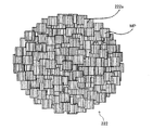
- FIG. 5 is an enlarged view schematically showing the configuration of still another example of the positive electrode active material particles of the present invention shown in FIG. 2.
- FIG. 5 shows typically an example of the manufacturing method of the positive electrode active material particle which concerns on one Embodiment of this invention shown by (i), FIG. 5, and FIG. 6 in FIG. 14 is a SEM (scanning electron microscope) photograph of positive electrode active material particles of Example 13.
- FIG. 9 is a higher magnification SEM photograph of the particles of Example 13 shown in FIG.
- FIG. 4 is an enlarged view schematically showing the configuration of still another example of the positive electrode active material particles shown in FIG. 2.
- FIG. 1 is a cross-sectional view showing a schematic configuration of an embodiment of the lithium secondary battery of the present invention.
- a lithium secondary battery 1 according to this embodiment is a so-called liquid coin cell, and includes a positive electrode plate 2, a negative electrode plate 3, a separator 4, an electrolytic solution 5, and a battery case 6. It is equipped with.
- the positive electrode plate 2 is formed by laminating a positive electrode current collector 21 and a positive electrode active material layer 22.
- the negative electrode plate 3 is formed by laminating a negative electrode current collector 31 and a negative electrode active material layer 32.
- the lithium secondary battery 1 includes a positive electrode current collector 21, a positive electrode active material layer 22, a separator 4, a negative electrode layer 31, and a negative electrode current collector 32, which are stacked in this order. And an electrolyte solution 5 containing as an electrolyte in a battery case 6 (including a positive electrode side container 61, a negative electrode side container 62, and an insulating gasket 63) in a liquid-tight manner.
- portions other than the positive electrode active material layer 22 can be formed using various conventionally known materials.
- amorphous carbonaceous materials such as soft carbon and hard carbon
- highly graphitized carbon materials such as artificial graphite and natural graphite, acetylene black, and the like can be used.
- the negative electrode plate 3 is formed by coating the negative electrode material prepared using these negative electrode active materials on the negative electrode current collector 32 made of a metal foil or the like.
- organic solvent used in the non-aqueous electrolyte 5 examples include carbonate solvents such as ethylene carbonate (EC), diethyl carbonate (DEC), dimethyl carbonate (DMC), propylene carbonate (PC), ⁇ -butyrolactone, A single solvent such as tetrahydrofuran or acetonitrile, or a mixed solvent thereof is preferred.
- carbonate solvents such as ethylene carbonate (EC), diethyl carbonate (DEC), dimethyl carbonate (DMC), propylene carbonate (PC), ⁇ -butyrolactone
- EC ethylene carbonate
- DEC diethyl carbonate
- DMC dimethyl carbonate
- PC propylene carbonate
- ⁇ -butyrolactone A single solvent such as tetrahydrofuran or acetonitrile, or a mixed solvent thereof is preferred.
- Examples of the electrolyte contained in the electrolytic solution 5 include lithium complex fluorine compounds such as lithium hexafluorophosphate (LiPF 6 ) and lithium borofluoride (LiBF 4 ); lithium halides such as lithium perchlorate (LiClO 4 ); Etc. can be used.
- the electrolyte solution 5 is prepared by melt
- FIG. 2 is an enlarged cross-sectional view of the positive electrode plate 2 shown in FIG.
- the positive electrode active material layer 22 includes a binder 221, positive electrode active material particles 222 uniformly dispersed in the binder 221, and a conductive additive (carbon or the like). It is joined to the electric body 21. That is, the positive electrode plate 2 is obtained by mixing the positive electrode active material particles 222, polyvinylidene fluoride (PVDF) or the like as the binder 221 and acetylene black or the like as a conductive agent at a predetermined ratio. The positive electrode material is prepared and applied to the surface of the positive electrode current collector 21 made of a metal foil or the like.
- PVDF polyvinylidene fluoride
- the positive electrode active material particles 222 according to the present embodiment are fine particles having an average particle diameter of 1 to 100 ⁇ m, and have a substantially spherical shape or a substantially spheroid shape, specifically, an aspect ratio of 1.0 to 1.5 ( Preferably, it is formed to be 1.1 to 1.3).
- FIG. 3 is an enlarged view schematically showing an example of the positive electrode active material particle 222 shown in FIG. 2, and (ii) shows a conventional positive electrode active material particle 222 ′ as a comparative example. It is an enlarged view typically shown.
- the positive electrode active material particles 222 are composed of lithium-nickel composite oxide single crystal primary particles 222a having a layered rock salt structure (average particle diameter is 0.01 to 5 ⁇ m). Are secondary particles.
- the single crystal primary particles 222a have the (003) plane indicated by “MP” in the drawing in-plane orientation (that is, the (003) plane is oriented so as to intersect the plate surface of the single crystal primary particles 222a). Is formed. Needless to say, all the (003) planes are parallel to each other in one single crystal primary particle 222a.
- the positive electrode active material particles 222 of the present embodiment have a high uniaxial orientation with a (003) plane. That is, in the positive electrode active material particles 222, a large number of single crystal primary particles 222a constituting the positive electrode active material particles 222 are arranged so that the orientations of the (003) planes are aligned with each other (the (003) planes are as parallel as possible to each other). Is provided). Specifically, the orientation of the (003) plane is such that the orientation ratio of the (003) plane is 50% or more (with respect to the total number of the plurality of single crystal primary particles 222a included in the positive electrode active material particles 222). The positive electrode active material particles 222 are formed so that the ratio of the single crystal primary particles 222a having the same is 50% or more.
- the (003) plane is substantially uniaxially oriented (specifically, the orientation ratio of the (003) plane is 50. %),
- the lithium ion diffusion resistance between the single crystal primary particles 222a is reduced, and the lithium ion conductivity and the electron conductivity are improved.
- the charge / discharge characteristic (especially rate characteristic) of the lithium secondary battery 1 can be remarkably improved.
- microcracks that normally occur between the single crystal primary particles 222a (ie, at grain boundaries) due to volume expansion and contraction due to repeated charge and discharge are parallel to the (003) plane that is the lithium ion diffusion plane and the electron conduction plane ( That is, it becomes easy to enter in a direction that does not affect the diffusion of lithium ions and does not affect the electron conductivity. For this reason, it is possible to suppress deterioration of charge / discharge characteristics (particularly rate characteristics) due to repeated charge / discharge cycles.
- the positive electrode active material particle 222 of the present embodiment which is a secondary particle formed by aggregating a plurality of single crystal primary particles 222a of a lithium-nickel composite oxide having a layered rock salt structure, due to the above-described orientation, Polarization at the end of discharge is greatly improved. Therefore, according to the positive electrode active material particle 222 of the present embodiment, when using a nickel-cobalt-aluminum-based positive electrode active material, higher output (higher capacity at the time of high-rate discharge), and polarization at the end of discharge. Suppression of substantial capacity reduction due to the improvement and good cycle characteristics are realized.
- the orientation ratio of the (003) plane is preferably 70% or more, and particularly preferably 90%.
- the ratio at which the in-plane directions of the (003) plane are parallel to each other in the number of single crystal primary particles 222a included in the positive electrode active material particles 222 as the orientation ratio is higher. Can be said to increase. For this reason, as the orientation ratio is higher, the diffusion distance of lithium ions is shortened and the diffusion resistance of lithium ions is reduced as described above, so that the charge / discharge characteristics of the lithium secondary battery 1 are significantly improved.
- the purpose is to improve durability, increase capacity, and improve safety. As described above, even when the average particle diameter of the positive electrode active material particles 222 is increased, it is possible to maintain high rate characteristics by increasing the orientation ratio.
- the average particle diameter of the single crystal primary particles 222a is 0.01 to 5 ⁇ m, preferably 0.05 to 3 ⁇ m, and more preferably 0.05 to 1.5 ⁇ m.
- the crystallinity of the single crystal primary particles 222a is ensured by setting the average particle diameter of the single crystal primary particles 222a within the above range. If the average particle diameter of the single crystal primary particles 222a is less than 0.1 ⁇ m, the crystallinity of the single crystal primary particles 222a may be reduced, and the output characteristics of the lithium secondary battery 1 may be reduced. However, in the positive electrode active material of the present invention, even if the average particle size of the single crystal primary particles 222a is 0.1 to 0.01 ⁇ m, no significant reduction in output characteristics is observed.
- the positive electrode active material particles 222 as the secondary particles The occurrence of cracks is suppressed as much as possible.
- the average particle diameter of the single crystal primary particles 222a is more than 5 ⁇ m, the positive electrode active material particles as the secondary particles due to the stress generated when the volume of the single crystal primary particles 222a expands or contracts during charging and discharging. 222 may crack.
- the average particle diameter of the positive electrode active material particles 222 as secondary particles is 1 to 100 ⁇ m, preferably 2 to 70 ⁇ m, and more preferably 3 to 50 ⁇ m.
- the average particle diameter of the positive electrode active material particles 222 is 1 to 100 ⁇ m, preferably 2 to 70 ⁇ m, and more preferably 3 to 50 ⁇ m.
- the filling property of the positive electrode active material in the positive electrode active material particles 222 is ensured (the filling rate is improved).
- a flat electrode surface can be formed while maintaining the output characteristics of the lithium secondary battery 1.
- the average particle diameter of the positive electrode active material particles 222 is less than 1 ⁇ m, the filling rate of the positive electrode active material may be reduced.
- the average particle diameter of the positive electrode active material particles 222 exceeds 100 ⁇ m, the output characteristics of the lithium secondary battery 1 may be degraded, and the flatness of the electrode surface may be degraded.
- the distribution of the average particle diameter of the positive electrode active material particles 222 may be sharp, broad, or have a plurality of peaks. For example, when the average particle size distribution of the positive electrode active material particles 222 is not sharp, the packing density of the positive electrode active material in the positive electrode active material layer 22 is increased, or the adhesion between the positive electrode active material layer 22 and the positive electrode current collector 21 is increased. Can be increased. Thereby, rate characteristics and cycle characteristics can be further improved.
- the aspect ratio of the positive electrode active material particles 222 is 1.0 or more and less than 2.0, and preferably 1.1 to 1.5. Even if the packing density of the positive electrode active material in the positive electrode active material layer 22 is increased by setting the aspect ratio of the positive electrode active material particles 222 within this range, the electrolysis impregnated in the positive electrode active material layer 22 is achieved. It is possible to form an appropriate gap between the positive electrode active material particles 222 so as to ensure a path through which lithium ions in the liquid 5 diffuse in the thickness direction of the positive electrode active material layer 22. Thereby, the output characteristics of the lithium secondary battery 1 can be further improved.
- the positive electrode active material particles 222 are arranged in the plate surface direction of the positive electrode current collector 21 and the major axis direction of the particles when the positive electrode active material layer 22 is formed. It becomes easy to fill in a state in which and are arranged in parallel. Then, the diffusion path of the lithium ions in the electrolyte solution 5 impregnated in the positive electrode active material layer 22 in the thickness direction of the positive electrode active material layer 22 becomes long. For this reason, the output characteristics of the lithium secondary battery 1 may deteriorate.
- the aspect ratio of the single crystal primary particles 222a is preferably 1.0 or more and 2.0 or less, and more preferably 1.1 or more and 1.5 or less. The reason for this is as follows.
- the single crystal primary particles of the positive electrode active material are likely to grow in an orientation parallel to the (003) plane, which is a conductive surface for lithium ions and electrons. For this reason, generally, in such single crystal primary particles, the aspect ratio tends to be large (the particles have a flat shape). At the same time, many (003) planes, which are crystal planes from which lithium ions and electrons hardly enter and exit, are exposed on the surface.
- the aspect ratio of the single crystal primary particles 222a to 2.0 or less, a surface where lithium ions and electrons easily enter and exit at the contact portion between the adjacent single crystal primary particles 222a ( That is, the contact between the surfaces other than the (003) surface can be sufficiently ensured, and therefore, the lithium ion conductivity and the electron conductivity in the positive electrode active material particles 222 as the secondary particles are favorably ensured. In particular, this effect is remarkable when the crystal plane orientation of the positive electrode active material particles 222 is high.
- the positive electrode active material particles 222 are densely formed (that is, in a state where a large number of single crystal primary particles 222a are densely packed without gaps), the positive electrode active material layers 22 in the positive electrode active material layer 22 are formed.
- the packing density of the substance can be increased, which is advantageous for increasing the capacity.
- the electrolyte solution and the conductive material can be contained in the gap 222b.
- rate characteristics can be improved while maintaining a high capacity.
- the stress at the time of charging / discharging can also be relieved and the capacity deterioration (cycle characteristic) by repetition of charging / discharging can also be improved.
- the degree of introduction of the void 222b can be defined by “void ratio”, “average pore diameter”, and “open pore ratio”.
- FIG. 6 is a schematic view showing a part of the positive electrode active material particles 222 shown in FIG. 5 in an enlarged manner.
- (Ii) in FIG. 6 is a schematic diagram showing an enlarged part of a conventional positive electrode active material particle 222 ′ as a comparative example.
- the (003) plane (see “MP” in the drawing) of the single crystal primary particles 222a constituting the positive electrode active material particles 222 including the voids 222b is in a specific direction.
- the resistance (grain boundary resistance) at the grain boundary GB is reduced.
- the reduction of the grain boundary resistance and the void 222b containing the electrolytic solution and the conductive material maximize the lithium ion conductivity and the electron conductivity in the positive electrode active material particle 222 including the void 222b.
- voids 222b are included in conventional positive electrode active material particles 222 ′ in which the (003) plane of the single crystal primary particles 222a is not oriented in a specific direction.
- the electrolyte solution and the conductive material penetrate into the gap 222b, the lithium ion conductivity and the electron conductivity are reduced because the conduction path of lithium ions and electrons becomes narrow.
- the narrowest part (neck part) of the conduction path is often the grain boundary GB, and when the grain boundary resistance is high, the decrease in conductivity becomes significant (note that the grain boundary resistance is actually Although not observed, an image showing the level of the grain boundary resistance is shown at the grain boundary GB in the figure.
- “Voidage” is the volume ratio of voids 222 b (pores: including open pores and closed pores) in the positive electrode active material particles 222.
- “Porosity” is sometimes referred to as “porosity”. This “porosity” can be calculated from, for example, the bulk density and the true density. Specifically, the relative density is obtained by dividing the bulk density obtained by the Archimedes method by the true density obtained using a pycnometer. Subsequently, the porosity is calculated
- the porosity is preferably 60% or less, more preferably 50% or less, and even more preferably 40% or less.
- Average pore diameter is the average value of the diameters of the pores in the positive electrode active material particles 222.
- the “diameter” is typically a diameter of the sphere when the pore is assumed to be a sphere having the same volume or the same cross-sectional area.
- the “average value” is suitably calculated based on the number.
- the average pore diameter can be determined by a known method such as image processing of a cross-sectional SEM photograph or mercury intrusion method. More specifically, the average pore diameter can be measured by a mercury intrusion method using a mercury intrusion pore distribution measuring device (manufactured by Shimadzu Corporation, device name “Autopore IV9510”).
- the average pore diameter is preferably 0.01 to 5 ⁇ m, more preferably 0.05 to 4.5 ⁇ m, and still more preferably 0.1 to 4.0 ⁇ m.
- the average pore diameter is more than 5 ⁇ m, relatively large pores are generated. When such large pores exist, the amount per volume of the positive electrode active material that contributes to charge / discharge decreases. In addition, stress concentration is likely to occur locally in such large pores, and it is difficult to obtain the effect of releasing stress uniformly inside.
- the average pore diameter is less than 0.01 ⁇ m, it is difficult to contain the conductive material and the electrolyte, and the stress releasing effect by the pores is insufficient. For this reason, the effect of improving rate characteristics and cycle characteristics while maintaining a high capacity may not be expected.
- the “open pore ratio” is a volume ratio of open pores to the whole voids (pores) included in the positive electrode active material particles 222.
- Open pores refer to pores 222 b (pores) included in the positive electrode active material particles 222 that communicate with the outside of the positive electrode active material particles 222.
- This “open pore ratio” can be calculated from, for example, the sum of the open pores and closed pores obtained from the bulk density and the closed pores obtained from the apparent density.
- the parameters used for calculating the “open pore ratio” can be measured using Archimedes method or the like.
- the inner wall surface (surface) of the positive electrode active material particles 222 constituting the open pores functions well as a surface through which lithium ions enter and exit. Therefore, it is preferable to set the open pore ratio to 50% or more from the viewpoint of improving rate characteristics as compared with a case where the ratio of closed pores existing as simple pores (portions that do not contribute to charge / discharge) is large.
- the open pore ratio for example, 70% or more
- the rate characteristics are further improved while maintaining a high capacity, and further the cycle Properties are also improved.
- a particulate or fibrous substance that is decomposed (evaporated or carbonized) in the pre-baking step can be suitably used.
- particulate or fibrous materials of organic synthetic resins such as theobromine, nylon, graphite, phenol resin, polymethyl methacrylate, polyethylene, polyethylene terephthalate, and foamable resin can be suitably used.
- Other compounds may be present in the gap 222b.
- an electrolyte, a conductive material, other lithium ion positive electrode active materials having excellent rate characteristics, positive electrode active materials having different particle diameters, and the like are present in the gap 222b, the rate characteristics and cycle characteristics are further improved.
- a method for causing the other compound to exist in the void 222b a method of applying the compound to the surface of the void forming material in advance and adjusting the firing conditions, or forming the positive electrode active material particles 222 is possible. There is a method of mixing a compound with raw material particles.
- the surface of the single crystal primary particles 222a or the positive electrode active material particles 222 may be coated with another material.
- the thermal stability and chemical stability of the material are improved, and the rate characteristics are improved.
- the coating material for example, the following materials can be used: chemically stable alumina, zirconia, fluorinated alumina, etc .; materials such as lithium cobaltate having excellent lithium diffusibility; Excellent carbon.
- the positive electrode active material particles 222 of this embodiment can be manufactured, for example, by a manufacturing method as described below.
- FIG. 7 is a diagram schematically showing an example of such a manufacturing method.
- raw material particles particles obtained by appropriately mixing particles of compounds such as Li, Co, Ni, Mn, and Al so that the composition of the positive electrode active material is LiMO 2 can be used. Specifically, for example, mixed particles ((Co, Ni, Mn) O x , (Co, Ni, Al) O x , (Co , Ni, Mn) OH x , (Co, Ni, Al) OH x , etc.). By molding these mixed particles and further reacting the obtained compact with the lithium compound, positive electrode active material particles having a predetermined composition can be obtained.
- a hydroxide having a composition such as (Co, Ni, Mn) OH x , (Co, Ni, Al) OH x , or the like as the raw material particles.
- a hydroxide has a shape of flat primary particles having a (001) plane on a flat surface, and the primary particles are easily oriented by a molding process described later.
- the (001) plane is a plane whose orientation is inherited as the (003) plane in the positive electrode active material having a predetermined composition by reacting with the lithium compound. For this reason, by using such plate-like raw material particles, the (003) plane in the positive electrode active material particles 222 can be easily oriented.
- a large amount of lithium compound may be introduced into the raw material particles so that the lithium is in an excess of 0.5 to 40 mol%. .
- 0.001 to 30% by mass of low melting point oxide (such as bismuth oxide), low melting point glass (such as borosilicate glass), lithium fluoride, or lithium chloride is added to the raw material particles. May be.
- a void forming material for forming voids having desired “porosity”, “average pore diameter”, and “open pore ratio” may be added.
- the prepared raw material particles are molded into a sheet-like self-supporting molded body having a thickness of 100 ⁇ m or less.
- self-supporting in the “self-supporting molded body” is synonymous with “independent” in the “independent sheet” described later. That is, the “self-supporting molded body” is, as a rule, capable of maintaining the shape of a sheet-shaped molded body by itself. However, even if it cannot maintain the shape of a sheet-like molded body by itself at a certain time, it is once formed into a sheet by pasting or forming a film on some substrate. What has been peeled off from the substrate before or after firing is also included in the “self-supporting molded body”.
- the extruded sheet is a “self-supported molded body” immediately after molding.
- the slurry coating film cannot be handled alone before drying, but becomes a “self-supporting molded body” after drying and peeling from the substrate.
- sheet shape includes plate shape, flake shape, scale shape, and the like.
- the molding method is not particularly limited as long as the raw material particles are filled in the molded body with the same crystal orientation.
- a slurry containing raw material particles by using a doctor blade method, it is possible to obtain a (self-supporting sheet-like) molded body in which the raw material particles are filled in the same crystal orientation.
- a doctor blade method when using the doctor blade method, first, a slurry S (see (i) in FIG. 7) containing raw material particles 701 on a flexible substrate (for example, an organic polymer plate such as a PET film) is used.
- the applied slurry S is dried and solidified to form a dry film.
- the dry film is peeled from the above-described substrate to obtain a shaped body 702 in which the raw material particles 701 are oriented (filled with the same crystal orientation) (see (ii) in FIG. 7).
- the above-described molded body 702 can be obtained by scraping off a slurry obtained by applying a slurry containing raw material particles on a heated drum using a drum dryer and drying the slurry. Furthermore, the above-mentioned molded object 702 can be obtained by scraping with a scraper what applied and dried the slurry containing raw material particles on the heated disk surface using a disk dryer. Moreover, the above-mentioned molded object 702 can be obtained by extrusion molding using clay containing raw material particles.
- a binder, a plasticizer, or the like may be appropriately added to the raw material particles dispersed in an appropriate dispersion medium.
- the kind and amount of the additive such as a binder are appropriately adjusted so that the packing density and orientation degree of the raw material particles at the time of molding or the shape of the pulverized product in the pulverization step described later can be controlled to a desired state.
- the kind and addition amount of a binder, a plasticizer, etc. can be adjusted suitably so that the softness
- the viscosity When using a slurry containing raw material particles, it is preferable to adjust the viscosity to be 0.5 to 5 Pa ⁇ s or to defoam under reduced pressure. Furthermore, when another compound is present in the voids, it is preferable to prepare a slurry containing this compound and raw material particles.
- the thickness of the molded body 702 is preferably 120 ⁇ m or less, and more preferably 100 ⁇ m or less. Moreover, it is preferable that the thickness of the molded object 702 is 1 micrometer or more. If the thickness of the molded body 702 is 1 ⁇ m or more, it becomes easy to produce a self-supporting sheet-shaped molded body. Note that the thickness of the formed body 702 is a direct factor that determines the average particle diameter of the positive electrode active material particles 222, and thus is appropriately set according to the use of the particles.
- the obtained formed body 702 is crushed so that the positive electrode active material particles 222 have a desired aspect ratio.
- the following can be used: a method of pressing the mesh with a spatula or the like; a method of crushing with a crusher having a weak crushing force such as a pin mill; Specifically, a method of feeding into an air classifier); swirling jet mill; pot crushing; barrel polishing;
- the process for spheroidizing the crushed material may be performed.
- the positive electrode active material particles 222 finally obtained have a substantially spherical shape or a substantially spheroid shape. Since the positive electrode active material particles 222 are substantially spherical or spheroid, the exposure of the lithium ion entrance / exit surface on the outer surface of the particles is increased, and the positive electrode active material filling rate in the positive electrode active material layer 22 is increased. As a result, the battery characteristics are improved.
- the following method can be used: a method of taking “corners” of the crushed particles by colliding the crushed particles with each other in an air stream (airflow classification, hybridization, etc.); Method of removing “corner” of crushed particles by colliding crushed particles with each other (method using hybrid mixer or high speed stirrer / mixer, barrel polishing, etc.); mechanochemical method; crushed particles by hot air Method of melting the surface of the.
- the spheronization treatment and crushing may be performed separately, but may be performed simultaneously. That is, for example, by using an airflow classifier, crushing and spheronization can be performed simultaneously.
- the molded body may be degreased or heat-treated (fired or temporarily fired) in advance.
- the molded body may be dried at a relatively high temperature at which the binder is denatured or decomposed.
- the raw material particles are plate-shaped (for example, when the raw material particles are hydroxide)
- the molded body before pulverization has many plate-shaped raw material particles arranged in parallel with the plate surface of the molded body. The internal structure looks like an agglomeration.
- the internal structure of the molded body before crushing and before firing (before lithium introduction) can be brought into a state in which an oxide having an isotropic shape is necked. It becomes easy to set the aspect ratio of the crushed material to 2 or less.
- the calcination temperature is preferably in the range of 600 to 1100 ° C. When the calcination temperature is less than 600 ° C., the above-described progress of necking becomes insufficient, and the molded body after the calcination becomes brittle, so that the particle size of the crushed material becomes too fine due to crushing.
- Such preliminary firing before crushing is a composition in which adverse effects such as phase separation are not easily caused by temporary firing (for example, nickel-cobalt-based, nickel-cobalt-aluminum-based, nickel-aluminum-based, etc.) containing nickel while containing manganese. It is particularly preferred to be carried out in a system that does not contain.
- the state in which the raw material particles (plate-shaped raw material particles) 701 are well oriented remains in the positive electrode active material precursor particles 703 that are the pulverized product obtained. (See (iii) in FIG. 7). That is, the positive electrode active material precursor particles 703 are raw material particle aggregates containing a large number of plate-like raw material particles 701, and these raw material particles 701 are formed so as to be substantially uniformly oriented.
- the positive active material precursor particles 704 that are the obtained crushed material have raw material particles ( The state in which the (plate-like raw material particles) 701 are oriented does not remain (see (iv) in FIG. 7). That is, the positive electrode active material precursor particles 704 have an internal structure corresponding to the heat-treated positive electrode active material precursor particles 703. Therefore, after positive electrode active material precursor particles 703 are obtained by pulverization without performing temporary firing, the positive electrode active material precursor particles 704 can be formed by temporary firing.
- those other than the desired aspect ratio (such as those that are not sufficiently crushed and remain in a large aspect ratio) and fine powder can be reused as raw materials.
- the aspect ratio is 1.0 or more and less than 2.0 (preferably 1.1 to 1) so that the positive electrode active material particles 222 have a desired aspect ratio and a desired (003) plane orientation state. 5), positive electrode active material precursor particles 703 or 704 having a predetermined internal structure are formed.
- the positive electrode active material precursor particles 703 or 704 those produced by a production method other than the above (1) to (3) can be used.
- a hydroxide having a composition such as (Co, Ni, Mn) OH x or (Co, Ni, Al) OH x obtained as follows, having an aspect ratio of 1.0 or more and 2
- particles having a substantially spherical shape and a desired (001) plane orientation state of less than 0.0 are also possible to use.
- Co, Ni, Mn, or Co is added to a reaction vessel in which hydroxide seed crystal particles having a composition such as (Co, Ni, Mn) OH x or (Co, Ni, Al) OH x are added in advance.
- An aqueous solution containing Ni, Al, a complexing agent, and an alkali metal hydroxide are supplied with continuous stirring, thereby producing Co, Ni, Mn, or a complex salt of Co, Ni, Al. .
- this complex salt by decomposing this complex salt with an alkali metal hydroxide, the crystal orientation ((Co, Ni, Mn) OH x or (Co, Ni, Al) OH x (001) is introduced around the seed crystal.
- Co, Ni, Mn, or Co, Ni, Al hydroxide is deposited so that the surface is aligned.
- a mixture before firing is obtained.
- a lithium compound lithium hydroxide, lithium carbonate, etc.
- the average particle size of the lithium compound is preferably 0.1 to 5 ⁇ m.
- the lithium compound can be easily handled from the viewpoint of hygroscopicity.
- the reactivity with a crushed material increases that the average particle diameter of a lithium compound is 5 micrometers or less. In order to increase the reactivity, it is possible to keep the amount of lithium excessive by 0.5 to 40 mol%.
- Firing main firing: introduction of lithium
- the positive electrode active material precursor particles 703 or 704 By firing the above-mentioned mixture before firing by an appropriate method, lithium is introduced into the positive electrode active material precursor particles 703 or 704, whereby the positive electrode active material particles 222 are obtained.
- firing can be performed by putting a sheath containing the mixture before firing in a furnace.
- synthesis of the positive electrode active material, and further, particle sintering and particle growth are performed.
- the (001) plane of the raw material particles is oriented in the compact (positive electrode active material precursor particles 703 or 704), the crystal orientation is inherited, so that a predetermined composition is obtained.
- the (003) plane can be favorably uniaxially oriented.
- the firing temperature is preferably 600 ° C to 1100 ° C. When the firing temperature is lower than 600 ° C., grain growth is insufficient and the orientation rate may be lowered. On the other hand, when the firing temperature is higher than 1100 ° C., the decomposition of the positive electrode active material and the volatilization of lithium progress, and the predetermined composition may not be realized.
- the firing time is preferably 1 to 50 hours. If the firing time is shorter than 1 hour, the orientation ratio may be lowered. On the other hand, if the firing time is longer than 50 hours, the energy consumed for firing may be too large.
- the firing atmosphere must be set appropriately so that decomposition does not proceed during firing.
- firing is preferably performed in an atmosphere having a high oxygen partial pressure.
- pulverization and classification (the above-mentioned pre-fired solution is appropriately performed). Since it is performed after crushing and classification, it may be referred to as “secondary crushing” or “secondary classification”). Or the above-mentioned crushing process may be performed after baking. That is, the crushing step (and classification step) may be performed only after firing.
- Orientation rate (%) Secondary particle powder was arranged on a glass substrate so that secondary particles might not overlap as much as possible.
- a sample for observation was prepared by polishing a powder obtained by copying this powder onto an adhesive tape and embedding it in a synthetic resin so that the plate surface or cross-section polished surface of the secondary particles can be observed.
- polishing was performed with a vibration type rotary polishing machine using colloidal silica (0.05 ⁇ m) as an abrasive.
- polishing was performed with a cross section polisher (CP).
- a histogram (angle distribution) of the number of particles with respect to the angle is output, and the angle at which the number of primary particles is maximum (peak value) is defined as the (003) plane inclination angle ⁇ with respect to the measurement surface of the secondary particles.
- the number of primary particles having a (003) plane within ⁇ ⁇ 10 degrees was calculated for the measured secondary particles.
- the orientation ratio of the (003) plane in the measured secondary particles was calculated. This was performed for 10 different secondary particles, and the average value was defined as the orientation ratio of the (003) plane.
- discharge capacity at 2C rate The measured value of the discharge capacity at the second cycle was defined as “discharge capacity at 2C rate”.
- the value obtained by dividing the “discharge capacity at the 2C rate” by the “discharge capacity at the 0.1C rate” was defined as the rate capacity maintenance rate.
- Nickel-cobalt-aluminum composition (Example 1) (1) Preparation of raw material particles and slurry Ni (OH) 2 powder (manufactured by Kojundo Chemical Laboratory Co., Ltd.), Co (so that the molar ratio of Ni, Co, Al in the mixture is 75: 20: 5 OH) 2 powder (manufactured by High-Purity Chemical Laboratory Co., Ltd.) and Al 2 O 3 .H 2 O (manufactured by SASOL) are weighed, and the weighed material is pulverized and mixed for 16 hours with a ball mill, whereby raw material particles A powder was prepared.
- a binder polyvinyl butyral: product number BM-2, manufactured by Sekisui Chemical Co., Ltd.
- a plasticizer DOP: Di (2-ethylhexyl) phthalate, manufactured by Kurokin Kasei Co., Ltd.
- a dispersant product name “Leodol SP-O30”, manufactured by Kao Corporation
- the mixture was defoamed by stirring under reduced pressure, and a slurry was prepared by adjusting the viscosity to 3 to 4 Pa ⁇ s (viscosity was measured using a Brookfield LVT viscometer). It was measured.).
- Firing step (lithium introduction step)
- the mixed powder described above is put into a crucible made of high-purity alumina and heat-treated at 750 ° C. for 12 hours in an oxygen atmosphere (0.1 MPa), so that Li (Ni 0.75 Co 0.2 Al 0 .05 ) O 2 powder was obtained.
- coin cell batteries were prepared as follows. By mixing the obtained Li (Ni 0.75 Co 0.2 Al 0.05 ) O 2 powder, acetylene black, and polyvinylidene fluoride (PVDF) so as to have a mass ratio of 75: 20: 5.
- a positive electrode material was prepared.
- a positive electrode active material layer was produced by press-molding 0.02 g of the prepared positive electrode material into a disk shape having a diameter of 20 mm at a pressure of 300 kg / cm 2 .
- a coin cell as shown in FIG. 1 was produced using the produced positive electrode active material layer.
- the electrolytic solution was prepared by dissolving LiPF 6 in an organic solvent in which ethylene carbonate (EC) and diethyl carbonate (DEC) were mixed at an equal volume ratio to a concentration of 1 mol / L.
- EC ethylene carbonate
- DEC diethyl carbonate
- Li (Ni) was prepared in the same manner as in Example 1, except that the opening diameter of the sieve (mesh) was 20 ⁇ m (Example 2) and 25 ⁇ m (Example 3).
- a 0.75 Co 0.2 Al 0.05 ) O 2 powder was prepared.
- Example 4 In “(2) Forming raw material particles”, the same method as in Example 1 except that the feed rate in the doctor blade method was set to 0.5 m / s (Example 4) and 5 m / s (Example 5). , Li (Ni 0.75 Co 0.2 Al 0.05 ) O 2 powder was prepared.
- NiO powder manufactured by Shodo Chemical Industry Co., Ltd.
- Co 3 O 4 powder manufactured by Shodo Chemical Industry Co., Ltd.
- Al 2 O 3 powder manufactured by Showa Denko KK
- Li (Ni 0.75 Co 0.2 Al 0.05 ) O 2 powder was prepared in the same manner as in Example 1 except that a sieve (mesh) having an opening diameter of 25 ⁇ m was used in “Crushing the body”. did.
- Example 13 With respect to the manufacturing method of Example 13 described above, the feeding speed at the time of tape molding, presence / absence of temporary firing, mesh opening diameter, presence / absence of spheronization treatment (when spheroidization treatment is not performed, the same as Example 1 described above)
- the powders of Examples 6 to 12, Example 14 and Comparative Example 4 were obtained (see Table 2).
- powders of Comparative Examples 2 and 3 were obtained by using spray drying instead of tape molding (see Table 2).
- Powder molding by spray drying was performed as follows: using a spray dryer (manufactured by Sakamoto Giken Co., Ltd .: turning type TSR-3W), liquid amount 40 g / min, inlet temperature 200 ° C., atomizer rotation speed 13000 rpm. Under conditions, spherical granules were obtained.
- Example 6 to 14 and Comparative Examples 2 to 4 Evaluation was performed in the same manner as in Example 1 and the like.
- the aspect ratios of the particles before firing (precursor particles) in Examples 6 to 14 and Comparative Examples 2 to 4 were determined by the method described above.
- the evaluation batteries used for the battery characteristics evaluation were prepared in the same manner as in Example 1 except for the following.
- Li (Ni 0.8 Co 0.15 Al 0.05 ) O 2 powder, acetylene black, and polyvinylidene fluoride (PVDF) were mixed at a mass ratio of 90: 5: 5, and N
- a positive electrode active material paste was prepared by dispersing in -methyl-2-pyrrolidone. This paste was applied on an aluminum foil having a thickness of 20 ⁇ m as a positive electrode current collector so as to have a uniform thickness (thickness after drying: 50 ⁇ m), and punched out into a disk shape having a diameter of 14 mm from the dried sheet.
- a positive electrode plate was produced by pressing the product at a pressure of 2000 kg / cm 2 .
- a coin cell as shown in FIG. 1 was produced using the produced positive electrode plate.
- Example 7 when comparing Examples 6 to 14, the rate characteristic of Example 7 that performed the spheroidizing process was higher than that of Example 6 that did not perform the spheronizing process. Similarly, higher rate characteristics were obtained in Example 9 in which the spheronization process was performed than in Example 8 in which the spheronization process was not performed.
- the relationship between Examples 10 and 11 and Examples 12 and 13 was the same. Further, when Examples 7, 8, 11 and 12 using the same mesh were examined, the aspect ratio of the particles was closer to 1 and the rate characteristics were better when pre-baked (Examples 12 and 13). It became good.
- FIG. 8 the SEM photograph of the positive electrode active material particle of Example 13 is shown.
- FIG. 9 shows a higher magnification SEM photograph of the particles of the example (specifically, example 13).
- FIG. 10 shows a graph of discharge characteristics when the positive electrode active material particles of the examples and comparative examples are used.
- the solid line indicates the case where the particles of Example 13 are used
- the alternate long and short dash line indicates the case where the particles of Comparative Example 2 are used.
- a high voltage is satisfactorily maintained even immediately before the end of discharge. This is considered to be because the internal resistance in the positive electrode is reduced when the particles of the example are used.
- the ratio P of the discharge capacity when the discharge voltage is 3.5 V to the discharge capacity when the discharge voltage reaches 3 V is used as an index to determine the degree of polarization. evaluated. The closer this ratio is to 1, the smaller the polarization.
- Example 13 orientation
- Comparative Example 2 non-orientation
- the particle size and particle shape were almost the same and only the orientation state was different.
- the test temperature was set to 25 ° C.
- Cycle charge / discharge was performed.
- As an index of cycle characteristics a change in the rate capacity retention rate (same as in Example 1, 2C / 0.1C) in the battery before and after 50 cycles of charge / discharge was measured.
- Comparative Example 2 85% decreased to 74% before and after cycle charge / discharge, whereas in Example 13, the decrease was only from 95% to 90%.
- the configuration of the lithium secondary battery 1 to which the present invention is applied is not limited to the configuration described above.
- the present invention is not limited to the specific battery configuration as described above. That is, for example, as shown in FIG. 11, the present invention can also be suitably applied to a cylindrical lithium secondary battery 1 wound around a winding core 7.
- the present invention is not limited to a so-called liquid battery configuration. That is, for example, a gel polymer electrolyte or a polymer electrolyte can be used as the electrolyte.
- the orientation of the surface layer portion of the positive electrode active material particles 222 may be lower than the inside.
- the single crystal primary particles 222a are also formed in a region having a (003) plane that is difficult for lithium ions and electrons to enter and exit and having a widely exposed surface (see a region surrounded by an ellipse in a broken line in the figure). Lithium ions easily enter and exit from the outer electrolyte, thereby improving rate characteristics.
- Such a surface layer can be formed, for example, by reattaching the fine powder generated during the crushing or spheronizing treatment to the particles (this can be achieved by appropriately adjusting the conditions of the crushing or spheroidizing treatment). Becomes).
- Such an intragranular microstructure is, for example, an EBSD (electron backscattering diffraction image) in SEM observation of a cross section of a secondary particle (processed by a cross section polisher (CP), a focused ion beam (FIB), or the like). Method) and crystal orientation analysis in TEM observation.
- EBSD electron backscattering diffraction image
- CP cross section polisher
- FIB focused ion beam
- the present invention is not limited to the specific manufacturing method described above. That is, for example, the molding method is not limited to the above-described method. Moreover, the above-mentioned baking (lithium introduction) process can be skipped by selecting the raw material before shaping
- the positive electrode in which the raw material particles 701 are oriented (filled with the same crystal orientation) by applying a magnetic field during molding, etc.
- active material precursor particles 703 or positive electrode active material precursor particles 704 may be obtained. Therefore, the present invention is not limited to the case where hydroxide is used as the raw material particles.
- the positive electrode active material precursor particles of the present invention are provided to the market in a state containing a lithium compound (including internal addition and / or external addition of the lithium compound to the particle) and in a state mixed with the lithium compound. Can be done.
- the particles containing the lithium compound and the particles mixed with the lithium compound may be referred to as “positive electrode active material precursor particles that become the positive electrode active material particles of the lithium secondary battery by heat treatment”. It goes without saying that these can also be the subject of the present invention.
Abstract
Provided are cathode active material particles that are for a lithium secondary battery and that are formed as secondary particles resulting from the aggregation of a plurality of monocrystalline primary particles of a lithium-nickel composite oxide having a layered halite structure. The primary particles have an average particle size of 0.01-5 μm, and the secondary particles have an aspect ratio, which is the value of dividing the major axis diameter by the minor axis diameter, of at least 1.0 and less than 2, an average particle size of 1-100 μm, and a (003) plane that is essentially uniaxial in orientation. By means of such a configuration, it is possible to further improve battery characteristics, particularly high-rate charging/discharging characteristics and cycling characteristics.
Description
本発明は、リチウム二次電池(リチウムイオン二次電池と称されることもある)、該電池の正極活物質層に含有される正極活物質粒子、及びリチウムを導入することにより前記正極活物質粒子となる正極活物質前駆体粒子に関する。特に、本発明は、正極活物質としてリチウム-ニッケル系(以下、単に「ニッケル系」と称する。)複合酸化物を用いた場合に関する。
The present invention provides a lithium secondary battery (sometimes referred to as a lithium ion secondary battery), positive electrode active material particles contained in a positive electrode active material layer of the battery, and the positive electrode active material by introducing lithium. The present invention relates to positive electrode active material precursor particles to be particles. In particular, the present invention relates to the case where a lithium-nickel (hereinafter simply referred to as “nickel”) composite oxide is used as the positive electrode active material.
リチウム二次電池の正極材料として、いわゆるα-NaFeO2型の層状岩塩構造を有する正極活物質が広く知られている。この種の正極活物質としては、従来、主として、コバルト系(リチウム以外の遷移金属元素としてコバルトが主として含まれるものであって典型的にはLiCoO2)が用いられてきた(例えば、特開2003-132887号公報等参照)。
As a positive electrode material for a lithium secondary battery, a positive electrode active material having a so-called α-NaFeO 2 type layered rock salt structure is widely known. As this type of positive electrode active material, conventionally, cobalt-based materials (which typically contain cobalt as a transition metal element other than lithium and typically LiCoO 2 ) have been used (for example, Japanese Patent Laid-Open No. 2003-2003). -Ref.
しかしながら、近年では、高価で価格変動の激しいコバルトの使用量を低減させるために、例えば、ニッケル系(リチウム以外の遷移金属元素としてニッケルが主として含まれるものであって典型的にはLiNiO2;特に、ニッケル-コバルト系やニッケル-コバルト-アルミニウム系(例えば、特開2006-127955号公報等参照)等の多成分系)等の正極活物質も用いられるようになってきている。
However, in recent years, in order to reduce the amount of expensive and drastic cobalt fluctuations, for example, nickel-based materials (which typically contain nickel as a transition metal element other than lithium and typically LiNiO 2 ; Cathode active materials such as nickel-cobalt and nickel-cobalt-aluminum (for example, multi-component systems such as Japanese Patent Application Laid-Open No. 2006-127955) have also been used.
この種の正極活物質においては、(003)面以外の結晶面(リチウムイオン出入り面:例えば、(101)面や(104)面)で、リチウムイオン(Li+)の出入りが生じる。かかるリチウムイオンの出入りによって、リチウム二次電池の充放電動作が行われる。この点、正極活物質における、電解質と接触する表面(外表面)に、上述のリチウムイオン出入り面をより多く露出させることで、リチウム二次電池の電池特性が向上することが知られている(例えば、国際公開第2010/074304号等参照)。
In this type of positive electrode active material, lithium ions (Li + ) enter and exit on crystal planes other than the (003) plane (lithium ion entrance / exit surfaces: (101) plane or (104) plane, for example). The charging / discharging operation of the lithium secondary battery is performed by the entry and exit of the lithium ions. In this regard, it is known that the battery characteristics of the lithium secondary battery are improved by exposing more of the above-described lithium ion entrance / exit surfaces to the surface (outer surface) in contact with the electrolyte in the positive electrode active material ( For example, see International Publication No. 2010/074304).
なお、正極活物質内部のリチウムイオンの拡散は、(003)面の面内方向(すなわち(003)面と平行な方向)で行われることが知られている。
It is known that the diffusion of lithium ions inside the positive electrode active material is performed in the in-plane direction of the (003) plane (that is, the direction parallel to the (003) plane).
リチウム二次電池において、電池特性、特にハイレートでの充放電特性(以下、単に「レート特性」と称する。)及びサイクル特性を、よりいっそう向上することが求められている。本発明は、かかる課題に鑑みてなされたものである。
In lithium secondary batteries, it is required to further improve battery characteristics, particularly high rate charge / discharge characteristics (hereinafter simply referred to as “rate characteristics”) and cycle characteristics. The present invention has been made in view of such problems.
本発明の発明者らは、上記課題を解決すべく鋭意検討した結果、層状岩塩構造を有するリチウム-ニッケル系複合酸化物を含有する正極活物質粒子における(003)面を実質的に一軸配向させること(具体的には、前記正極活物質粒子を構成する多数の単結晶一次粒子が、それぞれの(003)面が可能な限り互いに平行になるように設けられること)によって、上記課題を解決することが可能であることを見出し、本発明を完成するに至った。
As a result of intensive studies to solve the above-mentioned problems, the inventors of the present invention substantially (uniaxially) orient the (003) plane in the positive electrode active material particles containing a lithium-nickel composite oxide having a layered rock salt structure. (Specifically, a large number of single crystal primary particles constituting the positive electrode active material particles are provided so that their (003) planes are as parallel as possible to each other), thereby solving the above-mentioned problem. As a result, the present invention has been completed.
本発明の一側面における特徴は、
・長軸径を短軸径で除した値であるアスペクト比が1.0以上2未満(好ましくは1.1~1.5)であり、
・リチウム導入後の前記正極活物質粒子における(003)面が実質的に一軸配向するように形成された
正極活物質前駆体粒子(リチウムを導入することにより、層状岩塩構造を有するリチウム-ニッケル系複合酸化物を含有する正極活物質粒子となる粒子)を提供することにある。 In one aspect of the present invention,
The aspect ratio, which is a value obtained by dividing the major axis diameter by the minor axis diameter, is 1.0 or more and less than 2 (preferably 1.1 to 1.5),
Positive electrode active material precursor particles formed so that the (003) plane of the positive electrode active material particles after lithium introduction is substantially uniaxially oriented (lithium-nickel system having a layered rock salt structure by introducing lithium The object of the present invention is to provide particles that become positive electrode active material particles containing a composite oxide.
典型的には、前記正極活物質前駆体粒子(以下、単に「前駆体粒子」と称することがある。)は、リチウム導入後の前記正極活物質粒子における(003)面の配向率が50%以上(好ましくは70%以上)となるように形成されている。
Typically, the positive electrode active material precursor particles (hereinafter sometimes simply referred to as “precursor particles”) have a (003) plane orientation ratio of 50% in the positive electrode active material particles after lithium introduction. It is formed so that it becomes more (preferably 70% or more).
具体的には、前記正極活物質前駆体粒子は、リチウム以外の遷移金属元素の化合物を主成分とする扁平な板状原料粒子を多数含有する原料粒子集合体であって、前記板状原料粒子が実質的に一様に配向するように形成されている。あるいは、前記正極活物質前駆体粒子は、前記板状原料粒子を実質的に一様に配向した状態で含有する前記原料粒子集合体を、熱処理したものである。
Specifically, the positive electrode active material precursor particles are raw material particle aggregates containing a large number of flat plate-like raw material particles mainly composed of a compound of a transition metal element other than lithium, and the plate-like raw material particles Are formed so as to be substantially uniformly oriented. Or the said positive electrode active material precursor particle | grains heat-process the said raw material particle aggregate containing the said plate-shaped raw material particle in the state orientated substantially uniformly.
本発明の他の一側面における特徴は、層状岩塩構造を有するリチウム-ニッケル系複合酸化物の単結晶一次粒子が複数集合してなる二次粒子として形成された、前記正極活物質粒子であって、以下の構成を有するものを提供することにある。
・前記一次粒子の平均粒子径は、0.01~5μmである。
・前記二次粒子は、長軸径を短軸径で除した値であるアスペクト比が1.0以上2未満(好ましくは1.1~1.5)であり、平均粒子径が1~100μmであり、(003)面が実質的に一軸配向している。 In another aspect of the present invention, the positive electrode active material particles are formed as secondary particles formed by aggregating a plurality of single crystal primary particles of a lithium-nickel composite oxide having a layered rock salt structure. An object of the present invention is to provide a device having the following configuration.
The average particle diameter of the primary particles is 0.01 to 5 μm.
The secondary particles have an aspect ratio that is a value obtained by dividing a major axis diameter by a minor axis diameter of 1.0 to less than 2 (preferably 1.1 to 1.5), and an average particle diameter of 1 to 100 μm. The (003) plane is substantially uniaxially oriented.
典型的には、(003)面の配向率が50%以上(好ましくは70%以上)となるように、前記正極活物質粒子(前記二次粒子)が形成されている。
Typically, the positive electrode active material particles (secondary particles) are formed so that the orientation ratio of the (003) plane is 50% or more (preferably 70% or more).
本発明のさらに他の一側面における特徴は、上記の構成を有する正極活物質粒子を含有した正極活物質層を含む正極と、負極活物質層を含む負極と、を備えたリチウム二次電池を提供することにある。
According to still another aspect of the present invention, there is provided a lithium secondary battery including a positive electrode including a positive electrode active material layer containing positive electrode active material particles having the above-described configuration, and a negative electrode including a negative electrode active material layer. It is to provide.
ここで、「層状岩塩構造」とは、リチウム以外の遷移金属層とリチウム層とが酸素原子の層を挟んで交互に積層された結晶構造、すなわち、リチウム以外の遷移金属のイオン層とリチウムイオン層とが酸化物イオンを挟んで交互に積層された結晶構造(典型的にはα-NaFeO2型構造:立方晶岩塩型構造の[111]軸方向に遷移金属とリチウムとが規則配列した構造)をいう。
Here, the “layered rock salt structure” means a crystal structure in which transition metal layers other than lithium and lithium layers are alternately stacked with an oxygen atom layer interposed therebetween, that is, an ion layer of transition metal other than lithium and lithium ions. Crystal structure in which layers are alternately stacked with oxide ions (typically α-NaFeO 2 type structure: a structure in which transition metal and lithium are regularly arranged in the [111] axis direction of cubic rock salt type structure ).
層状岩塩構造を有するリチウム-ニッケル系複合酸化物としては、典型的にはニッケル酸リチウム(LiNiO2)を用いることができるが、ニッケルを他の遷移金属元素で置換したものを用いることも可能である。具体的には、ニッケル・マンガン酸リチウム、ニッケル・コバルト酸リチウム、コバルト・ニッケル・マンガン酸リチウム、等が挙げられる。さらに、これらの材料に、Mg,Al,Si,Ca,Ti,V,Cr,Fe,Cu,Zn,Ga,Ge,Sr,Y,Zr,Nb,Mo,Ag,Sn,Sb,Te,Ba,Bi等の元素が1種以上含まれていてもよい。
As the lithium-nickel composite oxide having a layered rock salt structure, lithium nickelate (LiNiO 2 ) can be typically used, but nickel substituted with other transition metal elements can also be used. is there. Specific examples include nickel / lithium manganate, nickel / lithium cobaltate, cobalt / nickel / lithium manganate, and the like. Further, these materials include Mg, Al, Si, Ca, Ti, V, Cr, Fe, Cu, Zn, Ga, Ge, Sr, Y, Zr, Nb, Mo, Ag, Sn, Sb, Te, Ba. One or more elements such as Bi and Bi may be contained.
すなわち、本発明にて特に好適に用いられるニッケル-コバルト-アルミニウム系の正極活物質は、以下の一般式で表される組成を有している。
一般式:Lip(Nix,Coy,Alz)O2
(上記一般式中、0.9≦p≦1.3,0.6<x≦0.9,0.05≦y≦0.25,0≦z≦0.2,x+y+z=1) That is, the nickel-cobalt-aluminum positive electrode active material particularly preferably used in the present invention has a composition represented by the following general formula.
General formula: Li p (Ni x, Co y, Al z) O 2
(In the above general formula, 0.9 ≦ p ≦ 1.3, 0.6 <x ≦ 0.9, 0.05 ≦ y ≦ 0.25, 0 ≦ z ≦ 0.2, x + y + z = 1)
pの好ましい範囲は0.9≦p≦1.3であり、より好ましい範囲は1.0≦p≦1.1である。pが0.9未満であると、放電容量が低下するので、好ましくない。また、pが1.3以上であると、放電容量が低下したり、充電時の電池内部のガス発生が多くなったりするので、好ましくない。
The preferable range of p is 0.9 ≦ p ≦ 1.3, and the more preferable range is 1.0 ≦ p ≦ 1.1. If p is less than 0.9, the discharge capacity decreases, which is not preferable. Moreover, when p is 1.3 or more, the discharge capacity is reduced, or gas generation inside the battery during charging is increased, which is not preferable.
xが0.6未満であると、放電容量が低下するので、好ましくない。また、xが0.9を超えると、安定性が低下するので、好ましくない。xは、好ましくは、0.7~0.85である。
X It is not preferable that x is less than 0.6, since the discharge capacity decreases. Further, when x exceeds 0.9, the stability is lowered, which is not preferable. x is preferably 0.7 to 0.85.
yが0.05以下であると、結晶構造が不安定になるので、好ましくない。また、yが0.25を超えると、放電容量が低下するので、好ましくない。yは、好ましくは、0.10~0.20である。
If y is 0.05 or less, the crystal structure becomes unstable, which is not preferable. On the other hand, if y exceeds 0.25, the discharge capacity decreases, which is not preferable. y is preferably 0.10 to 0.20.
zが0.2を超えると、放電容量が低下するので、好ましくない。zは、好ましくは、0.02~0.1である。
When z exceeds 0.2, the discharge capacity decreases, which is not preferable. z is preferably 0.02 to 0.1.
「一次粒子」とは、凝集体を形成せず単独で存在する粒子をいう。特に、「単結晶一次粒子」とは、内部に結晶粒界を含まない一次粒子をいう。これらに対し、一次粒子が凝集したものや、単結晶一次粒子が複数(多数)集合したものを、「二次粒子」という。
“Primary particles” refers to particles that do not form aggregates and exist alone. In particular, “single crystal primary particles” refer to primary particles that do not contain grain boundaries inside. On the other hand, those in which primary particles are aggregated and those in which a plurality (large number) of single-crystal primary particles are aggregated are referred to as “secondary particles”.
「アスペクト比」は、粒子の長手方向の径(長軸径)と短手方向の径(短軸径)との比である。この値が1に近いほど、粒子は球状に近い形状であるといえる。なお、前記一次粒子のアスペクト比は、1.0以上2.0以下であることが好ましく、1.1以上1.5以下であることがさらに好ましい。
“Aspect ratio” is the ratio of the diameter in the longitudinal direction (major axis diameter) to the diameter in the short direction (minor axis diameter). It can be said that the closer this value is to 1, the more nearly the particle has a spherical shape. The aspect ratio of the primary particles is preferably 1.0 or more and 2.0 or less, and more preferably 1.1 or more and 1.5 or less.
「(003)面の配向率」とは、前記正極活物質粒子(二次粒子)内の(003)面の配向割合を百分率で表示したものをいう。すなわち、前記正極活物質粒子における(003)面の配向率が50%であるということは、当該正極活物質粒子内に含まれる多数の(003)面(層状岩塩構造における(003)面)のうちの半分が互いに平行であることに相当する。よって、この値が高いほど、前記正極活物質粒子(二次粒子)における(003)面の配向度が高い(具体的には、当該正極活物質粒子を構成する多数の単結晶一次粒子が、それぞれの(003)面が可能な限り互いに平行になるように設けられている)ということができる。一方、この値が低いほど、前記正極活物質粒子(二次粒子)における(003)面の配向度が低い(具体的には、当該正極活物質粒子を構成する多数の単結晶一次粒子が、それぞれの(003)面が「ばらばら」な方向を向くように設けられている)ということができる。
The “(003) plane orientation ratio” refers to the percentage of the (003) plane orientation ratio in the positive electrode active material particles (secondary particles). That is, the fact that the orientation ratio of the (003) plane in the positive electrode active material particles is 50% means that many (003) planes ((003) plane in the layered rock salt structure) contained in the positive electrode active material particles. This corresponds to half of them being parallel to each other. Therefore, the higher this value, the higher the degree of orientation of the (003) plane in the positive electrode active material particles (secondary particles) (specifically, a large number of single crystal primary particles constituting the positive electrode active material particles, It can be said that the (003) planes are provided as parallel as possible. On the other hand, the lower the value, the lower the degree of orientation of the (003) plane in the positive electrode active material particles (secondary particles) (specifically, a large number of single crystal primary particles constituting the positive electrode active material particles, It can be said that the (003) planes are provided so as to face in different directions.
なお、前記二次粒子には上述のように多数の前記一次粒子(当該一次粒子は単結晶であるのでこれ自体についての配向率は問題とならない)が含まれていて、当該二次粒子内の多数の前記一次粒子の配向状態を当該二次粒子全体としての(003)面の配向状態として捉える、という観点から、前記二次粒子における(003)面の配向率を、「前記二次粒子における前記一次粒子の(003)面の配向率」と称することも可能である。
The secondary particles include a large number of the primary particles as described above (the primary particles are single crystals, so the orientation rate of the primary particles is not a problem). From the viewpoint of capturing the orientation state of a large number of the primary particles as the orientation state of the (003) plane as the whole secondary particles, the orientation ratio of the (003) plane in the secondary particles is expressed as “in the secondary particles It can also be referred to as “orientation ratio of (003) plane of the primary particles”.
(003)面の配向率は、例えば、二次粒子の板面あるいは断面(クロスセクションポリッシャ(CP)や集束イオンビーム(FIB)等により加工したもの)について、EBSD(電子後方散乱回折像法)やTEM等を用いて二次粒子内の各一次粒子における(003)面の方位を特定し、方位の揃った(±10度以内にある)一次粒子数の全一次粒子数に対する割合を算出することで求めることができる。
The orientation ratio of the (003) plane is, for example, EBSD (electron backscatter diffraction image method) for a secondary particle plate surface or cross-section (processed by a cross-section polisher (CP), a focused ion beam (FIB), or the like). The orientation of the (003) plane of each primary particle in the secondary particles is specified using TEM or TEM, and the ratio of the number of primary particles with uniform orientation (within ± 10 degrees) to the total number of primary particles is calculated. Can be obtained.
上記の構成を有する本発明の前記正極活物質粒子においては、(003)面が実質的に一軸配向することで、(003)面の面内方向に沿って、リチウムイオンや電子が良好に移動可能となる。このため、リチウムイオン伝導性や電子伝導性が向上した前記正極活物質粒子が得られる。また、前記正極活物質粒子においては、略球形に形成されることで、電解質と接触する表面(外表面)に上述のリチウムイオン出入り面がより多く露出する。したがって、本発明によれば、従来よりも電池特性(特にレート特性)をよりいっそう向上させることができる前記正極活物質粒子を提供することが可能になる。
In the positive electrode active material particles of the present invention having the above configuration, the (003) plane is substantially uniaxially oriented, so that lithium ions and electrons move well along the in-plane direction of the (003) plane. It becomes possible. For this reason, the positive electrode active material particles having improved lithium ion conductivity and electronic conductivity can be obtained. Moreover, in the said positive electrode active material particle, the above-mentioned lithium ion entrance / exit surface is more exposed to the surface (outer surface) which contacts electrolytes by forming in a substantially spherical shape. Therefore, according to the present invention, it is possible to provide the positive electrode active material particles capable of further improving battery characteristics (particularly rate characteristics) as compared with the related art.
また、上記の構成を有する本発明の前記正極活物質前駆体粒子によれば、上述のような優れた特性の前記正極活物質粒子を提供することが可能になる。さらに、上記の構成を有する本発明のリチウム二次電池によれば、従来のリチウム二次電池よりも優れた電池特性(特にレート特性)が得られる。
In addition, according to the positive electrode active material precursor particles of the present invention having the above-described configuration, it is possible to provide the positive electrode active material particles having excellent characteristics as described above. Furthermore, according to the lithium secondary battery of the present invention having the above-described configuration, battery characteristics (particularly rate characteristics) superior to conventional lithium secondary batteries can be obtained.
特に、ニッケル-コバルト-アルミニウム系の正極活物質は、容量がコバルト系に比べて20%以上高い(すなわち単位質量あたりリチウムイオンを20%以上多く出し入れできる)ため、高容量・小型化が求められる電池用に好適である。しかしながら、かかる材料系は、従来のコバルト系や3元系(ニッケル-コバルト-マンガン系)に比べて、放電末期の分極が大きい(電池電圧の低下が大きい)ことが知られている。このため、機器に必要な電圧が高い場合(例えば単セルあたり3.5V)、ニッケル-コバルト-アルミニウム系では、放電末期の取り出し電圧が早い段階で3.5Vを下回るため、実質的な容量が低くなることがあった。
In particular, since the nickel-cobalt-aluminum positive electrode active material has a capacity of 20% or more higher than that of the cobalt system (that is, more than 20% of lithium ions can be taken in and out per unit mass), high capacity and downsizing are required. Suitable for batteries. However, it is known that such a material system has a large polarization at the end of discharge (a large decrease in battery voltage) as compared with a conventional cobalt system or a ternary system (nickel-cobalt-manganese system). For this reason, when the voltage required for the equipment is high (for example, 3.5 V per unit cell), in the nickel-cobalt-aluminum system, the voltage at the end of discharge is less than 3.5 V at an early stage. Sometimes it was lower.
この点、本発明によれば、上述のような配向により、放電末期の分極が大幅に改善される。すなわち、本発明によれば、ニッケル-コバルト-アルミニウム系の正極活物質を用いた場合における、高出力化(ハイレート放電時の高容量化)と、放電末期の分極の改善による実質的な容量低下の抑制と、良好なサイクル特性とが実現される。
In this regard, according to the present invention, the end-of-discharge polarization is greatly improved by the above-described orientation. That is, according to the present invention, when a nickel-cobalt-aluminum-based positive electrode active material is used, a high output (high capacity during high-rate discharge) and a substantial reduction in capacity due to improved polarization at the end of discharge Suppression and good cycle characteristics are realized.
以下、本発明の好適な実施形態を、実施例及び比較例を用いつつ説明する。なお、以下の実施形態に関する記載は、法令で要求されている明細書の記載要件(記述要件、実施可能要件等)を満たすために、本発明の具体化の単なる一例を、可能な範囲で具体的に記述しているものにすぎない。よって、後述するように、本発明が、以下に説明する実施形態や実施例の具体的構成に何ら限定されるものではないことは、全く当然である。なお、本実施形態や実施例に対して施され得る各種の変更の例示は、当該実施形態の説明中に挿入されると、一貫した実施形態の説明の理解が妨げられるので、主として末尾にまとめて記載されている。
Hereinafter, preferred embodiments of the present invention will be described using examples and comparative examples. It should be noted that the description of the following embodiment is merely a specific example of the embodiment of the present invention to the extent possible in order to satisfy the description requirements (description requirements, enablement requirements, etc.) of the specification required by law. It is only what is described. Therefore, as will be described later, it is quite natural that the present invention is not limited to the specific configurations of the embodiments and examples described below. It should be noted that illustrations of various modifications that can be made to the present embodiment and examples are mainly summarized at the end, because if they are inserted during the description of the embodiment, it is difficult to understand the description of the consistent embodiment. It is described.
1.リチウム二次電池の構成
図1は、本発明のリチウム二次電池の一実施形態の概略構成を示す断面図である。以下図1を参照すると、本実施形態のリチウム二次電池1は、いわゆる液体型のコインセルであって、正極板2と、負極板3と、セパレータ4と、電解液5と、電池ケース6と、を備えている。 1. Configuration of Lithium Secondary Battery FIG. 1 is a cross-sectional view showing a schematic configuration of an embodiment of the lithium secondary battery of the present invention. Referring to FIG. 1, a lithiumsecondary battery 1 according to this embodiment is a so-called liquid coin cell, and includes a positive electrode plate 2, a negative electrode plate 3, a separator 4, an electrolytic solution 5, and a battery case 6. It is equipped with.
図1は、本発明のリチウム二次電池の一実施形態の概略構成を示す断面図である。以下図1を参照すると、本実施形態のリチウム二次電池1は、いわゆる液体型のコインセルであって、正極板2と、負極板3と、セパレータ4と、電解液5と、電池ケース6と、を備えている。 1. Configuration of Lithium Secondary Battery FIG. 1 is a cross-sectional view showing a schematic configuration of an embodiment of the lithium secondary battery of the present invention. Referring to FIG. 1, a lithium
正極板2は、正極集電体21と正極活物質層22とを積層することによって形成されている。同様に、負極板3は、負極集電体31と負極活物質層32とを積層することによって形成されている。
The positive electrode plate 2 is formed by laminating a positive electrode current collector 21 and a positive electrode active material layer 22. Similarly, the negative electrode plate 3 is formed by laminating a negative electrode current collector 31 and a negative electrode active material layer 32.
リチウム二次電池1は、正極集電体21と、正極活物質層22と、セパレータ4と、負極層31と、負極集電体32と、を、この順に積層し、この積層体とリチウム化合物を電解質として含む電解液5とを電池ケース6(正極側容器61と、負極側容器62と、絶縁ガスケット63と、を含む)内に液密的に封入することによって形成されている。
The lithium secondary battery 1 includes a positive electrode current collector 21, a positive electrode active material layer 22, a separator 4, a negative electrode layer 31, and a negative electrode current collector 32, which are stacked in this order. And an electrolyte solution 5 containing as an electrolyte in a battery case 6 (including a positive electrode side container 61, a negative electrode side container 62, and an insulating gasket 63) in a liquid-tight manner.
本実施形態のリチウム二次電池1における、正極活物質層22以外の部分は、従来周知の種々の材料を用いて形成することが可能である。例えば、負極層31を構成する負極活物質としては、ソフトカーボンやハードカーボン等のアモルファス系炭素質材料、人造黒鉛や天然黒鉛等の高黒鉛化炭素材料、アセチレンブラック、等を用いることができる。これらの中でも、リチウム容量の大きい高黒鉛化炭素材料を用いることが好ましい。これらの負極活物質を用いて調製した負極材を、金属箔等からなる負極集電体32上に塗工することで、負極板3が形成されている。
In the lithium secondary battery 1 of the present embodiment, portions other than the positive electrode active material layer 22 can be formed using various conventionally known materials. For example, as the negative electrode active material constituting the negative electrode layer 31, amorphous carbonaceous materials such as soft carbon and hard carbon, highly graphitized carbon materials such as artificial graphite and natural graphite, acetylene black, and the like can be used. Among these, it is preferable to use a highly graphitized carbon material having a large lithium capacity. The negative electrode plate 3 is formed by coating the negative electrode material prepared using these negative electrode active materials on the negative electrode current collector 32 made of a metal foil or the like.
非水系の電解液5に用いられる有機溶媒としては、エチレンカーボネート(EC)、ジエチルカーボネート(DEC)、ジメチルカーボネート(DMC)、プロピレンカーボネート(PC)等の炭酸エステル系溶媒の他、γ-ブチロラクトン、テトラヒドロフラン、アセトニトリル等の単独溶媒、又はこれらの混合溶媒が好適である。
Examples of the organic solvent used in the non-aqueous electrolyte 5 include carbonate solvents such as ethylene carbonate (EC), diethyl carbonate (DEC), dimethyl carbonate (DMC), propylene carbonate (PC), γ-butyrolactone, A single solvent such as tetrahydrofuran or acetonitrile, or a mixed solvent thereof is preferred.
電解液5中に含まれる電解質としては、六フッ化リン酸リチウム(LiPF6)やホウフッ化リチウム(LiBF4)等のリチウム錯体フッ素化合物;過塩素酸リチウム(LiClO4)等のリチウムハロゲン化物;等を用いることが可能である。なお、これらの電解質の一種以上を前述の有機溶媒に溶解することで、電解液5が調製されるのが通常である。これらの中でも、酸化分解が起こり難く、非水電解液の導電性の高い、LiPF6を用いることが好適である。
Examples of the electrolyte contained in the electrolytic solution 5 include lithium complex fluorine compounds such as lithium hexafluorophosphate (LiPF 6 ) and lithium borofluoride (LiBF 4 ); lithium halides such as lithium perchlorate (LiClO 4 ); Etc. can be used. In addition, it is normal that the electrolyte solution 5 is prepared by melt | dissolving 1 or more of these electrolytes in the above-mentioned organic solvent. Among these, it is preferable to use LiPF 6 that hardly causes oxidative decomposition and has high conductivity of the nonaqueous electrolytic solution.
なお、リチウム二次電池1における正極活物質層22以外の部分は周知であるので、これらの部分についてのこれ以上の詳細な説明については、本明細書では省略する。
In addition, since parts other than the positive electrode active material layer 22 in the lithium secondary battery 1 are known, further detailed description of these parts will be omitted in this specification.
2.正極活物質層及び正極活物質粒子の構成
図2は、図1に示されている正極板2の拡大断面図である。図2を参照すると、正極活物質層22は、結着材221、及びこの結着材221中に均一に分散された正極活物質粒子222と導電助剤(カーボン等)とからなり、正極集電体21と接合されている。すなわち、正極板2は、正極活物質粒子222と、結着材221としてのポリフッ化ビニリデン(PVDF)等と、導電剤としてのアセチレンブラック等とを、所定の割合で混合することで正極材を調製し、かかる正極材を金属箔等からなる正極集電体21の表面に塗工することによって形成されている。 2. Configuration of Positive Electrode Active Material Layer and Positive Electrode Active Material Particles FIG. 2 is an enlarged cross-sectional view of thepositive electrode plate 2 shown in FIG. Referring to FIG. 2, the positive electrode active material layer 22 includes a binder 221, positive electrode active material particles 222 uniformly dispersed in the binder 221, and a conductive additive (carbon or the like). It is joined to the electric body 21. That is, the positive electrode plate 2 is obtained by mixing the positive electrode active material particles 222, polyvinylidene fluoride (PVDF) or the like as the binder 221 and acetylene black or the like as a conductive agent at a predetermined ratio. The positive electrode material is prepared and applied to the surface of the positive electrode current collector 21 made of a metal foil or the like.
図2は、図1に示されている正極板2の拡大断面図である。図2を参照すると、正極活物質層22は、結着材221、及びこの結着材221中に均一に分散された正極活物質粒子222と導電助剤(カーボン等)とからなり、正極集電体21と接合されている。すなわち、正極板2は、正極活物質粒子222と、結着材221としてのポリフッ化ビニリデン(PVDF)等と、導電剤としてのアセチレンブラック等とを、所定の割合で混合することで正極材を調製し、かかる正極材を金属箔等からなる正極集電体21の表面に塗工することによって形成されている。 2. Configuration of Positive Electrode Active Material Layer and Positive Electrode Active Material Particles FIG. 2 is an enlarged cross-sectional view of the
本実施形態に係る正極活物質粒子222は、平均粒子径が1~100μmの微粒子であって、略球体状ないし略回転楕円体状、具体的にはアスペクト比が1.0~1.5(好ましくは1.1~1.3)となるように形成されている。
The positive electrode active material particles 222 according to the present embodiment are fine particles having an average particle diameter of 1 to 100 μm, and have a substantially spherical shape or a substantially spheroid shape, specifically, an aspect ratio of 1.0 to 1.5 ( Preferably, it is formed to be 1.1 to 1.3).
図3における(i)は、図2に示されている正極活物質粒子222の一例を模式的に示す拡大図であり、(ii)は、比較例としての従来の正極活物質粒子222’を模式的に示す拡大図である。図3における(i)に示されているように、正極活物質粒子222は、層状岩塩構造を有するリチウム-ニッケル系複合酸化物の単結晶一次粒子222a(平均粒子径が0.01~5μm)が複数集合してなる二次粒子である。単結晶一次粒子222aは、図中「MP」で示されている(003)面が面内配向する(すなわち(003)面が単結晶一次粒子222aの板面と交差するように配向する)ように形成されている。なお、1つの単結晶一次粒子222a内においては、すべての(003)面が互いに平行であることは、いうまでもない。
(I) in FIG. 3 is an enlarged view schematically showing an example of the positive electrode active material particle 222 shown in FIG. 2, and (ii) shows a conventional positive electrode active material particle 222 ′ as a comparative example. It is an enlarged view typically shown. As shown in FIG. 3 (i), the positive electrode active material particles 222 are composed of lithium-nickel composite oxide single crystal primary particles 222a having a layered rock salt structure (average particle diameter is 0.01 to 5 μm). Are secondary particles. The single crystal primary particles 222a have the (003) plane indicated by “MP” in the drawing in-plane orientation (that is, the (003) plane is oriented so as to intersect the plate surface of the single crystal primary particles 222a). Is formed. Needless to say, all the (003) planes are parallel to each other in one single crystal primary particle 222a.
本実施形態の正極活物質粒子222は、(003)面の高い一軸配向性を有している。すなわち、正極活物質粒子222においては、これを構成する多数の単結晶一次粒子222aが、それぞれの(003)面の方位が互いに揃うように(それぞれの(003)面が可能な限り互いに平行になるように)設けられている。具体的には、(003)面の配向率が50%以上となるように(正極活物質粒子222中に含まれる複数の単結晶一次粒子222aの全数に対して、(003)面の配向性が同一の単結晶一次粒子222aの割合が、50%以上となるように)、正極活物質粒子222が形成されている。
The positive electrode active material particles 222 of the present embodiment have a high uniaxial orientation with a (003) plane. That is, in the positive electrode active material particles 222, a large number of single crystal primary particles 222a constituting the positive electrode active material particles 222 are arranged so that the orientations of the (003) planes are aligned with each other (the (003) planes are as parallel as possible to each other). Is provided). Specifically, the orientation of the (003) plane is such that the orientation ratio of the (003) plane is 50% or more (with respect to the total number of the plurality of single crystal primary particles 222a included in the positive electrode active material particles 222). The positive electrode active material particles 222 are formed so that the ratio of the single crystal primary particles 222a having the same is 50% or more.
一方、図3における(ii)に示されているように、従来の正極活物質粒子222’においては、これを構成する多数の単結晶一次粒子222aが、それぞれの(003)面の方位がバラバラとなるように設けられている。
On the other hand, as shown in FIG. 3 (ii), in the conventional positive electrode active material particle 222 ′, a large number of single-crystal primary particles 222a constituting this have different (003) plane orientations. It is provided to become.
3.実施形態の正極活物質粒子の構成による作用・効果
本実施形態の正極活物質粒子222においては、(003)面が実質的に一軸配向する(具体的には(003)面の配向率が50%以上となる)ことで、単結晶一次粒子222a間での(すなわち粒界での)のリチウムイオン拡散抵抗が低減され、リチウムイオン伝導性や電子伝導性が向上する。これにより、リチウム二次電池1の充放電特性(特にレート特性)を顕著に向上させることができる。 3. Actions and Effects by Configuration of Positive Electrode Active Material Particles of Embodiment In the positive electrodeactive material particles 222 of the present embodiment, the (003) plane is substantially uniaxially oriented (specifically, the orientation ratio of the (003) plane is 50. %), The lithium ion diffusion resistance between the single crystal primary particles 222a (that is, at the grain boundary) is reduced, and the lithium ion conductivity and the electron conductivity are improved. Thereby, the charge / discharge characteristic (especially rate characteristic) of the lithium secondary battery 1 can be remarkably improved.
本実施形態の正極活物質粒子222においては、(003)面が実質的に一軸配向する(具体的には(003)面の配向率が50%以上となる)ことで、単結晶一次粒子222a間での(すなわち粒界での)のリチウムイオン拡散抵抗が低減され、リチウムイオン伝導性や電子伝導性が向上する。これにより、リチウム二次電池1の充放電特性(特にレート特性)を顕著に向上させることができる。 3. Actions and Effects by Configuration of Positive Electrode Active Material Particles of Embodiment In the positive electrode
また、充放電の繰り返しに伴う体積膨張収縮によって単結晶一次粒子222a間で(すなわち粒界で)通常発生するマイクロクラックが、リチウムイオン拡散面及び電子伝導面である(003)面に平行に(すなわちリチウムイオンの拡散抵抗にならず電子伝導性にも影響のない方向に)入りやすくなる。このため、充放電サイクルの繰り返しによる充放電特性(特にレート特性)の劣化を抑制することができる。
In addition, microcracks that normally occur between the single crystal primary particles 222a (ie, at grain boundaries) due to volume expansion and contraction due to repeated charge and discharge are parallel to the (003) plane that is the lithium ion diffusion plane and the electron conduction plane ( That is, it becomes easy to enter in a direction that does not affect the diffusion of lithium ions and does not affect the electron conductivity. For this reason, it is possible to suppress deterioration of charge / discharge characteristics (particularly rate characteristics) due to repeated charge / discharge cycles.
特に、層状岩塩構造を有するリチウム-ニッケル系複合酸化物の単結晶一次粒子222aが複数集合してなる二次粒子である本実施形態の正極活物質粒子222においては、上述のような配向により、放電末期の分極が大幅に改善される。したがって、本実施形態の正極活物質粒子222によれば、ニッケル-コバルト-アルミニウム系の正極活物質を用いた場合における、高出力化(ハイレート放電時の高容量化)と、放電末期の分極の改善による実質的な容量低下の抑制と、良好なサイクル特性とが実現される。
In particular, in the positive electrode active material particle 222 of the present embodiment, which is a secondary particle formed by aggregating a plurality of single crystal primary particles 222a of a lithium-nickel composite oxide having a layered rock salt structure, due to the above-described orientation, Polarization at the end of discharge is greatly improved. Therefore, according to the positive electrode active material particle 222 of the present embodiment, when using a nickel-cobalt-aluminum-based positive electrode active material, higher output (higher capacity at the time of high-rate discharge), and polarization at the end of discharge. Suppression of substantial capacity reduction due to the improvement and good cycle characteristics are realized.
本実施形態の正極活物質粒子222においては、(003)面の配向率は、70%以上であることが好ましく、90%であることが特に好ましい。配向率が高いほど、正極活物質粒子222内に含まれる多数の単結晶一次粒子222aにおいて、リチウムイオンの拡散が良好に行われる方向である(003)面の面内方向が互いに平行となる割合が高まるといえる。このため、配向率が高いほど、リチウムイオンの拡散距離が短縮されるとともに上述のようにリチウムイオンの拡散抵抗が低減され、以てリチウム二次電池1の充放電特性がより顕著に向上する。したがって、例えば、液体型のリチウム二次電池1の正極材料として本実施形態の正極活物質粒子222を用いた場合であって、耐久性の向上及び高容量化、さらには安全性の向上を目的として、正極活物質粒子222の平均粒子径を大きくしたときであっても、配向率を高くすることによって高いレート特性を維持することが可能になる。
In the positive electrode active material particles 222 of the present embodiment, the orientation ratio of the (003) plane is preferably 70% or more, and particularly preferably 90%. The ratio at which the in-plane directions of the (003) plane are parallel to each other in the number of single crystal primary particles 222a included in the positive electrode active material particles 222 as the orientation ratio is higher. Can be said to increase. For this reason, as the orientation ratio is higher, the diffusion distance of lithium ions is shortened and the diffusion resistance of lithium ions is reduced as described above, so that the charge / discharge characteristics of the lithium secondary battery 1 are significantly improved. Therefore, for example, in the case where the positive electrode active material particles 222 of the present embodiment are used as the positive electrode material of the liquid type lithium secondary battery 1, the purpose is to improve durability, increase capacity, and improve safety. As described above, even when the average particle diameter of the positive electrode active material particles 222 is increased, it is possible to maintain high rate characteristics by increasing the orientation ratio.
単結晶一次粒子222aの平均粒子径は、0.01~5μmであり、0.05~3μmであることが好ましく、0.05~1.5μmであることがさらに好ましい。
The average particle diameter of the single crystal primary particles 222a is 0.01 to 5 μm, preferably 0.05 to 3 μm, and more preferably 0.05 to 1.5 μm.
単結晶一次粒子222aの平均粒子径を上記の範囲内とすることで、単結晶一次粒子222aの結晶性が確保される。なお、単結晶一次粒子222aの平均粒子径が0.1μm未満であると、単結晶一次粒子222aの結晶性が低下し、リチウム二次電池1の出力特性が低下する場合がある。しかし、本発明の正極活物質においては、単結晶一次粒子222aの平均粒子径が0.1~0.01μmであっても、出力特性の大きな低下は見られない。
The crystallinity of the single crystal primary particles 222a is ensured by setting the average particle diameter of the single crystal primary particles 222a within the above range. If the average particle diameter of the single crystal primary particles 222a is less than 0.1 μm, the crystallinity of the single crystal primary particles 222a may be reduced, and the output characteristics of the lithium secondary battery 1 may be reduced. However, in the positive electrode active material of the present invention, even if the average particle size of the single crystal primary particles 222a is 0.1 to 0.01 μm, no significant reduction in output characteristics is observed.
また、単結晶一次粒子222aの平均粒子径を上記の範囲内とすることで、充放電時に単結晶一次粒子222aの体積が膨張又は収縮しても、二次粒子としての正極活物質粒子222にクラックが生じることが、可及的に抑制される。これに対し、単結晶一次粒子222aの平均粒子径が5μm超であると、充放電時に単結晶一次粒子222aの体積が膨張又は収縮することで生じる応力により、二次粒子としての正極活物質粒子222にクラックが生じる場合がある。
In addition, by setting the average particle diameter of the single crystal primary particles 222a within the above range, even if the volume of the single crystal primary particles 222a expands or contracts during charge and discharge, the positive electrode active material particles 222 as the secondary particles The occurrence of cracks is suppressed as much as possible. On the other hand, when the average particle diameter of the single crystal primary particles 222a is more than 5 μm, the positive electrode active material particles as the secondary particles due to the stress generated when the volume of the single crystal primary particles 222a expands or contracts during charging and discharging. 222 may crack.
二次粒子としての正極活物質粒子222の平均粒子径は、1~100μmであり、2~70μmであることが好ましく、3~50μmであることがさらに好ましい。正極活物質粒子222の平均粒子径をこの範囲内とすることで、正極活物質粒子222内における正極活物質の充填性が確保される(充填率が向上する)。また、リチウム二次電池1の出力特性を維持しつつ、平坦な電極表面を形成することができる。一方、正極活物質粒子222の平均粒子径が1μm未満であると、正極活物質の充填率が低下する場合がある。また、正極活物質粒子222の平均粒子径が100μm超であると、リチウム二次電池1の出力特性が低下するとともに、電極表面の平坦性が低下する場合がある。
The average particle diameter of the positive electrode active material particles 222 as secondary particles is 1 to 100 μm, preferably 2 to 70 μm, and more preferably 3 to 50 μm. By setting the average particle diameter of the positive electrode active material particles 222 within this range, the filling property of the positive electrode active material in the positive electrode active material particles 222 is ensured (the filling rate is improved). In addition, a flat electrode surface can be formed while maintaining the output characteristics of the lithium secondary battery 1. On the other hand, when the average particle diameter of the positive electrode active material particles 222 is less than 1 μm, the filling rate of the positive electrode active material may be reduced. Moreover, when the average particle diameter of the positive electrode active material particles 222 exceeds 100 μm, the output characteristics of the lithium secondary battery 1 may be degraded, and the flatness of the electrode surface may be degraded.
正極活物質粒子222の平均粒子径の分布は、シャープであってもよく、ブロードであってもよく、ピークを複数有していてもよい。例えば、正極活物質粒子222の平均粒子径の分布がシャープでない場合、正極活物質層22内の正極活物質の充填密度を高めたり、正極活物質層22と正極集電体21との密着力を高めたりすることができる。これにより、レート特性やサイクル特性をさらに改善することができる。
The distribution of the average particle diameter of the positive electrode active material particles 222 may be sharp, broad, or have a plurality of peaks. For example, when the average particle size distribution of the positive electrode active material particles 222 is not sharp, the packing density of the positive electrode active material in the positive electrode active material layer 22 is increased, or the adhesion between the positive electrode active material layer 22 and the positive electrode current collector 21 is increased. Can be increased. Thereby, rate characteristics and cycle characteristics can be further improved.
正極活物質粒子222のアスペクト比は、1.0以上2.0未満であり、1.1~1.5であることが好ましい。正極活物質粒子222のアスペクト比をこの範囲内とすることで、正極活物質層22内の正極活物質の充填密度を高めた場合であっても、正極活物質層22内に含浸された電解液5中のリチウムイオンが正極活物質層22の厚み方向に拡散する経路を確保することができる程度の適度な隙間を正極活物質粒子222間に形成することが可能になる。これにより、リチウム二次電池1の出力特性をさらに向上させることができる。
The aspect ratio of the positive electrode active material particles 222 is 1.0 or more and less than 2.0, and preferably 1.1 to 1.5. Even if the packing density of the positive electrode active material in the positive electrode active material layer 22 is increased by setting the aspect ratio of the positive electrode active material particles 222 within this range, the electrolysis impregnated in the positive electrode active material layer 22 is achieved. It is possible to form an appropriate gap between the positive electrode active material particles 222 so as to ensure a path through which lithium ions in the liquid 5 diffuse in the thickness direction of the positive electrode active material layer 22. Thereby, the output characteristics of the lithium secondary battery 1 can be further improved.
一方、正極活物質粒子222のアスペクト比が2.0以上であると、正極活物質層22の形成時に、正極活物質粒子222が、正極集電体21の板面方向と粒子の長軸方向とが平行になるように並んだ状態で充填されやすくなる。すると、正極活物質層22内に含浸された電解液5中のリチウムイオンの、正極活物質層22の厚み方向の拡散経路が長くなる。このため、リチウム二次電池1の出力特性が低下する場合がある。
On the other hand, when the aspect ratio of the positive electrode active material particles 222 is 2.0 or more, the positive electrode active material particles 222 are arranged in the plate surface direction of the positive electrode current collector 21 and the major axis direction of the particles when the positive electrode active material layer 22 is formed. It becomes easy to fill in a state in which and are arranged in parallel. Then, the diffusion path of the lithium ions in the electrolyte solution 5 impregnated in the positive electrode active material layer 22 in the thickness direction of the positive electrode active material layer 22 becomes long. For this reason, the output characteristics of the lithium secondary battery 1 may deteriorate.
単結晶一次粒子222aのアスペクト比は、1.0以上2.0以下であることが好ましく、1.1以上1.5以下であることがさらに好ましい。この理由は、以下の通りである。
The aspect ratio of the single crystal primary particles 222a is preferably 1.0 or more and 2.0 or less, and more preferably 1.1 or more and 1.5 or less. The reason for this is as follows.
正極活物質の単結晶一次粒子は、リチウムイオン及び電子の伝導面である(003)面と平行な方位に粒成長しやすい。このため、一般に、かかる単結晶一次粒子においては、アスペクト比が大きくなる(粒子が扁平形状になる)傾向がある。とともに、リチウムイオン及び電子が出入りしにくい結晶面である(003)面が表面に多く露出する。
The single crystal primary particles of the positive electrode active material are likely to grow in an orientation parallel to the (003) plane, which is a conductive surface for lithium ions and electrons. For this reason, generally, in such single crystal primary particles, the aspect ratio tends to be large (the particles have a flat shape). At the same time, many (003) planes, which are crystal planes from which lithium ions and electrons hardly enter and exit, are exposed on the surface.
この点、本実施形態においては、単結晶一次粒子222aのアスペクト比を2.0以下とすることで、隣接する単結晶一次粒子222a同士の接触部分において、リチウムイオン及び電子が出入りしやすい面(すなわち(003)面以外の面)同士の接触を十分確保することができ、以て、二次粒子としての正極活物質粒子222におけるリチウムイオン伝導性及び電子伝導性が良好に確保される。特に、正極活物質粒子222における結晶面の配向性が高い場合に、この効果が顕著である。
In this regard, in the present embodiment, by setting the aspect ratio of the single crystal primary particles 222a to 2.0 or less, a surface where lithium ions and electrons easily enter and exit at the contact portion between the adjacent single crystal primary particles 222a ( That is, the contact between the surfaces other than the (003) surface can be sufficiently ensured, and therefore, the lithium ion conductivity and the electron conductivity in the positive electrode active material particles 222 as the secondary particles are favorably ensured. In particular, this effect is remarkable when the crystal plane orientation of the positive electrode active material particles 222 is high.
図4に示されているように、正極活物質粒子222が緻密に(すなわち多数の単結晶一次粒子222aが隙間なく密集した状態で)形成されている場合、正極活物質層22内の正極活物質の充填密度を高めることができ、高容量化に有利である。
As shown in FIG. 4, when the positive electrode active material particles 222 are densely formed (that is, in a state where a large number of single crystal primary particles 222a are densely packed without gaps), the positive electrode active material layers 22 in the positive electrode active material layer 22 are formed. The packing density of the substance can be increased, which is advantageous for increasing the capacity.
一方、図5に示されているように、緻密な正極活物質粒子222内に部分的に空隙222bを導入することで、かかる空隙222b内に電解液や導電材を内在させることができる。これにより、高容量を維持しつつ、レート特性を改善することができる。また、充放電時の応力を緩和することもでき、充放電の繰り返しによる容量劣化(サイクル特性)を改善することもできる。なお、空隙222bの導入の程度は、「空隙率」、「平均気孔径」、「開気孔比率」により規定することができる。
On the other hand, as shown in FIG. 5, by introducing the gap 222b partially into the dense positive electrode active material particles 222, the electrolyte solution and the conductive material can be contained in the gap 222b. Thereby, rate characteristics can be improved while maintaining a high capacity. Moreover, the stress at the time of charging / discharging can also be relieved and the capacity deterioration (cycle characteristic) by repetition of charging / discharging can also be improved. The degree of introduction of the void 222b can be defined by “void ratio”, “average pore diameter”, and “open pore ratio”.
図6における(i)は、図5に示されている正極活物質粒子222の一部分を、それぞれ拡大して示す模式図である。図6における(ii)は、比較例としての従来の正極活物質粒子222’の一部分を拡大して示す模式図である。
(I) in FIG. 6 is a schematic view showing a part of the positive electrode active material particles 222 shown in FIG. 5 in an enlarged manner. (Ii) in FIG. 6 is a schematic diagram showing an enlarged part of a conventional positive electrode active material particle 222 ′ as a comparative example.
図6における(i)に示されているように、空隙222bを含む正極活物質粒子222を構成する単結晶一次粒子222aの(003)面(図中“MP”参照)が、ある特定の方向に配向することで、粒界GBにおける抵抗(粒界抵抗)が低減する。かかる粒界抵抗の低減と、電解液や導電材を内在する空隙222bとにより、空隙222bを含む正極活物質粒子222におけるリチウムイオン伝導性及び電子伝導性が最大限に引き出される。
As shown in (i) in FIG. 6, the (003) plane (see “MP” in the drawing) of the single crystal primary particles 222a constituting the positive electrode active material particles 222 including the voids 222b is in a specific direction. By orienting, the resistance (grain boundary resistance) at the grain boundary GB is reduced. The reduction of the grain boundary resistance and the void 222b containing the electrolytic solution and the conductive material maximize the lithium ion conductivity and the electron conductivity in the positive electrode active material particle 222 including the void 222b.
一方、図6における(ii)に示されているように、単結晶一次粒子222aの(003)面が特定の方向に配向していない従来の正極活物質粒子222’内に空隙222bが含まれている場合、かかる空隙222b内に電解液や導電材は浸透するものの、リチウムイオンや電子の伝導路が細くなるため、リチウムイオン伝導性及び電子伝導性は低下する。特に、伝導路が最も細い部位(ネック部位)は、粒界GBとなっていることが多く、粒界抵抗が高い場合に伝導性の低下は顕著となる(なお、粒界抵抗は現実には観測されるものではないが、図中の粒界GBにて、粒界抵抗の高低を示すイメージが表記されている。)。
On the other hand, as shown in FIG. 6 (ii), voids 222b are included in conventional positive electrode active material particles 222 ′ in which the (003) plane of the single crystal primary particles 222a is not oriented in a specific direction. In this case, although the electrolyte solution and the conductive material penetrate into the gap 222b, the lithium ion conductivity and the electron conductivity are reduced because the conduction path of lithium ions and electrons becomes narrow. In particular, the narrowest part (neck part) of the conduction path is often the grain boundary GB, and when the grain boundary resistance is high, the decrease in conductivity becomes significant (note that the grain boundary resistance is actually Although not observed, an image showing the level of the grain boundary resistance is shown at the grain boundary GB in the figure.
「空隙率(voidage)」は、正極活物質粒子222における、空隙222b(気孔:開気孔及び閉気孔を含む)の体積比率である。「空隙率」は、「気孔率(porosity)」と称されることもある。この「空隙率」は、例えば、嵩密度と真密度から計算上求めることができる。具体的には、アルキメデス法で求めた嵩密度を、ピクノメータを用いて求めた真密度で除することで、相対密度が求められる。次いで、求めた相対密度を下記一般式に代入することで、空隙率が求められる。なお、嵩密度の測定の際に、気孔中に存在する空気を十分に追い出すために、試料を水中に投入した後に煮沸処理が行われる。また、気孔径の小さな試料の場合、予め真空含浸装置(ストルアス社製 装置名「シトバック」)を用いて気孔中に水を含浸させた後に、煮沸処理が行われる。
一般式:空隙率(%)=(1-相対密度)×100 “Voidage” is the volume ratio ofvoids 222 b (pores: including open pores and closed pores) in the positive electrode active material particles 222. “Porosity” is sometimes referred to as “porosity”. This “porosity” can be calculated from, for example, the bulk density and the true density. Specifically, the relative density is obtained by dividing the bulk density obtained by the Archimedes method by the true density obtained using a pycnometer. Subsequently, the porosity is calculated | required by substituting the calculated | required relative density to the following general formula. In the measurement of the bulk density, the boiling process is performed after the sample is put into water in order to sufficiently expel the air present in the pores. In the case of a sample having a small pore diameter, boiling is performed after impregnating water in the pores in advance using a vacuum impregnation device (device name “Sitback” manufactured by Struers).
General formula: porosity (%) = (1−relative density) × 100
一般式:空隙率(%)=(1-相対密度)×100 “Voidage” is the volume ratio of
General formula: porosity (%) = (1−relative density) × 100
空隙率は、60%以下が好ましく、50%以下がより好ましく、40%以下がさらに好ましい。空隙率をこの範囲にすることで、容量を損なうことなく、上記効果、すなわち、高容量を維持しつつ、レート特性及びサイクル特性の改善という効果を得ることができる。
The porosity is preferably 60% or less, more preferably 50% or less, and even more preferably 40% or less. By setting the porosity in this range, the above effects, that is, the effect of improving the rate characteristics and the cycle characteristics can be obtained while maintaining the high capacity without impairing the capacity.
「平均気孔径」は、正極活物質粒子222内の気孔の、直径の平均値である。かかる「直径」は、典型的には、当該気孔を同体積あるいは同断面積を有する球形と仮定した場合の、当該球形における直径である。本明細書においては、「平均値」は、個数基準で算出されたものが適している。なお、平均気孔径は、例えば、断面SEM写真の画像処理や、水銀圧入法等の、周知の方法によって求めることができる。より具体的には、平均気孔径は、水銀圧入式細孔分布測定装置(株式会社島津製作所製 装置名「オートポアIV9510」)を用いた水銀圧入法によって測定することができる。
“Average pore diameter” is the average value of the diameters of the pores in the positive electrode active material particles 222. The “diameter” is typically a diameter of the sphere when the pore is assumed to be a sphere having the same volume or the same cross-sectional area. In the present specification, the “average value” is suitably calculated based on the number. The average pore diameter can be determined by a known method such as image processing of a cross-sectional SEM photograph or mercury intrusion method. More specifically, the average pore diameter can be measured by a mercury intrusion method using a mercury intrusion pore distribution measuring device (manufactured by Shimadzu Corporation, device name “Autopore IV9510”).
平均気孔径は、0.01~5μmが好ましく、0.05~4.5μmがより好ましく、0.1~4.0μmがさらに好ましい。平均気孔径が5μm超の場合、比較的大きな気孔が生じることとなる。このような大きな気孔が存在する場合、充放電に寄与する正極活物質の体積あたりの量が減少する。また、このような大きな気孔の局所において、応力集中が発生し易くなり、内部で応力を均一に開放する効果が得られ難くなる。一方、平均気孔径が0.01μm未満の場合、導電材や電解質を内在させることが難しくなるとともに、気孔による応力開放効果が不十分となる。このため、高容量を維持しつつレート特性及びサイクル特性を改善するという効果が期待できない場合がある。
The average pore diameter is preferably 0.01 to 5 μm, more preferably 0.05 to 4.5 μm, and still more preferably 0.1 to 4.0 μm. When the average pore diameter is more than 5 μm, relatively large pores are generated. When such large pores exist, the amount per volume of the positive electrode active material that contributes to charge / discharge decreases. In addition, stress concentration is likely to occur locally in such large pores, and it is difficult to obtain the effect of releasing stress uniformly inside. On the other hand, when the average pore diameter is less than 0.01 μm, it is difficult to contain the conductive material and the electrolyte, and the stress releasing effect by the pores is insufficient. For this reason, the effect of improving rate characteristics and cycle characteristics while maintaining a high capacity may not be expected.
「開気孔比率」は、正極活物質粒子222に含まれる空隙(気孔)の全体に対する、開気孔の体積比率である。「開気孔」とは、正極活物質粒子222に含まれる空隙222b(気孔)の中で、正極活物質粒子222の外部と連通するものをいう。この「開気孔比率」は、例えば、嵩密度から求められる開気孔と閉気孔との合計と、見かけ密度から求められる閉気孔とから、計算上求めることができる。なお、この「開気孔比率」の算出に用いられるパラメータは、アルキメデス法等を用いて測定することができる。
The “open pore ratio” is a volume ratio of open pores to the whole voids (pores) included in the positive electrode active material particles 222. “Open pores” refer to pores 222 b (pores) included in the positive electrode active material particles 222 that communicate with the outside of the positive electrode active material particles 222. This “open pore ratio” can be calculated from, for example, the sum of the open pores and closed pores obtained from the bulk density and the closed pores obtained from the apparent density. The parameters used for calculating the “open pore ratio” can be measured using Archimedes method or the like.
開気孔内に電解質や導電材等を内在させることで、当該開気孔を構成する正極活物質粒子222の内壁面(表面)は、リチウムイオンが出入りする面として良好に機能する。したがって、開気孔比率を50%以上とすることは、単なる気孔(充放電に寄与しない部分)として存在する閉気孔の比率が大きい場合に比べて、レート特性が改善する点で好ましい。特に、空隙率が20%以下の高密度な領域においては、開気孔比率をより高くする(例えば70%以上とする)ことで、高容量が維持されつつレート特性がより改善され、さらにはサイクル特性も改善される。
By making electrolyte, a conductive material, etc. exist in the open pores, the inner wall surface (surface) of the positive electrode active material particles 222 constituting the open pores functions well as a surface through which lithium ions enter and exit. Therefore, it is preferable to set the open pore ratio to 50% or more from the viewpoint of improving rate characteristics as compared with a case where the ratio of closed pores existing as simple pores (portions that do not contribute to charge / discharge) is large. In particular, in a high-density region where the porosity is 20% or less, by increasing the open pore ratio (for example, 70% or more), the rate characteristics are further improved while maintaining a high capacity, and further the cycle Properties are also improved.
なお、上述の所望の「空隙率」、「平均気孔径」、「開気孔比率」を有する空隙222bを形成するためには、原料に添加剤としての空隙形成材を配合すればよい。このような空隙形成材としては、仮焼成工程において分解(蒸発あるいは炭化)される、粒子状又は繊維状物質が好適に用いられ得る。具体的には、テオブロミン、ナイロン、グラファイト、フェノール樹脂、ポリメタクリル酸メチル、ポリエチレン、ポリエチレンテレフタレート、発泡性樹脂等の有機合成樹脂の、粒子状又は繊維状物質が、好適に用いられ得る。勿論、このような空隙形成材を使用しなくても、原料粒子の粒径や、仮焼成(熱処理)工程における焼成温度等を適宜調整することによって、上述の所望の「空隙率」、「平均気孔径」、「開気孔比率」を有する正極活物質粒子222を形成することが可能である。
In addition, what is necessary is just to mix | blend the space | gap formation material as an additive with a raw material in order to form the space | gap 222b which has the above-mentioned desired "void ratio", "average pore diameter", and "open pore ratio". As such a void forming material, a particulate or fibrous substance that is decomposed (evaporated or carbonized) in the pre-baking step can be suitably used. Specifically, particulate or fibrous materials of organic synthetic resins such as theobromine, nylon, graphite, phenol resin, polymethyl methacrylate, polyethylene, polyethylene terephthalate, and foamable resin can be suitably used. Of course, without using such a void forming material, by adjusting the particle size of the raw material particles, the firing temperature in the preliminary firing (heat treatment) step, etc., the above-mentioned desired “porosity”, “average” It is possible to form positive electrode active material particles 222 having “pore diameter” and “open pore ratio”.
空隙222b内には、他の化合物が存在していてもよい。例えば、電解質や導電材、レート特性に優れた他のリチウムイオン正極活物質、粒径の異なる正極活物質等が空隙222b内に存在すると、レート特性やサイクル特性がさらに改善する。空隙222b内に他の化合物を存在させる方法としては、予め空隙形成材の表面に化合物を塗布しておき、焼成条件を調整することで存在させる手法や、正極活物質粒子222を成形する際に、化合物を原料粒子に混合しておく手法等がある。
Other compounds may be present in the gap 222b. For example, when an electrolyte, a conductive material, other lithium ion positive electrode active materials having excellent rate characteristics, positive electrode active materials having different particle diameters, and the like are present in the gap 222b, the rate characteristics and cycle characteristics are further improved. As a method for causing the other compound to exist in the void 222b, a method of applying the compound to the surface of the void forming material in advance and adjusting the firing conditions, or forming the positive electrode active material particles 222 is possible. There is a method of mixing a compound with raw material particles.
さらに、単結晶一次粒子222a、もしくは正極活物質粒子222の表面を他の材料でコートしてもよい。コートする材料により、材料の熱安定性や化学的な安定性が改善されたり、レート特性が改善されたりする。コートする材料としては、例えば、以下のものを用いることが可能である:化学的に安定なアルミナ、ジルコニア、フッ化アルミナ等;リチウムの拡散性に優れるコバルト酸リチウム等の材料;電子伝導性に優れるカーボン。
Furthermore, the surface of the single crystal primary particles 222a or the positive electrode active material particles 222 may be coated with another material. Depending on the material to be coated, the thermal stability and chemical stability of the material are improved, and the rate characteristics are improved. As the coating material, for example, the following materials can be used: chemically stable alumina, zirconia, fluorinated alumina, etc .; materials such as lithium cobaltate having excellent lithium diffusibility; Excellent carbon.
4.製造方法の概要
本実施形態の正極活物質粒子222(図3における(i)等参照:以下同様)は、例えば、以下に説明するような製造方法によって製造することができる。図7は、かかる製造方法の一例を模式的に示す図である。 4). Outline of Manufacturing Method The positive electrodeactive material particles 222 of this embodiment (see (i) in FIG. 3 and the like: the same applies hereinafter) can be manufactured, for example, by a manufacturing method as described below. FIG. 7 is a diagram schematically showing an example of such a manufacturing method.
本実施形態の正極活物質粒子222(図3における(i)等参照:以下同様)は、例えば、以下に説明するような製造方法によって製造することができる。図7は、かかる製造方法の一例を模式的に示す図である。 4). Outline of Manufacturing Method The positive electrode
(1)原料粒子の調製
原料粒子としては、正極活物質の組成がLiMO2となるようにLi、Co、Ni、Mn、Al等の化合物の粒子を適宜混合したものを用いることができる。具体的には、例えば、リチウム化合物を含まない、Co、Ni、Mn、Al等の各化合物の混合粒子((Co,Ni,Mn)Ox、(Co,Ni,Al)Ox、(Co,Ni,Mn)OHx、(Co,Ni,Al)OHx、等の組成を有する混合粒子)等を用いることができる。これらの混合粒子を成形し、得られた成形体とリチウム化合物とをさらに反応させることで、所定の組成を有する正極活物質粒子を得ることができる。 (1) Preparation of raw material particles As raw material particles, particles obtained by appropriately mixing particles of compounds such as Li, Co, Ni, Mn, and Al so that the composition of the positive electrode active material is LiMO 2 can be used. Specifically, for example, mixed particles ((Co, Ni, Mn) O x , (Co, Ni, Al) O x , (Co , Ni, Mn) OH x , (Co, Ni, Al) OH x , etc.). By molding these mixed particles and further reacting the obtained compact with the lithium compound, positive electrode active material particles having a predetermined composition can be obtained.
原料粒子としては、正極活物質の組成がLiMO2となるようにLi、Co、Ni、Mn、Al等の化合物の粒子を適宜混合したものを用いることができる。具体的には、例えば、リチウム化合物を含まない、Co、Ni、Mn、Al等の各化合物の混合粒子((Co,Ni,Mn)Ox、(Co,Ni,Al)Ox、(Co,Ni,Mn)OHx、(Co,Ni,Al)OHx、等の組成を有する混合粒子)等を用いることができる。これらの混合粒子を成形し、得られた成形体とリチウム化合物とをさらに反応させることで、所定の組成を有する正極活物質粒子を得ることができる。 (1) Preparation of raw material particles As raw material particles, particles obtained by appropriately mixing particles of compounds such as Li, Co, Ni, Mn, and Al so that the composition of the positive electrode active material is LiMO 2 can be used. Specifically, for example, mixed particles ((Co, Ni, Mn) O x , (Co, Ni, Al) O x , (Co , Ni, Mn) OH x , (Co, Ni, Al) OH x , etc.). By molding these mixed particles and further reacting the obtained compact with the lithium compound, positive electrode active material particles having a predetermined composition can be obtained.
上述の配向率を高める目的で、(Co,Ni,Mn)OHx、(Co,Ni,Al)OHx、等の組成を有する水酸化物を原料粒子として用いることが好ましい。このような水酸化物は、扁平面に(001)面を有する扁平な一次粒子の形状を有し、後述する成形工程によって当該一次粒子を配向させ易い。かかる(001)面は、リチウム化合物と反応させることで、所定の組成を有する正極活物質における(003)面として方位が継承される面である。このため、かかる板状原料粒子を用いることで、正極活物質粒子222内における(003)面を容易に配向させることができる。
For the purpose of increasing the above-mentioned orientation rate, it is preferable to use a hydroxide having a composition such as (Co, Ni, Mn) OH x , (Co, Ni, Al) OH x , or the like as the raw material particles. Such a hydroxide has a shape of flat primary particles having a (001) plane on a flat surface, and the primary particles are easily oriented by a molding process described later. The (001) plane is a plane whose orientation is inherited as the (003) plane in the positive electrode active material having a predetermined composition by reacting with the lithium compound. For this reason, by using such plate-like raw material particles, the (003) plane in the positive electrode active material particles 222 can be easily oriented.
なお、粒成長の促進、あるいは焼成中にリチウムが揮発することを考慮して、リチウムが0.5~40mol%過剰になるように、原料粒子中にリチウム化合物が多めに投入されていてもよい。また、粒成長を促進する目的で、原料粒子に低融点酸化物(酸化ビスマス等)、低融点ガラス(ホウケイ酸ガラス等)、フッ化リチウム、塩化リチウム等が、0.001~30質量%添加されてもよい。さらに、上記したように所望の「空隙率」、「平均気孔径」、「開気孔比率」を有する空隙を形成するための、空隙形成材が添加されてもよい。
In consideration of the promotion of grain growth or the volatilization of lithium during firing, a large amount of lithium compound may be introduced into the raw material particles so that the lithium is in an excess of 0.5 to 40 mol%. . In addition, for the purpose of promoting grain growth, 0.001 to 30% by mass of low melting point oxide (such as bismuth oxide), low melting point glass (such as borosilicate glass), lithium fluoride, or lithium chloride is added to the raw material particles. May be. Further, as described above, a void forming material for forming voids having desired “porosity”, “average pore diameter”, and “open pore ratio” may be added.
(2)原料粒子の成形
調製した原料粒子を、厚さが100μm以下のシート状の自立した成形体に成形する。ここで、「自立した成形体」における「自立した」とは、後述の「独立したシート」における「独立した」と同義である。すなわち、「自立した成形体」とは、原則として、それ単体でシート状の成形体の形状を保つことができるものである。但し、或る一時期において、それ単体ではシート状の成形体の形状を保つことができないものであっても、何らかの基板上に貼り付けたり成膜したりして一旦シート状に成形された後であって焼成前又は焼成後にこの基板から剥離されたものも、「自立した成形体」に含まれる。具体的には、押し出し成形されたシートは、成形直後から「自立した成形体」である。これに対し、スラリーの塗布膜は、乾燥前はそれ単体で取り扱うことはできないが、乾燥及び基板からの剥離後に「自立した成形体」となる。また、「シート状」の概念には、板状、フレーク状、鱗片状、等が含まれる。 (2) Molding of raw material particles The prepared raw material particles are molded into a sheet-like self-supporting molded body having a thickness of 100 µm or less. Here, “self-supporting” in the “self-supporting molded body” is synonymous with “independent” in the “independent sheet” described later. That is, the “self-supporting molded body” is, as a rule, capable of maintaining the shape of a sheet-shaped molded body by itself. However, even if it cannot maintain the shape of a sheet-like molded body by itself at a certain time, it is once formed into a sheet by pasting or forming a film on some substrate. What has been peeled off from the substrate before or after firing is also included in the “self-supporting molded body”. Specifically, the extruded sheet is a “self-supported molded body” immediately after molding. On the other hand, the slurry coating film cannot be handled alone before drying, but becomes a “self-supporting molded body” after drying and peeling from the substrate. The concept of “sheet shape” includes plate shape, flake shape, scale shape, and the like.
調製した原料粒子を、厚さが100μm以下のシート状の自立した成形体に成形する。ここで、「自立した成形体」における「自立した」とは、後述の「独立したシート」における「独立した」と同義である。すなわち、「自立した成形体」とは、原則として、それ単体でシート状の成形体の形状を保つことができるものである。但し、或る一時期において、それ単体ではシート状の成形体の形状を保つことができないものであっても、何らかの基板上に貼り付けたり成膜したりして一旦シート状に成形された後であって焼成前又は焼成後にこの基板から剥離されたものも、「自立した成形体」に含まれる。具体的には、押し出し成形されたシートは、成形直後から「自立した成形体」である。これに対し、スラリーの塗布膜は、乾燥前はそれ単体で取り扱うことはできないが、乾燥及び基板からの剥離後に「自立した成形体」となる。また、「シート状」の概念には、板状、フレーク状、鱗片状、等が含まれる。 (2) Molding of raw material particles The prepared raw material particles are molded into a sheet-like self-supporting molded body having a thickness of 100 µm or less. Here, “self-supporting” in the “self-supporting molded body” is synonymous with “independent” in the “independent sheet” described later. That is, the “self-supporting molded body” is, as a rule, capable of maintaining the shape of a sheet-shaped molded body by itself. However, even if it cannot maintain the shape of a sheet-like molded body by itself at a certain time, it is once formed into a sheet by pasting or forming a film on some substrate. What has been peeled off from the substrate before or after firing is also included in the “self-supporting molded body”. Specifically, the extruded sheet is a “self-supported molded body” immediately after molding. On the other hand, the slurry coating film cannot be handled alone before drying, but becomes a “self-supporting molded body” after drying and peeling from the substrate. The concept of “sheet shape” includes plate shape, flake shape, scale shape, and the like.
成形方法としては、原料粒子が成形体内にて結晶方位を揃えて充填される限り、特に限定はない。例えば、ドクターブレード法を用いて、原料粒子を含むスラリーを成膜(成形)することで、原料粒子が結晶方位を揃えて充填された(自立したシート状の)成形体を得ることができる。具体的には、ドクターブレード法を用いる場合、まず、可撓性を有する基板(例えば、PETフィルム等の有機ポリマー板等)に原料粒子701を含むスラリーS(図7における(i)参照)を塗布し、塗布したスラリーSを乾燥固化して乾燥膜とする。次に、この乾燥膜を上述の基板から剥離することにより、原料粒子701が配向した(結晶方位を揃えて充填された)成形体702が得られる(図7における(ii)参照)。
The molding method is not particularly limited as long as the raw material particles are filled in the molded body with the same crystal orientation. For example, by forming (forming) a slurry containing raw material particles by using a doctor blade method, it is possible to obtain a (self-supporting sheet-like) molded body in which the raw material particles are filled in the same crystal orientation. Specifically, when using the doctor blade method, first, a slurry S (see (i) in FIG. 7) containing raw material particles 701 on a flexible substrate (for example, an organic polymer plate such as a PET film) is used. The applied slurry S is dried and solidified to form a dry film. Next, the dry film is peeled from the above-described substrate to obtain a shaped body 702 in which the raw material particles 701 are oriented (filled with the same crystal orientation) (see (ii) in FIG. 7).
また、ドラムドライヤーを用いて、原料粒子を含むスラリーを熱したドラム上に塗布して乾燥させたものをスクレイパーでドラムから掻き取ることで、上述の成形体702を得ることができる。さらには、ディスクドライヤーを用いて、原料粒子を含むスラリーを熱した円板面上に塗布して乾燥させたものをスクレイパーで掻き取ることで、上述の成形体702を得ることができる。また、原料粒子を含む坏土を用いて押し出し成形することで、上述の成形体702を得ることができる。
In addition, the above-described molded body 702 can be obtained by scraping off a slurry obtained by applying a slurry containing raw material particles on a heated drum using a drum dryer and drying the slurry. Furthermore, the above-mentioned molded object 702 can be obtained by scraping with a scraper what applied and dried the slurry containing raw material particles on the heated disk surface using a disk dryer. Moreover, the above-mentioned molded object 702 can be obtained by extrusion molding using clay containing raw material particles.
成形前のスラリーや坏土を調製する段階で、原料粒子を適当な分散媒に分散させたものに対して、バインダーや可塑剤等が適宜加えられてもよい。バインダー等の添加剤の種類や量は、成形時の原料粒子の充填密度や配向度、あるいは後述の解砕工程における解砕物の形状を、所望の状態に制御できるように、適宜調整される。具体的には、例えば、解砕前の成形体の柔軟性が高いと、解砕時に解砕物のアスペクト比が大きくなる傾向にある。このため、解砕前の成形体の柔軟性が高くなりすぎないように、バインダーや可塑剤等の種類や添加量が適宜調整され得る。したがって、例えば、解砕前の成形体の柔軟性を制御するために、バインダーの変性や分解が生じる200~500℃程度で同成形体が乾燥されてもよい。
In the stage of preparing the slurry and clay before molding, a binder, a plasticizer, or the like may be appropriately added to the raw material particles dispersed in an appropriate dispersion medium. The kind and amount of the additive such as a binder are appropriately adjusted so that the packing density and orientation degree of the raw material particles at the time of molding or the shape of the pulverized product in the pulverization step described later can be controlled to a desired state. Specifically, for example, when the flexibility of the compact before crushing is high, the aspect ratio of the crushed material tends to increase during crushing. For this reason, the kind and addition amount of a binder, a plasticizer, etc. can be adjusted suitably so that the softness | flexibility of the molded object before crushing may not become high too much. Therefore, for example, in order to control the flexibility of the molded body before crushing, the molded body may be dried at about 200 to 500 ° C. at which the binder is modified or decomposed.
原料粒子を含むスラリーを使用する場合は、粘度を0.5~5Pa・sとなるように調整したり、減圧下で脱泡したりすることが好ましい。さらに、空隙内に他の化合物を存在させる場合、この化合物と原料粒子とを含むスラリーを調製することが好ましい。
When using a slurry containing raw material particles, it is preferable to adjust the viscosity to be 0.5 to 5 Pa · s or to defoam under reduced pressure. Furthermore, when another compound is present in the voids, it is preferable to prepare a slurry containing this compound and raw material particles.
成形体702の厚さは、120μm以下であることが好ましく、100μm以下であることがさらに好ましい。また、成形体702の厚さは、1μm以上であることが好ましい。成形体702の厚さが1μm以上であれば、自立したシート状の成形体を作製することが容易となる。なお、成形体702の厚さは、正極活物質粒子222の平均粒子径を決定する直接的な因子となることから、粒子の用途に合わせて適宜設定される。
The thickness of the molded body 702 is preferably 120 μm or less, and more preferably 100 μm or less. Moreover, it is preferable that the thickness of the molded object 702 is 1 micrometer or more. If the thickness of the molded body 702 is 1 μm or more, it becomes easy to produce a self-supporting sheet-shaped molded body. Note that the thickness of the formed body 702 is a direct factor that determines the average particle diameter of the positive electrode active material particles 222, and thus is appropriately set according to the use of the particles.
(3)成形体の解砕
得られた成形体702を、正極活物質粒子222が所望のアスペクト比になるように解砕する。解砕には、例えば、以下のものを用いることができる:メッシュにヘラ等で押し付ける方法;ピンミル等の解砕力の弱い解砕機で解砕する方法;気流の中でシート片を互いに衝突させる方法(具体的には、気流分級機に投入する方法);旋回式ジェットミル;ポット解砕;バレル研磨;等。 (3) Crushing the formed body The obtained formedbody 702 is crushed so that the positive electrode active material particles 222 have a desired aspect ratio. For the crushing, for example, the following can be used: a method of pressing the mesh with a spatula or the like; a method of crushing with a crusher having a weak crushing force such as a pin mill; Specifically, a method of feeding into an air classifier); swirling jet mill; pot crushing; barrel polishing;
得られた成形体702を、正極活物質粒子222が所望のアスペクト比になるように解砕する。解砕には、例えば、以下のものを用いることができる:メッシュにヘラ等で押し付ける方法;ピンミル等の解砕力の弱い解砕機で解砕する方法;気流の中でシート片を互いに衝突させる方法(具体的には、気流分級機に投入する方法);旋回式ジェットミル;ポット解砕;バレル研磨;等。 (3) Crushing the formed body The obtained formed
また、解砕物を球形化するための処理が行われてもよい。これにより、最終的に得られる正極活物質粒子222が略球体状ないし略回転楕円体状となる。正極活物質粒子222が略球体状ないし略回転楕円体状となることで、当該粒子の外表面におけるリチウムイオン出入り面の露出が増大するとともに、正極活物質層22内の正極活物質の充填率が向上し、以て電池特性が向上する。
Moreover, the process for spheroidizing the crushed material may be performed. Thereby, the positive electrode active material particles 222 finally obtained have a substantially spherical shape or a substantially spheroid shape. Since the positive electrode active material particles 222 are substantially spherical or spheroid, the exposure of the lithium ion entrance / exit surface on the outer surface of the particles is increased, and the positive electrode active material filling rate in the positive electrode active material layer 22 is increased. As a result, the battery characteristics are improved.
球形化処理には、例えば、以下の方法を用いることができる:気流中で解砕物粒子同士を衝突させることで解砕物粒子の「角」を取る方法(気流分級やハイブリダイゼーション等);容器中で解砕物粒子同士を衝突させることで解砕物粒子の「角」を取る方法(ハイブリッドミキサーや高速攪拌機・混合機を用いた方法、バレル研磨、等。);メカノケミカル法;熱風により解砕物粒子の表面を溶融する方法。球形化処理と解砕とは、別途行われてもよいが、同時にも行われ得る。すなわち、例えば、気流分級機を用いることで、解砕と球形化処理とが同時に行われ得る。
For the spheroidization treatment, for example, the following method can be used: a method of taking “corners” of the crushed particles by colliding the crushed particles with each other in an air stream (airflow classification, hybridization, etc.); Method of removing “corner” of crushed particles by colliding crushed particles with each other (method using hybrid mixer or high speed stirrer / mixer, barrel polishing, etc.); mechanochemical method; crushed particles by hot air Method of melting the surface of the. The spheronization treatment and crushing may be performed separately, but may be performed simultaneously. That is, for example, by using an airflow classifier, crushing and spheronization can be performed simultaneously.
なお、解砕や球形化処理を容易にするために、予め成形体を脱脂したり熱処理(焼成あるいは仮焼成)したりしてもよい。例えば、上述のように、解砕前の成形体の柔軟性を制御するために、バインダーの変性や分解が生じるような比較的高い温度で同成形体が乾燥されてもよい。あるいは、原料粒子が板状である場合(例えば原料粒子が水酸化物である場合)、解砕前の成形体は、多数の板状の原料粒子が成形体の板面と平行に配列しつつ凝集したような内部構造となる。このため、かかる成形体は、強度に異方性が生じやすく、よって解砕時に解砕物のアスペクト比が大きくなる(すなわちアスペクト比を2以下にすることが困難になる)傾向にある。したがって、この場合、解砕前に仮焼成したり、後述する焼成工程(リチウム導入工程)後に解砕を行ったりすることが好ましい。
In addition, in order to facilitate crushing and spheroidizing treatment, the molded body may be degreased or heat-treated (fired or temporarily fired) in advance. For example, as described above, in order to control the flexibility of the molded body before crushing, the molded body may be dried at a relatively high temperature at which the binder is denatured or decomposed. Alternatively, when the raw material particles are plate-shaped (for example, when the raw material particles are hydroxide), the molded body before pulverization has many plate-shaped raw material particles arranged in parallel with the plate surface of the molded body. The internal structure looks like an agglomeration. For this reason, such a molded body tends to have anisotropy in strength, and therefore, the aspect ratio of the crushed material tends to increase during pulverization (that is, it becomes difficult to make the aspect ratio 2 or less). Therefore, in this case, it is preferable to calcine before crushing or to crush after a baking step (lithium introduction step) described later.
解砕前の仮焼成により、解砕前且つ焼成前(リチウム導入前)の成形体の内部構造を、等方的な形状の酸化物がネッキングした状態とすることができ、以て解砕時に解砕物のアスペクト比を2以下にすることが容易となる。仮焼成温度は、600~1100℃の範囲内であることが好ましい。仮焼成温度が600℃未満であると、上述のネッキングの進行が不充分となって仮焼成後の成形体が脆くなるため、解砕により解砕物の粒径が微細化し過ぎることとなる。一方、仮焼成温度が1100℃を超えると、原料の焼結が進行し過ぎて、後続するリチウム導入の際の反応の進行が困難となり、所望の組成のリチウム複合酸化物が合成されなくなる。かかる解砕前の仮焼成は、仮焼成により分相等の悪影響が生じにくい組成(例えば、ニッケル-コバルト系、ニッケル-コバルト-アルミニウム系、ニッケル-アルミニウム系、等の、ニッケルを含む一方でマンガンを含まない系)において行われることが特に好適である。
By temporary firing before crushing, the internal structure of the molded body before crushing and before firing (before lithium introduction) can be brought into a state in which an oxide having an isotropic shape is necked. It becomes easy to set the aspect ratio of the crushed material to 2 or less. The calcination temperature is preferably in the range of 600 to 1100 ° C. When the calcination temperature is less than 600 ° C., the above-described progress of necking becomes insufficient, and the molded body after the calcination becomes brittle, so that the particle size of the crushed material becomes too fine due to crushing. On the other hand, if the pre-baking temperature exceeds 1100 ° C., the sintering of the raw material proceeds too much, making it difficult for the subsequent reaction to proceed during the introduction of lithium, and a lithium composite oxide having a desired composition cannot be synthesized. Such preliminary firing before crushing is a composition in which adverse effects such as phase separation are not easily caused by temporary firing (for example, nickel-cobalt-based, nickel-cobalt-aluminum-based, nickel-aluminum-based, etc.) containing nickel while containing manganese. It is particularly preferred to be carried out in a system that does not contain.
解砕前に仮焼成が行われない場合は、得られた解砕物である正極活物質前駆体粒子703内に、原料粒子(板状原料粒子)701が良好に配向した状態が残存している(図7における(iii)参照)。すなわち、正極活物質前駆体粒子703は、板状の原料粒子701を多数含有する原料粒子集合体であって、これらの原料粒子701が実質的に一様に配向するように形成されている。
When temporary firing is not performed before pulverization, the state in which the raw material particles (plate-shaped raw material particles) 701 are well oriented remains in the positive electrode active material precursor particles 703 that are the pulverized product obtained. (See (iii) in FIG. 7). That is, the positive electrode active material precursor particles 703 are raw material particle aggregates containing a large number of plate-like raw material particles 701, and these raw material particles 701 are formed so as to be substantially uniformly oriented.
これに対し、解砕前に仮焼成が行われた場合は、上述のネッキング(粒成長)が進行するため、得られた解砕物である正極活物質前駆体粒子704内には、原料粒子(板状原料粒子)701が配向した状態は残存していない(図7における(iv)参照)。すなわち、正極活物質前駆体粒子704は、正極活物質前駆体粒子703を熱処理したものに相当するような内部構造を有している。よって、仮焼成を行わずに一旦解砕により正極活物質前駆体粒子703を得た後に、これを仮焼成することで、正極活物質前駆体粒子704を形成することも可能である。
On the other hand, when temporary baking is performed before crushing, since the above-mentioned necking (grain growth) proceeds, the positive active material precursor particles 704 that are the obtained crushed material have raw material particles ( The state in which the (plate-like raw material particles) 701 are oriented does not remain (see (iv) in FIG. 7). That is, the positive electrode active material precursor particles 704 have an internal structure corresponding to the heat-treated positive electrode active material precursor particles 703. Therefore, after positive electrode active material precursor particles 703 are obtained by pulverization without performing temporary firing, the positive electrode active material precursor particles 704 can be formed by temporary firing.
解砕や球形化処理の際に生じたもののうちの、所望のアスペクト比以外のもの(充分に解砕されずにアスペクト比が大きいままのもの等)や微粉は、原料として再利用され得る。
Among those generated during crushing and spheronization, those other than the desired aspect ratio (such as those that are not sufficiently crushed and remain in a large aspect ratio) and fine powder can be reused as raw materials.
以上のようにして、正極活物質粒子222が所望のアスペクト比及び所望の(003)面の配向状態となるように、アスペクト比が1.0以上2.0未満(好ましくは1.1~1.5)で所定の内部構造を有する正極活物質前駆体粒子703あるいは704が形成される。
As described above, the aspect ratio is 1.0 or more and less than 2.0 (preferably 1.1 to 1) so that the positive electrode active material particles 222 have a desired aspect ratio and a desired (003) plane orientation state. 5), positive electrode active material precursor particles 703 or 704 having a predetermined internal structure are formed.
なお、正極活物質前駆体粒子703あるいは704としては、上記(1)~(3)以外の製法で作製したものを用いることも可能である。例えば、以下のようにして得られた、(Co,Ni,Mn)OHxあるいは(Co,Ni,Al)OHx等の組成を有する水酸化物であって、アスペクト比が1.0以上2.0未満で、略球状で、且つ所望の(001)面の配向状態を有する粒子を、正極活物質前駆体粒子703あるいは704として用いることも可能である。
As the positive electrode active material precursor particles 703 or 704, those produced by a production method other than the above (1) to (3) can be used. For example, a hydroxide having a composition such as (Co, Ni, Mn) OH x or (Co, Ni, Al) OH x obtained as follows, having an aspect ratio of 1.0 or more and 2 It is also possible to use, as the positive electrode active material precursor particles 703 or 704, particles having a substantially spherical shape and a desired (001) plane orientation state of less than 0.0.
まず、(Co,Ni,Mn)OHxあるいは(Co,Ni,Al)OHx等の組成を有する水酸化物の種結晶粒子を予め加えた反応槽に、Co,Ni,Mn、あるいはCo,Ni,Alを含む水溶液と、錯化剤と、アルカリ金属水酸化物とを、それぞれ連続的に攪拌しながら供給することで、Co,Ni,Mn、あるいはCo,Ni,Alの錯塩を生成させる。次に、この錯塩をアルカリ金属水酸化物により分解させることにより、種結晶の周りへ、結晶方位((Co,Ni,Mn)OHx、あるいは(Co,Ni,Al)OHxの(001)面)が揃うように、Co,Ni,Mn、あるいはCo,Ni,Al水酸化物を析出させる。このような、錯塩の生成、分解及び析出を、反応槽内で循環させながら繰り返すことによって、上述の粒子が得られる。
First, Co, Ni, Mn, or Co, is added to a reaction vessel in which hydroxide seed crystal particles having a composition such as (Co, Ni, Mn) OH x or (Co, Ni, Al) OH x are added in advance. An aqueous solution containing Ni, Al, a complexing agent, and an alkali metal hydroxide are supplied with continuous stirring, thereby producing Co, Ni, Mn, or a complex salt of Co, Ni, Al. . Next, by decomposing this complex salt with an alkali metal hydroxide, the crystal orientation ((Co, Ni, Mn) OH x or (Co, Ni, Al) OH x (001) is introduced around the seed crystal. Co, Ni, Mn, or Co, Ni, Al hydroxide is deposited so that the surface is aligned. By repeating such generation, decomposition and precipitation of complex salts while circulating in the reaction tank, the above-mentioned particles can be obtained.
(4)リチウム化合物との混合
以上のようにして得られた正極活物質前駆体粒子703あるいは704とリチウム化合物(水酸化リチウムや炭酸リチウム等)とを混合することで、焼成前混合物が得られる。混合方法としては、乾式混合、湿式混合等が用いられる。リチウム化合物の平均粒子径は、0.1~5μmであることが好ましい。リチウム化合物の平均粒子径が0.1μm以上であると、吸湿性の観点からリチウム化合物の取扱いが容易となる。また、リチウム化合物の平均粒子径が5μm以下であると、解砕物との反応性が高まる。なお、反応性を高めるために、リチウム量を0.5~40mol%過剰にしておくことも可能である。 (4) Mixing with lithium compound By mixing the positive electrode active material precursor particles 703 or 704 obtained as described above and a lithium compound (lithium hydroxide, lithium carbonate, etc.), a mixture before firing is obtained. . As a mixing method, dry mixing, wet mixing, or the like is used. The average particle size of the lithium compound is preferably 0.1 to 5 μm. When the average particle size of the lithium compound is 0.1 μm or more, the lithium compound can be easily handled from the viewpoint of hygroscopicity. Moreover, the reactivity with a crushed material increases that the average particle diameter of a lithium compound is 5 micrometers or less. In order to increase the reactivity, it is possible to keep the amount of lithium excessive by 0.5 to 40 mol%.
以上のようにして得られた正極活物質前駆体粒子703あるいは704とリチウム化合物(水酸化リチウムや炭酸リチウム等)とを混合することで、焼成前混合物が得られる。混合方法としては、乾式混合、湿式混合等が用いられる。リチウム化合物の平均粒子径は、0.1~5μmであることが好ましい。リチウム化合物の平均粒子径が0.1μm以上であると、吸湿性の観点からリチウム化合物の取扱いが容易となる。また、リチウム化合物の平均粒子径が5μm以下であると、解砕物との反応性が高まる。なお、反応性を高めるために、リチウム量を0.5~40mol%過剰にしておくことも可能である。 (4) Mixing with lithium compound By mixing the positive electrode active
(5)焼成(本焼成:リチウム導入)
上述の焼成前混合物を、適宜の方法で焼成することで、正極活物質前駆体粒子703あるいは704にリチウムが導入され、以て正極活物質粒子222が得られる。具体的には、例えば、上述の焼成前混合物を収容した鞘を炉中に投入することで、焼成が行われ得る。この焼成により、正極活物質の合成、さらには粒子の焼結及び粒成長が行われる。このとき、上述したように、成形体(正極活物質前駆体粒子703あるいは704)中で原料粒子の(001)面が配向しているため、その結晶方位が継承されることで、所定の組成を有する正極活物質粒子222において(003)面が良好に一軸配向したものを得ることができる。 (5) Firing (main firing: introduction of lithium)
By firing the above-mentioned mixture before firing by an appropriate method, lithium is introduced into the positive electrode active material precursor particles 703 or 704, whereby the positive electrode active material particles 222 are obtained. Specifically, for example, firing can be performed by putting a sheath containing the mixture before firing in a furnace. By this firing, synthesis of the positive electrode active material, and further, particle sintering and particle growth are performed. At this time, as described above, since the (001) plane of the raw material particles is oriented in the compact (positive electrode active material precursor particles 703 or 704), the crystal orientation is inherited, so that a predetermined composition is obtained. In the positive electrode active material particles 222 having, the (003) plane can be favorably uniaxially oriented.
上述の焼成前混合物を、適宜の方法で焼成することで、正極活物質前駆体粒子703あるいは704にリチウムが導入され、以て正極活物質粒子222が得られる。具体的には、例えば、上述の焼成前混合物を収容した鞘を炉中に投入することで、焼成が行われ得る。この焼成により、正極活物質の合成、さらには粒子の焼結及び粒成長が行われる。このとき、上述したように、成形体(正極活物質前駆体粒子703あるいは704)中で原料粒子の(001)面が配向しているため、その結晶方位が継承されることで、所定の組成を有する正極活物質粒子222において(003)面が良好に一軸配向したものを得ることができる。 (5) Firing (main firing: introduction of lithium)
By firing the above-mentioned mixture before firing by an appropriate method, lithium is introduced into the positive electrode active
焼成温度は、600℃~1100℃が好ましい。焼成温度が600℃より低温では、粒成長が不十分となり、配向率が低くなる場合がある。一方、焼成温度が1100℃より高温では、正極活物質の分解やリチウムの揮発が進行してしまい、所定の組成が実現されない場合がある。焼成時間は、1~50時間とするのが好ましい。焼成時間が1時間より短い場合、配向率が低くなる場合がある。一方、焼成時間が50時間より長い場合、焼成のために消費されるエネルギーが大きくなりすぎる場合がある。
The firing temperature is preferably 600 ° C to 1100 ° C. When the firing temperature is lower than 600 ° C., grain growth is insufficient and the orientation rate may be lowered. On the other hand, when the firing temperature is higher than 1100 ° C., the decomposition of the positive electrode active material and the volatilization of lithium progress, and the predetermined composition may not be realized. The firing time is preferably 1 to 50 hours. If the firing time is shorter than 1 hour, the orientation ratio may be lowered. On the other hand, if the firing time is longer than 50 hours, the energy consumed for firing may be too large.
焼成雰囲気は、焼成中に分解が進まないように適宜設定する必要がある。リチウムの揮発が進むような場合は、炭酸リチウム等を同じ鞘内に配置してリチウム雰囲気とすることが好ましい。焼成中に酸素の放出や、さらには還元が進むような場合、酸素分圧の高い雰囲気で焼成することが好ましい。なお、焼成後に、正極活物質粒子222同士の癒着や凝集を解したり、正極活物質粒子222の平均粒子径を調整したりする目的で、適宜、解砕や分級(上述の焼成前の解砕や分級の後に行われるため「二次解砕」あるいは「二次分級」とも称され得る)が行われてもよい。あるいは、上述の解砕工程は、焼成後に行われてもよい。すなわち、解砕工程(及び分級工程)は、焼成後にのみ行われてもよい。
The firing atmosphere must be set appropriately so that decomposition does not proceed during firing. When the volatilization of lithium proceeds, it is preferable to arrange lithium carbonate or the like in the same sheath to create a lithium atmosphere. When oxygen release or further reduction proceeds during firing, firing is preferably performed in an atmosphere having a high oxygen partial pressure. In addition, after firing, for the purpose of releasing the adhesion and aggregation between the positive electrode active material particles 222 or adjusting the average particle diameter of the positive electrode active material particles 222, pulverization and classification (the above-mentioned pre-fired solution is appropriately performed). Since it is performed after crushing and classification, it may be referred to as “secondary crushing” or “secondary classification”). Or the above-mentioned crushing process may be performed after baking. That is, the crushing step (and classification step) may be performed only after firing.
5.実施例
以下、本発明を実施例に基づいて具体的に説明するが、本発明はこれらの実施例に限定されるものではない。なお、実施例及び比較例の記述中の「部」及び「%」は、特に断らない限り質量基準である。また、各種物性値の測定方法、及び諸特性の評価方法は、以下に示す通りである。ここで、記載の簡略化のため、正極活物質粒子222を単に「二次粒子」と称し、その平均粒子径を「二次粒子径」と称する。また、単結晶一次粒子222aを単に「一次粒子」と称し、その平均粒子径を「一次粒子径」と称する。 5. EXAMPLES Hereinafter, the present invention will be specifically described based on examples, but the present invention is not limited to these examples. In the description of Examples and Comparative Examples, “part” and “%” are based on mass unless otherwise specified. Moreover, the measuring method of various physical-property values and the evaluation method of various characteristics are as showing below. Here, for simplification of description, the positive electrodeactive material particles 222 are simply referred to as “secondary particles”, and the average particle diameter thereof is referred to as “secondary particle diameter”. The single crystal primary particles 222a are simply referred to as “primary particles”, and the average particle diameter thereof is referred to as “primary particle diameter”.
以下、本発明を実施例に基づいて具体的に説明するが、本発明はこれらの実施例に限定されるものではない。なお、実施例及び比較例の記述中の「部」及び「%」は、特に断らない限り質量基準である。また、各種物性値の測定方法、及び諸特性の評価方法は、以下に示す通りである。ここで、記載の簡略化のため、正極活物質粒子222を単に「二次粒子」と称し、その平均粒子径を「二次粒子径」と称する。また、単結晶一次粒子222aを単に「一次粒子」と称し、その平均粒子径を「一次粒子径」と称する。 5. EXAMPLES Hereinafter, the present invention will be specifically described based on examples, but the present invention is not limited to these examples. In the description of Examples and Comparative Examples, “part” and “%” are based on mass unless otherwise specified. Moreover, the measuring method of various physical-property values and the evaluation method of various characteristics are as showing below. Here, for simplification of description, the positive electrode
[二次粒子径(μm)]
レーザ回折/散乱式粒度分布測定装置(株式会社堀場製作所製 型番「LA-750」)を用いて、水を分散媒として、二次粒子のメディアン径(D50)を測定し、この値を二次粒子径とした。 [Secondary particle size (μm)]
Using a laser diffraction / scattering type particle size distribution measuring device (model number “LA-750” manufactured by Horiba, Ltd.), the median diameter (D50) of the secondary particles was measured using water as a dispersion medium, and this value was obtained as a secondary value. The particle diameter was taken.
[一次粒子径(μm)]
FE-SEM(電界放射型走査型電子顕微鏡:日本電子株式会社製 製品名「JSM-7000F」)を用いて、一次粒子が視野内に10個以上入る倍率を選択して、SEM画像を撮影した。このSEM画像において、10個の一次粒子のそれぞれについて、内接円を描いたときの当該内接円の直径を求めた。そして、得られた10個の直径の平均値を一次粒子径とした。 [Primary particle size (μm)]
Using a FE-SEM (field emission scanning electron microscope: product name “JSM-7000F” manufactured by JEOL Ltd.), a magnification at which 10 or more primary particles enter the field of view was selected, and an SEM image was taken. . In this SEM image, for each of the ten primary particles, the diameter of the inscribed circle when the inscribed circle was drawn was determined. And the average value of the obtained 10 diameter was made into the primary particle diameter.
[アスペクト比]
上述のFE-SEMを用いて、二次粒子が視野内に10個以上入る倍率を選択して、SEM画像を撮影した。このSEM画像において、10個の二次粒子のそれぞれについて、長軸径及び短軸径を求めた後、長軸径を短軸径で除した値を求めた。そして、得られた10個の値の平均値をアスペクト比とした。一次粒子のアスペクト比についても同様に求めた。 [aspect ratio]
Using the above-mentioned FE-SEM, SEM images were taken by selecting a magnification at which 10 or more secondary particles were in the field of view. In this SEM image, the major axis diameter and the minor axis diameter were determined for each of the ten secondary particles, and then the value obtained by dividing the major axis diameter by the minor axis diameter was determined. The average value of the 10 values obtained was taken as the aspect ratio. The aspect ratio of primary particles was determined in the same manner.
[配向率(%)]
二次粒子同士ができるだけ重ならないように、ガラス基板上に二次粒子粉末を配置した。この粉末を粘着テープに写し取って合成樹脂に埋めたものを、二次粒子の板面あるいは断面研磨面が観察できるように研磨することで、観察用のサンプルを作製した。なお、板面観察の場合は、仕上げ研磨として、コロイダルシリカ(0.05μm)を研磨剤として振動型回転研磨機にて研磨を行った。一方、断面観察の場合は、クロスセクションポリッシャ(CP)により研磨を行った。 [Orientation rate (%)]
Secondary particle powder was arranged on a glass substrate so that secondary particles might not overlap as much as possible. A sample for observation was prepared by polishing a powder obtained by copying this powder onto an adhesive tape and embedding it in a synthetic resin so that the plate surface or cross-section polished surface of the secondary particles can be observed. In the case of plate surface observation, as a final polishing, polishing was performed with a vibration type rotary polishing machine using colloidal silica (0.05 μm) as an abrasive. On the other hand, in the case of cross-sectional observation, polishing was performed with a cross section polisher (CP).
このようにして作製したサンプルに対し、一個の二次粒子中に一次粒子が10個以上見られる視野において、EBSD(電子後方散乱回折像法:測定ソフト「OIM Data Collection」及び解析ソフト「OIM Analysis」は株式会社TSLソリューションズ製)を用いて、測定のピクセル分解能を0.1μmとして、各二次粒子の結晶方位解析を行った。これにより、各一次粒子の(003)面について、測定面(研磨面)に対する傾き角度を求めた。
In the field where 10 or more primary particles are seen in one secondary particle, EBSD (electron backscatter diffraction image method: measurement software “OIM Data Collection”) and analysis software “OIM Analysis” "" Was made by TSL Solutions Co., Ltd.), and the crystal orientation analysis of each secondary particle was performed with a pixel resolution of measurement of 0.1 μm. Thereby, the inclination angle with respect to the measurement surface (polished surface) was determined for the (003) surface of each primary particle.
角度に対する粒子数のヒストグラム(角度分布)を出力し、一次粒子数が最大(ピーク値)となる角度を、この二次粒子の測定面に対する(003)面傾斜角θとした。この傾斜角θに対し、測定した二次粒子について(003)面がθ±10度以内にある一次粒子数を算出した。求めた一次粒子数を全一次粒子数で除することで、測定した二次粒子における(003)面の配向率を算出した。これを異なる10個の二次粒子について行い、その平均値を、(003)面の配向率とした。
A histogram (angle distribution) of the number of particles with respect to the angle is output, and the angle at which the number of primary particles is maximum (peak value) is defined as the (003) plane inclination angle θ with respect to the measurement surface of the secondary particles. With respect to the tilt angle θ, the number of primary particles having a (003) plane within θ ± 10 degrees was calculated for the measured secondary particles. By dividing the determined number of primary particles by the total number of primary particles, the orientation ratio of the (003) plane in the measured secondary particles was calculated. This was performed for 10 different secondary particles, and the average value was defined as the orientation ratio of the (003) plane.
[レート容量維持率(%)]
得られた二次粒子を用いて、図1に示されているようなコインセル型電池を作製し、以下のようにして充放電操作を行った。まず、0.1Cレートの電流値で電池電圧が4.3Vとなるまで定電流充電した。その後、電池電圧を4.3Vに維持する電流条件で、その電流値が1/20に低下するまで定電圧充電した。10分間休止した後、0.1Cレートの電流値で電池電圧が3.0Vになるまで定電流放電した。その後10分間休止した。これらの充放電操作を1サイクルとし、25℃の条件下で合計2サイクル繰り返し、2サイクル目の放電容量の測定値を「0.1Cレートにおける放電容量」とした。 [Rate capacity maintenance rate (%)]
Using the obtained secondary particles, a coin cell type battery as shown in FIG. 1 was produced, and a charge / discharge operation was performed as follows. First, constant current charging was performed until the battery voltage reached 4.3 V at a current value of 0.1 C rate. Thereafter, constant voltage charging was performed until the current value decreased to 1/20 under the current condition of maintaining the battery voltage at 4.3V. After resting for 10 minutes, constant current discharge was performed until the battery voltage reached 3.0 V at a current value of 0.1 C rate. Then, it was rested for 10 minutes. These charging / discharging operations were set as one cycle, repeated for a total of two cycles under the condition of 25 ° C., and the measured value of the discharge capacity at the second cycle was defined as “discharge capacity at 0.1 C rate”.
引き続き、充電時の電流値を0.1Cレートに固定し、放電時の電流値を2Cレートにして前記と同様に2サイクル充放電を繰り返した。2サイクル目の放電容量の測定値を「2Cレートにおける放電容量」とした。
Subsequently, the current value at the time of charging was fixed at the 0.1 C rate, the current value at the time of discharging was set to the 2 C rate, and the two-cycle charge / discharge was repeated in the same manner as described above. The measured value of the discharge capacity at the second cycle was defined as “discharge capacity at 2C rate”.
「2Cレートにおける放電容量」を「0.1Cレートの放電容量」で除した値(実際には、これを百分率で表した値)を、レート容量維持率とした。
The value obtained by dividing the “discharge capacity at the 2C rate” by the “discharge capacity at the 0.1C rate” (actually, the value expressed as a percentage) was defined as the rate capacity maintenance rate.
5-1:ニッケル-コバルト-アルミニウム系組成
(実施例1)
(1)原料粒子及びスラリーの調製
混合物における、Ni、Co、Alのモル比が75:20:5となるように、Ni(OH)2粉末(株式会社高純度化学研究所製)、Co(OH)2粉末(株式会社高純度化学研究所製)、及びAl2O3・H2O(SASOL社製)を秤量し、かかる秤量物をボールミルにより16時間粉砕・混合することで、原料粒子の粉末を調製した。 5-1: Nickel-cobalt-aluminum composition (Example 1)
(1) Preparation of raw material particles and slurry Ni (OH) 2 powder (manufactured by Kojundo Chemical Laboratory Co., Ltd.), Co (so that the molar ratio of Ni, Co, Al in the mixture is 75: 20: 5 OH) 2 powder (manufactured by High-Purity Chemical Laboratory Co., Ltd.) and Al 2 O 3 .H 2 O (manufactured by SASOL) are weighed, and the weighed material is pulverized and mixed for 16 hours with a ball mill, whereby raw material particles A powder was prepared.
調製した原料粒子の粉末100部と、分散媒(トルエン:イソプロピルアルコール=1:1(質量比))100部と、バインダー(ポリビニルブチラール:品番BM-2、積水化学工業株式会社製)10部と、可塑剤(DOP:Di(2-ethylhexyl)phthalate、黒金化成株式会社製)4部と、分散剤(製品名「レオドールSP-O30」、花王株式会社製)2部と、を混合した。さらに、この混合物を、減圧下で撹拌することで脱泡するとともに、粘度を3~4Pa・sに調整することで、スラリーを調製した(粘度は、ブルックフィールド社製LVT型粘度計を用いて測定した。)。
100 parts of the prepared raw material particle powder, 100 parts of a dispersion medium (toluene: isopropyl alcohol = 1: 1 (mass ratio)), and 10 parts of a binder (polyvinyl butyral: product number BM-2, manufactured by Sekisui Chemical Co., Ltd.) Then, 4 parts of a plasticizer (DOP: Di (2-ethylhexyl) phthalate, manufactured by Kurokin Kasei Co., Ltd.) and 2 parts of a dispersant (product name “Leodol SP-O30”, manufactured by Kao Corporation) were mixed. Further, the mixture was defoamed by stirring under reduced pressure, and a slurry was prepared by adjusting the viscosity to 3 to 4 Pa · s (viscosity was measured using a Brookfield LVT viscometer). It was measured.).
(2)原料粒子の成形及び加熱処理(仮焼成)
上述のように調製したスラリーを、ドクターブレード法(送り速度1m/s)によって、PETフィルムの上に、乾燥後の厚さが25μmとなるようにシート状に成形した。PETフィルムから剥がしたシート状の成形体を、ジルコニア製セッターの中央に載置し、酸素雰囲気中(酸素分圧0.1MPa)にて850℃、5時間加熱処理することで、「独立した」シート状の(Ni0.75Co0.2Al0.05)Oセラミックスシートを得た。 (2) Molding of raw material particles and heat treatment (temporary firing)
The slurry prepared as described above was formed on a PET film by a doctor blade method (feed rate 1 m / s) so that the thickness after drying was 25 μm. The sheet-like molded body peeled off from the PET film is placed in the center of a zirconia setter, and is heat-treated at 850 ° C. for 5 hours in an oxygen atmosphere (oxygen partial pressure 0.1 MPa). A sheet-like (Ni 0.75 Co 0.2 Al 0.05 ) O ceramic sheet was obtained.
(3)成形体の解砕
加熱処理(仮焼成)によって得られた上述のセラミックスシートを、開口径15μmのふるい(メッシュ)に載せ、ヘラで軽く押し付けながらメッシュを通過させて解砕することで、略球形状の(Ni0.75Co0.2Al0.05)O粉末を得た。得られた(Ni0.75Co0.2Al0.05)O粉末100部とエタノール500部とを、なるべく粉末粒子が壊れないよう超音波分散機(超音波洗浄機)等を用いて混合・分散した。その後、分散液を開口径5μmのふるい(メッシュ)を通過させ、ふるい上に残った粉末を150℃で5時間乾燥することで、解砕により発生した5μm以下の微粉を除去した。 (3) Crushing the molded body The ceramic sheet obtained by heat treatment (preliminary firing) is placed on a sieve (mesh) having an opening diameter of 15 μm, and is crushed by passing through the mesh while pressing lightly with a spatula. A substantially spherical (Ni 0.75 Co 0.2 Al 0.05 ) O powder was obtained. Mix 100 parts of the obtained (Ni 0.75 Co 0.2 Al 0.05 ) O powder and 500 parts of ethanol using an ultrasonic disperser (ultrasonic cleaner) or the like so that the powder particles are not broken as much as possible.・ Dispersed. Thereafter, the dispersion was passed through a sieve (mesh) having an opening diameter of 5 μm, and the powder remaining on the sieve was dried at 150 ° C. for 5 hours to remove fine powder of 5 μm or less generated by crushing.
加熱処理(仮焼成)によって得られた上述のセラミックスシートを、開口径15μmのふるい(メッシュ)に載せ、ヘラで軽く押し付けながらメッシュを通過させて解砕することで、略球形状の(Ni0.75Co0.2Al0.05)O粉末を得た。得られた(Ni0.75Co0.2Al0.05)O粉末100部とエタノール500部とを、なるべく粉末粒子が壊れないよう超音波分散機(超音波洗浄機)等を用いて混合・分散した。その後、分散液を開口径5μmのふるい(メッシュ)を通過させ、ふるい上に残った粉末を150℃で5時間乾燥することで、解砕により発生した5μm以下の微粉を除去した。 (3) Crushing the molded body The ceramic sheet obtained by heat treatment (preliminary firing) is placed on a sieve (mesh) having an opening diameter of 15 μm, and is crushed by passing through the mesh while pressing lightly with a spatula. A substantially spherical (Ni 0.75 Co 0.2 Al 0.05 ) O powder was obtained. Mix 100 parts of the obtained (Ni 0.75 Co 0.2 Al 0.05 ) O powder and 500 parts of ethanol using an ultrasonic disperser (ultrasonic cleaner) or the like so that the powder particles are not broken as much as possible.・ Dispersed. Thereafter, the dispersion was passed through a sieve (mesh) having an opening diameter of 5 μm, and the powder remaining on the sieve was dried at 150 ° C. for 5 hours to remove fine powder of 5 μm or less generated by crushing.
(4)リチウム化合物との混合
微粉除去後の(Ni0.75Co0.2Al0.05)O粉末と、LiOH・H2O粉末(和光純薬工業株式会社製)とを、mol比率でLi/(Ni0.75Co0.2Al0.05)=1.05となるように混合した。 (4) Mixing with lithium compound (Ni 0.75 Co 0.2 Al 0.05 ) O powder after fine powder removal and LiOH.H 2 O powder (manufactured by Wako Pure Chemical Industries, Ltd.) in a molar ratio And mixed so that Li / (Ni 0.75 Co 0.2 Al 0.05 ) = 1.05.
微粉除去後の(Ni0.75Co0.2Al0.05)O粉末と、LiOH・H2O粉末(和光純薬工業株式会社製)とを、mol比率でLi/(Ni0.75Co0.2Al0.05)=1.05となるように混合した。 (4) Mixing with lithium compound (Ni 0.75 Co 0.2 Al 0.05 ) O powder after fine powder removal and LiOH.H 2 O powder (manufactured by Wako Pure Chemical Industries, Ltd.) in a molar ratio And mixed so that Li / (Ni 0.75 Co 0.2 Al 0.05 ) = 1.05.
(5)焼成工程(リチウム導入工程)
上述の混合粉末を、高純度アルミナ製のるつぼ内に投入し、酸素雰囲気中(0.1MPa)にて750℃で12時間加熱処理することで、Li(Ni0.75Co0.2Al0.05)O2粉末を得た。 (5) Firing step (lithium introduction step)
The mixed powder described above is put into a crucible made of high-purity alumina and heat-treated at 750 ° C. for 12 hours in an oxygen atmosphere (0.1 MPa), so that Li (Ni 0.75 Co 0.2 Al 0 .05 ) O 2 powder was obtained.
(6)電池特性の評価
電池特性の評価のために、次のようにしてコインセル型電池を作製した。得られたLi(Ni0.75Co0.2Al0.05)O2粉末、アセチレンブラック、及びポリフッ化ビニリデン(PVDF)を、質量比で75:20:5となるように混合することで正極材を調製した。調製した正極材0.02gを、300kg/cm2の圧力で直径20mmの円板状にプレス成形することで、正極活物質層を作製した。作製した正極活物質層を用いて、図1に示されているようなコインセルを作製した。 (6) Evaluation of battery characteristics For the evaluation of battery characteristics, coin cell batteries were prepared as follows. By mixing the obtained Li (Ni 0.75 Co 0.2 Al 0.05 ) O 2 powder, acetylene black, and polyvinylidene fluoride (PVDF) so as to have a mass ratio of 75: 20: 5. A positive electrode material was prepared. A positive electrode active material layer was produced by press-molding 0.02 g of the prepared positive electrode material into a disk shape having a diameter of 20 mm at a pressure of 300 kg / cm 2 . A coin cell as shown in FIG. 1 was produced using the produced positive electrode active material layer.
電池特性の評価のために、次のようにしてコインセル型電池を作製した。得られたLi(Ni0.75Co0.2Al0.05)O2粉末、アセチレンブラック、及びポリフッ化ビニリデン(PVDF)を、質量比で75:20:5となるように混合することで正極材を調製した。調製した正極材0.02gを、300kg/cm2の圧力で直径20mmの円板状にプレス成形することで、正極活物質層を作製した。作製した正極活物質層を用いて、図1に示されているようなコインセルを作製した。 (6) Evaluation of battery characteristics For the evaluation of battery characteristics, coin cell batteries were prepared as follows. By mixing the obtained Li (Ni 0.75 Co 0.2 Al 0.05 ) O 2 powder, acetylene black, and polyvinylidene fluoride (PVDF) so as to have a mass ratio of 75: 20: 5. A positive electrode material was prepared. A positive electrode active material layer was produced by press-molding 0.02 g of the prepared positive electrode material into a disk shape having a diameter of 20 mm at a pressure of 300 kg / cm 2 . A coin cell as shown in FIG. 1 was produced using the produced positive electrode active material layer.
なお、電解液は、エチレンカーボネート(EC)及びジエチルカーボネート(DEC)を等体積比で混合した有機溶媒に、LiPF6を1mol/Lの濃度となるように溶解することで調製した。上述のようにして作製した特性評価用電池(コインセル)を用いて、レート容量維持率の評価を行った。
The electrolytic solution was prepared by dissolving LiPF 6 in an organic solvent in which ethylene carbonate (EC) and diethyl carbonate (DEC) were mixed at an equal volume ratio to a concentration of 1 mol / L. Using the characteristic evaluation battery (coin cell) manufactured as described above, the rate capacity retention rate was evaluated.
(実施例2,3)
「(3)成形体の解砕」において、ふるい(メッシュ)の開口径を20μm(実施例2)及び25μm(実施例3)とした以外は、実施例1と同様の方法で、Li(Ni0.75Co0.2Al0.05)O2粉末を作製した。 (Examples 2 and 3)
In “(3) crushing of the molded body”, Li (Ni) was prepared in the same manner as in Example 1, except that the opening diameter of the sieve (mesh) was 20 μm (Example 2) and 25 μm (Example 3). A 0.75 Co 0.2 Al 0.05 ) O 2 powder was prepared.
(実施例4,5)
「(2)原料粒子の成形」において、ドクターブレード法における送り速度を0.5m/s(実施例4)及び5m/s(実施例5)とした以外は、実施例1と同様の方法で、Li(Ni0.75Co0.2Al0.05)O2粉末を作製した。 (Examples 4 and 5)
In “(2) Forming raw material particles”, the same method as in Example 1 except that the feed rate in the doctor blade method was set to 0.5 m / s (Example 4) and 5 m / s (Example 5). , Li (Ni 0.75 Co 0.2 Al 0.05 ) O 2 powder was prepared.
(比較例1)
原料粒子としてNiO粉末(正同化学工業株式会社製)、Co3O4粉末(正同化学工業株式会社製)、Al2O3粉末(昭和電工株式会社製)を用い、「(3)成形体の解砕」において開口径25μmのふるい(メッシュ)を用いたこと以外は、実施例1と同様の方法で、Li(Ni0.75Co0.2Al0.05)O2粉末を作製した。 (Comparative Example 1)
NiO powder (manufactured by Shodo Chemical Industry Co., Ltd.), Co 3 O 4 powder (manufactured by Shodo Chemical Industry Co., Ltd.), and Al 2 O 3 powder (manufactured by Showa Denko KK) are used as raw material particles. Li (Ni 0.75 Co 0.2 Al 0.05 ) O 2 powder was prepared in the same manner as in Example 1 except that a sieve (mesh) having an opening diameter of 25 μm was used in “Crushing the body”. did.
以上の実施例1~5及び比較例1の評価結果を、表1に示す。

The evaluation results of Examples 1 to 5 and Comparative Example 1 are shown in Table 1.
表1の結果から明らかなように、(003)面の配向率が50%以上である実施例1~5によれば、良好なレート特性が得られた。特に、(003)面の配向率が高いほど、レート特性が向上した(実施例1、4、5参照)。また、二次粒子のアスペクト比が1.0に近いほど、レート特性が向上した(実施例1~3参照)。一方、(003)面の配向率が50%未満である比較例1においては、良好なレート特性が得られなかった。
As is apparent from the results in Table 1, according to Examples 1 to 5 in which the orientation ratio of the (003) plane is 50% or more, good rate characteristics were obtained. In particular, the higher the (003) plane orientation rate, the better the rate characteristics (see Examples 1, 4, and 5). Further, the rate characteristics improved as the aspect ratio of the secondary particles was closer to 1.0 (see Examples 1 to 3). On the other hand, in Comparative Example 1 in which the orientation ratio of the (003) plane was less than 50%, good rate characteristics were not obtained.
5-2.仮焼成及び球形化処理
(実施例6~13)
(1)原料粒子及びスラリーの調製
混合物における、Ni、Co、Alのモル比が80:15:5となるように、Ni(OH)2粉末(株式会社高純度化学研究所製)、Co(OH)2粉末(株式会社高純度化学研究所製)、及びAl2O3・H2O(SASOL社製)を秤量し、かかる秤量物をボールミルにより24時間粉砕・混合することで、原料粒子の粉末を調製した。 5-2. Pre-baking and spheronization treatment (Examples 6 to 13)
(1) Preparation of raw material particles and slurry Ni (OH) 2 powder (manufactured by Kojundo Chemical Laboratory Co., Ltd.), Co (so that the molar ratio of Ni, Co, Al in the mixture is 80: 15: 5 OH) 2 powder (manufactured by High-Purity Chemical Laboratory Co., Ltd.) and Al 2 O 3 .H 2 O (manufactured by SASOL) are weighed, and the weighed material is pulverized and mixed for 24 hours by a ball mill. A powder was prepared.
調製した原料粒子の粉末100部と、分散媒としての純水400部と、バインダー(ポリビニルアルコール:品番VP-18、日本酢ビ・ポバール株式会社製)1部と、分散剤(製品名「マリアリムKM-0521」、日油株式会社製)1部と、消泡剤(1-オクタノール:和光純薬工業株式会社製)0.5部と、を混合した。さらに、この混合物を、減圧下で撹拌することで脱泡するとともに、粘度を0.5Pa・sに調整することで、スラリーを調製した(粘度は、ブルックフィールド社製LVT型粘度計を用いて測定した。)。
100 parts of the prepared powder of raw material particles, 400 parts of pure water as a dispersion medium, 1 part of a binder (polyvinyl alcohol: product number VP-18, manufactured by Nippon Acetate / Poval Co., Ltd.) and a dispersant (product name “Marialim”) 1 part of KM-0521 "(manufactured by NOF Corporation) and 0.5 part of antifoaming agent (1-octanol: manufactured by Wako Pure Chemical Industries, Ltd.) were mixed. Further, the mixture was degassed by stirring under reduced pressure, and a slurry was prepared by adjusting the viscosity to 0.5 Pa · s (viscosity was measured using a Brookfield LVT viscometer). It was measured.).
(2)原料粒子の成形及び加熱処理(仮焼成)
上述のように調製したスラリーを、ドクターブレード法によって、PETフィルムの上に、乾燥後の厚さが25μmとなるようにシート状に成形した。PETフィルムから剥がしたシート状の成形体を、ジルコニア製セッターの中央に載置し、大気中にて900℃、3時間加熱処理することで、「独立した」シート状の(Ni0.8Co0.15Al0.05)Oセラミックスシートを得た。 (2) Molding of raw material particles and heat treatment (temporary firing)
The slurry prepared as described above was formed into a sheet shape on a PET film by a doctor blade method so that the thickness after drying was 25 μm. The sheet-like molded body peeled off from the PET film is placed in the center of a zirconia setter and heat-treated in the atmosphere at 900 ° C. for 3 hours to obtain an “independent” sheet-like (Ni 0.8 Co A 0.15 Al 0.05 ) O ceramic sheet was obtained.
(3)成形体の解砕
加熱処理(仮焼成)によって得られた上述のセラミックスシートを、開口径20μmのふるい(メッシュ)に載せ、ヘラで軽く押し付けながらメッシュを通過させて解砕することで、略球形状の(Ni0.8Co0.15Al0.05)O粉末を得た。 (3) Crushing the formed body The ceramic sheet obtained by heat treatment (preliminary firing) is placed on a sieve (mesh) having an opening diameter of 20 μm, and is crushed by passing through the mesh while lightly pressing with a spatula. A substantially spherical (Ni 0.8 Co 0.15 Al 0.05 ) O powder was obtained.
加熱処理(仮焼成)によって得られた上述のセラミックスシートを、開口径20μmのふるい(メッシュ)に載せ、ヘラで軽く押し付けながらメッシュを通過させて解砕することで、略球形状の(Ni0.8Co0.15Al0.05)O粉末を得た。 (3) Crushing the formed body The ceramic sheet obtained by heat treatment (preliminary firing) is placed on a sieve (mesh) having an opening diameter of 20 μm, and is crushed by passing through the mesh while lightly pressing with a spatula. A substantially spherical (Ni 0.8 Co 0.15 Al 0.05 ) O powder was obtained.
(4)解砕物の球形化処理及び分級
解砕によって得られた(Ni0.8Co0.15Al0.05)O粉末を、気流分級機(日清エンジニアリング株式会社製 製品名「ターボクラシファイア」、型式TC-15:排風量1.7m3/min、分級ロータ回転数10000rpm)に、20g/minの速度で投入し、得られた粉末のうちの粗粒側のものを回収した。かかる球形化処理(同時に微粉除去による分級も行われる)を、5回繰り返した。 (4) Spheroidization treatment and classification of crushed material (Ni 0.8 Co 0.15 Al 0.05 ) O powder obtained by pulverization was converted into an air classifier (Nisshin Engineering Co., Ltd., product name “Turbo Classifier”). ”, Type TC-15: exhausted air volume 1.7 m 3 / min, classification rotor rotation speed 10000 rpm) at a speed of 20 g / min, and the coarse powder side of the obtained powder was recovered. This spheronization treatment (at the same time classification by fine powder removal) was repeated 5 times.
解砕によって得られた(Ni0.8Co0.15Al0.05)O粉末を、気流分級機(日清エンジニアリング株式会社製 製品名「ターボクラシファイア」、型式TC-15:排風量1.7m3/min、分級ロータ回転数10000rpm)に、20g/minの速度で投入し、得られた粉末のうちの粗粒側のものを回収した。かかる球形化処理(同時に微粉除去による分級も行われる)を、5回繰り返した。 (4) Spheroidization treatment and classification of crushed material (Ni 0.8 Co 0.15 Al 0.05 ) O powder obtained by pulverization was converted into an air classifier (Nisshin Engineering Co., Ltd., product name “Turbo Classifier”). ”, Type TC-15: exhausted air volume 1.7 m 3 / min, classification rotor rotation speed 10000 rpm) at a speed of 20 g / min, and the coarse powder side of the obtained powder was recovered. This spheronization treatment (at the same time classification by fine powder removal) was repeated 5 times.
(5)リチウム化合物との混合
微粉除去後の(Ni0.8Co0.15Al0.05)O粉末と、LiOH・H2O粉末(和光純薬工業株式会社製)とを、mol比率でLi/(Ni0.8Co0.15Al0.05)=1.03となるように混合した。 (5) Mixing with lithium compound (Ni 0.8 Co 0.15 Al 0.05 ) O powder after fine powder removal and LiOH.H 2 O powder (manufactured by Wako Pure Chemical Industries, Ltd.) in a molar ratio And mixed so that Li / (Ni 0.8 Co 0.15 Al 0.05 ) = 1.03.
微粉除去後の(Ni0.8Co0.15Al0.05)O粉末と、LiOH・H2O粉末(和光純薬工業株式会社製)とを、mol比率でLi/(Ni0.8Co0.15Al0.05)=1.03となるように混合した。 (5) Mixing with lithium compound (Ni 0.8 Co 0.15 Al 0.05 ) O powder after fine powder removal and LiOH.H 2 O powder (manufactured by Wako Pure Chemical Industries, Ltd.) in a molar ratio And mixed so that Li / (Ni 0.8 Co 0.15 Al 0.05 ) = 1.03.
(6)焼成工程(リチウム導入工程)
上述の混合粉末を、高純度アルミナ製のるつぼ内に投入し、酸素雰囲気中(0.1MPa)にて750℃で24時間加熱処理することで、Li(Ni0.8Co0.15Al0.05)O2粉末を得た(実施例13)。 (6) Firing step (lithium introduction step)
The mixed powder described above is put into a crucible made of high-purity alumina and heat-treated at 750 ° C. for 24 hours in an oxygen atmosphere (0.1 MPa), whereby Li (Ni 0.8 Co 0.15 Al 0 0.05 ) O 2 powder was obtained (Example 13).
上述の実施例13の製造方法に対して、テープ成形時の送り速度、仮焼成の有無、メッシュ開口径、球形化処理の有無(球形化処理を行わない場合は上述の実施例1と同様の分級処理を行った)について変化させることで、実施例6~12及び実施例14並びに比較例4の粉末を得た(表2参照)。
With respect to the manufacturing method of Example 13 described above, the feeding speed at the time of tape molding, presence / absence of temporary firing, mesh opening diameter, presence / absence of spheronization treatment (when spheroidization treatment is not performed, the same as Example 1 described above) The powders of Examples 6 to 12, Example 14 and Comparative Example 4 were obtained (see Table 2).
また、テープ成形に代えて、スプレードライを用いることで、比較例2及び3の粉末を得た(表2参照)。スプレードライによる粉末成形は、以下のようにして行った:スプレードライヤ(株式会社坂本技研製:ターニング式 型式TSR-3W)を用い、液量40g/min、入口温度200℃、アトマイザ回転数13000rpmの条件下で、球状の顆粒を得た。
In addition, powders of Comparative Examples 2 and 3 were obtained by using spray drying instead of tape molding (see Table 2). Powder molding by spray drying was performed as follows: using a spray dryer (manufactured by Sakamoto Giken Co., Ltd .: turning type TSR-3W), liquid amount 40 g / min, inlet temperature 200 ° C., atomizer rotation speed 13000 rpm. Under conditions, spherical granules were obtained.
(7)評価
上述のようにして得られた実施例6~14及び比較例2~4の粉末を用いて、上述の実施例1等と同様に評価を行った。なお、実施例6~14及び比較例2~4における、焼成前の粒子(前駆体粒子)のアスペクト比を、上述の方法で求めた。また、実施例6~14及び比較例2~4について、電池特性評価に用いた評価用電池は、以下に記述した以外は、上述の実施例1と同様にして作成したものである。 (7) Evaluation Using the powders of Examples 6 to 14 and Comparative Examples 2 to 4 obtained as described above, evaluation was performed in the same manner as in Example 1 and the like. The aspect ratios of the particles before firing (precursor particles) in Examples 6 to 14 and Comparative Examples 2 to 4 were determined by the method described above. In addition, for Examples 6 to 14 and Comparative Examples 2 to 4, the evaluation batteries used for the battery characteristics evaluation were prepared in the same manner as in Example 1 except for the following.
上述のようにして得られた実施例6~14及び比較例2~4の粉末を用いて、上述の実施例1等と同様に評価を行った。なお、実施例6~14及び比較例2~4における、焼成前の粒子(前駆体粒子)のアスペクト比を、上述の方法で求めた。また、実施例6~14及び比較例2~4について、電池特性評価に用いた評価用電池は、以下に記述した以外は、上述の実施例1と同様にして作成したものである。 (7) Evaluation Using the powders of Examples 6 to 14 and Comparative Examples 2 to 4 obtained as described above, evaluation was performed in the same manner as in Example 1 and the like. The aspect ratios of the particles before firing (precursor particles) in Examples 6 to 14 and Comparative Examples 2 to 4 were determined by the method described above. In addition, for Examples 6 to 14 and Comparative Examples 2 to 4, the evaluation batteries used for the battery characteristics evaluation were prepared in the same manner as in Example 1 except for the following.
得られたLi(Ni0.8Co0.15Al0.05)O2粉末、アセチレンブラック、及びポリフッ化ビニリデン(PVDF)を、質量比で90:5:5となるように混合し、N-メチル-2-ピロリドンに分散させることで、正極活物質ペーストを作製した。このペーストを正極集電体としての厚さ20μmのアルミニウム箔上に均一な厚さ(乾燥後の厚さ50μm)となるように塗布し、乾燥後のシートから直径14mmの円板状に打ち抜いたものを2000kg/cm2の圧力でプレスすることで、正極板を作製した。作製した正極板を用いて、図1に示されているようなコインセルを作製した。
The obtained Li (Ni 0.8 Co 0.15 Al 0.05 ) O 2 powder, acetylene black, and polyvinylidene fluoride (PVDF) were mixed at a mass ratio of 90: 5: 5, and N A positive electrode active material paste was prepared by dispersing in -methyl-2-pyrrolidone. This paste was applied on an aluminum foil having a thickness of 20 μm as a positive electrode current collector so as to have a uniform thickness (thickness after drying: 50 μm), and punched out into a disk shape having a diameter of 14 mm from the dried sheet. A positive electrode plate was produced by pressing the product at a pressure of 2000 kg / cm 2 . A coin cell as shown in FIG. 1 was produced using the produced positive electrode plate.
実施例6~14及び比較例2~4の評価結果を、表2に示す。

The evaluation results of Examples 6 to 14 and Comparative Examples 2 to 4 are shown in Table 2.
表2の結果から明らかなように、スプレードライを用いて造粒した比較例2及び3や、テープ成形時のせん断速度の小さい比較例4においては、配向率が低くなり、レート特性も悪化した。これに対し、実施例6~14においては、高い配向率が得られるとともに、高いレート特性が得られた。
As is clear from the results in Table 2, in Comparative Examples 2 and 3 granulated using spray drying and Comparative Example 4 having a low shear rate during tape molding, the orientation ratio was lowered and the rate characteristics were also deteriorated. . In contrast, in Examples 6 to 14, a high orientation ratio was obtained and a high rate characteristic was obtained.
また、実施例6~14をそれぞれ対比すると、球形化処理を行った実施例7の方が、球形化処理を行わなかった実施例6よりも、高いレート特性が得られた。同様に、球形化処理を行った実施例9の方が、球形化処理を行わなかった実施例8よりも、高いレート特性が得られた。実施例10と11、並びに実施例12と13の関係も同様であった。さらに、同一のメッシュを用いた実施例7、8、11、及び12について検討すると、仮焼成を行った方が(実施例12及び13)粒子のアスペクト比がより1に近づき、レート特性もより良好となった。
Further, when comparing Examples 6 to 14, the rate characteristic of Example 7 that performed the spheroidizing process was higher than that of Example 6 that did not perform the spheronizing process. Similarly, higher rate characteristics were obtained in Example 9 in which the spheronization process was performed than in Example 8 in which the spheronization process was not performed. The relationship between Examples 10 and 11 and Examples 12 and 13 was the same. Further, when Examples 7, 8, 11 and 12 using the same mesh were examined, the aspect ratio of the particles was closer to 1 and the rate characteristics were better when pre-baked (Examples 12 and 13). It became good.
なお、図8に、実施例13の正極活物質粒子のSEM写真を示。また、図9に、実施例(具体的には実施例13)の粒子の、より高倍率のSEM写真を示す。
In addition, in FIG. 8, the SEM photograph of the positive electrode active material particle of Example 13 is shown. FIG. 9 shows a higher magnification SEM photograph of the particles of the example (specifically, example 13).
さらに、図10に、実施例及び比較例の正極活物質粒子を用いた場合の放電特性のグラフを示す。図中、実線は実施例13の粒子を用いた場合を示し、1点鎖線は比較例2の粒子を用いた場合を示す。図10に示されているように、実施例の粒子によれば、放電終了の直前においても高電圧が良好に保持される。これは、実施例の粒子を用いた場合に、正極内の内部抵抗が低減されるためであると考えられる。
Further, FIG. 10 shows a graph of discharge characteristics when the positive electrode active material particles of the examples and comparative examples are used. In the figure, the solid line indicates the case where the particles of Example 13 are used, and the alternate long and short dash line indicates the case where the particles of Comparative Example 2 are used. As shown in FIG. 10, according to the particles of the example, a high voltage is satisfactorily maintained even immediately before the end of discharge. This is considered to be because the internal resistance in the positive electrode is reduced when the particles of the example are used.
また、1Cの電流密度で放電した場合の、放電電圧3V(カットオフ電圧)に達したときの放電容量に対する、放電電圧3.5Vのときの放電容量の比率Pを指標として、分極の程度を評価した。この比率が1に近づく程、分極が小さく好ましい。
In addition, when the discharge is performed at a current density of 1 C, the ratio P of the discharge capacity when the discharge voltage is 3.5 V to the discharge capacity when the discharge voltage reaches 3 V (cutoff voltage) is used as an index to determine the degree of polarization. evaluated. The closer this ratio is to 1, the smaller the polarization.
粒径及び粒子形状がほぼ同じで配向状態だけが異なる、実施例13(配向)と比較例2(無配向)について分極を評価した。図10に示されている放電カーブから上述の指標Pを読み取ると、比較例2では0.92であったのに対し、実施例13では0.97となり、配向により放電末期の分極が大幅に改善されていることが確認された。
Polarization was evaluated for Example 13 (orientation) and Comparative Example 2 (non-orientation), in which the particle size and particle shape were almost the same and only the orientation state was different. When the above-mentioned index P is read from the discharge curve shown in FIG. 10, it was 0.92 in Comparative Example 2 but 0.97 in Example 13, and the polarization at the end of discharge was greatly changed by the orientation. It was confirmed that it was improved.
さらに、粒径及び粒子形状がほぼ同じで配向状態だけが異なる、実施例13(配向)と比較例2(無配向)についてサイクル特性を評価した。作製した電池について、試験温度を25℃として、(1)1Cレートの定電流-定電圧で4.3Vまでの充電、及び(2)1Cレートの定電流で3.0Vまでの放電、を繰り返すサイクル充放電を行った。サイクル特性の指標として、50回のサイクル充放電前後の電池での、レート容量維持率(実施例1と同じ、2C/0.1C)の変化を測定した。比較例2ではサイクル充放電前後で85%が74%まで低下したのに対し、実施例13では95%から90%への低下にとどまった。このように、充放電サイクルの繰り返しによる充放電特性(特にレート特性)の劣化が配向によって抑制されることが確認された。
Furthermore, the cycle characteristics were evaluated for Example 13 (orientation) and Comparative Example 2 (non-orientation), in which the particle size and particle shape were almost the same and only the orientation state was different. With respect to the manufactured battery, the test temperature was set to 25 ° C., and (1) 1C rate constant current-constant voltage to 4.3V charge and (2) 1C rate constant current to 3.0V discharge were repeated. Cycle charge / discharge was performed. As an index of cycle characteristics, a change in the rate capacity retention rate (same as in Example 1, 2C / 0.1C) in the battery before and after 50 cycles of charge / discharge was measured. In Comparative Example 2, 85% decreased to 74% before and after cycle charge / discharge, whereas in Example 13, the decrease was only from 95% to 90%. Thus, it was confirmed that the deterioration of charge / discharge characteristics (particularly rate characteristics) due to repeated charge / discharge cycles is suppressed by the orientation.
なお、実施例1及び7について、一次粒子のアスペクト比を評価したところ、それぞれ、1.2、1.3であった。
In Examples 1 and 7, when the aspect ratio of the primary particles was evaluated, they were 1.2 and 1.3, respectively.
6.変形例の例示列挙
なお、上述の実施形態や具体例は、上述した通り、出願人が取り敢えず本願の出願時点において最良であると考えた本発明の具現化の一例を単に示したものにすぎないのであって、本発明はもとより上述の実施形態や具体例によって何ら限定されるべきものではない。よって、上述の実施形態や具体例に対して、本発明の本質的部分を変更しない範囲内において、種々の変形が施され得ることは、当然である。 6). The above-described embodiments and specific examples are merely examples of realization of the present invention that the applicant considered to be the best at the time of filing of the present application as described above. Therefore, the present invention should not be limited at all by the above-described embodiments and specific examples. Therefore, it goes without saying that various modifications can be made to the above-described embodiments and specific examples without departing from the essential part of the present invention.
なお、上述の実施形態や具体例は、上述した通り、出願人が取り敢えず本願の出願時点において最良であると考えた本発明の具現化の一例を単に示したものにすぎないのであって、本発明はもとより上述の実施形態や具体例によって何ら限定されるべきものではない。よって、上述の実施形態や具体例に対して、本発明の本質的部分を変更しない範囲内において、種々の変形が施され得ることは、当然である。 6). The above-described embodiments and specific examples are merely examples of realization of the present invention that the applicant considered to be the best at the time of filing of the present application as described above. Therefore, the present invention should not be limited at all by the above-described embodiments and specific examples. Therefore, it goes without saying that various modifications can be made to the above-described embodiments and specific examples without departing from the essential part of the present invention.
以下、変形例について幾つか例示する。以下の変形例の説明において、上述の実施形態における各構成要素と同様の構成・機能を有する構成要素については、本変形例においても同一の名称及び同一の符号が付されているものとする。そして、当該構成要素の説明については、上述の実施形態における説明が、矛盾しない範囲で適宜援用され得るものとする。
Hereafter, some examples of modifications will be exemplified. In the following description of the modification, the same name and the same code | symbol shall be attached | subjected about the component which has the structure and function similar to each component in the above-mentioned embodiment also in this modification. And about description of the said component, description in the above-mentioned embodiment shall be suitably used in the range which is not inconsistent.
もっとも、変形例とて、下記のものに限定されるものではないことは、いうまでもない。本発明を、上述の実施形態や下記変形例の記載に基づいて限定解釈することは、出願人の利益を不当に害する反面、模倣者を不当に利するものであって、許されない(特に出願を急ぐ先願主義の下ではなおさらである)。
However, it goes without saying that the modifications are not limited to the following. Limiting the present invention based on the description of the above-described embodiment and the following modifications unfairly harms the applicant's interests, but improperly imitators and is not allowed (particularly the application). This is especially true under the first-to-file principle.
また、上述の実施形態の構成、及び下記の各変形例に記載された構成の全部又は一部が、技術的に矛盾しない範囲において、適宜複合して適用され得ることも、いうまでもない。
It goes without saying that the configuration of the above-described embodiment and the configuration described in each of the following modifications can be combined in an appropriate manner within a technically consistent range.
本発明の適用対象であるリチウム二次電池1の構成は、上述のような構成に限定されない。例えば、本発明は、上述したような具体的な電池構成に限定されない。すなわち、例えば、図11に示されているように、巻芯7に捲回された円筒型のリチウム二次電池1に対しても、本発明は好適に適用され得る。また、本発明は、いわゆる液体型の電池構成に限定されない。すなわち、例えば、電解質としては、ゲルポリマー電解質、ポリマー電解質が用いられ得る。
The configuration of the lithium secondary battery 1 to which the present invention is applied is not limited to the configuration described above. For example, the present invention is not limited to the specific battery configuration as described above. That is, for example, as shown in FIG. 11, the present invention can also be suitably applied to a cylindrical lithium secondary battery 1 wound around a winding core 7. Further, the present invention is not limited to a so-called liquid battery configuration. That is, for example, a gel polymer electrolyte or a polymer electrolyte can be used as the electrolyte.
図12に示されているように、正極活物質粒子222における表層部分の配向性が、内部より低くなっていてもよい。かかる構成によれば、リチウムイオンや電子が出入りしにくい(003)面が広く外部に露出した表面を有する領域(図中破線の楕円で囲まれた領域参照)においても、単結晶一次粒子222aとその外側の電解質との間でのリチウムイオンの出入りが生じやすくなり、以てレート特性が向上する。このような表層は、例えば、解砕や球形化処理の際に生じた微粉を、粒子に再付着させることによって形成され得る(これは解砕や球形化処理の条件を適宜調整することで可能となる)。なお、このような粒内微構造は、例えば、二次粒子の断面(クロスセクションポリッシャ(CP)や集束イオンビーム(FIB)等により加工したもの)について、SEM観察におけるEBSD(電子後方散乱回折像法)や、TEM観察における結晶方位解析を行うことによって評価可能である。
As shown in FIG. 12, the orientation of the surface layer portion of the positive electrode active material particles 222 may be lower than the inside. According to such a configuration, the single crystal primary particles 222a are also formed in a region having a (003) plane that is difficult for lithium ions and electrons to enter and exit and having a widely exposed surface (see a region surrounded by an ellipse in a broken line in the figure). Lithium ions easily enter and exit from the outer electrolyte, thereby improving rate characteristics. Such a surface layer can be formed, for example, by reattaching the fine powder generated during the crushing or spheronizing treatment to the particles (this can be achieved by appropriately adjusting the conditions of the crushing or spheroidizing treatment). Becomes). Such an intragranular microstructure is, for example, an EBSD (electron backscattering diffraction image) in SEM observation of a cross section of a secondary particle (processed by a cross section polisher (CP), a focused ion beam (FIB), or the like). Method) and crystal orientation analysis in TEM observation.
本発明は、上述の具体的な製造方法に何ら限定されるものではない。すなわち、例えば、成形方法は、上述の方法に限定されない。また、成形前の原料を適宜選択することで、上述の焼成(リチウム導入)工程は、省略され得る。
The present invention is not limited to the specific manufacturing method described above. That is, for example, the molding method is not limited to the above-described method. Moreover, the above-mentioned baking (lithium introduction) process can be skipped by selecting the raw material before shaping | molding suitably.
さらに、原料粒子として酸化物を用いた場合(比較例1等参照)であっても、成形時に磁界を作用させること等により、原料粒子701が配向した(結晶方位を揃えて充填された)正極活物質前駆体粒子703、あるいは正極活物質前駆体粒子704が得られる場合があり得る。したがって、本発明は、原料粒子として水酸化物を用いた場合に限定されない。
Furthermore, even when an oxide is used as the raw material particles (see Comparative Example 1 etc.), the positive electrode in which the raw material particles 701 are oriented (filled with the same crystal orientation) by applying a magnetic field during molding, etc. In some cases, active material precursor particles 703 or positive electrode active material precursor particles 704 may be obtained. Therefore, the present invention is not limited to the case where hydroxide is used as the raw material particles.
本発明の正極活物質前駆体粒子は、リチウム化合物を含有した状態(リチウム化合物の当該粒子に対する内部的な添加及び/又は外添を含む)や、リチウム化合物と混合された状態で、市場に提供され得る。この場合、リチウム化合物を含有した粒子やリチウム化合物と混合された粒子は、「熱処理により…リチウム二次電池の正極活物質粒子となる、正極活物質前駆体粒子」と称され得る。これらもまた本発明の対象たり得ることはいうまでもない。
The positive electrode active material precursor particles of the present invention are provided to the market in a state containing a lithium compound (including internal addition and / or external addition of the lithium compound to the particle) and in a state mixed with the lithium compound. Can be done. In this case, the particles containing the lithium compound and the particles mixed with the lithium compound may be referred to as “positive electrode active material precursor particles that become the positive electrode active material particles of the lithium secondary battery by heat treatment”. It goes without saying that these can also be the subject of the present invention.
その他、特段に言及されていない変形例についても、本発明の本質的部分を変更しない範囲内において、本発明の技術的範囲に含まれることは当然である。
Other modifications not specifically mentioned are naturally included in the technical scope of the present invention as long as the essential parts of the present invention are not changed.
また、本発明の課題を解決するための手段を構成する各要素における、作用・機能的に表現されている要素は、上述の実施形態や変形例にて開示されている具体的構造の他、当該作用・機能を実現可能ないかなる構造をも含む。さらに、本明細書にて引用した先行出願や各公報の内容(明細書及び図面を含む)は、本明細書の一部を構成するものとして適宜援用され得る。
In addition, in each element constituting the means for solving the problems of the present invention, the elements expressed in terms of operation and function are the specific structures disclosed in the above-described embodiments and modifications, It includes any structure that can realize this action / function. Furthermore, the contents (including the specification and the drawings) of the prior application and each publication cited in the present specification can be appropriately incorporated as constituting a part of the present specification.
Claims (18)
- リチウムを導入することにより、層状岩塩構造を有するリチウム-ニッケル系複合酸化物を含有する、リチウム二次電池の正極活物質粒子となる、正極活物質前駆体粒子であって、
長軸径を短軸径で除した値であるアスペクト比が1.0以上2未満であり、
リチウム導入後の前記正極活物質粒子における(003)面が実質的に一軸配向するように形成されたことを特徴とする、正極活物質前駆体粒子。 Positive electrode active material precursor particles that, by introducing lithium, contain lithium-nickel composite oxide having a layered rock salt structure and become positive electrode active material particles of a lithium secondary battery,
The aspect ratio, which is a value obtained by dividing the major axis diameter by the minor axis diameter, is 1.0 or more and less than 2,
Positive electrode active material precursor particles, wherein the positive electrode active material particles after lithium introduction are formed such that the (003) plane is substantially uniaxially oriented. - 請求項1に記載の、正極活物質前駆体粒子であって、
リチウム導入後の前記正極活物質粒子における(003)面の配向率が50%以上となるように形成されたことを特徴とする、正極活物質前駆体粒子。 The positive electrode active material precursor particles according to claim 1,
Positive electrode active material precursor particles, wherein the positive electrode active material particles after lithium introduction are formed so that the orientation ratio of the (003) plane is 50% or more. - 請求項2に記載の、正極活物質前駆体粒子であって、
前記配向率が70%以上であることを特徴とする、正極活物質前駆体粒子。 The positive electrode active material precursor particles according to claim 2,
Positive electrode active material precursor particles, wherein the orientation ratio is 70% or more. - 請求項1~請求項3のうちのいずれか1項に記載の、正極活物質前駆体粒子であって、
リチウム導入後の前記正極活物質粒子にて、前記リチウム複合酸化物の単結晶一次粒子が複数集合してなる二次粒子となるように形成されたことを特徴とする、正極活物質前駆体粒子。 The positive electrode active material precursor particles according to any one of claims 1 to 3,
Positive electrode active material precursor particles, wherein the positive electrode active material particles after lithium introduction are formed to be secondary particles formed by aggregating a plurality of single crystal primary particles of the lithium composite oxide. . - 請求項1~請求項4のうちのいずれか1項に記載の、正極活物質前駆体粒子であって、
リチウム以外の遷移金属元素の化合物を主成分とする扁平な板状原料粒子を多数含有する原料粒子集合体であって、前記板状原料粒子が実質的に一様に配向するように形成されていることを特徴とする、正極活物質前駆体粒子。 The positive electrode active material precursor particles according to any one of claims 1 to 4,
A raw material particle aggregate containing a large number of flat plate-like raw material particles mainly composed of a compound of a transition metal element other than lithium, wherein the plate-like raw material particles are formed so as to be substantially uniformly oriented. Cathode active material precursor particles, wherein - 請求項1~請求項4のうちのいずれか1項に記載の、正極活物質前駆体粒子であって、
リチウム以外の遷移金属元素の化合物を主成分とする多数の扁平な板状原料粒子を実質的に一様に配向した状態で含有する原料粒子集合体を、熱処理したものであることを特徴とする、正極活物質前駆体粒子。 The positive electrode active material precursor particles according to any one of claims 1 to 4,
A raw material particle aggregate containing a number of flat plate-like raw material particles mainly composed of a compound of a transition metal element other than lithium in a substantially uniformly oriented state is heat-treated. , Positive electrode active material precursor particles. - 請求項1~請求項4のうちのいずれか1項に記載の、正極活物質前駆体粒子であって、
略球形に形成されたことを特徴とする、正極活物質前駆体粒子。 The positive electrode active material precursor particles according to any one of claims 1 to 4,
Positive electrode active material precursor particles, characterized by being formed in a substantially spherical shape. - 請求項1~請求項7のうちのいずれか1項に記載の、正極活物質前駆体粒子であって、
前記リチウム-ニッケル系複合酸化物は、以下の一般式で表される組成を有するニッケル-コバルト-アルミニウム系複合酸化物であることを特徴とする、正極活物質前駆体粒子。
一般式:Lip(Nix,Coy,Alz)O2
(上記一般式中、0.9≦p≦1.3,0.6<x≦0.9,0.05≦y≦0.25,0≦z≦0.2,x+y+z=1) The positive electrode active material precursor particles according to any one of claims 1 to 7,
The positive electrode active material precursor particle, wherein the lithium-nickel composite oxide is a nickel-cobalt-aluminum composite oxide having a composition represented by the following general formula:
General formula: Li p (Ni x, Co y, Al z) O 2
(In the above general formula, 0.9 ≦ p ≦ 1.3, 0.6 <x ≦ 0.9, 0.05 ≦ y ≦ 0.25, 0 ≦ z ≦ 0.2, x + y + z = 1) - 層状岩塩構造を有するリチウム-ニッケル系複合酸化物の単結晶一次粒子が複数集合してなる二次粒子として形成された、リチウム二次電池の正極活物質粒子であって、
前記一次粒子は、平均粒子径が0.01~5μmであり、
前記二次粒子は、長軸径を短軸径で除した値であるアスペクト比が1.0以上2未満であり、平均粒子径が1~100μmであり、(003)面が実質的に一軸配向している
ことを特徴とする、リチウム二次電池の正極活物質粒子。 Positive electrode active material particles of a lithium secondary battery formed as secondary particles formed by aggregating a plurality of single crystal primary particles of a lithium-nickel composite oxide having a layered rock salt structure,
The primary particles have an average particle size of 0.01 to 5 μm,
The secondary particles have an aspect ratio, which is a value obtained by dividing the major axis diameter by the minor axis diameter, of 1.0 to less than 2, an average particle diameter of 1 to 100 μm, and the (003) plane is substantially uniaxial. A positive electrode active material particle of a lithium secondary battery, characterized by being oriented. - 請求項9に記載の、リチウム二次電池の正極活物質粒子であって、
前記二次粒子における(003)面の配向率が50%以上であることを特徴とする、リチウム二次電池の正極活物質粒子。 The positive electrode active material particle of the lithium secondary battery according to claim 9,
The positive electrode active material particle of a lithium secondary battery, wherein an orientation ratio of (003) plane in the secondary particle is 50% or more. - 請求項10に記載の、リチウム二次電池の正極活物質粒子であって、
前記配向率が70%以上であることを特徴とする、リチウム二次電池の正極活物質粒子。 The positive electrode active material particle of the lithium secondary battery according to claim 10,
The positive electrode active material particle of a lithium secondary battery, wherein the orientation ratio is 70% or more. - 請求項9~請求項11のうちのいずれか1項に記載の、リチウム二次電池の正極活物質粒子であって、
前記二次粒子のアスペクト比が1.1~1.5であることを特徴とする、リチウム二次電池の正極活物質粒子。 The positive electrode active material particle of the lithium secondary battery according to any one of claims 9 to 11,
Cathode active material particles for a lithium secondary battery, wherein the secondary particles have an aspect ratio of 1.1 to 1.5. - 請求項9~請求項12のうちのいずれか1項に記載の、リチウム二次電池の正極活物質粒子であって、
前記リチウム-ニッケル系複合酸化物は、以下の一般式で表される組成を有するニッケル-コバルト-アルミニウム系複合酸化物であることを特徴とする、リチウム二次電池の正極活物質粒子。
一般式:Lip(Nix,Coy,Alz)O2
(上記一般式中、0.9≦p≦1.3,0.6<x≦0.9,0.05≦y≦0.25,0≦z≦0.2,x+y+z=1) A positive electrode active material particle for a lithium secondary battery according to any one of claims 9 to 12,
The positive electrode active material particle of a lithium secondary battery, wherein the lithium-nickel composite oxide is a nickel-cobalt-aluminum composite oxide having a composition represented by the following general formula:
General formula: Li p (Ni x, Co y, Al z) O 2
(In the above general formula, 0.9 ≦ p ≦ 1.3, 0.6 <x ≦ 0.9, 0.05 ≦ y ≦ 0.25, 0 ≦ z ≦ 0.2, x + y + z = 1) - 正極活物質層を含む正極と、負極活物質層を含む負極と、を備えたリチウム二次電池であって、
前記正極活物質層は、層状岩塩構造を有するリチウム-ニッケル系複合酸化物の単結晶一次粒子が複数集合してなる二次粒子として形成された正極活物質粒子を含有し、
前記一次粒子は、平均粒子径が0.01~5μmであり、
前記二次粒子は、長軸径を短軸径で除した値であるアスペクト比が1.0以上2未満であり、平均粒子径が1~100μmであり、(003)面が実質的に一軸配向している
ことを特徴とする、リチウム二次電池。 A lithium secondary battery comprising a positive electrode including a positive electrode active material layer and a negative electrode including a negative electrode active material layer,
The positive electrode active material layer contains positive electrode active material particles formed as secondary particles formed by aggregating a plurality of single crystal primary particles of a lithium-nickel composite oxide having a layered rock salt structure,
The primary particles have an average particle size of 0.01 to 5 μm,
The secondary particles have an aspect ratio, which is a value obtained by dividing the major axis diameter by the minor axis diameter, of 1.0 to less than 2, an average particle diameter of 1 to 100 μm, and the (003) plane is substantially uniaxial. A lithium secondary battery characterized by being oriented. - 請求項14に記載の、リチウム二次電池であって、
前記二次粒子における(003)面の配向率が50%以上であることを特徴とする、リチウム二次電池。 The lithium secondary battery according to claim 14,
The lithium secondary battery, wherein an orientation ratio of (003) plane in the secondary particles is 50% or more. - 請求項15に記載の、リチウム二次電池であって、
前記配向率が70%以上であることを特徴とする、リチウム二次電池。 The lithium secondary battery according to claim 15,
A lithium secondary battery, wherein the orientation ratio is 70% or more. - 請求項14~請求項16のうちのいずれか1項に記載の、リチウム二次電池であって、
前記二次粒子のアスペクト比が1.1~1.5であることを特徴とする、リチウム二次電池。 A lithium secondary battery according to any one of claims 14 to 16, comprising:
A lithium secondary battery, wherein the secondary particles have an aspect ratio of 1.1 to 1.5. - 請求項14~請求項17のうちのいずれか1項に記載の、リチウム二次電池であって、
前記リチウム-ニッケル系複合酸化物は、以下の一般式で表される組成を有するニッケル-コバルト-アルミニウム系複合酸化物であることを特徴とする、リチウム二次電池。
一般式:Lip(Nix,Coy,Alz)O2
(上記一般式中、0.9≦p≦1.3,0.6<x≦0.9,0.05≦y≦0.25,0≦z≦0.2,x+y+z=1) A lithium secondary battery according to any one of claims 14 to 17,
The lithium secondary battery is a nickel-cobalt-aluminum composite oxide having a composition represented by the following general formula.
General formula: Li p (Ni x, Co y, Al z) O 2
(In the above general formula, 0.9 ≦ p ≦ 1.3, 0.6 <x ≦ 0.9, 0.05 ≦ y ≦ 0.25, 0 ≦ z ≦ 0.2, x + y + z = 1)
Priority Applications (1)
| Application Number | Priority Date | Filing Date | Title |
|---|---|---|---|
| JP2013508781A JPWO2012137535A1 (en) | 2011-04-07 | 2012-02-07 | Positive electrode active material precursor particles, positive electrode active material particles of lithium secondary battery, and lithium secondary battery |
Applications Claiming Priority (6)
| Application Number | Priority Date | Filing Date | Title |
|---|---|---|---|
| US201161472805P | 2011-04-07 | 2011-04-07 | |
| US61/472,805 | 2011-04-07 | ||
| US201161496721P | 2011-06-14 | 2011-06-14 | |
| US61/496,721 | 2011-06-14 | ||
| US201161527306P | 2011-08-25 | 2011-08-25 | |
| US61/527,306 | 2011-08-25 |
Publications (1)
| Publication Number | Publication Date |
|---|---|
| WO2012137535A1 true WO2012137535A1 (en) | 2012-10-11 |
Family
ID=46966358
Family Applications (1)
| Application Number | Title | Priority Date | Filing Date |
|---|---|---|---|
| PCT/JP2012/052719 WO2012137535A1 (en) | 2011-04-07 | 2012-02-07 | Cathode active material precursor particles, cathode active material particles for lithium secondary battery, and lithium secondary battery |
Country Status (3)
| Country | Link |
|---|---|
| US (1) | US20120258365A1 (en) |
| JP (1) | JPWO2012137535A1 (en) |
| WO (1) | WO2012137535A1 (en) |
Cited By (7)
| Publication number | Priority date | Publication date | Assignee | Title |
|---|---|---|---|---|
| WO2014061399A1 (en) * | 2012-10-15 | 2014-04-24 | 日本碍子株式会社 | Positive active material for lithium secondary battery, and positive electrode obtained using same |
| WO2014061580A1 (en) * | 2012-10-15 | 2014-04-24 | 日本碍子株式会社 | Process for manufacturing positive electrode active material for lithium secondary battery, and active material precursor powder to be used therein |
| JP2019133937A (en) * | 2018-01-31 | 2019-08-08 | 住友金属鉱山株式会社 | Positive electrode active material for nonaqueous electrolyte secondary battery |
| WO2020055210A1 (en) | 2018-09-12 | 2020-03-19 | 주식회사 포스코 | Cathode active material, method for preparing same, and lithium secondary battery comprising same |
| JP2020109771A (en) * | 2014-09-11 | 2020-07-16 | エコプロ ビーエム カンパニー リミテッドEcopro Bm Co., Ltd. | Positive-electrode active material for lithium secondary battery and lithium secondary battery having the same |
| WO2021040031A1 (en) * | 2019-08-30 | 2021-03-04 | 住友金属鉱山株式会社 | Positive electrode active material for lithium ion secondary batteries, and lithium ion secondary battery |
| KR20220036961A (en) * | 2019-09-26 | 2022-03-23 | 컨템포러리 엠퍼렉스 테크놀로지 씨오., 리미티드 | Secondary batteries, battery modules including secondary batteries, battery packs and devices |
Families Citing this family (11)
| Publication number | Priority date | Publication date | Assignee | Title |
|---|---|---|---|---|
| KR20130138073A (en) * | 2012-06-08 | 2013-12-18 | 한양대학교 산학협력단 | Precursor for cathod active material of lithium secondary battery, cathode active materials made by the same, and lithium secondary battery containing the same |
| KR102535985B1 (en) | 2014-10-27 | 2023-05-23 | 가부시키가이샤 한도오따이 에네루기 켄큐쇼 | Particle, electrode, power storage device, electronic device, and method for manufacturing electrode |
| KR102538830B1 (en) | 2016-07-05 | 2023-05-31 | 가부시키가이샤 한도오따이 에네루기 켄큐쇼 | Cathode active material, manufacturing method of cathode active material, and secondary battery |
| WO2018047843A1 (en) * | 2016-09-07 | 2018-03-15 | 株式会社Gsユアサ | Electricity storage element and method for producing electricity storage element |
| DE202017007645U1 (en) | 2016-10-12 | 2023-12-19 | Semiconductor Energy Laboratory Co., Ltd. | Positive electrode active material particles |
| WO2018087966A1 (en) * | 2016-11-11 | 2018-05-17 | 日本碍子株式会社 | Ic power source, various ic products provided with same, method for supplying power to ic, and method for driving ic |
| KR20240046314A (en) | 2017-05-12 | 2024-04-08 | 가부시키가이샤 한도오따이 에네루기 켄큐쇼 | Positive electrode active material particles |
| CN111900358A (en) | 2017-05-19 | 2020-11-06 | 株式会社半导体能源研究所 | Positive electrode active material and secondary battery |
| KR102223712B1 (en) | 2017-06-26 | 2021-03-04 | 가부시키가이샤 한도오따이 에네루기 켄큐쇼 | Method for manufacturing positive electrode active material, and secondary battery |
| CN114068912B (en) * | 2020-08-10 | 2023-09-05 | 巴斯夫杉杉电池材料有限公司 | Binary high-nickel monocrystal positive electrode material and preparation method thereof |
| KR20230161158A (en) * | 2022-05-18 | 2023-11-27 | 에스케이온 주식회사 | Manufacturing method of cathode active material for lithium secondary battery, cathode for lithium secondary battery and lithium secondary battery |
Citations (3)
| Publication number | Priority date | Publication date | Assignee | Title |
|---|---|---|---|---|
| JP2008258160A (en) * | 2007-03-30 | 2008-10-23 | Matsushita Electric Ind Co Ltd | Active material for nonaqueous electrolyte secondary battery, and its manufacturing method |
| WO2010074302A1 (en) * | 2008-12-24 | 2010-07-01 | 日本碍子株式会社 | Plate-shaped particles for positive electrode active material of lithium secondary batteries, films of said material as well as lithium secondary batteries |
| JP2012084502A (en) * | 2010-10-08 | 2012-04-26 | Ngk Insulators Ltd | Plate-like particle for positive electrode active material of lithium secondary battery |
Family Cites Families (1)
| Publication number | Priority date | Publication date | Assignee | Title |
|---|---|---|---|---|
| US20040191161A1 (en) * | 2002-11-19 | 2004-09-30 | Chuanfu Wang | Compounds of lithium nickel cobalt metal oxide and the methods of their fabrication |
-
2012
- 2012-02-07 WO PCT/JP2012/052719 patent/WO2012137535A1/en active Application Filing
- 2012-02-07 JP JP2013508781A patent/JPWO2012137535A1/en active Pending
- 2012-02-07 US US13/367,827 patent/US20120258365A1/en not_active Abandoned
Patent Citations (3)
| Publication number | Priority date | Publication date | Assignee | Title |
|---|---|---|---|---|
| JP2008258160A (en) * | 2007-03-30 | 2008-10-23 | Matsushita Electric Ind Co Ltd | Active material for nonaqueous electrolyte secondary battery, and its manufacturing method |
| WO2010074302A1 (en) * | 2008-12-24 | 2010-07-01 | 日本碍子株式会社 | Plate-shaped particles for positive electrode active material of lithium secondary batteries, films of said material as well as lithium secondary batteries |
| JP2012084502A (en) * | 2010-10-08 | 2012-04-26 | Ngk Insulators Ltd | Plate-like particle for positive electrode active material of lithium secondary battery |
Cited By (17)
| Publication number | Priority date | Publication date | Assignee | Title |
|---|---|---|---|---|
| WO2014061399A1 (en) * | 2012-10-15 | 2014-04-24 | 日本碍子株式会社 | Positive active material for lithium secondary battery, and positive electrode obtained using same |
| WO2014061580A1 (en) * | 2012-10-15 | 2014-04-24 | 日本碍子株式会社 | Process for manufacturing positive electrode active material for lithium secondary battery, and active material precursor powder to be used therein |
| JP5830179B2 (en) * | 2012-10-15 | 2015-12-09 | 日本碍子株式会社 | Method for producing positive electrode active material for lithium secondary battery and active material precursor powder used therefor |
| JPWO2014061399A1 (en) * | 2012-10-15 | 2016-09-05 | 日本碍子株式会社 | Positive electrode active material for lithium secondary battery and positive electrode using the same |
| JPWO2014061580A1 (en) * | 2012-10-15 | 2016-09-05 | 日本碍子株式会社 | Method for producing positive electrode active material for lithium secondary battery and active material precursor powder used therefor |
| US10020507B2 (en) | 2012-10-15 | 2018-07-10 | Ngk Insulators, Ltd. | Positive electrode active material for lithium secondary battery and positive electrode including same |
| JP2020109771A (en) * | 2014-09-11 | 2020-07-16 | エコプロ ビーエム カンパニー リミテッドEcopro Bm Co., Ltd. | Positive-electrode active material for lithium secondary battery and lithium secondary battery having the same |
| JP7121771B2 (en) | 2014-09-11 | 2022-08-18 | エコプロ ビーエム カンパニー リミテッド | Positive electrode active material for lithium secondary battery and lithium secondary battery including the same |
| JP2019133937A (en) * | 2018-01-31 | 2019-08-08 | 住友金属鉱山株式会社 | Positive electrode active material for nonaqueous electrolyte secondary battery |
| JP7225854B2 (en) | 2018-01-31 | 2023-02-21 | 住友金属鉱山株式会社 | Positive electrode active material for non-aqueous electrolyte secondary batteries |
| WO2020055210A1 (en) | 2018-09-12 | 2020-03-19 | 주식회사 포스코 | Cathode active material, method for preparing same, and lithium secondary battery comprising same |
| WO2021040031A1 (en) * | 2019-08-30 | 2021-03-04 | 住友金属鉱山株式会社 | Positive electrode active material for lithium ion secondary batteries, and lithium ion secondary battery |
| WO2021040032A1 (en) * | 2019-08-30 | 2021-03-04 | 住友金属鉱山株式会社 | Positive electrode active material for lithium ion secondary batteries, and lithium ion secondary battery |
| WO2021040033A1 (en) * | 2019-08-30 | 2021-03-04 | 住友金属鉱山株式会社 | Positive electrode active material for lithium ion secondary battery, and lithium ion secondary battery |
| KR20220036961A (en) * | 2019-09-26 | 2022-03-23 | 컨템포러리 엠퍼렉스 테크놀로지 씨오., 리미티드 | Secondary batteries, battery modules including secondary batteries, battery packs and devices |
| KR102502618B1 (en) * | 2019-09-26 | 2023-02-24 | 컨템포러리 엠퍼렉스 테크놀로지 씨오., 리미티드 | Secondary battery, battery module including secondary battery, battery pack and device |
| US11646415B2 (en) | 2019-09-26 | 2023-05-09 | Contemporary Amperex Technology Co., Limited | Secondary battery, battery module, battery pack, apparatus containing the secondary battery |
Also Published As
| Publication number | Publication date |
|---|---|
| US20120258365A1 (en) | 2012-10-11 |
| JPWO2012137535A1 (en) | 2014-07-28 |
Similar Documents
| Publication | Publication Date | Title |
|---|---|---|
| JP5701378B2 (en) | Lithium secondary battery and positive electrode active material thereof | |
| WO2012137535A1 (en) | Cathode active material precursor particles, cathode active material particles for lithium secondary battery, and lithium secondary battery | |
| WO2012137533A1 (en) | Cathode active material precursor particle, method for producing same, and method for producing cathode active material particle for lithium secondary battery | |
| JP2014067546A (en) | Positive electrode active material of lithium secondary battery, and lithium secondary battery | |
| JP6230540B2 (en) | Positive electrode active material for lithium secondary battery and positive electrode using the same | |
| US20140087265A1 (en) | Cathode active material for a lithium ion secondary battery and a lithium ion secondary battery | |
| JP6129853B2 (en) | Positive electrode active material for lithium secondary battery | |
| JP6088923B2 (en) | Method for producing positive electrode active material for lithium secondary battery or precursor thereof | |
| WO2012165654A1 (en) | Positive electrode active material for nonaqueous secondary batteries, method for producing same, and nonaqueous electrolyte secondary battery using positive electrode active material | |
| JP4755727B2 (en) | Plate-like particle for positive electrode active material of lithium secondary battery, same material film, and lithium secondary battery | |
| JP2022166095A (en) | Transition metal-containing composite hydroxide and manufacturing method thereof, positive electrode active material for non-aqueous electrolyte secondary battery and manufacturing method thereof, and non-aqueous electrolyte secondary battery | |
| JP5776996B2 (en) | Non-aqueous secondary battery positive electrode active material and non-aqueous electrolyte secondary battery using the positive electrode active material | |
| JP6096101B2 (en) | Method for producing positive electrode for lithium secondary battery | |
| JP2010070427A (en) | Method for producing lithium-containing multiple oxide suitable for lithium ion secondary battery | |
| JP2014049407A (en) | Method of manufacturing cathode active material for lithium secondary battery | |
| JP5711608B2 (en) | Lithium secondary battery and positive electrode active material particles thereof | |
| JP7183813B2 (en) | Nickel-manganese-cobalt-containing composite hydroxide and manufacturing method thereof, positive electrode active material for lithium ion secondary battery and manufacturing method thereof, and lithium ion secondary battery | |
| JP7183815B2 (en) | Nickel-manganese-cobalt-containing composite hydroxide and manufacturing method thereof, positive electrode active material for lithium ion secondary battery and manufacturing method thereof, and lithium ion secondary battery | |
| JPWO2018003929A1 (en) | Lithium titanate powder and electrode active material for electrode of electric storage device, and electrode sheet and electric storage device using the same | |
| JP7110647B2 (en) | Lithium-nickel-containing composite oxide, method for producing the same, lithium-ion secondary battery, and evaluation method for lithium-nickel-containing composite oxide | |
| JPWO2011158575A1 (en) | Method for producing positive electrode active material of lithium secondary battery | |
| JP7183814B2 (en) | Nickel-manganese-cobalt-containing composite hydroxide and manufacturing method thereof, positive electrode active material for lithium ion secondary battery and manufacturing method thereof, and lithium ion secondary battery | |
| WO2011162251A1 (en) | Plate-shaped particles for positive-electrode active material of lithium secondary battery, positive electrode of lithium secondary battery, and lithium secondary battery | |
| JP2010219068A (en) | Manufacturing method of sheet-shaped particles for cathode active material of lithium secondary battery | |
| JP5354112B2 (en) | Method for producing positive electrode active material for non-aqueous secondary battery |
Legal Events
| Date | Code | Title | Description |
|---|---|---|---|
| 121 | Ep: the epo has been informed by wipo that ep was designated in this application |
Ref document number: 12768631 Country of ref document: EP Kind code of ref document: A1 |
|
| ENP | Entry into the national phase |
Ref document number: 2013508781 Country of ref document: JP Kind code of ref document: A |
|
| NENP | Non-entry into the national phase |
Ref country code: DE |
|
| 122 | Ep: pct application non-entry in european phase |
Ref document number: 12768631 Country of ref document: EP Kind code of ref document: A1 |