WO2012137353A1 - 吸音材積層構造 - Google Patents
吸音材積層構造 Download PDFInfo
- Publication number
- WO2012137353A1 WO2012137353A1 PCT/JP2011/058944 JP2011058944W WO2012137353A1 WO 2012137353 A1 WO2012137353 A1 WO 2012137353A1 JP 2011058944 W JP2011058944 W JP 2011058944W WO 2012137353 A1 WO2012137353 A1 WO 2012137353A1
- Authority
- WO
- WIPO (PCT)
- Prior art keywords
- sound
- absorbing material
- laminated
- adhesive
- sensitive adhesive
- Prior art date
Links
Images


Classifications
-
- G—PHYSICS
- G10—MUSICAL INSTRUMENTS; ACOUSTICS
- G10K—SOUND-PRODUCING DEVICES; METHODS OR DEVICES FOR PROTECTING AGAINST, OR FOR DAMPING, NOISE OR OTHER ACOUSTIC WAVES IN GENERAL; ACOUSTICS NOT OTHERWISE PROVIDED FOR
- G10K11/00—Methods or devices for transmitting, conducting or directing sound in general; Methods or devices for protecting against, or for damping, noise or other acoustic waves in general
- G10K11/16—Methods or devices for protecting against, or for damping, noise or other acoustic waves in general
- G10K11/162—Selection of materials
- G10K11/168—Plural layers of different materials, e.g. sandwiches
-
- G—PHYSICS
- G10—MUSICAL INSTRUMENTS; ACOUSTICS
- G10K—SOUND-PRODUCING DEVICES; METHODS OR DEVICES FOR PROTECTING AGAINST, OR FOR DAMPING, NOISE OR OTHER ACOUSTIC WAVES IN GENERAL; ACOUSTICS NOT OTHERWISE PROVIDED FOR
- G10K11/00—Methods or devices for transmitting, conducting or directing sound in general; Methods or devices for protecting against, or for damping, noise or other acoustic waves in general
- G10K11/16—Methods or devices for protecting against, or for damping, noise or other acoustic waves in general
Definitions
- the present invention provides a sound-absorbing material laminated structure in which a plurality of materials including a sound-absorbing material are laminated and integrated while maintaining a state in which at least a part of sound is allowed to pass through at a boundary surface portion between the sound-absorbing material and another laminated material.
- the most common countermeasure against such unwanted sound reflection is to prevent the sound from being reflected in front of the ceiling or wall of the room in order to suppress the occurrence of unique sound reflection in the narrow room.
- an object having an effect of absorbing sound is disposed to absorb part or all of the sound generated from a sound source such as a musical instrument to suppress unnecessary reflection of sound.
- Japanese Patent Laid-Open No. 10-254442 Japanese Patent Laid-Open No. 11-3082, Japanese Patent Laid-Open No. 2001-207366, Japanese Patent Laid-Open No. 2006-30965.
- gazette and JP 2009-287143, A.
- JP-A-10-254442 Japanese Patent Laid-Open No. 11-3082 JP 2001-207366 A JP 2006-30965 A JP 2009-287143 A
- Conventional sound-absorbing materials are those described in the above-mentioned patent documents, but when using such sound-absorbing materials, the sound-absorbing materials are usually different on the basis that the frequency range of sound that can be absorbed by a single sound-absorbing material is limited. Multiple sheet-shaped sound absorbing materials that absorb sound in the frequency range are stacked and combined to support sound absorption over a wide frequency range, or felt and other sound absorbing materials that are poorly handled by themselves, such as resin sheets and plates, etc. It is often used as a laminated sound absorber that takes the form of a sheet or panel through the lamination and integration of multiple members including a sound absorbing material, such as making it easy to handle by combining with a base material or a cloth cover. It was.
- Adhesives are generally used as a method for easily laminating and integrating such members such as sound absorbing materials, and when adhering sound absorbing materials to other sound absorbing materials and support materials with adhesives, the adhesive between each layer is used. Since the sound-absorbing material and the object to be bonded are fixed and integrated by curing, the stability as an integral laminated sound-absorbing body is sufficiently ensured.
- the sound is reflected almost without passing through the adhesive part between the layers, and unlike the assumption at the design stage, unnecessary components of the sound are reflected at the adhesive part and the reflected sound contains noise. Or the proper reflected sound component that should have passed and returned is blocked by the adhesive part and not appearing in the reflected sound. It had the problem that.
- the adhesive since the adhesive is cured in a form that incorporates the surface of the sound absorbing material, it also has an adverse effect on sound absorption in the sound absorbing material, and a state in which sound is appropriately absorbed by the sound absorbing material cannot be obtained.
- the sound absorption effect that attenuates while passing the sound through each originally assumed sound absorbing material cannot be properly exhibited, and the reflected sound from the laminate includes components that should be originally absorbed, such as noise, There was a problem that the level of the reflected sound for each frequency greatly deviated, resulting in a laminate that is not suitable for sound field adjustment.
- the present invention has been made in order to solve the above problems, and when the sound absorbing material and other members are laminated and integrated, reflection of sound contrary to the design intention is reflected at the boundary between the stacked sound absorbing material and other members. Sound absorption that prevents the occurrence of noise and that sound absorption by the sound absorbing material occurs appropriately, ensures a balance between sound reflection and absorption throughout the resulting laminate, and makes the sound field adjustment function effective.
- An object is to provide a laminated material structure.
- the sound-absorbing material laminated structure is a sound-absorbing material laminated structure in which one or a plurality of sound-absorbing materials and one or a plurality of intermediate inclusions and / or a surface cover are laminated and integrated.
- a plurality of sound-absorbing materials that are flexible sheet-like or non-soft thin plate-like, and are substantially porous plates, and the intermediate inclusion is either one of the sound-absorbing material and the intermediate inclusion Alternatively, after applying a liquid pressure-sensitive adhesive composition that does not exhibit adhesiveness, the adhesive composition is laminated with an intermediate inclusion positioned between the sound-absorbing materials.
- the pressure-sensitive adhesive changes to a state where it becomes an original pressure-sensitive adhesive, and the pressure-sensitive adhesive adheres to each of the sound absorbing material and the intermediate inclusion, thereby integrating the sound absorbing material and the intermediate inclusion.
- the sound absorbing material and other members when the sound absorbing material and other members are in a laminated state, pasting using an adhesive that expresses adhesive performance later, with the sound absorbing material and other members laminated, The sound-absorbing material and other members are not cured, and the sound-absorbing material and other members are integrated with each other so that the sound-absorbing material having a laminated structure is separated from the other sound-absorbing materials and other members via the adhesive.
- each layer of the laminated structure integrated with the adhesive is Displacement and deformation between layers based on sound vibrations can be allowed while maintaining integrity in handling conditions without being overly constrained, and moderate at the boundaries between the layers that allow such deformation and displacement.
- the sound is passed through to the boundary To be allowed to exert no effect problems of absorbing sound absorbing material, and appropriately combined absorption and reflection of the sound proper characteristics as a whole laminate, can be performed sound field adjustment reliably.
- the intermediate inclusion is formed to be extremely thin compared to the sound absorbing material, and the opening size is large compared to the thickness of the intermediate inclusion.
- the pressure-sensitive adhesive composition is also formed on the surface of the sound absorbing material that is formed with a large number of through holes that provide direct contact between the sound absorbing materials sandwiching the inclusions at a predetermined interval and that overlaps the hole positions of the intermediate inclusions in a laminated state.
- the sound absorbing material is attached and integrated with an adhesive at each hole position of the intermediate inclusion in the laminated state.
- the sound absorbing material is not cured without the adhesive being cured.
- the agent does not hinder, the sound absorption by the sound absorbing material functions without any problem, and in particular, it can be fully exerted without hindering the function of adjusting the sound passage and reflection state of the intermediate inclusion by the hole, and the lamination
- the sound field adjustment state of the entire body can be set appropriately.
- the pressure-sensitive adhesive composition is coated on the surface of the sound absorbing material, there is no problem even if the sound absorbing materials are stuck with the pressure-sensitive adhesive at the hole portion of the intermediate inclusion.
- the pressure-sensitive adhesive composition can be disposed on one side without avoiding the corresponding position, and the coating process of the pressure-sensitive adhesive can be simplified to improve the work efficiency.
- the sound absorbing material laminated structure according to the present invention if necessary, the sound absorbing material is felt, and the adhesive is added from the outside. It has an adhesive force that is large enough to maintain the adhesive integrated state with the sound-absorbing material, with respect to the minimum peeling force that can partly be peeled off.
- the fiber material forming the felt as the sound absorbing material that is, the size capable of releasing the bond for maintaining the integrity of the felt itself, is applied to the peeling force applied from the outside.
- the adhesive exerts an adhesive force that can maintain the state of sticking to the felt, and by sticking and integrating the felt and other members, the peeling force applied from the outside in the laminated state increases, and the sound absorbing material Even in the situation where the felt partly peels and breaks, the layer breakage does not occur with the adhesive as the starting point, the integration by adhesion is maintained, and at least the other part of the felt is attached to the adhesive part of the felt.
- the adhesive can maintain the integrated state of the felt and other members with sufficient adhesive strength, and usually a force sufficient to break the sound absorbing material is applied from the outside. Since the situation is unlikely that the proper and sufficient strength can be secured as a whole laminate adhesive strength of the pressure-sensitive adhesive.
- the sound absorbing material laminated structure according to the present invention may be configured to apply a liquid pressure-sensitive adhesive composition to the intermediate inclusion side when the sound absorbing material and the intermediate inclusion are laminated, and to absorb the pressure-sensitive adhesive composition.
- the pressure-sensitive adhesive that does not penetrate into the material and exhibits adhesiveness is interposed between the laminated sound-absorbing material and the intermediate inclusion in a state where the pressure-sensitive adhesive is present only in the outermost portion of the porous structure of the sound-absorbing material. .
- the liquid adhesive composition not exhibiting the adhesive performance is applied to the intermediate inclusion side, and the sound absorbing material is coated with the adhesive.
- the sound-absorbing material and the intermediate inclusion are integrated into the sound-absorbing material.
- the adhesive is in a state integrated with the intermediate inclusions, the adhesive exists while maintaining the adhesive state in the outermost part of the sound absorbing material, and the restraint of the sound absorbing material by the adhesive is kept to the minimum necessary, The degree of freedom of displacement and deformation of the sound-absorbing material based on sound vibration can be further increased, and the integrity of the sound-absorbing material and the intermediate inclusion in the handling state can be reliably maintained, while the intermediate inclusion in the sound-absorbing material can be faced. No effect to absorb sound Allowed to exhibit no, it is possible to improve the characteristics of the sound absorption of the entire laminate.
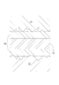
- the sound absorbing material laminated structure according to the present embodiment includes felts 11 and 12 as the sound absorbing material, a sheet-like intermediate inclusion 13 disposed between the felts 11 and 12, and a felt.
- the cover bodies 14 and 15 made of a flexible material that covers the surfaces of 11 and 12 are laminated and integrated.
- the felts 11 and 12 are well-known flexible porous bodies in which natural fibers and synthetic fibers are aggregated and combined and integrated into a sheet shape, and elastic that can be compressed and restored slightly in the thickness direction. It also has.
- the thicknesses of the felts 11 and 12 are set to, for example, about 10 mm. Further, the felts 11 and 12 do not need to have a uniform structure in the entire thickness direction, and the frequency of sound that can be absorbed by one layer of felt by changing properties such as density at each position in the thickness direction. A composite structure with a wide band may be used.
- the felts 11 and 12 constituting the sound absorbing material have a mechanism capable of absorbing energy of external force that causes deformation, that is, sound, by causing friction between the internal fiber materials in the process of deformation.
- the intermediate inclusion 13 is formed as a very thin sheet-like body having flexibility.
- the thickness of the intermediate inclusion 13 is set to a value that is negligibly small with respect to the thickness of the felts 11 and 12 that are sound absorbing materials, for example, about 0.1 mm.
- the thickness corresponding to the use situation can be selected as appropriate.
- the intermediate inclusion 13 has a large number of through-holes having a large opening size with respect to its thickness, for example, circular holes 13a having a diameter of 25 mm in the case of a thickness of 0.1 mm, arranged at predetermined intervals in the front, rear, left and right. It is a configuration to be provided.
- the intermediate inclusion 13 and the felts 11 and 12 are laminated and bonded and integrated using an adhesive.
- the felts 11 and 12 may have a surface roughness or unevenness larger than the thickness of the intermediate inclusion 13, and also the elasticity of the felt itself ( Due to the (bulkyness), it is possible to directly contact the ones sandwiching the hole 13a (see FIG. 1). For this reason, in the hole 13a position, the directly opposing felts 11 and 12 are bonded together with an adhesive and integrated.
- the cover bodies 14 and 15 are thin sheets made of cloth or elastic material and have flexibility to cover and protect the surfaces of the felts 11 and 12, and to allow sound to pass or partially reflect. It has a function.
- the pressure-sensitive adhesive 16 is stored and stored as a liquid pressure-sensitive adhesive composition that does not exhibit adhesiveness and is easy to handle, and after application to an object to be bonded, a predetermined time elapses and the liquid content is lost. In other words, it has the property of exhibiting stable adhesiveness and shifting to a state where it has become an original adhesive.
- an acrylic pressure-sensitive adhesive is finally obtained as a pressure-sensitive adhesive
- an aqueous emulsion of an acrylate ester copolymer is used as the pressure-sensitive adhesive composition.
- the pressure-sensitive adhesive composition has the property that it does not penetrate into the sound absorbing material and does not form a film on the surface of the sound absorbing material when applied to the sound absorbing material such as felt. It exists in a part, and it interposes between a sound-absorbing material and an intermediate inclusion, maintaining this state after bonding.
- the felt When the felts 11 and 12 and the intermediate inclusion 13 are laminated and integrated, the felt is in a state in which a liquid pressure-sensitive adhesive composition is applied to one or both of the felt and the intermediate inclusion.
- the adhesive composition When the intermediate inclusion 13 is placed between the intermediate inclusions 11 and 12 and laminated, the adhesive composition exhibits adhesiveness between the felts 11 and 12 and the intermediate inclusion 13 after a predetermined time has elapsed.
- the felts 11 and 12 and the intermediate inclusion 13 are integrated with each other through the adhesive. It should be noted that the pressure-sensitive adhesive having a strong adhesive force that is finally expressed is used, and when the felts 11 and 12 and the intermediate inclusion 13 are laminated, the pressure-sensitive adhesive composition is applied only to the intermediate inclusion 13 side. It is preferable to do this.
- the pressure-sensitive adhesive 16 is provided between the felts 11 and 12 and the intermediate inclusions 13 to express the adhesiveness, and is applied from the outside to release the bonds between the fiber materials constituting the felts 11 and 12. It is assumed that the adhesive has such an adhesive force that it can maintain the adhesive integrated state with the felts 11 and 12 with respect to the minimum peeling force that can partly peel the part.
- the felt itself cannot withstand the peeling force applied to the felts 11 and 12, and the other part peels off from the part attached to the intermediate inclusion 13.
- the adhesive 16 can reliably maintain the state in which the felts 11 and 12 and the intermediate inclusion 13 are integrated with each other until the laminated body cannot maintain its form, and is necessary and sufficient as the whole laminated body. High strength can be secured.
- the laminated body 10 finally obtained by having a laminated structure such as the felts 11 and 12 and the intermediate inclusions 13 suppresses unnecessary reflection of sound around a person who listens to a sound source such as a musical instrument.
- a sound source such as a musical instrument.
- a liquid pressure-sensitive adhesive composition that does not express adhesiveness is applied to one surface of the intermediate inclusion 13 over the entire surface. After quickly applying to the entire surface, before the liquid content of the applied adhesive composition on the intermediate inclusion 13 partially volatilizes and the viscosity becomes high, the intermediate inclusion 13 to which this adhesive composition is applied, The felt 11 which is a sound absorbing material is laminated and bonded together.
- the adhesive composition is also applied to the other surface of the intermediate inclusion 13 in the same manner as described above.
- the pressure-sensitive adhesive composition is also attached to the surface portion of the felt 11 that overlaps the hole 13a position of the intermediate inclusion 13.
- the felt 12 After applying the pressure-sensitive adhesive composition, the felt 12 is laminated and bonded to the intermediate inclusion 13. Further, the pressure-sensitive adhesive composition is applied to the cover bodies 14 and 15, and the cover bodies 14 and 15 are attached to the surfaces of the felts 11 and 12. After that, if the liquid component of the pressure-sensitive adhesive composition is volatilized and shifts to the original state of the pressure-sensitive adhesive, each member sandwiching the pressure-sensitive adhesive 16 becomes an integrated state that is not easily separated by pressure-sensitive adhesive, The laminate 10 is completed. At each hole 13a position of the intermediate inclusion 13 in this laminated state, the felts 11 and 12 arranged so as to sandwich the intermediate inclusion 13 are stuck to each other with an adhesive.
- the pressure-sensitive adhesive composition is applied to the other surface of the intermediate inclusion 13 in the same manner, and the felt 12 is overlapped and bonded to transfer the pressure-sensitive adhesive composition to the pressure-sensitive adhesive.
- the cover bodies 14 and 15 are attached to the surfaces of the felts 11 and 12, and the pressure-sensitive adhesive composition is transferred to the pressure-sensitive adhesive, the laminate 10 As it is completed.
- the laminate 10 is installed on the floor, ceiling, or wall interior side where it is desired to suppress unnecessary reflection of sound.
- Felts 11 and 12 that are weak in strength are laminated and integrated with other members, and the surfaces are covered with cover bodies 14 and 15, so that there is no problem in handling during installation and the installation can be easily performed.
- the laminated body 10 When sound reaches the laminated body 10, first, sound in a part of the frequency band is reflected on the surface of the cover body 14, and the remaining sound passes through the cover body 14. The sound that has passed through the cover body 14 reaches the felt 11 inside thereof, and a part of the sound is absorbed by the felt 11. Further, in the pressure-sensitive adhesive portion where the felt 11 and the intermediate inclusion 13 are bonded together, the pressure-sensitive adhesive 16 is not cured, and the pressure-sensitive adhesive 16 allows deformation of both and does not excessively constrain adjacent portions. Further, since the sound is not reflected by reflecting the sound, the sound passing through the felt 11 reaches the intermediate inclusion 13 through the adhesive part.
- the sound is partially reflected as designed according to the nature of the intermediate inclusion 13, while the remaining components that are not reflected by the sound pass through the intermediate inclusion 13 on the opposite surface. Reach.
- the adhesive is not cured on the other surface of the intermediate inclusion 13, and in addition to allowing deformation by the sound of the intermediate inclusion 13 and the felt 12, the sound is not reflected. It will reach the 12th side.
- the hole 13a part in the intermediate inclusion 13 by integrating the felts 11 and 12 without curing the adhesive 16 that directly bonds the felts 11 and 12 in the hole 13a part, The sound is not reflected at the boundary and can be passed through, and the sound absorption by the felts 11 and 12 facing the hole 13a functions without any problem. The passage and reflection of the sound by the intermediate inclusion 13 by the hole 13a. The function of adjusting the state will be sufficiently exhibited.
- the sound is further absorbed and attenuated when passing through the felt 12, reaches the cover body 15 opposite to the side on which the sound is incident, part passes through and reaches the outside, and the rest reflects and returns to the felt 12. .
- the sound that reaches the outside is reflected by the ceiling or wall located behind the laminated body 10, and part of the reflected sound reaches the surface of the cover body 15 of the laminated body again, and part of the reflected sound passes through the cover body 15.
- the felt 12 is reached.
- Each reflected sound from the intermediate inclusion 13 and the cover body 15 and the reflected sound that once exits the laminated body 10 and returns to the laminated body 10 from the outside are further absorbed and attenuated while passing through the reverse path. Will be.
- a part of the sound finally returning to the front side of the laminated body passes through the cover member 14 and is directed to a person in the room space, that is, a person who listens to the sound from the sound source as a very slight reflected sound.
- the sound field feeling based on a large level of reflected sound including noise from the ceiling and walls close to people, can be obtained, and the ceiling and walls are sufficiently separated from people, and noise is almost completely reflected in the reflected sounds. It can be given to people in place of a sound field feeling that is much closer to a larger space than general rooms such as halls that are not included, and it can greatly improve the environment for listening to human sounds by generating an appropriate sound field feeling It will be planned.
- the sound-absorbing material laminated structure according to the present embodiment is bonded using the adhesive 16 that expresses adhesive performance later when the felts 11 and 12 and the intermediate inclusions 13 and the like are laminated.
- the felts 11 and 12 and the intermediate inclusions 13 and the like are integrated without curing the adhesive 16 interposed therebetween.
- the adhesive 16 maintains the adhesive state on the surface of the felts 11 and 12, and this uncured adhesive 16 does not serve as a sound reflection part, and the layers of the laminated structure integrated with the adhesive 16 are not excessively constrained, and the integrity in the handling state is reliably maintained while the layers between the layers based on the vibration of the sound are maintained.
- the effect of absorbing sound with the felts 11 and 12 facing the boundary portion is allowed.
- the laminated body 10 as a whole can appropriately absorb and reflect sound to obtain appropriate characteristics, and the sound field can be adjusted reliably.
- the intermediate inclusion 13 is configured to have a large number of through-holes having a large opening dimension with respect to its thickness.
- the intermediate inclusion 17 can be configured not to have a hole, and desired sound reflection characteristics can be obtained as a whole laminate. The sound field can be adjusted according to the application.
- the intermediate inclusion 13 is configured to have a flexible sheet shape, but the present invention is not limited to this, and the intermediate inclusion is formed in a thin plate shape that is not flexible. It can also be configured, improving the difficulty of deformation in the state of the laminated body, handle the laminated body as a panel that does not easily deform, can be leaned against the wall, etc. when installing the panel, and leaned In some applications, the handling can be further facilitated.
- the sound-absorbing material laminated structure when the musical instrument played by the performer as the target person is a sound source, the reflected sound in the indoor space of the sound emitted from the musical instrument reaches the performer.
- the sound absorber is changed to adjust the player's sense of sound field so that the player can practice the performance while having a sound field feeling similar to that of the demonstration venue.
- the object For a sound source that is not a musical instrument or a singer himself at a position away from a target person who is not a singer or a singer, the object is placed near the target person, and the state in which the reflected sound in the indoor space reaches the target person is changed.
- the sound absorbing material laminated structure of the present invention While confirming that the sound absorbing material laminated structure of the present invention has sufficient strength to withstand the use of the laminated integration using an adhesive, the sound absorbing material laminated structure of the present invention is actually sounded. A description will be given of the results of measurement and evaluation performed on the reflected sound generated in the laminated body by receiving the sound emitted from the sound source and used for the field adjustment.
- the felt as a sound absorbing material is bonded to another member using an adhesive, and when the peeling force is applied to the felt, the change in the integrated state of adhesion between the felt and the other member is observed. It evaluated about the adhesive force of the adhesive which concerns on a maintenance.
- pressure-sensitive adhesives There are two types of pressure-sensitive adhesives, one having strong adhesive strength and one having weak adhesiveness, both of which are volatile from the state of a liquid pressure-sensitive adhesive composition that does not exhibit adhesiveness. It is an acrylic pressure-sensitive adhesive that has the property of exhibiting tackiness and changing to the original pressure-sensitive adhesive state.
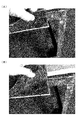
- a liquid pressure-sensitive adhesive composition is applied to the surface of the plate and applied. After the adhesive composition is changed to a state in which a part of the adhesive composition exhibits adhesiveness, the felt is laminated on the plate. After that, sufficient time has passed, and the adhesive composition has fully developed adhesiveness and transferred to the original adhesive, and it can be considered that this adhesive adheres to both the felt and the plate and integrates them. After reaching the state, apply a peeling force to peel off the felt from the plate by hand.
- Fig. 4 and Fig. 5 show the situation where a peeling force is applied to a felt laminated with a strong adhesive
- Fig. 5 shows the situation where a peeling force is applied to a felt laminated with a weak adhesive.
- the laminate having the sound-absorbing material laminate structure of the present invention is appropriately disposed in the test room space, and when sound is emitted from the sound source, the frequency of the reflected sound from the laminate is determined for each frequency. The sound pressure level was measured. The laminate was measured in the same manner for each of the case where the adhesive having a strong adhesive force and the adhesive having a weak adhesive force were used.
- the laminated body is arranged with a felt as a sound absorbing material sandwiching an extremely thin sheet-like intermediate inclusion, and further, as a cover body covering the surface of the felt, one is a cloth and the other is an EVA resin sheet.
- a felt as a sound absorbing material sandwiching an extremely thin sheet-like intermediate inclusion
- a cover body covering the surface of the felt one is a cloth and the other is an EVA resin sheet.
- the liquid adhesive composition is applied to the intermediate inclusions and the cover bodies by bonding the felt, which is a sound-absorbing material, and other members at the time of lamination. After being applied only, they are laminated with a sound absorbing material to form a laminated state.
- the adhesive having a weak adhesive force the liquid adhesive composition can be applied not only to the intermediate inclusions and the side of each cover body by bonding the felt and the other member at the time of lamination. After being applied also to the felt surface, these are laminated so that the adhesive force of the adhesive interposed between the layers is more reliably generated.
- the sound source is placed in the approximate center of the space, the laminate is placed along the wall surface, and the microphone is placed near another wall surface where the laminate is not placed.
- a sine wave fundamental tone of 80 Hz, 250 Hz, 400 Hz, and 2000 Hz was output, and the reflected sound was measured.
- the frequency component was obtained from the time waveform of the sound by fast Fourier transform.
- Example 1 the graph of the sound pressure level for each frequency for each fundamental tone obtained by measurement in the case where the laminate using the adhesive having strong adhesive force is disposed in the indoor space is shown in FIGS. Show. Further, as Example 2, a graph of the sound pressure level for each frequency for each fundamental tone obtained by measurement in the case where a laminate using the adhesive having a weak adhesive force is arranged in an indoor space is shown in FIG. 11 shows. In each graph, the horizontal axis represents frequency and the vertical axis represents sound level. However, since the indoor space that is the measurement environment does not have an anechoic and completely sound-insulating structure, background noise exists.
- the sound pressure level of the fundamental frequency in the reflected sound is 24.5 dB at 80 Hz, 10.7 dB at 250 Hz, 19.9 dB at 400 Hz, and 12.3 dB at 2000 Hz.
- it is 24.5 dB at 80 Hz, 16.9 dB at 250 Hz, 19.9 dB at 400 Hz, and 19.6 dB at 2000 Hz.
- the higher-order overtone components that are the basis of the natural timbre appear without being lost, and the level of the higher frequency decreases as compared with the case of the second embodiment. It is in a state with natural and unreasonable attenuation (80 Hz, 250 Hz, 400 Hz) or a state in which a higher harmonic component appears appropriately (250 Hz, 2000 Hz) while the level of the reflected sound of the fundamental tone is greatly reduced. . That is, the laminated body of Example 1 has been adjusted so that unnecessary reflections are suppressed and appropriate sound absorption is performed so that a natural tone color can be obtained in the indoor space. I understand.
- Example 1 does not apply the pressure-sensitive adhesive composition to the sound absorbing material side, so there are fewer constraints at the boundary between the sound absorbing material and other members, and the sound absorbing performance is more efficient and It is thought that it does not cause unnecessary reflections to cancel each other over harmonic components, so that higher harmonic components remain, and the reflected sound level of the fundamental tone is suppressed. It is done.
- the obtained laminated body can suppress the influence of unnecessary reflection of sound, and can appropriately adjust the sound field, accompanied by a natural tone. It is clear that people can be given an excellent sound field feeling.
Abstract
Description
前記各図において本実施形態に係る吸音材積層構造は、前記吸音材としてのフェルト11、12と、フェルト11、12の間に介在させて配設されるシート状の中間介在物13と、フェルト11、12の表面を覆う可撓性材料製のカバー体14、15とを積層一体化したものである。
この吸音材をなすフェルト11、12は、変形の過程で内部の繊維素材相互に摩擦等が生じることで、変形をもたらす外力のエネルギー、すなわち音を吸収できる仕組みである。
11、12 フェルト
13、17 中間介在物
13a 孔
14、15 カバー体
16 粘着剤
Claims (4)
- 一又は複数の吸音材と一又は複数の中間介在物及び/又は表面のカバー体とを積層一体化した吸音材の積層構造において、
前記中間介在物が、可撓性を有するシート状、又は柔軟でない薄板状とされ、
多孔質の略板状体とされる複数の吸音材と、前記中間介在物とが、前記吸音材と中間介在物のいずれか一方又は両方に、液状で粘着性を発現していない粘着剤組成物を塗布した上で、吸音材間に中間介在物を位置させて積層され、
塗布された前記粘着剤組成物は、粘着性を発現して本来の粘着剤となった状態に変化し、当該粘着剤が、前記吸音材と中間介在物のそれぞれに粘着して、吸音材と中間介在物とを一体化することを
特徴とする吸音材積層構造。 - 前記請求項1に記載の吸音材積層構造において、
前記中間介在物が、前記吸音材に比べて極めて薄く形成され、且つ、中間介在物の厚さに比べて開口寸法が大きく、中間介在物を挟む吸音材同士の直接接触をもたらす貫通孔を、所定間隔で多数穿設されてなり、
積層状態で前記中間介在物の孔位置に重なる吸音材表面部にも、粘着剤組成物が配設され、
積層状態における中間介在物の各孔位置で、吸音材同士が粘着剤により貼着一体化されることを
特徴とする吸音材積層構造。 - 前記請求項1又は2に記載の吸音材積層構造において、
前記吸音材が、フェルトであり、
前記粘着剤が、外部から加えられる、吸音材をなす繊維素材同士の結合を解いて吸音材の一部を剥離させることのできる最小の引き剥がし力に対し、吸音材との粘着一体化状態を維持可能な大きさとなる粘着力を有することを
特徴とする吸音材積層構造。 - 前記請求項1ないし3のいずれかに記載の吸音材積層構造において、
前記吸音材と中間介在物との積層に際し、中間介在物側に液状の粘着剤組成物を塗布して、粘着剤組成物を吸音材に浸透させず、
粘着性を発現した粘着剤を、吸音材における多孔質構造の最外方部分にのみ存在させる状態で、積層した吸音材と中間介在物との間に介在させることを
特徴とする吸音材積層構造。
Priority Applications (8)
| Application Number | Priority Date | Filing Date | Title |
|---|---|---|---|
| EP11862906.2A EP2696341A4 (en) | 2011-04-08 | 2011-04-08 | LAMINATE STRUCTURE OF SOUNDS ABSORBING MATERIAL |
| BR112013025907A BR112013025907A2 (pt) | 2011-04-08 | 2011-04-08 | estrutura laminada de absorção acústica |
| KR1020137029758A KR20140027984A (ko) | 2011-04-08 | 2011-04-08 | 흡음재 적층 구조 |
| PCT/JP2011/058944 WO2012137353A1 (ja) | 2011-04-08 | 2011-04-08 | 吸音材積層構造 |
| CN201180071467.XA CN103597539B (zh) | 2011-04-08 | 2011-04-08 | 吸音材料层叠结构 |
| CA2835178A CA2835178A1 (en) | 2011-04-08 | 2011-04-08 | Sound absorbing member lamination structure |
| JP2013508713A JP5932774B2 (ja) | 2011-04-08 | 2011-04-08 | 吸音材積層構造 |
| US14/041,586 US9027705B2 (en) | 2011-04-08 | 2013-09-30 | Sound-absorbing member lamination structure |
Applications Claiming Priority (1)
| Application Number | Priority Date | Filing Date | Title |
|---|---|---|---|
| PCT/JP2011/058944 WO2012137353A1 (ja) | 2011-04-08 | 2011-04-08 | 吸音材積層構造 |
Related Child Applications (1)
| Application Number | Title | Priority Date | Filing Date |
|---|---|---|---|
| US14/041,586 Continuation US9027705B2 (en) | 2011-04-08 | 2013-09-30 | Sound-absorbing member lamination structure |
Publications (1)
| Publication Number | Publication Date |
|---|---|
| WO2012137353A1 true WO2012137353A1 (ja) | 2012-10-11 |
Family
ID=46968786
Family Applications (1)
| Application Number | Title | Priority Date | Filing Date |
|---|---|---|---|
| PCT/JP2011/058944 WO2012137353A1 (ja) | 2011-04-08 | 2011-04-08 | 吸音材積層構造 |
Country Status (8)
| Country | Link |
|---|---|
| US (1) | US9027705B2 (ja) |
| EP (1) | EP2696341A4 (ja) |
| JP (1) | JP5932774B2 (ja) |
| KR (1) | KR20140027984A (ja) |
| CN (1) | CN103597539B (ja) |
| BR (1) | BR112013025907A2 (ja) |
| CA (1) | CA2835178A1 (ja) |
| WO (1) | WO2012137353A1 (ja) |
Cited By (3)
| Publication number | Priority date | Publication date | Assignee | Title |
|---|---|---|---|---|
| US8919048B2 (en) | 2012-07-31 | 2014-12-30 | Interman Corporation | Mobile terminal booth |
| WO2015012379A1 (ja) * | 2013-07-25 | 2015-01-29 | インターマン株式会社 | 携帯端末用ブース |
| US20150034413A1 (en) * | 2013-08-02 | 2015-02-05 | Interman Corporation | Sound control apparatus |
Families Citing this family (5)
| Publication number | Priority date | Publication date | Assignee | Title |
|---|---|---|---|---|
| CN105023566B (zh) * | 2014-04-28 | 2019-08-30 | 正升环境科技股份有限公司 | 复合吸隔声板及其制作方法 |
| JP6043407B2 (ja) * | 2015-02-27 | 2016-12-14 | 富士フイルム株式会社 | 防音構造、及び防音構造の製造方法 |
| US9469985B1 (en) * | 2015-05-11 | 2016-10-18 | Hexcel Corporation | Acoustic structures with multiple degrees of freedom |
| CN105161089B (zh) * | 2015-06-17 | 2019-10-15 | 成都斯铂润音响设备有限公司 | 一种吸声装置 |
| EA037908B1 (ru) * | 2018-11-12 | 2021-06-04 | Владимир Вячеславович СЕМЬЯНОВ | Акустический барьер |
Citations (10)
| Publication number | Priority date | Publication date | Assignee | Title |
|---|---|---|---|---|
| JPH05187074A (ja) * | 1992-01-13 | 1993-07-27 | Hayakawa Rubber Co Ltd | 吸音部材 |
| JPH10254452A (ja) | 1997-03-12 | 1998-09-25 | Kuraray Co Ltd | 吸音材 |
| JPH113082A (ja) | 1997-06-12 | 1999-01-06 | Kobe Steel Ltd | 金属製吸音材 |
| JP2001207366A (ja) | 2000-01-28 | 2001-08-03 | Teijin Ltd | 吸音用繊維構造体 |
| JP2002082671A (ja) * | 2000-09-06 | 2002-03-22 | Nichias Corp | 吸音構造体 |
| JP2002169566A (ja) * | 2000-12-04 | 2002-06-14 | Nippon Tokushu Toryo Co Ltd | 粘着加工防音材及び粘着加工方法 |
| JP2006030905A (ja) | 2004-07-21 | 2006-02-02 | Nippon Ester Co Ltd | 吸音材 |
| JP2006030965A (ja) | 2004-07-19 | 2006-02-02 | Samsung Electronics Co Ltd | 位相遅延素子とその製造方法、これを有する基板とその製造方法、これを用いた光供給方法、及び液晶表示装置 |
| JP2009287143A (ja) | 2008-05-29 | 2009-12-10 | Kenatekkusu:Kk | 吸音材及びその製造方法 |
| WO2011013427A1 (ja) * | 2009-07-31 | 2011-02-03 | 名古屋油化株式会社 | 接着性吸音シート、吸音表皮材、吸音材料および吸音材料成形物 |
Family Cites Families (16)
| Publication number | Priority date | Publication date | Assignee | Title |
|---|---|---|---|---|
| JPS60102310U (ja) * | 1983-12-16 | 1985-07-12 | 株式会社ブリヂストン | 制振遮音板 |
| US4594278A (en) * | 1984-01-20 | 1986-06-10 | Nixon Michael T | Acoustical panels |
| JPH108591A (ja) * | 1996-06-21 | 1998-01-13 | Bridgestone Corp | 吸音部材 |
| JP2000112482A (ja) * | 1998-10-09 | 2000-04-21 | Tamagawa Seni Kogyosho:Kk | 吸音シートおよび吸音シート積層体 |
| US8413262B2 (en) * | 2004-05-28 | 2013-04-09 | Matscitechno Licensing Company | Sound dissipating material |
| JP4255856B2 (ja) * | 2004-02-09 | 2009-04-15 | 三乗工業株式会社 | 吸音材とその製造方法 |
| WO2008113004A1 (en) * | 2007-03-14 | 2008-09-18 | Futuris Automotive Interiors (Us), Inc. | Low mass acoustically enhanced floor carpet system |
| CA2681528C (en) * | 2007-03-21 | 2018-10-23 | Ashtech Industries, Llc | Utility materials incorporating a microparticle matrix |
| US9388568B2 (en) * | 2007-04-06 | 2016-07-12 | Pacific Coast Building Products, Inc. | Acoustical sound proofing material with improved fracture characteristics and methods for manufacturing same |
| CA2709794C (en) * | 2008-02-14 | 2014-11-18 | Nagoya Oilchemical Co., Ltd. | Sound absorbing skin material and sound absorbing material utilizing the same |
| US20090250292A1 (en) * | 2008-04-08 | 2009-10-08 | Howa Textile Industry Co., Ltd. | Automotive sound-absorbing material |
| EP2297412B1 (en) * | 2008-05-23 | 2018-06-13 | Zephyros Inc. | Sound absorption material and method of manufacturing sound absorption material |
| WO2010038486A1 (ja) * | 2008-10-02 | 2010-04-08 | 名古屋油化株式会社 | 吸音材料、複層吸音材料、成形複層吸音材料、吸音性内装材料及び吸音性床敷材料 |
| CN102271905B (zh) * | 2009-01-06 | 2015-02-18 | 塞特克技术公司 | 具有改进的声学和震动阻尼性能的结构复合材料 |
| US8496088B2 (en) * | 2011-11-09 | 2013-07-30 | Milliken & Company | Acoustic composite |
| KR101846574B1 (ko) * | 2012-11-26 | 2018-04-06 | 현대자동차주식회사 | 자동차용 복합흡음재 및 그 제조방법 |
-
2011
- 2011-04-08 CA CA2835178A patent/CA2835178A1/en not_active Abandoned
- 2011-04-08 BR BR112013025907A patent/BR112013025907A2/pt not_active IP Right Cessation
- 2011-04-08 EP EP11862906.2A patent/EP2696341A4/en not_active Withdrawn
- 2011-04-08 CN CN201180071467.XA patent/CN103597539B/zh not_active Expired - Fee Related
- 2011-04-08 KR KR1020137029758A patent/KR20140027984A/ko not_active Application Discontinuation
- 2011-04-08 JP JP2013508713A patent/JP5932774B2/ja active Active
- 2011-04-08 WO PCT/JP2011/058944 patent/WO2012137353A1/ja active Application Filing
-
2013
- 2013-09-30 US US14/041,586 patent/US9027705B2/en not_active Expired - Fee Related
Patent Citations (10)
| Publication number | Priority date | Publication date | Assignee | Title |
|---|---|---|---|---|
| JPH05187074A (ja) * | 1992-01-13 | 1993-07-27 | Hayakawa Rubber Co Ltd | 吸音部材 |
| JPH10254452A (ja) | 1997-03-12 | 1998-09-25 | Kuraray Co Ltd | 吸音材 |
| JPH113082A (ja) | 1997-06-12 | 1999-01-06 | Kobe Steel Ltd | 金属製吸音材 |
| JP2001207366A (ja) | 2000-01-28 | 2001-08-03 | Teijin Ltd | 吸音用繊維構造体 |
| JP2002082671A (ja) * | 2000-09-06 | 2002-03-22 | Nichias Corp | 吸音構造体 |
| JP2002169566A (ja) * | 2000-12-04 | 2002-06-14 | Nippon Tokushu Toryo Co Ltd | 粘着加工防音材及び粘着加工方法 |
| JP2006030965A (ja) | 2004-07-19 | 2006-02-02 | Samsung Electronics Co Ltd | 位相遅延素子とその製造方法、これを有する基板とその製造方法、これを用いた光供給方法、及び液晶表示装置 |
| JP2006030905A (ja) | 2004-07-21 | 2006-02-02 | Nippon Ester Co Ltd | 吸音材 |
| JP2009287143A (ja) | 2008-05-29 | 2009-12-10 | Kenatekkusu:Kk | 吸音材及びその製造方法 |
| WO2011013427A1 (ja) * | 2009-07-31 | 2011-02-03 | 名古屋油化株式会社 | 接着性吸音シート、吸音表皮材、吸音材料および吸音材料成形物 |
Non-Patent Citations (1)
| Title |
|---|
| See also references of EP2696341A4 * |
Cited By (9)
| Publication number | Priority date | Publication date | Assignee | Title |
|---|---|---|---|---|
| US8919048B2 (en) | 2012-07-31 | 2014-12-30 | Interman Corporation | Mobile terminal booth |
| US8978314B2 (en) | 2012-07-31 | 2015-03-17 | Interman Corporation | Mobile terminal booth |
| WO2015012379A1 (ja) * | 2013-07-25 | 2015-01-29 | インターマン株式会社 | 携帯端末用ブース |
| CN105492709A (zh) * | 2013-07-25 | 2016-04-13 | 因特曼股份有限公司 | 移动终端用隔间 |
| EP3029221A1 (en) * | 2013-07-25 | 2016-06-08 | Interman Corporation | Booth for portable terminal |
| US9523191B2 (en) | 2013-07-25 | 2016-12-20 | Interman Corporation | Mobile terminal booth |
| EP3029221A4 (en) * | 2013-07-25 | 2017-03-29 | Interman Corporation | Booth for portable terminal |
| US20150034413A1 (en) * | 2013-08-02 | 2015-02-05 | Interman Corporation | Sound control apparatus |
| JP2015031844A (ja) * | 2013-08-02 | 2015-02-16 | インターマン株式会社 | 音響調整装置 |
Also Published As
| Publication number | Publication date |
|---|---|
| KR20140027984A (ko) | 2014-03-07 |
| EP2696341A4 (en) | 2014-12-17 |
| US9027705B2 (en) | 2015-05-12 |
| JP5932774B2 (ja) | 2016-06-08 |
| US20140097038A1 (en) | 2014-04-10 |
| CN103597539A (zh) | 2014-02-19 |
| EP2696341A1 (en) | 2014-02-12 |
| CN103597539B (zh) | 2015-11-25 |
| BR112013025907A2 (pt) | 2016-12-20 |
| CA2835178A1 (en) | 2012-10-11 |
| JPWO2012137353A1 (ja) | 2014-07-28 |
Similar Documents
| Publication | Publication Date | Title |
|---|---|---|
| JP5932774B2 (ja) | 吸音材積層構造 | |
| EP1979555B1 (en) | Apparatus for absorbing acoustical energy and use thereof | |
| ES2945689T3 (es) | Material de insonorización acústica con amortiguación mejorada en frecuencias seleccionadas y métodos para la fabricación del mismo | |
| WO2009129139A3 (en) | Multilayer sound absorbing sheet | |
| JP5531343B2 (ja) | 間仕切りパネル | |
| US7770693B2 (en) | Mat for acoustic apparatus | |
| JP2011521300A5 (ja) | ||
| TW201501549A (zh) | 用以製造聲學振膜之複合體及聲學振膜 | |
| EP2146339A2 (en) | Sound absorbing device | |
| JP2006323204A (ja) | 複層吸音構造体 | |
| JP2001065077A (ja) | 吸音パネル | |
| JP2006332861A (ja) | スピーカ装置、スピーカ付き作業口蓋及びスピーカ付き壁パネル | |
| AU2008288674B2 (en) | An acoustic panel | |
| US11423868B2 (en) | Keyboard device and musical sound emission method | |
| CN212405537U (zh) | 隔音板材 | |
| US7912238B2 (en) | Speaker attenuation system, method and apparatus | |
| JPH07261767A (ja) | 音響調整材 | |
| JP2006115303A (ja) | スピーカボックス | |
| JP2005303712A5 (ja) | ||
| JP3123028U (ja) | 吸音材 | |
| JPH01156797A (ja) | 吸音装置 | |
| EP4216572A3 (en) | Noise-reducing loudspeaker | |
| JPH0671613U (ja) | 吸音板 | |
| JP2020053970A (ja) | 圧電スピーカーの製造方法 | |
| JP2002220889A (ja) | 入隅用吸音具 |
Legal Events
| Date | Code | Title | Description |
|---|---|---|---|
| 121 | Ep: the epo has been informed by wipo that ep was designated in this application |
Ref document number: 11862906 Country of ref document: EP Kind code of ref document: A1 |
|
| ENP | Entry into the national phase |
Ref document number: 2013508713 Country of ref document: JP Kind code of ref document: A |
|
| NENP | Non-entry into the national phase |
Ref country code: DE |
|
| ENP | Entry into the national phase |
Ref document number: 2835178 Country of ref document: CA |
|
| WWE | Wipo information: entry into national phase |
Ref document number: 2011862906 Country of ref document: EP |
|
| ENP | Entry into the national phase |
Ref document number: 20137029758 Country of ref document: KR Kind code of ref document: A |
|
| REG | Reference to national code |
Ref country code: BR Ref legal event code: B01A Ref document number: 112013025907 Country of ref document: BR |
|
| ENP | Entry into the national phase |
Ref document number: 112013025907 Country of ref document: BR Kind code of ref document: A2 Effective date: 20131007 |