WO2012133897A1 - Appareil de dégazage sous vide, appareil pour la production de verrerie et procédé pour la production de verrerie - Google Patents
Appareil de dégazage sous vide, appareil pour la production de verrerie et procédé pour la production de verrerie Download PDFInfo
- Publication number
- WO2012133897A1 WO2012133897A1 PCT/JP2012/058987 JP2012058987W WO2012133897A1 WO 2012133897 A1 WO2012133897 A1 WO 2012133897A1 JP 2012058987 W JP2012058987 W JP 2012058987W WO 2012133897 A1 WO2012133897 A1 WO 2012133897A1
- Authority
- WO
- WIPO (PCT)
- Prior art keywords
- pipe
- molten glass
- brick
- vacuum
- wall
- Prior art date
Links
Images


Classifications
-
- C—CHEMISTRY; METALLURGY
- C03—GLASS; MINERAL OR SLAG WOOL
- C03B—MANUFACTURE, SHAPING, OR SUPPLEMENTARY PROCESSES
- C03B5/00—Melting in furnaces; Furnaces so far as specially adapted for glass manufacture
- C03B5/16—Special features of the melting process; Auxiliary means specially adapted for glass-melting furnaces
- C03B5/225—Refining
- C03B5/2252—Refining under reduced pressure, e.g. with vacuum refiners
-
- C—CHEMISTRY; METALLURGY
- C03—GLASS; MINERAL OR SLAG WOOL
- C03B—MANUFACTURE, SHAPING, OR SUPPLEMENTARY PROCESSES
- C03B25/00—Annealing glass products
-
- C—CHEMISTRY; METALLURGY
- C03—GLASS; MINERAL OR SLAG WOOL
- C03B—MANUFACTURE, SHAPING, OR SUPPLEMENTARY PROCESSES
- C03B5/00—Melting in furnaces; Furnaces so far as specially adapted for glass manufacture
- C03B5/16—Special features of the melting process; Auxiliary means specially adapted for glass-melting furnaces
- C03B5/225—Refining
Definitions
- the present invention relates to a vacuum degassing apparatus, a glass product manufacturing apparatus including the vacuum degassing apparatus, and a glass product manufacturing method.
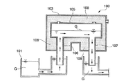
- a vacuum degassing apparatus 100 shown in FIG. 7 is an apparatus used in a process of supplying a molten glass G accommodated in a melting tank 101 under reduced pressure degassing and continuously supplying it to the next processing tank. Is maintained under reduced pressure.
- a vacuum tank 105 is horizontally disposed inside the vacuum housing 103, a rising pipe 106 is vertically attached to the lower part on the inlet side, and a lowering pipe 107 is vertically attached to the lower part on the outlet side. .
- the ascending pipe 106 communicates with the decompression tank 105 and raises the molten glass G before the defoaming treatment from the melting tank 101 and introduces it into the decompression tank 105.
- the downcomer 107 communicates with the decompression tank 105, lowers the molten glass G after the defoaming process from the decompression tank 105, and guides it to the next treatment tank (not shown).
- a heat insulating material 108 such as a heat insulating brick is provided around the decompression tank 105, the ascending pipe 106, and the descending pipe 107.
- the decompression housing 103 is made of metal, such as stainless steel, and is evacuated from the outside by a vacuum pump (not shown) or the like, and the inside of the decompression tank 105 provided therein is in a predetermined decompression state, for example, 1/20 to 1 / By maintaining the pressure at 3 atm, the pressure can be reduced.
- the molten glass G having a temperature of 1200 to 1400 ° C. is decompressed, so that the decompression tank 105, the ascending pipe 106 and the descending pipe 107 are excellent in heat resistance and reactive to the high temperature molten glass G. It is necessary to form with a low material.
- the vacuum tank 105, the rising pipe 106, and the lowering pipe 107 can be formed from a noble metal material having excellent heat resistance such as platinum or a platinum alloy.
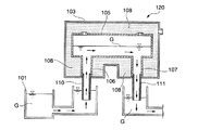
- the decompression tank 105, the riser pipe 106, and the downfall pipe 107 are made of a noble metal material in a large-scale production facility, there is a problem that it is difficult to realize because the equipment cost increases. Therefore, as a device that can solve this problem, the decompression tank 105, the rising pipe 106, and the descending pipe 107 shown in FIG. 8 are formed of refractory bricks.
- a vacuum degassing apparatus 120 having a structure provided with extension pipes 110 and 111 made of a noble metal material has been proposed (see Patent Document 1).
- the rising pipe 106 and the down pipe 107 are kept inside the vacuum housing 103, and the extension pipe 110 made of a noble metal material is extended to the outside of the vacuum housing 103 at the lower end thereof. , 111 are provided.
- the lower ends of these extension pipes 110 and 111 are immersed in the molten glass G.
- the extension pipes 110 and 111 made of a noble metal material are integrated, so that the extension pipe 110 , 111 can be easily realized.
- a structure for supporting the extension pipes 110 and 111 can be provided on the bottom side of the decompression housing 103.
- the extension pipes 110 and 111 are made of a noble metal material and the rising pipe 106 and the downfalling pipe 107 are made of bricks, the amount of expensive noble metal used can be reduced, which is advantageous from the viewpoint of equipment cost.
- the vacuum degassing apparatus 120 having the structure shown in FIG. 8 has the following problems.
- the structure comprised with a firebrick is set as the structure which can be used for a long term according to the durable years of a firebrick.
- the lower ends of the extension pipes 110 and 111 are always immersed in the high-temperature molten glass G. Even if the tubes 110 and 111 are made of a noble metal material having excellent heat resistance, the extension tubes 110 and 111 may be damaged.
- the extension pipes 110 and 111 may be unexpectedly deteriorated, and the extension pipes 110 and 111 may be damaged before reaching the service life. there were.
- the support structure of the extension pipes 110 and 111 described in Patent Document 1 forms a flange at the upper end of the extension pipes 110 and 111, and this flange constitutes the lower end of the ascending pipe 106.
- the horizontal joints or the horizontal joints of the refractory bricks constituting the lower end of the downcomer pipe 107 are sandwiched and supported.
- the ascending pipe 106 and the descending pipe 107 are constructed of bricks, it is preferable to use electroformed bricks having excellent corrosion resistance as the bricks that contact the molten glass G, and heat-resistant bricks are disposed outside the electroformed bricks in the horizontal direction.
- the refractory bricks constituting the lower end of the ascending pipe 106 and the lower end of the descending pipe 107 are disassembled from the joints, and the extension pipes 110 and 111 are not removed. Since the extension pipes 110 and 111 cannot be exchanged, it is necessary to partially disassemble the ascending pipe 106 and the descending pipe 107, resulting in a large construction. For example, after the molten glass G is extracted from the decompression tank 105, the decompression force is released, the ascending pipe 106 and the descending pipe 107 are cooled, and the decompression housing 103 is partially disassembled, and then the bricks of the ascending pipe 106 and the descending pipe 107 are used.
- the present invention has been made in view of the above circumstances, and an object thereof is to provide a vacuum degassing apparatus having a structure in which an extension tube made of a heat-resistant metal immersed in molten glass can be replaced more easily than a conventional structure. Moreover, this invention aims at provision of the manufacturing method of a glass product provided with the method of manufacturing a glass product using the vacuum degassing apparatus provided with the said structure, and the said vacuum degassing apparatus.
- the present invention includes a vacuum housing that is vacuum-sucked, a vacuum tank that is provided in the vacuum housing and into which molten glass is introduced, and a molten glass that is connected to the vacuum tank and provided in the vacuum housing.
- the extension pipe has the proximal end portion
- the outer wall through a fixing means disposed on the outer peripheral portion of the sealing flange at a position inserted into an end brick that constitutes an opening at one end upstream of the pipe or an opening at one end downstream of the outlet pipe
- a vacuum degassing apparatus for molten glass which is removably fixed to the outer surface of the glass.
- the present invention includes a vacuum housing that is vacuum-sucked, a vacuum tank that is provided in the vacuum housing and into which molten glass is introduced, and a molten glass that is connected to the vacuum tank and provided in the vacuum housing.
- An ascending pipe as an upstream inlet pipe of the decompression tank and a descending pipe as a downstream outlet pipe of the decompression tank, and a lower end of the ascending pipe and the lower pipe
- An extension tube made of a heat-resistant metal connected to at least one of them,
- the extension pipe is formed at the lower end of at least one of the ascending pipe and the descending pipe, and extends at the base end at the upper end thereof, the main body part continuous to the base end part, and the outer peripheral side of the main body part.
- a flange for sealing that covers and attaches the insertion hole of the outer wall of the decompression housing from the outer surface side of the outer wall, and the extension pipe has the base end at the lower end opening of the rising pipe or the lowering
- a vacuum depressurization of the molten glass which is removably fixed to the outer surface of the outer wall through fixing means disposed on the outer peripheral portion of the sealing flange at a position inserted into the end brick constituting the lower end opening of the pipe.
- a foaming device is preferred.
- the introduction pipe is configured by assembling an interior brick on the side that comes into contact with the molten glass and an exterior brick that is arranged on the outside in the radial direction of the introduction pipe of the interior brick
- the outlet pipe is configured by assembling an interior brick on the side touching the molten glass and an exterior brick disposed outside the outlet brick in the radial direction of the inner brick
- the outer wall of the decompression housing is upstream of the introduction pipe
- a portion that is in contact with one end on the side or one end on the downstream side of the lead-out pipe, and extends inward in the radial direction of the introduction pipe or the lead-out pipe from the exterior brick, and the end brick is the extension It is preferable to be supported by the outer wall at the formed portion.
- the riser pipe is configured by assembling an interior brick on the side touching the molten glass and an exterior brick disposed outside the riser pipe in the radial direction of the interior brick
- the downcomer is constructed by assembling an interior brick on the side touching the molten glass and an exterior brick disposed outside the downcomer pipe in the radial direction of the interior brick
- the outer wall of the decompression housing is the lower end of the uplift pipe
- a portion that is in contact with a lower end of the downcomer pipe extends to the inside of the riser pipe or the downcomer pipe in a radial direction with respect to the exterior brick, and the end brick extends to the outer wall at the extended portion.
- the end brick has a passage hole through which the molten glass passes, and the passage hole is a large-diameter portion located at the opening on the outer wall side of the passage hole. And a small diameter portion following the large diameter portion, and the extension pipe preferably has an outwardly expanding type extension portion on the base end side of the extension pipe located at the innermost portion of the large diameter portion. .
- a protective member made of a heat-resistant metal that covers the inner peripheral surface may be installed on the inner peripheral surface of the small diameter portion.
- the extended outer surface of the outer wall may be flush with the outer wall, and the end wall of the end brick on the outer wall side may be covered with the sealing flange fixed to the outer wall of the decompression housing.
- the sealing flange may be formed in a dish shape having an outer peripheral edge on the outer peripheral side, and the outer peripheral edge may be attached to the outer wall by a fixing means.
- a preliminary flange is formed on a base end side of the extension pipe from a position where the sealing flange is formed, and an end surface of the end brick on the outer wall side is the preliminary flange. May be covered.
- the introduction pipe and the outlet pipe, or the riser pipe and the downfall pipe may be connected to the decompression tank in the vertical direction.
- the extension pipe may come into contact with either the lower end that is one end on the upstream side of the introduction pipe or the lower end that is one end on the downstream side of the outlet pipe. Good.
- the present invention relates to a glass product comprising a glass melting furnace, the vacuum degassing apparatus, a molding means for molding the molten glass after vacuum degassing, and a slow cooling means for gradually cooling the glass after molding.
- the present invention includes a melting step for melting molten glass, a defoaming step for defoaming molten glass with the above-mentioned vacuum degassing apparatus, a molding step for molding molten glass after the vacuum defoaming treatment, and the molding
- a method for producing a glass product comprising: a slow cooling step of slowly cooling the subsequent glass.
- the extension pipe that has been used while being immersed in the molten glass is removed. be able to. Therefore, it is easy to use a heat-resistant metal extension pipe that has a possibility of shortening the life of the decompression tank, the introduction pipe, and the lead-out pipe made of bricks. It is possible to provide a vacuum degassing apparatus having a highly durable joint structure corresponding to the original life of the bricks constituting the vacuum tank, the introduction pipe and the lead-out pipe.
- the extension pipe can be easily replaced with a new long extension pipe when a large change or adjustment of the degree of vacuum is required due to the difference in the type of glass. Even if it does not modify itself, the vacuum degassing apparatus corresponding to the range of a wider pressure reduction degree can be provided quickly. Furthermore, according to the present invention, it is possible to produce a high-quality glass product with less bubbles over a long period of time using the vacuum degassing apparatus of the present invention having excellent durability.
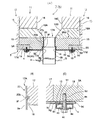
- FIG. 1 is a schematic configuration diagram showing an example of a vacuum degassing apparatus according to a first embodiment of the present invention. It is a figure which shows the principal part of the joining structure of the introductory pipe or derivation
- FIG. 2 (A) is sectional drawing of the whole principal part,
- FIG. Sectional drawing which shows the positional relationship of the passage hole of an edge part and an edge part brick,
- FIG.2 (C) is sectional drawing which shows the attachment structure of the flange outer periphery part for a seal
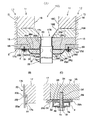
- FIG. 3 (A) is sectional drawing of the whole principal part
- FIG. 3 (B) is an extension pipe
- (C) is sectional drawing which shows the attachment structure of the flange outer periphery part for a seal
- FIG. 3 (C) shows the principal part of the junction structure of the introductory tube or derivation
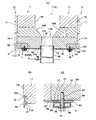
- FIG. 4 (A) is sectional drawing of the whole principal part
- FIG.4 (B) is an extension pipe
- Sectional drawing which shows the positional relationship of the passage hole of the base end part and edge part brick of FIG. 4
- FIG.4 (C) is sectional drawing which shows the attachment structure of the flange peripheral edge part for a seal
- FIG. 5 (A) is sectional drawing of the whole principal part
- FIG.5 (C) is sectional drawing which shows the attachment structure of the flange peripheral edge part for a seal
- a vacuum degassing apparatus 1 shown in FIG. 1 is an apparatus used in a process of degassing high-temperature molten glass G (melt) supplied from a melting tank 2 and continuously supplying it to a molding apparatus 30 in a subsequent process. It is.
- the vacuum degassing apparatus 1 includes a vacuum housing 5 made of an outer wall 5A made of metal, for example, stainless steel, that can keep the inside in a reduced pressure state when used.
- a decompression tank 6 is horizontally disposed inside the decompression housing 5.
- the decompression housing 5 is provided in order to ensure the airtightness of the decompression tank 6, and in the embodiment shown in FIG.
- the material and structure of the decompression housing 5 is not particularly limited as long as it has the airtightness and strength required for the decompression tank 6, but the outer wall 5A made of a heat-resistant metal, particularly stainless steel. It is preferable that it is comprised.
- the decompression housing 5 is vacuumed from the outside by a vacuum pump (not shown) or the like through the exhaust port 5X, and the inside of the decompression tank 6 can be maintained in a predetermined decompressed state, for example, a decompressed state of about 1/20 to 1/3 atm. It is configured as follows.
- An upper end portion of an introduction pipe (that is, a rising pipe) 7 arranged vertically on the bottom lower surface of one end 6A side (left end portion side in FIG. 1, ie, upstream side) of the decompression tank 6 accommodated in the decompression housing 5 Are connected via the inlet 6a, and the upper end of the vertically arranged lead-out pipe (that is, the descending pipe) 8 is formed on the bottom lower surface on the other end 6B side (the right end side in FIG. 1, ie, the downstream side). Are connected via the outlet 6b.
- the ascending pipe 7 passes through an insertion port 5a formed in the outer wall 5A on the bottom side of the decompression housing 5, and the descending pipe 8 passes through an insertion port 5b formed on the outer wall 5A on the bottom side of the decompression housing 5.
- Each is arranged to communicate with the outside.
- the extension pipe 9 which passes through the insertion port 5a of the outer wall 5A and extends downward is connected to the lower end portion of the ascending pipe 7, and the lower end portion of the down pipe 8 passes through the insertion hole 5b of the outer wall 5A and extends downward.
- An extending extension tube 9 is connected.
- the pipe provided on the upstream side of the decompression tank is referred to as an introduction pipe regardless of the direction, but the molten glass is decompressed from the upstream pit of the melting tank.
- the introduction pipe disposed so as to flow vertically or upward toward the tank 6 will be specifically referred to as a riser pipe.
- the pipe provided on the downstream side of the decompression tank is referred to as a lead-out pipe regardless of the direction, but the molten glass is perpendicular to the melting tank toward the downstream pit.
- a lead-out pipe arranged to flow downward or below will be particularly referred to as a downcomer pipe.
- upstream means the upstream side in the flow direction of the molten glass G flowing in the decompression tank 6 of the vacuum degassing apparatus 1, that is, the melting tank side
- downstream means the decompression. It means the downstream side in the flow direction of the molten glass G flowing in the decompression tank 6 of the defoaming device 1, that is, the molding device side.
- a heat insulating material 10 such as a heat insulating brick is disposed around the decompression tank 6, the rise pipe 6, and the down pipe 7, respectively.
- the outside of the pipe 7 and the downcomer pipe 8 is also surrounded by the heat insulating material 10.
- the pressure reducing tank 6, the rising pipe 7, and the downfalling pipe 8 are simply illustrated in FIG. 1, and are respectively provided on the plurality of interior bricks on the side in contact with the molten glass G and outside the interior bricks. It is made into the multilayer structure which consists of the some exterior brick arrange
- the ascending pipe 7 and the descending pipe 8 are arranged in the leg portions 5 ⁇ / b> B and 5 ⁇ / b> C of the outer wall of the decompression housing 5 formed in a substantially portal shape.
- Each of the ascending pipe 7 and the descending pipe 8 shown in FIG. 2A has a multilayer structure in which a plurality of bricks are assembled.
- the inner peripheral portion 11 on the side in direct contact with the molten glass G is configured by assembling a plurality of interior bricks having excellent corrosion resistance such as electroformed bricks, and these outer portions are exterior bricks having high thermal insulation properties such as heat insulating bricks.
- the outer peripheral part 12 is configured by assembling a plurality of parts.
- the decompression tank 6 is also composed of a plurality of interior bricks and exterior bricks as in the case of the ascending pipe 7 and the descending pipe 8, but is simplified and shown as a one-layer structure in FIG.
- the decompression tank 6 and the riser pipe 7 and the downfall pipe 8 are all made of brick, the cost can be greatly reduced compared to the case where they are made of a platinum alloy, and each brick is designed to have a free thickness and size. Since it can do, enlargement of the decompression tank 6 is realizable. Moreover, if the part which touches the molten glass G in the ascending pipe 7 and the descending pipe 8 is made of electroformed brick, it is superior in durability at high temperature than ordinary bricks, and the elution of components can be minimized. The uniformity of the glass G can be maintained. In the present embodiment, the ascending pipe 7 and the descending pipe 8 are configured by assembling these bricks, but the manner of construction of these bricks is not particularly specified.
- a cylindrical tube having a predetermined length can be constructed by filling the joint portion between them with joint material.
- the cylindrical brick previously cast and formed in the cylinder shape etc. may be piled up in a line, and the joint part between them may be filled up with joint material, and the cylindrical pipe
- the electrocast brick is not particularly limited as long as it is a brick that is obtained by electrically melting a refractory raw material and then cast into a predetermined shape, and various types of electrocast bricks of the prior art may be used.
- alumina type electrocast refractories, zirconia type electrocast refractories, AZS (Al 2 O 3 —ZrO 2 —SiO 2 ) type electrocast refractories, etc. are high in corrosion resistance and less foaming from the molten glass substrate.
- marsnite (MB-G), ZB-X950, zirconite (ZB) (all manufactured by AGC Ceramics Co., Ltd.) and the like can be used.
- positioned on the outer side of these interior bricks should just use the well-known brick excellent in heat insulation, and is not specifically limited.
- the lower ends of the ascending pipe 7 and the descending pipe 8 formed into a multilayer structure by the above-described interior brick and exterior brick are joined to the outer wall 5A constituting the decompression housing 5, respectively.
- the cross-sectional structure shown in FIG. Note that the structure of the joint portion between the riser pipe 7 and the outer wall 5A and the structure of the joint portion between the downcomer pipe 8 and the outer wall 5A have the same structure. In FIG. 2, these structures are representative examples.
- the outer peripheral portion 12 of the ascending pipe 7 or the descending pipe 8 is constructed by assembling a plurality of exterior bricks 15, and the inner peripheral portion 11 is constructed by assembling a plurality of interior bricks 16. .
- an end brick 17 is disposed at the lower end (one end) of the ascending pipe 7 and the descending pipe 8, and a passage hole 17 ⁇ / b> A is formed at the center of the end brick 17. It is preferable that the end bricks 17 have a monolithic structure or a small number of bricks in order to reduce joints as much as possible.
- the lower end side of the passage hole 17A also serves as a lower end opening (one end opening) 18 of the ascending pipe 7 or the descending pipe 8, and a base end (upper end) 9a of the extension pipe 9 is formed at the lower end opening 18. Has been inserted.
- a taper-shaped through hole 16B having a tapered shape is formed in the central portion of the first-layer interior brick 16A installed on the end brick 17, and another interior located above the interior is provided.
- the inner diameter of the passage hole is narrower than the passage hole 16 ⁇ / b> C formed in the brick 16. Accordingly, the flow path of the molten glass G is narrowed at the portion of the passage hole 16B, and is formed so as to continue to the passage hole 17A of the end brick 17.
- the end brick 17 is arranged as a kind of the interior brick 16 located inside the exterior brick 15 and is composed of the above-described electroformed brick.
- the lower end opening 18 is a large diameter portion 17a
- the passage hole 17A above the lower end opening 18 is a small diameter portion 17b
- the inner diameter of the large diameter portion 17a is a small diameter portion. It is formed slightly larger than the inner diameter of 17b.
- the large diameter portion 17a is formed to be lower than the small diameter portion 17b.
- the height of the large diameter portion 17a is a fraction of the total height (thickness) of the end brick 17. It is formed to the extent.
- a peripheral step portion 17d is formed on the outer peripheral portion of the bottom surface of the end brick 17, and the outer wall 5A of the decompression housing 5 is extended so as to cover the portion of the peripheral step portion 17d.
- the lowest exterior brick 15 is disposed on the outer wall 5A outside the peripheral step portion 17d. That is, on the lower end portion side of the end brick 15, the insertion hole 5a or the insertion hole 5b formed in the outer wall 5A of the decompression housing 5 is aligned with the peripheral step portion 17d, and the end brick 17 and the exterior brick are aligned. 15 is supported on the outer wall 5 ⁇ / b> A of the decompression housing 5.
- edge part brick 17 of this embodiment is an example, Comprising:
- the edge part brick 17 may be the structure divided
- the extension pipe 9 is extended to the lower side of the rising pipe 7 or the lower side of the lowering pipe 8 below the base end part 9a inserted into the lower end opening 18 of the rising pipe 7 or the lowering pipe 8.
- a cylindrical main body 9b and a disc-shaped sealing flange 9c extending to the outer periphery on the upper end side of the main body 9b, that is, the outer periphery on the lower end side of the base end 9a.
- the sealing flange 9 c extends on the outer periphery of the main body 9 b in a direction perpendicular to the center line of the main body 9 b and is formed so that the outer peripheral edge 9 d reaches the outer wall 5 A of the decompression housing 5. That is, the sealing flange 9c extends so as to cover the insertion hole 5a or the insertion hole 5b formed in the outer wall 5A of the decompression housing 5.
- the outer peripheral edge portion 9d is formed in a thick ring shape, and a plurality of through holes 9e are formed at equal intervals around the outer peripheral edge portion 9d.
- a screw hole 5d is formed in the outer wall 5A of the decompression housing 5 so as to correspond to the formation position of the through hole 9e.
- These screw holes 5d do not need to be formed directly in the outer wall 5A, and may be formed in a ring member or the like that is integrally attached to the outer wall 5A by welding or the like.
- the thick outer peripheral edge portion 9d of the sealing flange 9c may be made of a Ni alloy or other refractory metal material, or may be composed entirely of a noble metal such as platinum.
- the inner peripheral side is close to the high-temperature molten glass G, so that sufficient heat resistance is required for the high-temperature (high temperature of 1200 to 1400 ° C.) molten glass G. Since heat resistance to a lower temperature range is sufficient, it can be formed from a heat-resistant alloy other than a noble metal such as a Ni alloy.
- the sealing flange 9c is screwed to the outer wall 5A by a bolt 19 that passes through a through hole 9e formed in the outer peripheral edge portion 9d of the sealing flange 9c and is screwed into the screw hole 5d of the outer wall 5A. .
- the fixing means for the sealing flange 9c in other words, the fixing means for the extension pipe 9, is constituted by the outer wall 5A having the screw hole 5d and the bolt 19 screwed into the screw hole 5d.
- the fixing means of the extension pipe 9 is not limited to the fixing by the bolt 19, and a structure such as an ISO ferrule union joint may be adopted.
- circumferential grooves 9g and 9h are formed concentrically on the inner surface of the outer peripheral edge 9d, and a heat-resistant seal such as a metal O-ring is formed on the inner circumferential groove 9g.
- a material 13 is inserted, and a sealing material 14 such as a rubber O-ring is inserted into the peripheral groove 9h on the outer peripheral side of the peripheral groove 9g.
- These sealing members 13 and 14 are provided between the outer peripheral edge portion 9d and the outer wall 5A so as to hermetically seal these contact portions when the sealing flange 9c is bolted to the outer wall 5A.
- the cross section of the circumferential groove 9h that accommodates the sealing material 14 can be trapezoidal.
- the reason for making the circumferential groove 9h in this way is to prevent the sealing material 14 from being easily pulled out of the circumferential groove 9h by being restrained inside the trapezoidal circumferential groove 9h when removing the sealing flange 9c.
- the trapezoidal groove is not essential.
- the sealing material 14 is made of a resin such as rubber, the sealing material 14 may be seized on the surface of the outer wall 5A and cannot be removed. If the sealing material 14 is prevented from coming off as the trapezoidal circumferential groove 9h, the sealing material 14 is detached from the outer wall 5A together with the sealing flange 9c when the sealing flange 9c is removed when the extension pipe 9 is replaced. Can be easily removed from the outer wall 5A.
- the cooling jacket 4 made of an annular tube is provided so as to be in contact with the outer peripheral edge 9d of the sealing flange 9c.
- the cooling jacket 4 has a hollow structure, and has a flow path 4a for flowing a refrigerant therein.
- the flow path 4a of the cooling jacket 4 is connected to a refrigerant supply source via a pipe.
- a coolant such as water can be supplied to the flow path 4a from a coolant supply source through a pipe, and the coolant can be circulated by returning the coolant through the pipe, and the sealing materials 13 and 14 and the surrounding portions can be cooled. it can.
- a bolt insertion portion 4c is formed in a portion of the cooling jacket 4 through which the bolt 19 passes so as to be surrounded by the partition wall 4b so as not to disturb the flow path 4a.
- An outwardly expanded (ie, trumpet) extended portion 9 f is formed on the upper end side of the base end portion 9 a of the extension pipe 9, and this extended portion 9 f is the innermost portion of the lower end opening 18 of the end brick 17. In other words, it is arranged at the innermost part of the large diameter part 17a.
- a cylindrical protective member 20 that covers substantially the entire inner peripheral surface of the small-diameter portion 17b is inserted inside the small-diameter portion 17b of the end brick 17.
- This protective member 20 is made of a heat-resistant noble metal material such as platinum or a platinum alloy, and an upper flange 20a is formed at its upper end so as to extend to the opening peripheral edge of the passage hole 17A.
- the lower flange 20b of the protective member 20 is disposed at the innermost part of the large-diameter portion 17a of the end brick 17, and the extension portion 9f on the upper end side of the extension pipe 9 is adjacent to the lower portion of the lower flange 20b. Is arranged.
- the outer diameter of the lower flange 20 b of the protection member 20 and the outer diameter of the extended portion 9 f of the extension pipe 9 are formed slightly smaller than the inner diameter of the lower end opening 18 of the end brick 17. Further, the outer peripheral edge of the lower flange portion 20b formed on the protection member 20 and the outer peripheral edge of the extension portion 9f formed on the extension pipe 9 are arranged close to each other. The distance between the outer peripheral edge of the lower flange 20b and the outer peripheral edge of the extended portion 9f is such that when the hot molten glass G touches the protective member 20 and the extension tube 9, they thermally expand in the length direction.
- the outer peripheral edge and the outer peripheral edge of the extended portion 9f are close to each other and closely contact each other, and are set at such an interval that the molten glass G can be sealed at the close contact portion.
- the molten glass G flowing inside the protective member 20 and the extension tube 9 is formed in the gap portion between the protection member 20 and the small diameter portion 17b and the gap portion between the extension tube 9 and the large diameter portion 17a. It can prevent wrapping around.
- the noble metal such as platinum constituting the extension portion 9f and the lower flange 20b is somewhat softened, so the lower flange 20b and the extension portion 9f The sealing effect due to the contact is good, and the above-described molten glass G can be prevented from wrapping around.
- the lower end portion of the extension pipe 9 protruding below the vacuum housing 5 on the rising pipe 7 side is fitted into the open end of the upstream pit 22 connected to the melting tank 2. And is immersed in the molten glass G in the upstream pit 22. Further, the lower end portion of the extension pipe 9 protruding downward from the decompression housing 5 on the downcomer pipe 8 side is fitted into the open end of the downstream pit 23 and immersed in the molten glass G in the downstream pit 23.
- a glass molding device 30 is connected to the downstream side of the downstream pit 23, and after defoaming the molten glass G by the vacuum degassing device 1, the molten glass G is formed into a target shape by the molding device 30. It can be molded.
- the vacuum tank 6, the riser pipe 7 and the downfall pipe 8 are all made of brick, and an electroformed brick having excellent corrosion resistance against the molten glass is provided on the inner side in contact with the molten glass G. Therefore, it can be provided at a lower cost than a decompression tank made of a heat-resistant metal such as platinum, a riser pipe, and a downcomer pipe, and the life of the apparatus can be extended.
- the vacuum degassing apparatus 1 can suck up the molten glass G produced in the melting tank 2 from the upstream pit 22 through the extension pipe 9 and the rising pipe 7 and lead it to the vacuum tank 6 to be exposed to a reduced pressure state. An excellent defoaming effect can be obtained.
- the molten glass G after defoaming is led out to the downstream pit 23 through the downcomer pipe 8 and the extension pipe 9, and is sent from the downstream pit 23 to the molding apparatus 30 to be molded, thereby obtaining a glass product having a desired shape. it can.
- the composition of the molten glass G to be produced is changed due to the formation of a heterogeneous base or the mixing of foreign substances.
- the extension pipe 9 may be deteriorated unexpectedly, and the extension pipe 9 may be damaged. In such a case, it is necessary to replace the extension tube 9.
- the molten glass G accommodated in the vacuum tank 6 is retracted in the upstream pit 22 or the downstream pit 23, and the ascending pipe 7 and descending pipe 8. The high-temperature molten glass G is extracted from the extension tubes 9 and 9.
- the structure fixing the extension tube 9 is released, so that the extension tube 9 is connected to the outer wall 5A and the end. It can be removed from the partial brick 17.
- the brick which comprises these will be damaged if the whole decompression tank 6, the riser pipe 7, and the downfall pipe 8 are cooled to normal temperature, separately, the decompression tank 6, the riser pipe 7, and the downward movement will be carried out. It is preferable to exchange the extension pipe 9 as described below while feeding heated air into the pipe 8 with a burner or the like and maintaining a high temperature state that does not damage the bricks that constitute these.
- the molten glass G flows through the inside of the ascending pipe 7, the inside of the downcomer pipe 8, and the inside of each extension pipe 9, but the molten glass G flows from the base end side of the extension pipe 9. There may be a slight oozing out to the surrounding opening 18 side, and it may go around to the upper surface side of the sealing flange 9c.
- a solidified product of the molten glass G is generated between the sealing flange 9 c and the end brick 17.
- the flange 9c and the end brick 17 may be fixed via a solidified glass.
- the protective member 20 is not essential, and the molten glass G can be sealed to some extent by the butt structure of the lower flange 20b of the protective member 20 and the extended portion 9f of the extension tube 9, but the seal at this butt portion is not perfect.
- the molten glass G may leak out somewhat. There is no problem if some molten glass leaks.
- the sealing flange 9c When the sealing flange 9c is pulled down while being heated, the bolt 19 is removed, the outer peripheral edge 9d side of the sealing flange 9c is left free, and the outer peripheral edge 9d is forcibly lowered using a tool such as a bar.
- a tool such as a bar.
- an object such as a refractory is sandwiched between the outer wall 5A and the outer peripheral edge portion 9d of the sealing flange 9c, and a force is applied to push the outer peripheral edge side of the sealing flange 9c downward.
- the sealing flange 9c When heating is started with a burner or the like from this state, the sealing flange 9c is naturally removed from the end brick 17 when the solidified glass that adheres the lower surface of the end brick 17 and the upper surface of the sealing flange 9c melts. Therefore, the extension tube 9 can be removed without difficulty.
- extension tube 9 is removed, another extension tube having the same shape, which has been separately manufactured, is fixed again to the position where the extension tube 9 before the replacement has been installed by using the bolts 19, thereby extending the extension tube 9. Can be replaced.
- the base end portion 9a of the new extension tube 9 is pushed into the lower end opening 18 of the end brick 17, and the sealing flange 9c is brought close to the outer wall 5A.
- the bolt 19 may be screwed into the screw hole 5d formed in the outer wall 5A through the through hole 9e formed in the outer peripheral edge portion 9d of the sealing flange 9c.
- the sealing flange 9c is placed along the lower surface side of the outer wall 5A, and then the water cooling jacket 4 is aligned and arranged along the portion where the screw hole 5d of the outer wall 5A is formed. What is necessary is just to screw the volt
- the extension pipe 9 can be easily replaced with a new extension pipe as needed, the vacuum tank 6 and the riser pipe 7 made of bricks, The downcomer 8 can be continuously used until the original life of the brick. Therefore, in the vacuum degassing apparatus 1 including the decompression tank 6, the rising pipe 7, and the descending pipe 8 made of bricks, the extension pipe 9 can be used by continuously using the extension pipe 9 made of a heat-resistant metal while exchanging the required number of times. The lifetime of the vacuum degassing apparatus 1 limited by the lifetime can be increased in correspondence with the lifetime inherent in the refractory brick.
- the extension tube 9 when the extension tube 9 is replaced, it is possible to replace the extension tube 9 not only when the extension tube 9 is damaged, but also to widen the applicability of the vacuum degassing device 1.
- the main body portion 9b of the extension pipe 9 can be replaced with a new extension pipe having a different length.
- the inside is depressurized, and the molten glass G accommodated in the vacuum tank 6 is defoamed at a specified vacuum degree, but the range of the vacuum degree applied at that time is glass. It varies slightly depending on the type. That is, in the molten glass G, the degree of generation of bubbles differs depending on the composition and temperature. For example, the degree of reduced pressure for defoaming is different between colored glass and white glass.
- the vacuum degassing apparatus 1 When designing the vacuum degassing apparatus 1, generally, even if there is a change in the set value of the degree of vacuum depending on the type of the molten glass G, it is designed to be able to cope with the change in the set value of the degree of vacuum. .
- the liquid level of the molten glass G varies vertically depending on the pressure in the vacuum tank 6. For example, when the pressure in the decompression tank 6 becomes extremely low, the liquid surface position of the molten glass G rises inside the decompression tank 6. That is, the liquid level of the molten glass G approaches the ceiling of the decompression tank 6. For this reason, if it becomes more than a fixed decompression degree, the change of the decompression tank 6 whole position will be needed.
- the extension pipes 9 and 9 are formed longer than before replacement, and the position where the decompression tank 6 is installed is changed to a higher position than before, the decompression is performed. Even if the degree of decompression of the tank 6 is changed in a wider range than before, the liquid surface of the molten glass G can be configured not to easily reach the ceiling of the decompression tank 6. That is, even if the range of the degree of vacuum assumed when the vacuum tank 6 is first designed and manufactured is limited to a certain extent, it is necessary to manufacture a new type of molten glass that requires a higher degree of vacuum after that. There is.
- the vacuum degassing apparatus 1 can be applied in the range of.
- the decompression tank 6 is made of brick, the service life is long. Therefore, when the glass having a new composition developed during this period is desirable to be defoamed at a lower pressure, the decompression defoaming device There is an effect that can be dealt with only by exchanging the extension tube 9 without recreating the whole 1.
- the molten glass G to be defoamed using the vacuum degassing apparatus 1 of the present embodiment is not particularly limited in terms of composition. Therefore, it may be any of soda lime glass, alkali-free glass, mixed alkali glass, borosilicate glass, or other glass. Moreover, the use of the manufactured glass product is not limited to architectural use or vehicle use, and examples include flat panel display use and other various uses.
- FIG. 3 is an enlarged cross-sectional view showing a joint portion of the introduction pipe or the lead-out pipe and the extension pipe in the vacuum degassing apparatus having the joint structure of the lead-in pipe or the lead-out pipe and the extension pipe according to the second embodiment of the present invention.
- the riser pipe 7 and the downfall pipe 8 constructed of bricks are equivalent to the structure of the previous embodiment.
- the decompression tank connecting the ascending pipe 7 and the descending pipe 8 is equivalent to the decompression tank 6 of the first embodiment, and the structure of the decompression housing is the same as that of the first embodiment. It is equivalent.
- the extension pipe 29 includes a base end portion 29a inserted into the lower end opening 18 of the ascending pipe 7 or the descending pipe 8, and a lower side of the ascending pipe 7 or a descending pipe 8 below the base end part 29a.
- the preliminary flange 29 c extends on the outer periphery of the main body 29 b in a direction perpendicular to the center line of the main body 29 b, and extends so that the outer peripheral edge 29 e does not reach the outer wall 5 A of the decompression housing 5. That is, the outer peripheral edge portion of the auxiliary flange 29c is formed in a size that contacts the bottom surface of the end brick 17 and does not reach the outer wall 5A.
- the sealing flange 29d includes a bent portion 29g extending from the inner peripheral portion 29f of the donut plate shape so as to bend toward the auxiliary flange 29c, and a ring-shaped outer peripheral portion 29h formed on the outer peripheral side thereof.
- the inner peripheral portion 29f extends in a direction perpendicular to the center line of the main body portion 29b, but the bent portion 29g is curved toward the auxiliary flange 29c and extends outward from the auxiliary flange 29c. It is formed to do. Since the bent portion 29g and the outer peripheral edge portion 29h are formed outside the inner peripheral portion 29f, the sealing flange 29d is formed in a dish shape having a shallow bottom as a whole.
- a plurality of through holes 29i are formed at equal intervals along the circumference of the ring-shaped outer peripheral edge portion 29h.
- the sealing flange 29d has the through-hole 29i of the outer peripheral edge 29h in the outer wall 5A in a state where the base end 29a of the extension pipe 29 is inserted into the lower end opening 18 of the ascending pipe 7 or the lower end opening 18 of the descending pipe 8. It is formed in a size that can be aligned with the screw hole 5d. Therefore, in a state where the base end portion 29a of the extension pipe 29 is inserted into the lower end opening 18 of the ascending pipe 7 or the lower end opening 18 of the descending pipe 8, the bolt 19 that has passed through the through hole 29i is inserted into the screw hole 5d of the outer wall 5A.
- the sealing flange 29d is fixed to the outer wall 5A.
- the fixing means for the sealing flange 29d in other words, the fixing means for the extension pipe 29 is constituted by the outer wall 5A having the screw hole 5d and the bolt 19 screwed into the screw hole 5d.
- the sealing flange 29d covers the insertion hole 5a or the insertion hole 5b formed in the outer wall 5A of the decompression housing 5. Further, in a state where the sealing flange 29d is attached to the outer wall 5A, the auxiliary flange 29c is disposed so as to contact the bottom surface of the end brick 17.
- the structure of the second embodiment is the same as the structure of the first embodiment with respect to the point that the bolt 19 can be released and the bolt 19 can be removed from the outer wall 5A.
- an outwardly expanded (trumpet type) extension portion 29j is formed on the upper end side, which is the same as the structure of the first embodiment. Or it is equivalent also about the point arrange
- circumferential grooves 31 and 32 are formed concentrically on the upper surface side of the outer peripheral edge 29h of the sealing flange 29d, and the inner circumferential circumferential groove 31 has heat resistance such as a metal O-ring.
- the seal member 33 is inserted, and the seal member 34 such as a rubber O-ring is inserted in the peripheral groove 32 on the outer peripheral side, which is the same structure as the first embodiment.
- the structure of the present embodiment is the same as that of the first embodiment in that the cooling jacket 4 made of an annular tube is provided so as to contact the outer peripheral edge 29h of the sealing flange 29d.
- the space between the sealing flange 29d and the auxiliary flange 29c of the extension pipe 29 is filled with a heat insulating material 36.
- the heat insulating material 36 may be configured by assembling a plurality of small heat insulating bricks, or may be configured by filling an amorphous heat insulating material.
- the auxiliary flange 29c is in contact with the bottom surface of the end brick 17 in a state where the sealing flange 29d is fixed to the outer wall 5A.
- the heat insulating material 36 is disposed below the auxiliary flange 29c, and the lower portion is supported by the sealing flange 29d. is doing. About the edge part brick 17, the peripheral side is supported by 5 A of outer walls.
- the extension pipe 29 having the structure shown in FIG. 3 has a dish-shaped sealing flange 29d.
- the molten glass G passes through the extension pipe 29, and the sealing flange 29d expands in the radial direction due to thermal expansion.
- the bent portion 29g is deformed to absorb the thermal expansion.
- the effect similar to the case of the extension pipe 9 of 1st Embodiment demonstrated previously can be acquired.
- FIG. 4 is an enlarged cross-sectional view showing a joint portion of an introduction tube or lead-out tube and an extension tube in a vacuum degassing apparatus having a joint structure of an introduction tube or lead-out tube and an extension tube according to a third embodiment of the present invention.
- the riser pipe 7 and the downfall pipe 8 constructed by bricks are equivalent to the structure of the previous embodiment.
- the decompression tank connecting the ascending pipe 7 and the descending pipe 8 is equivalent to the decompression tank 6 of the first embodiment, and the structure of the decompression housing is also equivalent to the structure of the first embodiment. It is.
- the same elements as those in the first embodiment are denoted by the same reference numerals, and description of those parts is omitted.
- the protection member 20 provided in the passage hole 17A in the end brick 17 provided in the structure of the first embodiment is omitted.
- the same effects as the structure of the first embodiment can be obtained.
- FIG. 5 is an enlarged cross-sectional view showing a joint portion between the decompression tank and the extension pipe in the vacuum degassing apparatus having the joint structure of the introduction pipe or the lead-out pipe and the extension pipe according to the fourth embodiment of the present invention.
- the riser pipe 7 and the downfall pipe 8 constructed by bricks are equivalent to the structure of the previous embodiment.
- the decompression tank connecting the ascending pipe 7 and the descending pipe 8 is equivalent to the decompression tank 6 of the first embodiment, and the structure of the decompression housing is the same as that of the first embodiment. It is equivalent.
- the same elements as those of the second embodiment are denoted by the same reference numerals, and description of those parts is omitted.
- the protective member 20 provided in the passage hole 17A in the end brick 17 provided in the structure of the previous second embodiment is omitted.
- the bent portion 29k in which the outer peripheral portion of the sealing flange 29d is bent toward the auxiliary flange 29c side is bent at an angle close to 90 degrees with respect to the inner peripheral portion 29f.
- the heat insulating material 46 is easily accommodated in the space between the flange 29d.
- the heat insulating material 46 made of heat-resistant brick is disposed in the space between the auxiliary flange 29c and the sealing flange 29d, the heat-resistant brick is inserted from the gap between the auxiliary flange 29c and the bent portion 29k.
- the bent portion 29k is curved at an angle close to 90 degrees, there is an effect that the heat insulating material can be easily inserted.
- the extension tube 29 having the structure shown in FIG. 5 has a dish-shaped sealing flange 29d.
- the molten glass G passes through the extension tube 29 and the sealing flange 29d is radially expanded by thermal expansion. When it is stretched, the bent portion 29k is deformed to absorb the thermal expansion.
- the same effects as those of the extension pipe 29 of the second embodiment described above can be obtained.
- the apparatus for producing a glass product of the present invention includes a glass melting furnace 50 provided with a melting tank 2 for melting a glass raw material to obtain molten glass, and a glass melting furnace 50 continuously. Molding of the glass provided with the reduced pressure degassing apparatus 1 of the present invention for removing bubbles in the provided molten glass G and a molding means for molding the molten glass G subjected to the vacuum degassing treatment into a desired glass product. It has the apparatus 30 and the slow cooling means to cool slowly the shape
- the glass product manufacturing apparatus of the present invention is within the scope of the publicly known technology except that the above-described vacuum degassing apparatus 1 is used.
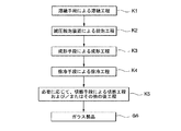
- FIG. 6 is a flowchart of one embodiment of the method for producing a glass product of the present invention.
- the method for producing a glass product of the present invention is characterized by using the aforementioned vacuum degassing apparatus 1.
- the glass product manufacturing method of the present invention includes, as an example, a melting step K1 in which molten glass is manufactured by melting the molten glass in the preceding melting tank 2 of the vacuum degassing apparatus 1 described above, and the vacuum degassing apparatus 1 described above.
- the manufacturing method of the glass product of this invention is performed according to the order of the process of said K1 to K5.
- the method for producing a glass product of the present invention is within the range of known techniques, except that the above-described vacuum degassing apparatus 1 is used.
- a cutting step K5 that is used as necessary, and other subsequent steps
- the process is also shown, depending on the type of glass product, the cutting process K5 and other post processes may not be required.
- the vacuum degassing apparatus 1 of the present invention By performing the vacuum degassing treatment of the molten glass G using the vacuum degassing apparatus 1 of the present invention, a high quality molten glass G with few bubbles can be sent to the molding apparatus 30.
- the extension pipe can be easily replaced with a new long extension pipe when a significant change or adjustment of the degree of vacuum is required due to the difference in the type of glass. Therefore, the vacuum degassing apparatus can be quickly applied to a wider range of the degree of vacuum without modifying the decompression tank, the riser pipe, and the downfall pipe.
- the technology of the present invention can be widely applied to the production of architectural glass, vehicle glass, optical glass, medical glass, display device glass, and other general glass products.
- the entire contents of the specification, claims, drawings, and abstract of Japanese Patent Application No. 2011-078365 filed on March 31, 2011 are incorporated herein as the disclosure of the present invention. .
- G Molten glass (melt), 1 ... Vacuum degassing device, 2 ... Melting tank, 4 ... Cooling jacket, 5 ... Pressure reducing housing, 5A ... Outer wall, 5a, 5b ... Insertion hole, 5d ... Screw hole, 6 ... Pressure reduction Tank (reduced pressure defoaming tank), 7 ... introducing pipe (rising pipe), 8 ... leading pipe (falling pipe), 9 ... extension pipe, 9a ... base end, 9b ... main body, 9c ... sealing flange, 9d ... Outer peripheral edge portion, 9e ... through hole, 9f ... expanded portion, 10 ... heat insulating material, 11 ... inner peripheral portion, 12 ... outer peripheral portion, 13, 14 ...
- seal material 15 ... exterior brick, 16, 16A ... interior brick, 17 ... end brick, 17A ... passage hole, 17a ... large diameter part, 17b ... small diameter part, 17d ... peripheral step part, 18 ... one end opening (lower end opening), 19 ... bolt, 22 ... upstream pit, 23 ... downstream Pit, 20 ... Protective member, 29 ... Extension pipe, 29a ... Base end, 29c ... Spare flange, 29d Flange for sealing, 29g ... bent portion, 29h ... outer peripheral edge portion, 29j ... expanded portion, 29k ... bent portion, 29i ... through hole, 30 ... glass forming device, 33, 34 ... sealing material, 36, 46 ... heat insulating material 50 ... Glass melting furnace, K1 ... Melting step, K2 ... Defoaming step, K3 ... Molding step, K4 ... Slow cooling step, K5 ... Cutting step, G6 ... Glass product.
Landscapes
- Chemical & Material Sciences (AREA)
- Engineering & Computer Science (AREA)
- Materials Engineering (AREA)
- Organic Chemistry (AREA)
- Treatment Of Steel In Its Molten State (AREA)
- Furnace Details (AREA)
- Waste-Gas Treatment And Other Accessory Devices For Furnaces (AREA)
Abstract
Priority Applications (7)
| Application Number | Priority Date | Filing Date | Title |
|---|---|---|---|
| RU2013148540/03A RU2013148540A (ru) | 2011-03-31 | 2012-04-02 | Устройство вакуумной дегазации, устройство для изготовления стеклянных изделий и способ изготовления стеклянных изделий |
| EP12763359.2A EP2692702B1 (fr) | 2011-03-31 | 2012-04-02 | Appareil de dégazage sous vide, appareil pour la production de verrerie et procédé pour la production de verrerie |
| KR1020137018512A KR20140010937A (ko) | 2011-03-31 | 2012-04-02 | 감압 탈포 장치, 유리 제품의 제조 장치, 및 유리 제품의 제조 방법 |
| CN201280014738.2A CN103459333B (zh) | 2011-03-31 | 2012-04-02 | 减压脱泡装置、玻璃制品的制造装置及玻璃制品的制造方法 |
| BR112013024829A BR112013024829A2 (pt) | 2011-03-31 | 2012-04-02 | aparelho de desgaseificação a vácuo, aparelho para produção de objeto de vidro, e método para produção de objeto de vidro |
| JP2013507842A JP5888325B2 (ja) | 2011-03-31 | 2012-04-02 | 減圧脱泡装置、ガラス製品の製造装置、およびガラス製品の製造方法 |
| US14/011,822 US9505645B2 (en) | 2011-03-31 | 2013-08-28 | Vacuum degassing apparatus, apparatus for producing glassware, and method for producing glassware |
Applications Claiming Priority (2)
| Application Number | Priority Date | Filing Date | Title |
|---|---|---|---|
| JP2011078365 | 2011-03-31 | ||
| JP2011-078365 | 2011-03-31 |
Related Child Applications (1)
| Application Number | Title | Priority Date | Filing Date |
|---|---|---|---|
| US14/011,822 Continuation US9505645B2 (en) | 2011-03-31 | 2013-08-28 | Vacuum degassing apparatus, apparatus for producing glassware, and method for producing glassware |
Publications (1)
| Publication Number | Publication Date |
|---|---|
| WO2012133897A1 true WO2012133897A1 (fr) | 2012-10-04 |
Family
ID=46931584
Family Applications (1)
| Application Number | Title | Priority Date | Filing Date |
|---|---|---|---|
| PCT/JP2012/058987 WO2012133897A1 (fr) | 2011-03-31 | 2012-04-02 | Appareil de dégazage sous vide, appareil pour la production de verrerie et procédé pour la production de verrerie |
Country Status (8)
| Country | Link |
|---|---|
| US (1) | US9505645B2 (fr) |
| EP (1) | EP2692702B1 (fr) |
| JP (1) | JP5888325B2 (fr) |
| KR (1) | KR20140010937A (fr) |
| CN (1) | CN103459333B (fr) |
| BR (1) | BR112013024829A2 (fr) |
| RU (1) | RU2013148540A (fr) |
| WO (1) | WO2012133897A1 (fr) |
Cited By (1)
| Publication number | Priority date | Publication date | Assignee | Title |
|---|---|---|---|---|
| JP2019206461A (ja) * | 2018-05-30 | 2019-12-05 | 日本電気硝子株式会社 | ガラス物品の製造方法 |
Families Citing this family (10)
| Publication number | Priority date | Publication date | Assignee | Title |
|---|---|---|---|---|
| WO2016186491A1 (fr) * | 2015-05-15 | 2016-11-24 | Koninklijke Douwe Egberts B.V | Capsule, système de préparation d'une boisson potable à partir d'une telle capsule et utilisation d'une telle capsule dans un dispositif de préparation de boisson |
| CN107848703B (zh) | 2015-05-15 | 2020-03-20 | 皇家戴维艾格伯茨有限公司 | 胶囊、用于从这种胶囊制备饮用饮料的系统以及这种胶囊在饮料制备装置中的使用 |
| KR102596448B1 (ko) | 2015-05-15 | 2023-10-30 | 코닌클리케 도우베 에그베르츠 비.브이. | 캡슐, 이러한 캡슐로부터 마실 수 있는 음료를 제조하기 위한 시스템 및 음료 제조 장치 내의 이러한 캡슐의 이용 |
| EP3134329B9 (fr) | 2015-05-15 | 2019-09-18 | Koninklijke Douwe Egberts B.V. | Capsule, system pour la preparation des boissons et l'usage des capsules |
| KR20180008596A (ko) | 2015-05-15 | 2018-01-24 | 코닌클리케 도우베 에그베르츠 비.브이. | 캡슐, 이러한 캡슐로부터 음용 음료를 제조하기 위한 시스템 및 음료 제조 장치 내의 이러한 캡슐의 이용 방법 |
| WO2016186490A1 (fr) | 2015-05-15 | 2016-11-24 | Koninklijke Douwe Egberts B.V. | Capsule, système de préparation de boisson potable à partir d'une telle capsule, et utilisation d'une telle capsule dans un dispositif de préparation de boisson |
| NL2016780B1 (en) | 2016-05-13 | 2017-11-16 | Douwe Egberts Bv | A capsule, a system for preparing a potable beverage from such a capsule and use of such a capsule in a beverage preparation device |
| NL2016779B1 (en) | 2016-05-13 | 2017-11-16 | Douwe Egberts Bv | A capsule and a system for preparing a potable beverage from such a capsule |
| NL2019254B9 (en) | 2016-10-07 | 2018-09-10 | Douwe Egberts Bv | A capsule, a system for preparing a potable beverage from such a capsule and use of such a capsule in a beverage preparation device |
| NL2019253B1 (en) | 2017-07-14 | 2019-01-28 | Douwe Egberts Bv | Assembly of a capsule and a brew chamber, brew chamber, beverage preparation machine, capsule and use of a capsule. |
Citations (3)
| Publication number | Priority date | Publication date | Assignee | Title |
|---|---|---|---|---|
| JPH11139834A (ja) | 1997-11-07 | 1999-05-25 | Asahi Glass Co Ltd | 溶融ガラスの減圧脱泡装置 |
| JP2003137556A (ja) * | 2001-10-31 | 2003-05-14 | Asahi Glass Co Ltd | 減圧脱泡装置 |
| WO2007020773A1 (fr) * | 2005-08-17 | 2007-02-22 | Asahi Glass Company, Limited | Structure de conduit pour verre fondu |
Family Cites Families (11)
| Publication number | Priority date | Publication date | Assignee | Title |
|---|---|---|---|---|
| JP3767637B2 (ja) * | 1995-08-21 | 2006-04-19 | 旭硝子株式会社 | 高温溶融物用導管の支持構造体 |
| US5897587A (en) * | 1996-12-03 | 1999-04-27 | Atrium Medical Corporation | Multi-stage prosthesis |
| US6119484A (en) * | 1997-10-06 | 2000-09-19 | Asahi Glass Company Ltd. | Vacuum degassing apparatus for molten glass |
| CN1184153C (zh) * | 1998-02-26 | 2005-01-12 | 旭硝子株式会社 | 用于熔融玻璃的抽真空除气装置 |
| DE10117664C1 (de) * | 2001-04-09 | 2002-07-25 | Schott Glas | Rohrstutzen zum Leiten von oder Eintauchen in Glasschmelzen sowie zu deren Erhitzung und die Verwendung des Rohrstutzens |
| EP1298094B1 (fr) | 2001-09-28 | 2007-01-17 | Asahi Glass Company Ltd. | Dispostif pour le dégazage sous vide de verre en fusion |
| KR101242915B1 (ko) * | 2005-03-08 | 2013-03-12 | 아사히 가라스 가부시키가이샤 | 백금 또는 백금 합금제의 구조체 및 이를 이용한 유리 제조장치 |
| KR100922089B1 (ko) * | 2005-08-19 | 2009-10-16 | 아사히 가라스 가부시키가이샤 | 용융 유리의 도관 구조, 및 그 도관 구조를 사용한 감압탈포 장치 |
| WO2008026606A1 (fr) * | 2006-08-29 | 2008-03-06 | Asahi Glass Company, Limited | Structure de conduit pour verre fondu et dégazéificateur sous vide utilisant ladite structure |
| ATE555066T1 (de) * | 2008-02-27 | 2012-05-15 | Asahi Glass Co Ltd | Vorrichtung und methode zur vakuumentgasung von geschmolzenem glas |
| JP5817726B2 (ja) * | 2010-08-04 | 2015-11-18 | 旭硝子株式会社 | 溶融ガラスの導管構造とそれを備えた減圧脱泡装置および溶融ガラスの減圧脱泡方法とガラス製品の製造方法 |
-
2012
- 2012-04-02 KR KR1020137018512A patent/KR20140010937A/ko not_active Application Discontinuation
- 2012-04-02 JP JP2013507842A patent/JP5888325B2/ja active Active
- 2012-04-02 CN CN201280014738.2A patent/CN103459333B/zh active Active
- 2012-04-02 BR BR112013024829A patent/BR112013024829A2/pt not_active IP Right Cessation
- 2012-04-02 WO PCT/JP2012/058987 patent/WO2012133897A1/fr active Application Filing
- 2012-04-02 RU RU2013148540/03A patent/RU2013148540A/ru not_active Application Discontinuation
- 2012-04-02 EP EP12763359.2A patent/EP2692702B1/fr active Active
-
2013
- 2013-08-28 US US14/011,822 patent/US9505645B2/en active Active
Patent Citations (3)
| Publication number | Priority date | Publication date | Assignee | Title |
|---|---|---|---|---|
| JPH11139834A (ja) | 1997-11-07 | 1999-05-25 | Asahi Glass Co Ltd | 溶融ガラスの減圧脱泡装置 |
| JP2003137556A (ja) * | 2001-10-31 | 2003-05-14 | Asahi Glass Co Ltd | 減圧脱泡装置 |
| WO2007020773A1 (fr) * | 2005-08-17 | 2007-02-22 | Asahi Glass Company, Limited | Structure de conduit pour verre fondu |
Cited By (3)
| Publication number | Priority date | Publication date | Assignee | Title |
|---|---|---|---|---|
| JP2019206461A (ja) * | 2018-05-30 | 2019-12-05 | 日本電気硝子株式会社 | ガラス物品の製造方法 |
| WO2019230277A1 (fr) * | 2018-05-30 | 2019-12-05 | 日本電気硝子株式会社 | Procédé de fabrication d'un article en verre |
| JP7118359B2 (ja) | 2018-05-30 | 2022-08-16 | 日本電気硝子株式会社 | ガラス物品の製造方法 |
Also Published As
| Publication number | Publication date |
|---|---|
| CN103459333B (zh) | 2016-08-10 |
| EP2692702B1 (fr) | 2018-10-03 |
| KR20140010937A (ko) | 2014-01-27 |
| EP2692702A1 (fr) | 2014-02-05 |
| EP2692702A4 (fr) | 2014-08-20 |
| US9505645B2 (en) | 2016-11-29 |
| JPWO2012133897A1 (ja) | 2014-07-28 |
| US20130340478A1 (en) | 2013-12-26 |
| JP5888325B2 (ja) | 2016-03-22 |
| CN103459333A (zh) | 2013-12-18 |
| RU2013148540A (ru) | 2015-05-10 |
| BR112013024829A2 (pt) | 2016-12-20 |
Similar Documents
| Publication | Publication Date | Title |
|---|---|---|
| JP5888325B2 (ja) | 減圧脱泡装置、ガラス製品の製造装置、およびガラス製品の製造方法 | |
| JP5595950B2 (ja) | 溶融ガラスを搬送する槽間の結合部を封止する装置 | |
| KR100740392B1 (ko) | 저감된 압력 파이너용 튜빙 시스템 | |
| JP5660029B2 (ja) | ガラス繊維製造用ガラス溶融装置、及びガラス繊維の製造方法 | |
| US7762105B2 (en) | Backup structure for an uprising pipe or downfalling pipe in a vacuum degassing apparatus | |
| US8689588B2 (en) | Glass-melting device for producing glass fiber and method for producing glass fiber using same | |
| KR100922088B1 (ko) | 백금 또는 백금 합금제 중공관의 백업 구조 | |
| TWI389861B (zh) | A platinum or platinum-made structure, a glass-making apparatus, and a vacuum degassing apparatus | |
| US8468851B2 (en) | Vacuum degassing apparatus and vacuum degassing method for molten glass | |
| JP5109086B2 (ja) | 溶融ガラスの導管構造、および該導管構造を用いた減圧脱泡装置 | |
| JP5956009B2 (ja) | ガラス基板の製造方法、ガラス基板製造装置 | |
| JPWO2007020773A1 (ja) | 溶融ガラスの導管構造 | |
| JP3882342B2 (ja) | 溶融ガラスの減圧脱泡装置 | |
| KR20190004284A (ko) | 유리 튜브 제조 장치 및 방법 | |
| KR101493578B1 (ko) | 용융 유리의 감압 탈포 장치 및 감압 탈포 방법 그리고 유리 제품의 제조 장치 및 제조 방법 | |
| KR20200079259A (ko) | 용융 유리 반송 장치, 유리 제조 장치 및 유리 제조 방법 | |
| JP3817868B2 (ja) | 溶融ガラスの減圧脱泡装置 | |
| WO2018211975A1 (fr) | Procédé de production d'articles en verre et four de fusion | |
| JPH11130442A (ja) | 溶融ガラスの減圧脱泡装置 | |
| WO2013024649A1 (fr) | Dispositif de production de verre flotté et procédé de production de verre flotté l'employant | |
| JPWO2012091130A1 (ja) | 清澄槽、ガラス溶融炉、溶融ガラスの製造方法、ガラス製品の製造方法およびガラス製品の製造装置 | |
| KR20030035102A (ko) | 유리용해로용 스로트 |
Legal Events
| Date | Code | Title | Description |
|---|---|---|---|
| 121 | Ep: the epo has been informed by wipo that ep was designated in this application |
Ref document number: 12763359 Country of ref document: EP Kind code of ref document: A1 |
|
| ENP | Entry into the national phase |
Ref document number: 2013507842 Country of ref document: JP Kind code of ref document: A |
|
| ENP | Entry into the national phase |
Ref document number: 20137018512 Country of ref document: KR Kind code of ref document: A |
|
| NENP | Non-entry into the national phase |
Ref country code: DE |
|
| WWE | Wipo information: entry into national phase |
Ref document number: 1301005492 Country of ref document: TH |
|
| ENP | Entry into the national phase |
Ref document number: 2013148540 Country of ref document: RU Kind code of ref document: A |
|
| REG | Reference to national code |
Ref country code: BR Ref legal event code: B01A Ref document number: 112013024829 Country of ref document: BR |
|
| ENP | Entry into the national phase |
Ref document number: 112013024829 Country of ref document: BR Kind code of ref document: A2 Effective date: 20130927 |