WO2012133791A1 - 索条体 - Google Patents
索条体 Download PDFInfo
- Publication number
- WO2012133791A1 WO2012133791A1 PCT/JP2012/058614 JP2012058614W WO2012133791A1 WO 2012133791 A1 WO2012133791 A1 WO 2012133791A1 JP 2012058614 W JP2012058614 W JP 2012058614W WO 2012133791 A1 WO2012133791 A1 WO 2012133791A1
- Authority
- WO
- WIPO (PCT)
- Prior art keywords
- cable
- cover
- annular member
- axial direction
- rope
- Prior art date
- Legal status (The legal status is an assumption and is not a legal conclusion. Google has not performed a legal analysis and makes no representation as to the accuracy of the status listed.)
- Ceased
Links
Images





Classifications
-
- F—MECHANICAL ENGINEERING; LIGHTING; HEATING; WEAPONS; BLASTING
- F16—ENGINEERING ELEMENTS AND UNITS; GENERAL MEASURES FOR PRODUCING AND MAINTAINING EFFECTIVE FUNCTIONING OF MACHINES OR INSTALLATIONS; THERMAL INSULATION IN GENERAL
- F16C—SHAFTS; FLEXIBLE SHAFTS; ELEMENTS OR CRANKSHAFT MECHANISMS; ROTARY BODIES OTHER THAN GEARING ELEMENTS; BEARINGS
- F16C1/00—Flexible shafts; Mechanical means for transmitting movement in a flexible sheathing
- F16C1/10—Means for transmitting linear movement in a flexible sheathing, e.g. "Bowden-mechanisms"
- F16C1/12—Arrangements for transmitting movement to or from the flexible member
- F16C1/14—Construction of the end-piece of the flexible member; Attachment thereof to the flexible member
-
- F—MECHANICAL ENGINEERING; LIGHTING; HEATING; WEAPONS; BLASTING
- F16—ENGINEERING ELEMENTS AND UNITS; GENERAL MEASURES FOR PRODUCING AND MAINTAINING EFFECTIVE FUNCTIONING OF MACHINES OR INSTALLATIONS; THERMAL INSULATION IN GENERAL
- F16C—SHAFTS; FLEXIBLE SHAFTS; ELEMENTS OR CRANKSHAFT MECHANISMS; ROTARY BODIES OTHER THAN GEARING ELEMENTS; BEARINGS
- F16C1/00—Flexible shafts; Mechanical means for transmitting movement in a flexible sheathing
- F16C1/10—Means for transmitting linear movement in a flexible sheathing, e.g. "Bowden-mechanisms"
- F16C1/20—Construction of flexible members moved to and fro in the sheathing
Definitions
- the present invention relates to a striated body for a vehicle having improved assemblability.
- a rope used as a control cable for transmitting an operation performed by a user to a shift lever to a transmission includes an inner cable such as an inner cable that connects the rod of the shift lever and the rod of the transmission, It is comprised by outer ropes, such as an outer casing which penetrates an inner rope so that a movement is possible inside.
- water such as rainwater may enter from between the inner cable and the outer cable at the end portion on the transmission side, and rust may be generated on them. When the rust occurs in this manner, the inner cable becomes difficult to move, and it is difficult to transmit the operation performed by the user to the shift lever to the transmission.
- Patent Literature 1 discloses a rope body in which a waterproof stretchable cover is provided between an inner rope and an outer rope at an end portion on the transmission side. .
- this cable body one end and the other end of the cover are water-tightly pressure-bonded to the inner cable and the outer cable, respectively, thereby preventing water from entering between the inner cable and the outer cable. .
- the present invention has been made in view of the above problems, and an object of the present invention is to provide a cord body with good assemblability.
- the striated body of the present invention is deformed with an inner rope, an outer cable that passes through the inner cable, and a cover that extends between the inner cable and the outer cable.
- the cover has a cover part that covers the distal end side of the cable, and the cover part includes: A pressure-contact portion that press-contacts to the outer surface of the outer rope by deformation of the annular member, and the inclination of the annular member and movement in the axial direction thereof are restricted, and the annular member is moved in the axial direction and the axial direction of the outer rope.
- the holding portion of the cover covering portion that spans the inner rope and the outer rope regulates the inclination of the annular member and the movement in the axial direction thereof,
- the axial direction and the axial direction of the outer rope are held in parallel to each other, and a hard part provided in the covering part adjacent to the holding part suppresses deformation of the holding part.
- the present rope body prevents the annular member from tilting or moving in the axial direction, and deforms the annular member with the covering portion covering the distal end side of the outer rope. Since the press-contact portion of the covering portion can be press-contacted to the outer surface of the outer rope, the operator does not need to adjust the position of the annular member and can be assembled with good assemblability.
- the rigid portion of the cover covering portion is configured to be thicker than the pressure contact portion of the covering portion in a direction perpendicular to the axial direction of the outer rope. Therefore, they can be integrally formed using a mold or the like. Therefore, in this cord body, a cover can be manufactured simply.
- the holding portion of the covering portion of the cover protrudes in a direction perpendicular to the axial direction of the outer rope on both sides so as to sandwich the pressure contact portion of the covering portion, and its protruding thickness Since the thickness of the annular member is larger than the thickness of the annular member, the holding area of the annular member by the holding portion can be increased and the movement of the annular member can be more reliably restricted, so that the assembly can be performed with higher assemblability.
- the annular member after being deformed is accommodated in the accommodating space constituted by the press-contact portion of the covering portion of the cover and the holding portion. It is possible to prevent the annular member from coming off due to an edge of the annular member touching another member.
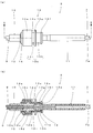
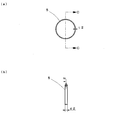
- the enlarged front view of an inner cable (A) An enlarged front view of the outer rope when the inner cable is inserted inside, (b) AA sectional view in (a). (A) The enlarged front view of a cover, (b) BB sectional drawing in (a). (A) Enlarged front view of annular member, (b) CC sectional view in (a). It is a figure explaining an assembly procedure, (a) principal part enlarged front view, (b) DD expanded sectional view in (a). It is a figure explaining an assembly procedure, (a) principal part enlarged front view, (b) EE expanded sectional view in (a). It is a figure which shows the state at the time of an assembly completion, (a) A principal part enlarged front view, (b) FF expanded sectional view in (a).
- the rope 1 of the present invention connects the rod of the transmission TR of the vehicle and the rod of the shift lever SF. As shown in FIG. 1, one end side is the rod of the transmission TR and the other end side is the shift lever.
- An inner cable 2 connected to each of the SF rods, an outer cable 3 through which the inner cable 2 is movably inserted, and a cover 4 provided between the inner cable 2 and the outer cable 3 on one end side;
- An annular member 5 that presses the cover 4 against the outer cable 3 by being deformed is provided.
- the strip 1 is used as a control cable for transmitting an operation performed on the shift lever SF by a vehicle user (not shown) to the rod of the transmission TR.
- the present strip 1 has a feature in the configuration on one end side where the cover 4 is provided, and the following description will focus on the configuration.
- the inner cable 2 has a rod end 7 connected to a rod of the transmission TR connected to one end of an inner cable 6 formed of a metal wire or the like.
- An inner end 8 shown in FIG. 1 for connecting the inner cable 2 to the rod of the shift lever SF is connected to the other end of the inner cable 6.
- the rod end 7 has a cylindrical rod shape, and one end of the inner cable 6 is provided at a guide rod portion 7a connected to the one end and the other end of the guide rod portion 7a.
- 4A and 4B a locking portion 7b for locking the cover 4, and a locking portion 7b provided on the opposite side to the guide rod portion 7a and connected to the rod of the transmission TR.
- an annular mounting portion 7c is provided on the opposite side to the guide rod portion 7a and connected to the rod of the transmission TR.
- the locking portion 7b protrudes in an annular shape from the guide rod portion 7a side end and the attachment portion 7c side end in a direction perpendicular to the axial direction of the rod end 7, respectively.
- the outer cable 3 includes an outer casing 9, a casing cap 10, a guide pipe 11, a socket 13, and a terminal structure 14, as shown in FIGS. 3 (a) and 3 (b).
- the outer casing 9 is configured by stacking a plurality of metal layers and resin layers, and has flexibility.
- the casing cap 10 is fixed by inserting one end of the outer casing 9 to one end side.
- the guide pipe 11 is inserted with a guide rod portion 7a of the rod end 7 shown in FIG.
- the socket 13 connects the other ends of the casing cap 10 and the guide pipe 11 together with the anti-vibration rubber 12 to connect them.
- the terminal structure portion 14 is attached to the other end of the outer casing 9 as shown in FIG.
- the outer rope 3 is configured in a state in which the axial directions of the casing cap 10, the guide pipe 11, the anti-vibration rubber 12, and the socket 13 are matched.
- the outer casing 9 is pipe-shaped as shown in FIG. 3B, and the inner cable 6 shown in FIG. 2 is movably inserted therein.
- the casing cap 10 is formed in a cylindrical shape, and includes a flange portion 10a that protrudes in an annular shape from the outer surface in a direction perpendicular to the axial direction.
- the casing cap 10 has an outer casing fixing portion 10b that opens to one end face provided along the axial direction, and that is inserted and fixed through the outer casing 9, and communicates with the outer casing fixing portion 10b.
- An inner cable insertion portion 10c that opens to the other end side end surface with a smaller diameter and through which the inner cable 6 shown in FIG. 2 is movably inserted is provided.
- the guide pipe 11 is formed in a straight pipe shape, and can move the guide rod portion 7a of the rod end 7 shown in FIG. To be inserted.
- a spherical portion 11 a formed in a spherical shape is formed at the other end of the guide pipe 11.
- the anti-vibration rubber 12 is formed in a cylindrical shape and includes an annular portion 12a that protrudes in an annular shape from the outer surface in a direction perpendicular to the axial direction.
- the anti-vibration rubber 12 includes a casing cap holding portion 12b that opens to one end face provided along the axial direction and holds the flange portion 10a provided on the outer surface of the casing cap 10.
- the anti-vibration rubber 12 includes a guide pipe holding portion 12 c that is a spherical hole that communicates with the casing cap holding portion 12 b and opens to the other end face and holds the spherical portion 11 a of the guide pipe 11.
- the socket 13 has a cylindrical outer diameter portion 13a and a smaller diameter than the large diameter portion 13a, and the large diameter portion 13a and the stepped portion 13c are interposed therebetween.
- a small-diameter portion 13b connected to each other, a through-hole penetrating in the axial direction, and the other end side of the casing cap 10 and a housing portion 13d for housing the spherical portion 11a of the guide pipe 11 together with the antivibration rubber 12. ing.
- the socket 13 has a washer 15 attached to the end surface of the large-diameter portion 13a opposite to the step portion 13c, and the end surface of the small-diameter portion 13b opposite to the step portion 13c with respect to its axial direction.
- a stopper portion 13e that protrudes in an annular shape from the inner surface in the vertical direction is provided.
- the socket 13 includes a flange portion 13f that protrudes in an annular shape from the outer surface of the end portion of the small diameter portion 13b opposite to the step portion 13c in a direction perpendicular to the axial direction. Further, the socket 13 projects in an annular shape from the outer surface of the small diameter portion 13b at a position slightly close to the step portion 13c between the step portion 13c and the flange portion 13f in a direction perpendicular to the axial direction thereof.
- An annular portion 13g is provided. A portion between the flange portion 13f and the annular portion 13g is used as a cover attachment portion 13h for fixing the cover 4, and a portion between the step portion 13c and the annular portion 13g is not shown in the drawing. It is used as a vehicle body fixing portion 13i for fixing the main cable body 1 to the vehicle.
- the cover 4 has a hollow tube shape made of an elastic material such as EPDM (ethylene-propylene-diene rubber) and penetrated between both ends.
- the cover 4 includes a rod end fixing portion 4a for attaching to the locking portion 7b of the rod end 7 shown in FIG. 2, and a bellows portion 4b configured to be extendable and contractable adjacent to the rod end fixing portion 4a.
- the air reservoir 4c that adjusts the air pressure inside the cover 4 by bulging or deflating in accordance with the expansion and contraction of the bellows portion 4b adjacent to the bellows portion 4b, and the air reservoir 4c adjacent to the air reservoir 4c (see FIG. 3).
- It further includes a covering portion 4d that covers the flange portion 13f of the socket 13 and the cover attachment portion 13h shown in a) and (b).
- the rod end fixing portion 4a is formed with an engaging portion 41a protruding in an annular shape from the inner surface in a direction perpendicular to the axial direction.
- the covering portion 4d is formed with an enlarged diameter portion 41d on the inner surface to receive and hold the flange portion 13f of the socket 13 shown in FIG. .
- the covering portion 4d is formed so that the inner diameter of the portion excluding the enlarged diameter portion 41d is smaller than the outer diameter of the cover mounting portion 13h of the socket 13 shown in FIGS.
- two holding portions 43d provided to protrude radially outward from the pressure contact portion 42d, and a rigid portion 44d provided adjacent to the holding portion 43d on the bellows portion 4b side are formed. .
- the pressure contact portion 42d has an annular shape as shown in FIGS. 4 (a) and 4 (b), and the annular member 5 shown in FIGS. 5 (a) and 5 (b) is deformed to deform FIG. It is press-contacted to the cover mounting portion 13h of the socket 13 shown in a) and (b).
- the holding portion 43d is formed to project in an annular shape as shown in FIGS. 4 (a) and 4 (b), and the projecting thickness t1 is an annular member 5 shown in FIGS. 5 (a) and 5 (b). It is thicker than the wall thickness t2.
- the interval d1 formed by the two holding portions 43d is configured to be the same as or slightly wider than the axial width d2 of the annular member 5.
- maintenance part 43d may be formed so that it may protrude annularly so that an outer periphery may become a polygon, and several protrusions may be formed annularly at intervals.
- the hard-to-bend portion 44d is formed to project in an annular shape, and the thickness t3 in the direction perpendicular to the axial direction of the cover 4 is the pressure contact portion. It is thicker than the wall thickness t4 of 42d, so that it is difficult to bend or not bend at all.
- the hard-to-be-hardened portion 44d may be formed so as to project in an annular shape having an outer periphery that is a polygon, or a plurality of projections may be formed in an annular shape at intervals.
- the annular member 5 is made of metal and is formed in a ring shape as shown in FIG.
- the annular member 5 can be deformed by a caulking tool or the like not shown in the drawing, and its inner diameter is formed larger than the outer diameter of the pressure contact portion 42d.
- the cover 4 is provided between the inner cable 2 and the outer cable 3 in FIG.
- the procedure for assembling the one end side that is present will be described.
- the inner cable 2 will be described in a state where the rod end 7 is connected to one end of the inner cable 6 and the inner end 8 is not connected to the other end.
- the annular member 5 is fitted into a space formed by the pressure contact portion 42d of the covering portion 4d of the cover 4 and the two holding portions 43d. As a result, the annular member 5 is externally fitted to the pressure contact portion 42d.
- the cover 4 is fixed to the inner cable 2. This is because the engaging portion 41a provided in the rod end fixing portion 4a of the cover 4 is inserted between the protruding portions 71b and 72b formed in the locking portion 7b of the rod end 7 of the inner cable 2.
- the cover is attached to the cover attaching portion 73b over the entire circumference.
- the inner diameter of the engaging portion 41a of the rod end fixing portion 4a is smaller than the outer diameter of the cover mounting portion 73b, a tightening force is applied to the cover mounting portion 73b in a watertight manner.
- the inner cable 2 with the cover 4 attached is inserted into the outer cable 3.
- This is inserted into one end side of the guide pipe 11 of the outer cable 3 from the other end side of the inner cable 6 of the inner cable 2, and the guide rod portion 7a of the rod end 7 to which one end of the inner cable 6 is fixed is inserted. Do by inserting.
- the cover 4 is externally fitted to the guide pipe 11, and the rod end 7 of the inner cable 2, the casing cap 10 of the outer cable 3, the guide pipe 11, and the anti-vibration rubber 12
- the axial directions of the socket 13 and the cover 4 coincide with each other.
- the annular member 5 hangs down in the accommodation space 45d formed by the pressure contact portion 42d of the cover portion 4d of the cover 4 and the two holding portions 43d.
- the distance d1 is the same as or slightly wider than the axial width d2 of the annular member 5, and the protruding thickness t1 in the direction perpendicular to the axial direction is the annular member 5. It is thicker than 5 wall thickness t2. Therefore, the annular member 5 is maintained in the holding portion 43d in a state where the axial direction thereof is parallel to the axial direction of the outer rope 3, and is prevented from moving in the axial direction.
- the tip side of the outer cable 3 is covered with the cover 4.
- the cover 4 is further moved in the direction of the socket 13 of the outer cable 3, and the small-diameter portion 13 b and the flange portion 13 f of the socket 13 of the outer cable 3 are moved as shown in FIG. This is done by covering with 4d.
- the flange portion 13f formed on the outer surface of the small diameter portion 13b is received by the enlarged diameter portion 41d formed on the inner surface of the covering portion 4d.
- the inner surface of the covering portion 4d closer to the end than the enlarged diameter portion 41d is fitted between the flange portion 13f and the annular portion 13g formed on the outer surface of the socket 13.
- the outer diameter of the cover attaching portion 13h formed between the flange portion 13f and the annular portion 13g is larger than the inner diameter of the portion excluding the enlarged diameter portion 41d of the covering portion 4d.
- the covering portion 4d is pressed by the cover mounting portion 13h to expand in diameter, and is tightly attached to the cover mounting portion 13h by applying a tightening force. Due to the diameter increase of the covering portion 4d, the outer surface of the pressure contact portion 42d of the covering portion 4d abuts against the inner surface of the annular member 5 evenly as shown in FIG.
- the annular member 5 is maintained in a state in which the axial direction of the annular member 5 is parallel to the axial direction of the outer cable 3 and is further prevented from moving in the axial direction.
- the annular member 5 is accommodated in the accommodating space 45d constituted by the pressure contact portion 42d of the covering portion 4d of the cover 4 and the two holding portions 43d.
- the annular member 5 is deformed by deforming it with a tool outside the figure.
- those adjacent to the annular portion 13g side of the socket 13 of the outer rope 3 are brought into contact with the annular portion 13g and deformation is suppressed.
- the thing adjacent to the hard-to-bend part 44d of the said covering part 4d is a deformation
- the pressure contact portion 42d is pressed in a watertight manner on the outer surface of the cover mounting portion 13h of the socket 13.
- the annular member 5 has shown the case where it deform
- the rod end fixing portion 4a of the cover 4 is watertight to the engaging portion 7b of the rod end 7 of the inner rope 2.
- the pressure contact portion 42d of the covering portion 4d of the cover 4 is pressure-contacted with the cover mounting portion 13h of the socket 13 of the outer cable 3 in a watertight manner by the deformation of the annular member 5.
- the holding portion 43d of the covering portion 4d of the cover 4 regulates the inclination of the annular member 5 and the movement in the axial direction thereof. And the axial direction of the outer rope are held in parallel.
- the cable body 1 of the present invention protrudes in a direction perpendicular to the axial direction on both sides so that the holding portion 43d of the covering portion 4d of the cover 4 sandwiches the pressure contact portion 42d of the covering portion 4d, and Since the protruding thickness t1 is thicker than the wall thickness t2 of the annular member 5, the holding area of the annular member 5 by the holding portion 43d can be increased to reliably restrict the movement of the annular member 5.
- the holding portion 43d of the covering portion 4d of the cover 4 adjacent to the annular portion 13g side of the socket 13 of the outer rope 3 is suppressed from being deformed by the annular portion 13g.
- the holding part 43d adjacent to the hard part 44d of the covering part 4d is not shown in order to deform the annular member 5 by the hard part 44d configured to be difficult to bend or not to be bent at all. Deformation by a force applied from a tool or the like is suppressed.
- the rope body 1 of the present invention deforms the annular member 5 in a state where the annular portion 13f and the cover attaching portion 13h of the socket 13 of the outer rope 3 are covered with the covering portion 4d of the cover 4.
- the pressure contact portion 42d of the covering portion 4d is pressure-contacted with the cover mounting portion 13h in a watertight manner, it is not necessary for an operator who performs the assembly work to adjust the position of the annular member 5 before deformation. Can be assembled well.
- the inflexible portion 44d of the cover portion 4d of the cover 4 has a thickness t3 that is perpendicular to the axial direction than the thickness t4 of the pressure contact portion 42d of the cover portion 4d.
- the cover 4 can be manufactured easily because it can be formed integrally using a molding die (not shown) or the like without forming them individually.
- the rope body 1 of the present invention is deformed because the annular member 5 after being deformed is accommodated in the accommodating space 45d constituted by the pressure contact portion 42d of the covering portion 4d of the cover 4 and the two holding portions 43d. It is possible to prevent the annular member 5 from coming off due to the edge of the annular member 5 generated by touching another member or the like.
- the cover portion 4d of the cover 4 excluding the enlarged diameter portion 41d is smaller than the outer diameter of the cover mounting portion 13h of the socket 13, the cover portion 4d allows the cover When the attachment portion 13h is covered, a tightening force is applied from the covering portion 4d to the cover attachment portion 13h so that the attachment portion 13h is in close contact with each other, so that the waterproofness of the portion can be improved.
- the strip 1 shown in the present embodiment is only one aspect of the strip according to the present invention, and various modifications can be made without departing from the gist of the present invention.
- the attachment of the cover 4 to the inner cable 2 may be performed using the annular member 5.
- the rod end fixing portion 4a of the cover 4 is provided with the same configuration as the covering portion 4d.
- the attachment position of the cover 4 to the inner cable 2 and the outer cable 3 is not limited to the above.
- the rod end fixing part 4a of the cover 4 is attached to the guide rod part 7a of the rod end 7 of the inner cable 2 or the like. Also good.
- the striated body according to the present invention can be used as a control cable for a vehicle.
Landscapes
- Engineering & Computer Science (AREA)
- General Engineering & Computer Science (AREA)
- Health & Medical Sciences (AREA)
- Oral & Maxillofacial Surgery (AREA)
- Mechanical Engineering (AREA)
- Flexible Shafts (AREA)
Abstract
内索と、内索を内部に挿通する外索と、内索と外索とに渡設されたカバーと、変形させることでカバーを内索又は外索に圧接する環状部材とを有する索条体において、カバーは、外索の先端側を覆う覆設部を有し、覆設部に、環状部材の変形により外索の外表面へ圧接する圧接部と、環状部材の傾き及びその軸方向の移動を規制して、環状部材をその軸方向と、外索の軸方向とが平行である状態に保持する保持部と、保持部に隣接して、保持部の変形を防止する難撓部とが設けられることを特徴とする索条体。
Description
本発明は、組み立て性を向上した車両用の索条体に関する。
車両において、その利用者がシフトレバーに対し行った操作をトランスミッションに伝達するコントロールケーブルとして使用される索条体は、シフトレバーのロッドとトランスミッションのロッドを連結するインナーケーブル等の内索と、該内索を内部に移動可能に挿通させるアウターケーシング等の外索とにより構成される。この索条体では、トランスミッション側の端部において、雨水等の水が内索と外索の間から侵入して、それらに錆びが生じることがある。このように錆びが生じた場合には、内索が動きにくくなるため、前記利用者がシフトレバーに対し行った操作を、トランスミッションに伝達することが困難となる。
このような状況を鑑みてか、特許文献1には、トランスミッション側の端部において、内索と外索との間に防水性の伸縮可能なカバーを渡設した索条体が開示されている。この索条体では、前記カバーの一端及び他端を、夫々、内索及び外索に水密に圧着することで、内索と外索との間から水が浸入することを防ぐとされている。
しかしながら、特許文献1に開示される索条体では、カバーを、予めそれに外嵌させている環状部材を少なくとも一部が縮径するように変形させて外索に水密に圧接するとされるが、当該カバーの肉厚が薄いので変形しやすく、変形させる前の環状部材の移動可能な範囲も広く構成されている。そのため、この索条体では、作業者が環状部材を変形させるときに、環状部材を圧接させたい位置に調整しつつ行う必要があり、その組み立て性に問題がある。
本発明は、以上のような問題点に鑑みてなされたものであり、組み立て性の良い索条体を提供することを目的とする。
上記目的を達成するために、本発明の索条体は、内索と、該内索を内部に挿通する外索と、前記内索と前記外索とに渡設されたカバーと、変形させることで前記カバーを前記内索又は前記外索に圧接する環状部材とを有する索条体において、前記カバーが、前記外索の先端側を覆う覆設部を有し、該覆設部に、前記環状部材の変形により前記外索の外表面へ圧接する圧接部と、前記環状部材の傾き及びその軸方向の移動を規制して、該環状部材をその軸方向と、前記外索の軸方向とが平行である状態に保持する保持部と、該保持部に隣接する難撓部とが設けられることを特徴としている。
(1)本発明の索条体は、内索と外索とを渡設するカバーの覆設部の保持部が、環状部材の傾き及びその軸方向の移動を規制して、該環状部材をその軸方向と、外索の軸方向とが平行である状態に保持し、更に、前記保持部に隣接して前記覆設部に設けられた難撓部が保持部の変形を抑制する。これにより、本索条体は、環状部材が傾くことや、その軸方向に移動することを防止して、外索の先端側を前記覆設部が覆った状態で、環状部材を変形させて、前記覆設部の圧接部を外索の外表面に圧接できるので、作業者が環状部材の位置を調整する必要がなく、組み立て性良く組み立てを行うことができる。
(2)本発明の索条体では、カバーの覆設部の難撓部が、外索の軸方向に垂直な方向において、前記覆設部の圧接部より肉厚を厚くすることで構成されているので、成形型等を使用して、それらを一体に形成することができる。従って、本索条体では、カバーを簡便に製造することができる。
(3)本発明の索条体では、カバーの覆設部の保持部が、前記覆設部の圧接部を挟むようにその両側で外索の軸方向に垂直な方向に突出し、その突出厚さが前記環状部材の肉厚より厚いので、前記保持部による環状部材の保持面積を大きくして、環状部材の移動をより確実に規制できるので、更に組み立て性良く組み立てを行うことができる。
(4)本発明の索条体では、カバーの覆設部の圧接部と保持部とにより構成される収容空間に、変形させた後の前記環状部材が収容されるので、変形させることにより生じた環状部材のエッジ等が他の部材に触れて、当該環状部材が外れることを防止できる。
(5)本発明の索条体では、カバーの覆設部の内径が外索の外径よりも小さいことにより、前記覆設部により外索の先端部を覆った際に、覆設部から外索に締め付け力が加わることでそれらが密着する。これにより、本索条体では防水性を向上することができる。
以下、図面を参照しつつ、本発明の実施の形態を説明する。本発明の索条体1は、車両のトランスミッションTRのロッドと、シフトレバーSFのロッドを繋ぐものであり、図1に示すように、一端側が前記トランスミッションTRのロッドに、他端側が前記シフトレバーSFのロッドに夫々接続される内索2と、該内索2を内部に移動可能に挿通させる外索3と、一端側において内索2と外索3とに渡設されるカバー4と、変形させることでカバー4を外索3に圧接する環状部材5とを備えている。
本索条体1は、前記図外の車両の利用者が、前記シフトレバーSFに対し行った操作を、前記トランスミッションTRのロッドに伝達するコントロールケーブルとして使用されるものである。本索条体1は、前記カバー4が渡設されている一端側の構成に特徴があり、以下では当該構成を中心に説明を行う。
前記内索2は、図2に示すように、金属ワイヤ等により構成されるインナーケーブル6の一端に前記トランスミッションTRのロッドにつなぐためのロッドエンド7が接続されている。内索2は、前記インナーケーブル6の他端に前記シフトレバーSFのロッドにつなぐための図1に示すインナーエンド8が接続されている。
前記ロッドエンド7は、図2に示すように、円柱棒状であり、前記インナーケーブル6の一端が、その一端に接続されるガイドロッド部7aと、該ガイドロッド部7aの他端に設けられて図4(a),(b)に示すカバー4を係止するための係止部7bと、該係止部7bの前記ガイドロッド部7aと反対側に設けられて前記トランスミッションTRのロッドに接続される円環状の取付部7cとを備える。
前記係止部7bは、図2に示すように、その前記ガイドロッド部7a側端及び前記取付部7c側端から、夫々、ロッドエンド7の軸方向に対し垂直な方向へ円環状に突出する突出部71b,72bと、該突出部71b,72bの間で、ガイドロッド部7aより大径に、且つ、突出部71b,72bよりも小径に形成された円柱状のカバー取付部73bとにより構成される。
前記外索3は、図3(a),(b)に示すように、アウターケーシング9と、ケーシングキャップ10と、ガイドパイプ11と、ソケット13と、端末構造部14とを備える。アウターケーシング9は、金属層と樹脂層とを複数重ねて構成され、可撓性を有する。ケーシングキャップ10は、一端側へ該アウターケーシング9の一端が挿入されて固定される。ガイドパイプ11は、一端より図2に示す前記ロッドエンド7のガイドロッド部7aが挿入される。ソケット13は、前記ケーシングキャップ10と前記ガイドパイプ11の夫々の他端側を防振ゴム12と共に内部に収納することでそれらを連結する。端末構造部14は、図1に示すように、前記アウターケーシング9の他端に取り付けられる。外索3は、前記ケーシングキャップ10、前記ガイドパイプ11、前記防振ゴム12及び前記ソケット13のそれぞれの軸方向を一致させた状態で構成されている。
前記アウターケーシング9は、図3(b)に示すように、パイプ状のものであり、内部に、図2に示す前記インナーケーブル6が移動可能に挿通される。
前記ケーシングキャップ10は、図3(b)に示すように、円筒状に構成されており、その軸方向に対して垂直方向に外表面から円環状に突出するフランジ部10aを備える。ケーシングキャップ10には、その軸方向に沿って設けられた一端側端面に開口し、アウターケーシング9を挿通して固定するアウターケーシング固定部10bと、該アウターケーシング固定部10bと連通して、それより小径に他端側端面へ開口し、図2に示すインナーケーブル6を移動可能に挿通させるためのインナーケーブル挿通部10cとが設けられている。
前記ガイドパイプ11は、図3(b)に示すように、直線パイプ状に構成されており、その内部側に一端より挿入される図2に示す前記ロッドエンド7のガイドロッド部7aを移動可能に挿通させる。ガイドパイプ11の他端には、球状に形成された球状部11aが形成されている。この球状部11aが前記防振ゴム12を介してソケット13に保持されることにより、ガイドパイプ11の一端側は、図3(a),(b)に矢印で示すように、所定範囲で首振りさせることが可能である。
前記防振ゴム12は、図3(b)に示すように、円筒状に構成されており、その軸方向に対して垂直方向に外表面から円環状に突出する円環部12aを備える。防振ゴム12は、その軸方向に沿って設けられた一端側端面に開口し、該ケーシングキャップ10の外表面に備えられたフランジ部10aを保持するケーシングキャップ保持部12bを備える。更に、防振ゴム12は、前記ケーシングキャップ保持部12bと連通して他端側端面へ開口し、前記ガイドパイプ11の球状部11aを保持する球状の孔であるガイドパイプ保持部12cを備える。
前記ソケット13は、図3(a),(b)に示すように、外周が円柱状の大径部13aと、該大径部13aより小径であり、大径部13aと段差部13cを介して連結された小径部13bと、軸方向に沿って貫通した貫通孔でありケーシングキャップ10の他端側、及び、ガイドパイプ11の球状部11aを防振ゴム12と共に収容する収容部13dを備えている。
ソケット13は、前記大径部13aの前記段差部13cとは反対側の端面にワッシャー15が取り付けられると共に、前記小径部13bの前記段差部13cと反対側の端面において、その軸方向に対して垂直方向に内表面から円環状に突出するストッパ部13eが設けられる。これにより、前記収容部13dに収容したケーシングキャップ10の他端側、ガイドパイプ11の球状部11a及び防振ゴム12が収容部13dから外部に抜け出ることが防止される。
ソケット13は、その軸方向に対して垂直方向に、前記小径部13bの前記段差部13cと反対側の端部の外表面から円環状に突出する鍔部13fを備える。更に、ソケット13は、その軸方向に対して垂直方向に、前記段差部13cと前記鍔部13fとの間で、やや段差部13cに近い位置における小径部13bの外表面から円環状に突出する環状部13gを備える。前記鍔部13fと前記環状部13gとの間の部分は前記カバー4を固定するためのカバー取付部13hとして使用され、前記段差部13cと前記環状部13gとの間の部分は前記図外の車両に本索条体1を固定するための車体固定部13iとして使用される。
前記カバー4は、図4(a),(b)に示すように、EPDM(エチレン-プロピレン-ジエンゴム)等の弾性材料により構成された両端間が貫通した中空のチューブ状を呈している。カバー4は、図2に示すロッドエンド7の係止部7bに取り付けるためのロッドエンド固定部4aと、該ロッドエンド固定部4aに隣接して伸縮自在に構成される蛇腹部4bとを有し、該蛇腹部4bに隣接して該蛇腹部4bの伸縮に応じて膨らみ又は萎むことで当該カバー4の内部の空気圧を調整する空気溜り4cと、該空気溜り4cに隣接して図3(a),(b)に示すソケット13の鍔部13fとカバー取付部13hとを覆う覆設部4dとを更に有する。
前記ロッドエンド固定部4aは、図4(b)に示すように、その軸方向に対して垂直方向に内表面から円環状に突出した係合部41aが形成されている。
前記覆設部4dは、図4(b)に示すように、内表面に、図3に示すソケット13の鍔部13fを受け入れて保持するために拡径した拡径部41dが形成されている。覆設部4dは、前記拡径部41dを除く部分の内径が、図3(a),(b)に示すソケット13のカバー取付部13hの外径より小径に形成されている。
前記覆設部4dの外表面には、図5(a),(b)に示す環状部材5が外嵌する圧接部42dと、該圧接部42dの軸方向両側で、カバー4の軸方向に対し垂直な方向に、圧接部42dから半径外側方向へ突出して設けられる2つの保持部43dと、前記蛇腹部4b側の保持部43dに隣接して設けられる難撓部44dとが形成されている。
前記圧接部42dは、図4(a),(b)に示すように円環状であり、外嵌した図5(a),(b)に示す環状部材5を変形させることで、図3(a),(b)に示すソケット13のカバー取付部13hに圧接される。
前記保持部43dは、図4(a),(b)に示すような円環状に突出して形成されており、その突出厚さt1は、図5(a),(b)に示す環状部材5の肉厚t2より厚く構成される。2つの保持部43dがなす間隔d1は、前記環状部材5の軸方向の幅d2と同じ又は僅かに広く構成されている。尚、この保持部43dは、外周が多角形となるような環状に突出して形成してもよく、複数の突起を間隔を空けて環状に形成してもよい。
前記難撓部44dは、図4(a),(b)に示すように円環状に突出して形成されており、そのカバー4の軸方向に対し垂直な方向の肉厚t3は、前記圧接部42dの肉厚t4より厚く、これにより、撓みにくく、或いは全く撓まないように構成されている。尚、この難撓部44dは、外周が多角形となるような環状に突出して形成してもよく、複数の突起を間隔を空けて環状に形成してもよい。
前記環状部材5は、金属製であり、図5に示すように、リング状に形成されるものである。この環状部材5は図外の加締め用工具などにより、変形させることが可能なものであり、その内径は前記圧接部42dの外径よりも大きく形成されている。
以上説明した内索2、外索3、カバー4及び環状部材5を用いて、本発明の索条体1の図1において内索2と外索3との間にカバー4を渡設している一端側を組み立てる手順について説明する。なお、この手順においては、内索2はインナーケーブル6の一端にはロッドエンド7が接続され、他端にはインナーエンド8が接続されていない状態で説明する。
まず、カバー4の覆設部4dの圧接部42dと2つの保持部43dとにより構成される空間に、環状部材5を嵌め込む。これにより、環状部材5が前記圧接部42dに外嵌した状態となる。
次に、カバー4を、内索2に固定する。これは、カバー4のロッドエンド固定部4aに設けられている係合部41aを、内索2のロッドエンド7の係止部7bに形成されている突出部71b,72bの間に挿入して、カバー取付部73bに全周にわたり密着させる。この際、前記ロッドエンド固定部4aの係合部41aは、その内径が前記カバー取付部73bの外径より小さいので、該カバー取付部73bに締め付け力を加えて水密に圧接する。
次に、外索3に、カバー4が取り付けられた内索2を挿通させる。これは、外索3のガイドパイプ11の一端側へ、内索2のインナーケーブル6の他端側から挿入してゆき、インナーケーブル6の一端が固定されたロッドエンド7のガイドロッド部7aを挿入することにより行う。この挿入により、図6(a)に示すように前記ガイドパイプ11に、カバー4が外嵌され、内索2のロッドエンド7、外索3のケーシングキャップ10、ガイドパイプ11、防振ゴム12、ソケット13、及びカバー4の夫々の軸方向が一致するようになる。
上記作業において、図6(a),(b)に示すように、カバー4の覆設部4dの圧接部42dと2つの保持部43dとにより構成される収容空間45dで、環状部材5が垂れ下がることがある。しかしながら、2つの前記保持部43dは、間隔d1が、環状部材5の軸方向の幅d2と同じか僅かに広く、更に、その軸方向に対して垂直な方向の突出厚さt1が、環状部材5の肉厚t2より厚い。そのため、環状部材5は、前記保持部43dに、その軸方向が外索3の軸方向と平行な状態を維持され、且つ、その軸方向に移動することが防止される。
次に、カバー4により外索3の先端側を覆う。これは、カバー4を外索3のソケット13方向に更に移動させて、図7(a)に示すように、外索3のソケット13の小径部13bおよび鍔部13fをカバー4の覆設部4dにより覆わせることにより行う。これにより、前記小径部13bの外表面に形成された鍔部13fは、前記覆設部4dの内表面に形成された拡径部41dに受け入れられる。前記覆設部4dの拡径部41dより端部側の内表面が、前記ソケット13の外表面に形成された鍔部13f,環状部13gとの間に嵌まり込む。この際、前記鍔部13f,環状部13gとの間に形成されている前記カバー取付部13hの外径が、前記覆設部4dの拡径部41dを除く部分の内径より大径であることにより、前記覆設部4dは、前記カバー取付部13hに押圧されて拡径すると共に、該カバー取付部13hに締め付け力を加えて密着する。前記覆設部4dの拡径により、図7(b)に示すように、前記覆設部4dの圧接部42dの外表面が環状部材5の内表面と均等に当接する。これにより、環状部材5は、前記保持部43dに、その軸方向が外索3の軸方向と平行な状態を維持され、且つ、その軸方向に移動することが更に防止される。環状部材5は、この時点でカバー4の覆設部4dの圧接部42dと2つの保持部43dとにより構成される収容空間45dに収容される。
次に、環状部材5を図外の工具などにより変形させることで変形させる。この際、カバー4の覆設部4dの保持部43dのうち、外索3のソケット13の環状部13g側に隣接するものは、当該環状部13gに当接して変形が抑制される。前記覆設部4dの難撓部44dに隣接するものは、当該難撓部44dが、撓みにくく、或いは全く撓まないように構成されていることから、変形が抑制される。従って、環状部材5は、工具などによる変形の際に加わる力により、移動したり傾いたりすることなく変形して、図8(a),(b)に示すように前記覆設部4dに設けられる圧接部42dを、前記ソケット13のカバー取付部13hの外表面に水密に圧接する。
尚、環状部材5は、図8(b)において、6角形に変形させた場合を示しているが、変形後の形状は限定されず任意の形状であってよい。但し、環状部材5の変形は、カバー4の覆設部4dの圧接部42dと2つの保持部43dとにより構成される収容空間45dに変形後の環状部材5が収容されるように行う。
以上のように、前記トランスミッションTRのロッドに接続される一端側が組み立てられる本発明の索条体1は、カバー4のロッドエンド固定部4aが内索2のロッドエンド7の係止部7bに水密に圧接し、カバー4の覆設部4dの圧接部42dが外索3のソケット13のカバー取付部13hに環状部材5の変形により水密に圧接する。これにより、本発明の索条体1は、前記一端側において内索2と外索3との間より水が浸入することを防ぐことができる。
本発明の索条体1は、環状部材5を変形させる前において、カバー4の覆設部4dの保持部43dが、環状部材5の傾き及びその軸方向の移動を規制して、環状部材5の軸方向と、外索の軸方向とが平行である状態に保持する。本発明の索条体1は、カバー4の覆設部4dの保持部43dが、前記覆設部4dの圧接部42dを挟むようにその両側で軸方向に対し垂直な方向に突出し、且つ、その突出厚さt1が環状部材5の肉厚t2より厚いので、前記保持部43dによる環状部材5の保持面積を大きくして、該環状部材5の移動を確実に規制できる。
本発明の索条体1において、外索3のソケット13の環状部13g側に隣接するカバー4の覆設部4dの保持部43dは、当該環状部13gにより変形することが抑制される。前記覆設部4dの難撓部44dに隣接する保持部43dは、撓みにくく、或いは全く撓まないように構成された当該難撓部44dにより、環状部材5を変形させるために前記図外の工具などより加えた力により変形することが抑制される。
以上に基づき、本発明の索条体1は、外索3のソケット13の環状部13f及びカバー取付部13hを、カバー4の覆設部4dが覆った状態で、環状部材5を変形させて前記覆設部4dの圧接部42dを前記カバー取付部13hに水密に圧接させる際に、その組み立て作業を行う作業者が、変形前の環状部材5の位置を調整する必要が無いので、組み立て性よく組み立てを行うことができる。
本発明の索条体1では、カバー4の覆設部4dの難撓部44dが、その肉厚t3を軸方向に垂直な方向において、前記覆設部4dの圧接部42dの肉厚t4より厚くすることにより構成されており、それらを個別に形成することなく、図外の成形型等を用いて一体に成形することができるので、当該カバー4を容易に製造することができる。
本発明の索条体1は、カバー4の覆設部4dの圧接部42dと2つの保持部43dとにより構成される収容空間45dに変形させた後の環状部材5が収容されるので、変形させることにより生じた環状部材5のエッジ等が、他の部材に触れること等により、当該環状部材5が外れることを防止することができる。
本発明の索条体1は、カバー4の覆設部4dの拡径部41dを除く部分の内径が、ソケット13のカバー取付部13hの外径より小さいので、前記覆設部4dにより前記カバー取付部13hを覆った際に、覆設部4dからカバー取付部13hに締め付け力が加わり密着するので、当該部分の防水性を向上させることができる。
尚、本実施の形態で示した索条体1は、本発明に係る索条体の一態様にすぎず、本発明の要旨を逸脱しない範囲内で種々の変形実施が可能である。
例えば、内索2へのカバー4の取り付けは、環状部材5を用いて行ってよい。この場合においては、カバー4のロッドエンド固定部4aに、覆設部4dと同様の構成を設ける。
カバー4の内索2及び外索3への取り付け位置については上記に限定されず、例えばカバー4のロッドエンド固定部4aを、内索2のロッドエンド7のガイドロッド部7aに取り付ける等してもよい。
本発明に係る索条体は、車両用のコントロールケーブルとして使用することができる。
1 索条体
2 内索
3 外索
4 カバー
5 環状部材
4d 覆設部
42d 圧接部
43d 保持部
44d 難撓部
45d 収容空間
2 内索
3 外索
4 カバー
5 環状部材
4d 覆設部
42d 圧接部
43d 保持部
44d 難撓部
45d 収容空間
Claims (5)
- 内索と、
該内索を内部に挿通する外索と、
前記内索と前記外索とに渡設されたカバーと、
変形させることで前記カバーを前記内索又は前記外索に圧接する環状部材とを有する索条体において、
前記カバーは、前記外索の先端側を覆う覆設部を有し、
該覆設部に、前記環状部材の変形により前記外索の外表面へ圧接する圧接部と、
前記環状部材の傾き及びその軸方向の移動を規制して、該環状部材をその軸方向と、前記外索の軸方向とが平行である状態に保持する保持部と、
該保持部に隣接して、該保持部の変形を防止する難撓部とが設けられることを特徴とする索条体。 - 前記難撓部の肉厚は、前記外索の軸方向に垂直な方向において、前記圧接部の肉厚より厚いことを特徴とする請求項1記載の索条体。
- 前記保持部は、前記圧接部を間に挟むように前記圧接部の両側で、前記外索の軸方向に垂直な方向に突出して設けられ、その突出厚さが、前記環状部材の肉厚より厚いことを特徴とする請求項1または2記載の索条体。
- 前記環状部材は、変形させたときに、前記圧接部と前記保持部とにより構成された収容空間に収容されることを特徴とする請求項1,2または3記載の索条体。
- 前記覆設部の内径は、前記外索の外径よりも小さいことを特徴とする請求項1,2,3または4記載の索条体。
Applications Claiming Priority (2)
| Application Number | Priority Date | Filing Date | Title |
|---|---|---|---|
| JP2011-076989 | 2011-03-31 | ||
| JP2011076989A JP2012211624A (ja) | 2011-03-31 | 2011-03-31 | 索条体 |
Publications (1)
| Publication Number | Publication Date |
|---|---|
| WO2012133791A1 true WO2012133791A1 (ja) | 2012-10-04 |
Family
ID=46931486
Family Applications (1)
| Application Number | Title | Priority Date | Filing Date |
|---|---|---|---|
| PCT/JP2012/058614 Ceased WO2012133791A1 (ja) | 2011-03-31 | 2012-03-30 | 索条体 |
Country Status (2)
| Country | Link |
|---|---|
| JP (1) | JP2012211624A (ja) |
| WO (1) | WO2012133791A1 (ja) |
Citations (4)
| Publication number | Priority date | Publication date | Assignee | Title |
|---|---|---|---|---|
| JPH04122821U (ja) * | 1991-04-24 | 1992-11-05 | 豊田合成株式会社 | 等速ジヨイントブーツ |
| JPH0649854U (ja) * | 1992-12-14 | 1994-07-08 | 日本ケーブル・システム株式会社 | コントロ−ルケ−ブル用蛇腹ブ−ツ |
| JP2010001979A (ja) * | 2008-06-20 | 2010-01-07 | Ntn Corp | 等速自在継手 |
| JP2011027247A (ja) * | 2009-07-29 | 2011-02-10 | Hi-Lex Corporation | コントロールケーブルの端末支持装置 |
-
2011
- 2011-03-31 JP JP2011076989A patent/JP2012211624A/ja active Pending
-
2012
- 2012-03-30 WO PCT/JP2012/058614 patent/WO2012133791A1/ja not_active Ceased
Patent Citations (4)
| Publication number | Priority date | Publication date | Assignee | Title |
|---|---|---|---|---|
| JPH04122821U (ja) * | 1991-04-24 | 1992-11-05 | 豊田合成株式会社 | 等速ジヨイントブーツ |
| JPH0649854U (ja) * | 1992-12-14 | 1994-07-08 | 日本ケーブル・システム株式会社 | コントロ−ルケ−ブル用蛇腹ブ−ツ |
| JP2010001979A (ja) * | 2008-06-20 | 2010-01-07 | Ntn Corp | 等速自在継手 |
| JP2011027247A (ja) * | 2009-07-29 | 2011-02-10 | Hi-Lex Corporation | コントロールケーブルの端末支持装置 |
Also Published As
| Publication number | Publication date |
|---|---|
| JP2012211624A (ja) | 2012-11-01 |
Similar Documents
| Publication | Publication Date | Title |
|---|---|---|
| JP5365569B2 (ja) | ワイヤハーネス用のグロメット | |
| EP1258952B1 (en) | Terminal integrated seal member | |
| WO2014024785A1 (ja) | グロメット | |
| KR101335080B1 (ko) | 와이어 하네스용 그로밋 | |
| JP5044508B2 (ja) | コネクタ | |
| JP5098827B2 (ja) | グロメット | |
| JP5167012B2 (ja) | 電線固定部材 | |
| JP5469585B2 (ja) | ワイヤハーネス用のグロメット | |
| JP6574804B2 (ja) | 防水部品 | |
| WO2009147763A1 (ja) | グロメット | |
| WO2015145861A1 (ja) | グロメット及びワイヤーハーネス | |
| JP6259357B2 (ja) | 配管接続構造及び接続部材 | |
| JP7348007B2 (ja) | グロメット | |
| JP5813757B2 (ja) | コントロールケーブル | |
| JP5453166B2 (ja) | グロメット | |
| JP2012211624A (ja) | 索条体 | |
| US9909612B2 (en) | Seal structure | |
| WO2015092830A1 (ja) | コルゲートチューブの保持部材 | |
| JP2017158362A (ja) | グロメット及びグロメット付ワイヤーハーネス | |
| JP2022130819A (ja) | グロメットアセンブリ及びワイヤハーネス | |
| JP4516461B2 (ja) | グロメット | |
| EP3705741A1 (en) | Terminal support device and control cable assembly using terminal support device | |
| JP6839628B2 (ja) | グロメット | |
| JP2017118743A (ja) | グロメットおよび配線モジュール | |
| JP2018196305A (ja) | グロメット |
Legal Events
| Date | Code | Title | Description |
|---|---|---|---|
| 121 | Ep: the epo has been informed by wipo that ep was designated in this application |
Ref document number: 12763375 Country of ref document: EP Kind code of ref document: A1 |
|
| NENP | Non-entry into the national phase |
Ref country code: DE |
|
| 122 | Ep: pct application non-entry in european phase |
Ref document number: 12763375 Country of ref document: EP Kind code of ref document: A1 |