WO2012133531A1 - 金型の加工方法、金型及び光ピックアップ装置用の光学素子 - Google Patents
金型の加工方法、金型及び光ピックアップ装置用の光学素子 Download PDFInfo
- Publication number
- WO2012133531A1 WO2012133531A1 PCT/JP2012/058143 JP2012058143W WO2012133531A1 WO 2012133531 A1 WO2012133531 A1 WO 2012133531A1 JP 2012058143 W JP2012058143 W JP 2012058143W WO 2012133531 A1 WO2012133531 A1 WO 2012133531A1
- Authority
- WO
- WIPO (PCT)
- Prior art keywords
- optical
- axis
- edge
- mold
- light
- Prior art date
- Legal status (The legal status is an assumption and is not a legal conclusion. Google has not performed a legal analysis and makes no representation as to the accuracy of the status listed.)
- Ceased
Links
Images





Classifications
-
- G—PHYSICS
- G11—INFORMATION STORAGE
- G11B—INFORMATION STORAGE BASED ON RELATIVE MOVEMENT BETWEEN RECORD CARRIER AND TRANSDUCER
- G11B7/00—Recording or reproducing by optical means, e.g. recording using a thermal beam of optical radiation by modifying optical properties or the physical structure, reproducing using an optical beam at lower power by sensing optical properties; Record carriers therefor
- G11B7/12—Heads, e.g. forming of the optical beam spot or modulation of the optical beam
- G11B7/135—Means for guiding the beam from the source to the record carrier or from the record carrier to the detector
- G11B7/1353—Diffractive elements, e.g. holograms or gratings
-
- B—PERFORMING OPERATIONS; TRANSPORTING
- B23—MACHINE TOOLS; METAL-WORKING NOT OTHERWISE PROVIDED FOR
- B23B—TURNING; BORING
- B23B1/00—Methods for turning or working essentially requiring the use of turning-machines; Use of auxiliary equipment in connection with such methods
-
- B—PERFORMING OPERATIONS; TRANSPORTING
- B23—MACHINE TOOLS; METAL-WORKING NOT OTHERWISE PROVIDED FOR
- B23B—TURNING; BORING
- B23B27/00—Tools for turning or boring machines; Tools of a similar kind in general; Accessories therefor
- B23B27/14—Cutting tools of which the bits or tips or cutting inserts are of special material
- B23B27/18—Cutting tools of which the bits or tips or cutting inserts are of special material with cutting bits or tips or cutting inserts rigidly mounted, e.g. by brazing
- B23B27/20—Cutting tools of which the bits or tips or cutting inserts are of special material with cutting bits or tips or cutting inserts rigidly mounted, e.g. by brazing with diamond bits or cutting inserts
-
- B—PERFORMING OPERATIONS; TRANSPORTING
- B23—MACHINE TOOLS; METAL-WORKING NOT OTHERWISE PROVIDED FOR
- B23B—TURNING; BORING
- B23B5/00—Turning-machines or devices specially adapted for particular work; Accessories specially adapted therefor
-
- B—PERFORMING OPERATIONS; TRANSPORTING
- B29—WORKING OF PLASTICS; WORKING OF SUBSTANCES IN A PLASTIC STATE IN GENERAL
- B29C—SHAPING OR JOINING OF PLASTICS; SHAPING OF MATERIAL IN A PLASTIC STATE, NOT OTHERWISE PROVIDED FOR; AFTER-TREATMENT OF THE SHAPED PRODUCTS, e.g. REPAIRING
- B29C33/00—Moulds or cores; Details thereof or accessories therefor
- B29C33/42—Moulds or cores; Details thereof or accessories therefor characterised by the shape of the moulding surface, e.g. ribs or grooves
-
- G—PHYSICS
- G11—INFORMATION STORAGE
- G11B—INFORMATION STORAGE BASED ON RELATIVE MOVEMENT BETWEEN RECORD CARRIER AND TRANSDUCER
- G11B7/00—Recording or reproducing by optical means, e.g. recording using a thermal beam of optical radiation by modifying optical properties or the physical structure, reproducing using an optical beam at lower power by sensing optical properties; Record carriers therefor
- G11B7/12—Heads, e.g. forming of the optical beam spot or modulation of the optical beam
- G11B7/135—Means for guiding the beam from the source to the record carrier or from the record carrier to the detector
- G11B7/1365—Separate or integrated refractive elements, e.g. wave plates
- G11B7/1367—Stepped phase plates
-
- G—PHYSICS
- G11—INFORMATION STORAGE
- G11B—INFORMATION STORAGE BASED ON RELATIVE MOVEMENT BETWEEN RECORD CARRIER AND TRANSDUCER
- G11B7/00—Recording or reproducing by optical means, e.g. recording using a thermal beam of optical radiation by modifying optical properties or the physical structure, reproducing using an optical beam at lower power by sensing optical properties; Record carriers therefor
- G11B7/12—Heads, e.g. forming of the optical beam spot or modulation of the optical beam
- G11B7/135—Means for guiding the beam from the source to the record carrier or from the record carrier to the detector
- G11B7/1372—Lenses
- G11B7/1374—Objective lenses
-
- B—PERFORMING OPERATIONS; TRANSPORTING
- B29—WORKING OF PLASTICS; WORKING OF SUBSTANCES IN A PLASTIC STATE IN GENERAL
- B29C—SHAPING OR JOINING OF PLASTICS; SHAPING OF MATERIAL IN A PLASTIC STATE, NOT OTHERWISE PROVIDED FOR; AFTER-TREATMENT OF THE SHAPED PRODUCTS, e.g. REPAIRING
- B29C33/00—Moulds or cores; Details thereof or accessories therefor
- B29C33/38—Moulds or cores; Details thereof or accessories therefor characterised by the material or the manufacturing process
- B29C33/3842—Manufacturing moulds, e.g. shaping the mould surface by machining
-
- G—PHYSICS
- G11—INFORMATION STORAGE
- G11B—INFORMATION STORAGE BASED ON RELATIVE MOVEMENT BETWEEN RECORD CARRIER AND TRANSDUCER
- G11B7/00—Recording or reproducing by optical means, e.g. recording using a thermal beam of optical radiation by modifying optical properties or the physical structure, reproducing using an optical beam at lower power by sensing optical properties; Record carriers therefor
- G11B2007/0003—Recording, reproducing or erasing systems characterised by the structure or type of the carrier
- G11B2007/0006—Recording, reproducing or erasing systems characterised by the structure or type of the carrier adapted for scanning different types of carrier, e.g. CD & DVD
Definitions
- the present invention relates to a mold processing method, a mold, and an optical element for an optical pickup device, and in particular, an optical pickup device capable of recording and / or reproducing (recording / reproducing) information in a compatible manner with different types of optical disks.
- the present invention relates to a mold suitable for molding an optical element for use, a processing method for the mold, and an optical element.
- a laser light source used as a light source for reproducing information recorded on an optical disc and recording information on the optical disc has been shortened.
- a wavelength 390 such as a blue-violet semiconductor laser is used.
- a laser light source of ⁇ 420 nm has been put into practical use.
- these blue-violet laser light sources are used, it is possible to record 15 to 20 GB of information on an optical disk having a diameter of 12 cm when an objective lens having the same numerical aperture (NA) as that of a DVD (digital versatile disk) is used.
- NA of the objective optical element is increased to 0.85, 23 to 25 GB of information can be recorded on an optical disk having a diameter of 12 cm.
- BD Blu-ray Disc
- the BD is an example of an optical disc that uses an NA 0.85 objective lens as described above. Since the coma generated due to the tilt (skew) of the optical disk increases, the BD has a thinner protective substrate (0.1 mm with respect to 0.6 mm of DVD) than the case of the DVD cage, and is caused by skew. The amount of coma is reduced.
- the optical system for BD and the optical system for DVD or CD can be shared. It is preferable to reduce the number of optical components constituting the pickup device as much as possible. And, it is most advantageous to simplify the configuration of the optical pickup device and to reduce the cost to make the objective lens arranged facing the optical disc in common.
- an optical path difference providing structure such as a diffraction structure having a wavelength dependency of spherical aberration in the objective lens. is there.
- Patent Document 1 discloses a technique of cutting a fine groove corresponding to a so-called blazed diffraction grating having a sawtooth cross section using a diamond tool.
- An object of the present invention is to solve the above-described problems, and is a mold for molding an optical element such as an objective lens compatible with three types of optical discs of BD / DVD / CD, for example, It is an object of the present invention to provide a mold processing method, a processed mold, and an optical element transferred from the mold that can suppress a decrease in efficiency of the mold as much as possible.
- a material of a mold for molding an optical element includes a first edge and a second edge extending in a direction intersecting the first edge.
- a machining method of a mold for cutting with a tool having a rake face that is at least partially contoured from The axis of the tool is rotated so that the first edge is farther from the rotation axis of the mold material than the second edge, and the tip of the rake face is separated from the rotation axis.
- Cutting with the first peripheral surface cut by the first edge and the second edge by cutting while rotating the material of the mold with the tool set to be inclined with respect to the axis. And at least a part of a concave annular zone structure having a second peripheral surface.
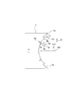
- FIG. 1 is an enlarged view of an optical surface S1 of an objective lens molded from a mold processed by a conventional technique.
- This objective lens has a diffractive structure D having a plurality of annular projections having an inner wall IW and an outer wall OW, and the inner wall IW and the outer wall OW extend in a direction facing each other. ing.
- the parallel light beam L is incident on the objective lens
- the light beam incident on the optical surface other than the inner wall IW and the outer wall OW is used for condensing the optical disk, but is incident on the inner wall IW and the outer wall OW.
- the luminous flux (indicated by hatching) is rarely used for light collection. This is called the shadow effect, and is a factor in reducing efficiency.
- the decrease in efficiency due to the shadow effect is generally negligible with DVD and CD objective lenses, but with a BD / DVD / CD compatible objective lens, etc. It can be said that it is necessary to increase the actual efficiency.
- the inventors focused on the outer wall OW. If the outer wall OW is formed parallel to the optical axis as indicated by the dotted line, it is possible to suppress the parallel light beam from entering the outer wall OW, and accordingly, it is possible to suppress the efficiency reduction of the objective lens.
- the mold is processed so that the outer wall OW is inclined.
- a mold capable of forming an objective lens close to the design state by rotating ( ⁇ ) the axis BX of the rake face of the tool BT within a plane orthogonal to the rotation axis RO.
- a tool having a rake face BT3 that is at least partially contoured from a first edge BT1 and a second edge BT2 extending in a direction intersecting the first edge BT1.
- the BT is formed so that the first edge BT1 is farther from the rotation axis RO of the mold material WK than the second edge BT2, and the tip of the rake face BT3 is separated from the rotation axis RO. Since the material WK is set while being inclined with respect to the rotation axis of the mold material WK, the first peripheral surface OW ′ cut by the first edge portion BT1 can be made substantially parallel to the rotation axis. If the optical element is transferred using such a mold, the outer OIW (see FIG. 1) of the annular groove transferred by the first peripheral surface can be made parallel to the optical axis. Thereby, the efficiency of the optical element can be increased.
- the die machining method according to the first aspect of the invention, wherein the tool axis is set to be inclined with respect to the rotation axis from the outer periphery to the center of the workpiece in the workpiece. It is characterized by cutting with. This saves the labor of setting the tool.
- the mold machining method according to claim 3 is characterized in that an inclination angle of the axis line of the tool with respect to the rotation axis line is changed during cutting of the workpiece portion of the material.
- an inclination angle of the axis line of the tool with respect to the rotation axis line is changed during cutting of the workpiece portion of the material.
- a die machining method according to the third aspect of the invention, wherein the axis of the tool is set in parallel to the rotation axis from the outer periphery to the intermediate portion of the workpiece in the workpiece. Cutting is performed in a state in which the axis of the tool is set to be inclined with respect to the rotation axis from the intermediate portion to the center.
- the effect of the present invention can be expected.
- a die processing method according to any one of the first to fourth aspects, wherein at least a part of the peripheral wall of the concave annular zone structure is at least far from the optical axis of the annular zone structure.
- the peripheral wall on the side is parallel to the optical axis. Since this structure can reduce the effect of shadows due to the outer wall of the annular groove as described above, it is preferable because the efficiency of the optical element can be increased.
- a peripheral wall near the optical axis of the annular structure is inclined with respect to the optical axis.
- the peripheral wall close to the optical axis for example, the inner wall IW in FIG. 1, even if the inner wall is made parallel to the optical axis, the effect of shadow is inevitable. Therefore, the necessity of making the inner wall IW parallel to the optical axis is lower than that of the outer wall OW. Therefore, it is preferable that the inner wall IW is kept inclined with respect to the optical axis, so that a greater degree of freedom can be secured for setting the inclination angle of the tool axis with respect to the rotation axis.
- the tilt angle of the tool axis with respect to the rotation axis is set so that the outer wall is parallel to the optical axis, and it is possible to cut all steps with the tilt angle. Operation becomes easier.
- the mold processing method according to claim 7 is the invention according to any one of claims 1 to 6, wherein the rake face of the tool includes the first edge end and the second edge end.
- a third edge portion having an arc shape connecting the first and second portions, and a radius of the third edge portion is 0.1 to 0.5 ⁇ m.
- the mold machining method according to claim 8 is the invention according to any one of claims 1 to 7, wherein an inclination angle of the axis of the tool with respect to the rotation axis is the first edge and the second. It is characterized in that it is about half the apex angle formed by the edge of each other. With this configuration, since the first edge is parallel to the rotation axis, the step cut at the first edge is easily parallel to the rotation axis.
- an apex angle formed by the first edge portion and the second edge portion is 20-30. It is characterized by °. As a result, interference with the fine shape is reduced, and processing closer to the design shape becomes possible.
- a method for machining a mold according to a tenth aspect is the invention according to the ninth aspect, wherein an inclination angle of the axis of the tool with respect to the rotation axis is 8 to 18 °.
- the mold according to claim 11 is processed by the processing method according to any one of claims 1 to 5.
- the optical element according to claim 12 emits a first light source that emits a first light beam with a first wavelength ⁇ 1 (390 nm ⁇ ⁇ 1 ⁇ 415 nm) and a second light beam with a second wavelength ⁇ 2 (630 nm ⁇ ⁇ 2 ⁇ 670 nm). And a third light source that emits a third light beam having a third wavelength ⁇ 3 (760 nm ⁇ ⁇ 3 ⁇ 820 nm), and a protective substrate having a thickness t1 using the first light beam.
- the third light beam is condensed so that the second light flux passing through the central region is condensed so that information can be recorded and / or reproduced on the information recording surface of the DVD, and the third light beam passing through the central region.
- the light beam is condensed so that information can be recorded and / or reproduced on the information recording surface of the CD, and the first light beam passing through the intermediate area is recorded and / or recorded on the information recording surface of the BD.
- the second light flux that is condensed so that it can be reproduced and passes through the intermediate area is condensed so that information can be recorded and / or reproduced on the information recording surface of the DVD, and the second light flux that passes through the intermediate area
- the third beam is recorded on the information recording surface of the CD.
- the first luminous flux that passes through the peripheral area without being condensed so that it can be reproduced is condensed so that information can be recorded and / or reproduced on the information recording surface of the BD, and the peripheral area
- the second light flux that passes through the peripheral area is not condensed so that information can be recorded and / or reproduced on the information recording surface of the DVD, and the third light flux that passes through the peripheral area is focused on the information recording surface of the CD.
- the central region includes a first optical path difference providing structure, and the first optical path difference providing structure includes a first basic structure having a blazed structure.
- the second foundation structure having a blazed structure is superimposed on each other in the opposite direction, the step of the first foundation structure is directed in the direction opposite to the optical axis, and the step of the second foundation structure is a light Facing the direction of the axis and passing through the first foundation structure
- the first order diffracted light amount of the first light beam is larger than any other order diffracted light amount
- the first order diffracted light amount of the second light beam that has passed through the first basic structure is larger than any other order diffracted light amount.
- the first-order diffracted light amount of the third light beam that has passed through the first basic structure is larger than any other order of diffracted light amount
- the second-order diffracted light amount of the first light beam that has passed through the second basic structure is larger than any other order of diffracted light amount
- the diffracted light quantity is larger than any other order diffracted light quantity
- the first order diffracted light quantity of the second light flux that has passed through the second basic structure is larger than any other order diffracted light quantity
- the first-order diffracted light amount of the third light flux that has passed through the structure is larger than any other order diffracted light amount
- the first optical path difference providing structure has peripheral walls that extend substantially in the optical axis direction and face each other. Has an annular ridge, and at least The peripheral wall on the side farther from the optical axis of the annular convex part is parallel to the optical axis, and the peripheral wall on the side close to the optical axis of the annular convex part is on the annular convex part with respect to the optical axis. It is characterized by tilting away from the optical axis toward the tip.
- the first optical path difference providing structure is a structure in which a first basic structure having a blazed structure and a second basic structure having a blazed structure are overlapped in opposite directions, and the first basic structure is The first-order diffracted light amount of the first light beam that has passed through one basic structure is made larger than any other order of diffracted light amount, and the first-order diffracted light amount of the second light beam that has passed through the first basic structure is set to any other order The first order diffracted light amount of the third light flux that has passed through the first basic structure is made larger than any other order diffracted light amount (hereinafter also referred to as “1/1/1”).
- the second basic structure has a second-order diffracted light amount of the first light beam that has passed through the second basic structure larger than any other order of diffracted light amount, and has passed through the second basic structure.
- Diffraction of any other order for the first-order diffracted light quantity of the light beam A diffractive structure that is larger than the amount of light and that makes the first-order diffracted light amount of the third light beam that has passed through the second basic structure larger than any other order diffracted light amount (hereinafter also referred to as “2/1/1”). It is.
- the first optical path difference is given.
- the step of the structure can be lowered. If the level difference of the optical path difference providing structure can be reduced, the loss of efficiency due to manufacturing errors can be reduced, so that it is possible to obtain an optical element with even higher light utilization efficiency.
- the level difference between the first basic structure having the diffraction structure of “1/1/1” is light.
- the step of the second foundation structure having the diffractive structure of “2/1/1” is directed in the direction opposite to the axis, and is directed in the direction of the optical axis.
- the step of the first basic structure having the diffraction structure of “1/1/1” is directed in the direction of the optical axis
- the step of the second basic structure having the diffraction structure of “2/1/1” is
- the number of peripheral walls on the side farther from the optical axis of the annular zone convex portion of the first optical path difference providing structure is larger than when facing in the direction opposite to the optical axis. Therefore, by making the peripheral wall far from the optical axis of the annular convex part parallel to the optical axis, the loss of efficiency due to the shadow effect is greatly reduced, and ideal light utilization efficiency close to the design value is obtained.
- the present invention becomes more useful.
- the optical element according to claim 13 is the optical element according to claim 12, wherein the annular groove has an optical path difference providing structure.
- the optical element according to claim 14 is characterized in that, in the invention according to claim 12 or 13, the optical element is an objective lens.
- the optical pickup device using the optical element according to the present invention has at least three light sources: a first light source, a second light source, and a third light source. Furthermore, the optical pickup device of the present invention condenses the first light beam on the information recording surface of the BD, condenses the second light beam on the information recording surface of the DVD, and focuses the third light beam on the information recording surface of the CD. A condensing optical system for condensing the light.
- the optical pickup device of the present invention includes a light receiving element that receives a reflected light beam from an information recording surface of a BD, DVD, or CD.
- the BD has a protective substrate having a thickness t1 and an information recording surface.
- the DVD has a protective substrate having a thickness t2 (t1 ⁇ t2) and an information recording surface.
- the CD has a protective substrate having a thickness of t3 (t2 ⁇ t3) and an information recording surface.
- the BD, DVD, or CD may be a multi-layer optical disc having a plurality of information recording surfaces.
- BD means that information is recorded / reproduced by a light beam having a wavelength of about 390 to 415 nm and an objective lens having an NA of about 0.8 to 0.9, and the thickness of the protective substrate is 0.05 to 0.00 mm.
- It is a generic term for a BD series optical disc of about 125 mm, and includes a BD having only a single information recording layer, a BD having two or more information recording layers, and the like.
- DVD is a general term for DVD series optical discs in which information is recorded / reproduced by an objective lens having an NA of about 0.60 to 0.67 and the thickness of the protective substrate is about 0.6 mm.
- CD is a general term for CD series optical discs in which information is recorded / reproduced by an objective lens having an NA of about 0.45 to 0.51 and the thickness of the protective substrate is about 1.2 mm.
- the recording density the recording density of BD is the highest, followed by the order of DVD and CD.
- the thickness of the protective substrate referred to here is the thickness of the protective substrate provided on the surface of the optical disk. That is, the thickness of the protective substrate from the optical disc surface to the information recording surface closest to the surface. 0.050 mm ⁇ t1 ⁇ 0.125 mm (1) 0.5mm ⁇ t2 ⁇ 0.7mm (2) 1.0mm ⁇ t3 ⁇ 1.3mm (3)
- a first light source for BD that emits a light beam with a first wavelength ⁇ 1
- a second light source for DVD that emits a light beam with a second wavelength ⁇ 2
- a first light source for CD that emits a light beam with a third wavelength ⁇ 3.
- the three light sources are preferably laser light sources.
- the laser light source a semiconductor laser, a silicon laser, or the like can be preferably used.
- the wavelength ⁇ 3 ( ⁇ 3> ⁇ 2) preferably satisfies the following conditional expressions (4) and (5). 1.5 ⁇ ⁇ 1 ⁇ 2 ⁇ 1.7 ⁇ ⁇ 1 (4) 1.8 ⁇ ⁇ 1 ⁇ 3 ⁇ 2.0 ⁇ ⁇ 1 (5)
- the first wavelength ⁇ 1 of the first light source is preferably 350 nm to 440 nm, more preferably 390 nm to 415 nm
- the second wavelength ⁇ 2 of the second light source is preferably 570 nm to 680 nm, more preferably.
- the third wavelength ⁇ 3 of the third light source is preferably 750 nm or more and 880 nm or less, more preferably 760 nm or more and 820 nm or less.
- the condensing optical system of the optical pickup device has an objective lens.
- the condensing optical system preferably has a coupling lens such as a collimator in addition to the objective lens.
- the coupling lens is a single lens or a lens group that is disposed between the objective lens and the light source and changes the divergence angle of the light beam.
- the collimator is a type of coupling lens, and is a lens that emits light incident on the collimator as parallel light. These are all optical elements.
- the objective lens refers to an optical system that is disposed at a position facing the optical disk in the optical pickup device and has a function of condensing the light beam emitted from the light source onto the information recording surface of the optical disk.
- the objective lens is preferably a single lens or a plurality of plastic or glass lenses.
- a convex lens is preferable.
- the objective lens preferably has a refractive surface that is aspheric.
- the base surface on which the optical path difference providing structure is provided is preferably an aspherical surface.
- a resin is used as the material of the optical element
- a cycloolefin resin is preferably used.
- ZEONEX manufactured by Nippon Zeon Co., Ltd.
- APEL manufactured by Mitsui Chemicals, Inc.
- ARTON A preferred example is ARTON.
- the Abbe number of the material constituting the objective lens is preferably 50 or more.
- At least one optical surface of the three-compatible objective lens has at least a central region, an intermediate region around the central region, and a peripheral region around the intermediate region.
- the central region is preferably a region including the optical axis of the three-compatible objective lens.
- a minute region including the optical axis is used as an unused region or a special purpose region, and the surrounding region is a central region (also referred to as a central region).
- the central region, the intermediate region, and the peripheral region are preferably provided on the same optical surface. As shown in FIG. 3, it is preferable that the central region CN, the intermediate region MD, and the peripheral region OT are provided concentrically around the optical axis on the same optical surface.
- a three-wavelength shared first optical path difference providing structure is provided in the central area of the 3-compatible objective lens, and a two-wavelength shared second optical path difference providing structure is provided in the intermediate area.
- the peripheral region may be a refracting surface, or a third optical path difference providing structure may be provided in the peripheral region.
- the central region, the intermediate region, and the peripheral region are preferably adjacent to each other, but there may be a slight gap between them.
- the central area of the 3 compatible objective lens can be said to be a preferred BD / DVD / CD shared area when used for recording / reproducing BD, DVD and CD. That is, the 3-compatible objective lens condenses the first light flux that passes through the central area so that information can be recorded / reproduced on the information recording surface of the BD, and the second light flux that passes through the central area becomes the DVD. It is preferable that the light is condensed on the information recording surface so that information can be recorded / reproduced, and the third light flux passing through the central region is condensed so that information can be recorded / reproduced on the information recording surface of the CD.
- the first optical path difference providing structure provided in the central region has the BD protective substrate thickness t1 and the DVD protective substrate thickness with respect to the first and second light fluxes passing through the first optical path difference providing structure. It is preferable to correct spherical aberration generated due to the difference in thickness t2 / spherical aberration generated due to the difference in wavelength between the first light beam and the second light beam. Further, the first optical path difference providing structure is different from the thickness t1 of the BD protective substrate and the thickness t3 of the CD protective substrate with respect to the first and third light fluxes that have passed through the first optical path difference providing structure. It is preferable to correct the spherical aberration caused by the difference in the wavelength of the first light beam and the third light beam.
- the intermediate area of the 3 compatible objective lens is used for BD and DVD recording / reproduction, and can be said to be a preferable BD / DVD common area when not used for CD recording / reproduction. That is, the 3-compatible objective lens condenses the first light flux passing through the intermediate area so that information can be recorded / reproduced on the information recording surface of the BD, and the second light flux passing through the intermediate area is converted into the DVD. It is preferable to collect light so that information can be recorded / reproduced on the information recording surface. On the other hand, it is preferable that the third light flux passing through the intermediate region is not condensed so that information can be recorded / reproduced on the information recording surface of the CD.
- the third light flux that passes through the intermediate region of the three-compatible objective lens preferably forms a flare on the information recording surface of the CD.
- the light amount density is changed in the order from the optical axis side (or the center of the spot) to the outside. It is preferable to have a high spot central portion SCN, a spot intermediate portion SMD whose light intensity density is lower than that of the spot central portion, and a spot peripheral portion SOT whose light intensity density is higher than that of the spot intermediate portion and lower than that of the spot central portion.
- the center portion of the spot is used for recording / reproducing information on the optical disc, and the middle portion of the spot and the peripheral portion of the spot are not used for recording / reproducing information on the optical disc.
- this spot peripheral part is called flare.
- the spot peripheral part may be called a flare. Good.
- the third light flux that has passed through the intermediate region of the three-compatible objective lens preferably forms a spot peripheral portion on the information recording surface of the CD.
- the peripheral area of the 3 compatible objective lens is used for BD recording / reproduction, and can be said to be a preferable BD-dedicated area when not used for DVD / CD recording / reproduction. That is, it is preferable that the three-compatible objective lens condenses the first light beam passing through the peripheral region so that information can be recorded / reproduced on the information recording surface of the BD. On the other hand, the second light flux that passes through the peripheral area is not condensed so that information can be recorded / reproduced on the information recording surface of the DVD, and the third light flux that passes through the peripheral area does not converge. It is preferable not to collect light so that information can be recorded / reproduced.
- the second light flux and the third light flux that pass through the peripheral area of the 3-compatible objective lens preferably form a flare on the information recording surface of DVD and CD. That is, it is preferable that the second light flux and the third light flux that have passed through the peripheral area of the three-compatible objective lens form a spot peripheral portion on the information recording surface of the DVD and CD.
- the first optical path difference providing structure is preferably provided in a region of 70% or more of the area of the central region of the three-compatible objective lens, and more preferably 90% or more. More preferably, the first optical path difference providing structure is provided on the entire surface of the central region.
- the second optical path difference providing structure is preferably provided in a region of 70% or more of the area of the intermediate region of the three-compatible objective lens, and more preferably 90% or more. More preferably, the second optical path difference providing structure is provided on the entire surface of the intermediate region.
- the third optical path difference providing structure is preferably provided in an area of 70% or more of the area of the peripheral area of the 3-compatible objective lens, and 90% or more is provided. More preferred. More preferably, the third optical path difference providing structure is provided on the entire surface of the peripheral region.
- the optical path difference providing structure referred to in this specification is a general term for a structure that adds an optical path difference to an incident light beam, and has an annular groove.
- the optical path difference providing structure also includes a phase difference providing structure for providing a phase difference.
- the phase difference providing structure includes a diffractive structure.
- the optical path difference providing structure of the present invention is preferably a diffractive structure.
- the optical path difference providing structure has a step, preferably a plurality of steps. This step adds an optical path difference and / or phase difference to the incident light flux.
- the optical path difference added by the optical path difference providing structure may be an integer multiple of the wavelength of the incident light beam or a non-integer multiple of the wavelength of the incident light beam.
- the steps may be arranged with a periodic interval in the direction perpendicular to the optical axis, or may be arranged with a non-periodic interval in the direction perpendicular to the optical axis.
- the objective lens provided with the optical path difference providing structure is a single aspherical lens
- the incident angle of the light flux to the objective lens differs depending on the height from the optical axis.
- Each will be slightly different.
- the objective lens is a single-lens aspherical convex lens, even if it is an optical path difference providing structure that provides the same optical path difference, generally the distance from the optical axis tends to increase.
- the diffractive structure referred to in this specification is a general term for structures that have a step and have a function of converging or diverging a light beam by diffraction.
- a plurality of unit shapes are arranged around the optical axis, and a light beam is incident on each unit shape, and the wavefront of the transmitted light is shifted between adjacent annular zones, resulting in new It includes a structure that converges or diverges light by forming a simple wavefront.
- the diffractive structure preferably has a plurality of steps, and the steps may be arranged with a periodic interval in the direction perpendicular to the optical axis, or may be arranged with a non-periodic interval in the direction perpendicular to the optical axis.
- the objective lens provided with the diffractive structure is a single aspherical lens
- the incident angle of the light beam to the objective lens differs depending on the height from the optical axis, so the step amount of the diffractive structure is slightly different for each annular zone. It will be.
- the objective lens is a single aspherical convex lens, even if it is a diffractive structure that generates diffracted light of the same diffraction order, generally, the distance from the optical axis tends to increase.
- the optical path difference providing structure has a plurality of concentric annular zones with the optical axis as the center.
- the optical path difference providing structure can generally have various cross-sectional shapes (cross-sectional shapes on the plane including the optical axis), and the cross-sectional shapes including the optical axis are roughly classified into a blazed structure and a staircase structure.
- the blaze-type structure means that the cross-sectional shape including the optical axis of the optical element having the optical path difference providing structure is a sawtooth shape.
- the upper side is the light source side and the lower side is the optical disk side, and the optical path difference providing structure is formed on a plane as a mother aspherical surface.
- the length in the direction perpendicular to the optical axis of one blaze unit is called a pitch P.
- the length of the step in the direction parallel to the optical axis of the blaze is referred to as a step amount B.
- FIG. 5A In such a single blazed structure, there are no peripheral walls facing each other.
- the staircase structure has a cross-sectional shape including an optical axis of an optical element having an optical path difference providing structure (referred to as a staircase unit). ).
- V level means a ring-shaped surface (hereinafter also referred to as a terrace surface) corresponding to (or facing) the vertical direction of the optical axis in one step unit of the step structure. In other words, it is divided by V steps and divided into V ring zones.
- a three-level or higher staircase structure has a small step and a large step.
- the optical path difference providing structure illustrated in FIG. 5C is referred to as a five-level step structure
- the optical path difference providing structure illustrated in FIG. 5D is referred to as a two-level step structure (also referred to as a binary structure). .
- the optical path difference providing structure is preferably a structure in which a certain unit shape is periodically repeated.
- the unit shape is periodically repeated here naturally includes shapes in which the same shape is repeated in the same cycle.
- the unit shape that is one unit of the cycle has regularity, and the shape in which the cycle gradually increases or decreases gradually is also included in the “unit shape is periodically repeated”.
- first optical path difference providing structure and the second optical path difference providing structure may be provided on different optical surfaces of the objective lens, but are preferably provided on the same optical surface.
- the first optical path difference providing structure, the second optical path difference providing structure, and the third optical path difference providing structure are preferably provided on the light source side surface of the objective lens rather than the surface of the objective lens on the optical disk side.
- the first optical path difference providing structure, the second optical path difference providing structure, and the third optical path difference providing structure are preferably provided on the optical surface having the smaller absolute value of the radius of curvature of the objective lens. It is also conceivable to provide the first basic structure and the second basic structure on different optical surfaces without overlapping. Similarly, the third basic structure and the fourth basic structure may be provided on different optical surfaces without overlapping.
- the optical path difference providing structure may be a structure in which a plurality of basic structures (for example, the first basic structure and the second basic structure in FIG. 6D) are overlapped.
- FIG. 6 shows the first optical path difference providing structure ODS1 as a flat plate for convenience, it may be provided on a single aspherical convex lens.
- the second-order diffracted light quantity of the first light beam that has passed through the second basic structure is made larger than any other order of diffracted light quantity, and the first-order diffracted light quantity of the second light beam that has passed through the second basic structure is set to any other order.
- the first-order diffracted light amount of the third light beam that has passed through the second basic structure is larger than any other order diffracted light amount (“2/1/1”).
- the first-order diffracted light quantity of the first light beam that has passed through the first basic structure is made larger than the diffracted light quantity of any other order in the two basic structure BS2, and the first-order diffraction of the second light beam that has passed through the first basic structure.
- the light quantity is made larger than any other order diffracted light quantity
- the first order diffracted light quantity of the third light flux that has passed through the first basic structure is made larger than any other order diffracted light quantity (“1/1/1”). )
- An example in which the first basic structure BS1 that is a diffractive structure is overlaid. . In FIG.
- the step of the second foundation structure BS2 faces the direction of the optical axis OA
- the step of the first foundation structure BS1 faces the direction opposite to the optical axis OA. Furthermore, it can be seen that the positions of all the steps of the second foundation structure BS2 are aligned with the positions of the steps of the first foundation structure BS1.
- the step of the second foundation structure BS2 faces the direction of the optical axis OA
- the step of the first foundation structure BS1 also faces the direction of the optical axis OA. Furthermore, it can be seen that the positions of all the steps of the second foundation structure BS2 are aligned with the positions of the steps of the first foundation structure BS1.
- step difference of 1st foundation structure BS1 has faced the direction opposite to optical axis OA
- step difference of 2nd foundation structure BS2 has also faced the direction opposite to optical axis OA.
- the positions of all the steps of the second foundation structure BS2 are aligned with the positions of the steps of the first foundation structure BS1.
- FIGS. 5 (c), (d) This refers to the structure shown in FIG.
- NA1 is preferably 0.75 or more and 0.9 or less, and more preferably 0.8 or more and 0.9 or less.
- NA1 is preferably 0.85.
- NA2 is preferably 0.55 or more and 0.7 or less.
- NA2 is preferably 0.60 or 0.65.
- NA3 is preferably 0.4 or more and 0.55 or less.
- NA3 is preferably 0.45 or 0.53.
- the boundary between the central region and the intermediate region of the objective lens is 0.9 ⁇ NA 3 or more and 1.2 ⁇ NA 3 or less (more preferably 0.95 ⁇ NA 3 or more, 1.15 ⁇ NA 3) when the third light beam is used. It is preferably formed in a portion corresponding to the following range. More preferably, the boundary between the central region and the intermediate region of the objective lens is formed in a portion corresponding to NA3. Further, the boundary between the intermediate region and the peripheral region of the objective lens is 0.9 ⁇ NA 2 or more and 1.2 ⁇ NA 2 or less (more preferably 0.95 ⁇ NA 2 or more, 1.15) when the second light flux is used. -It is preferably formed in a portion corresponding to the range of NA2 or less. More preferably, the boundary between the intermediate region and the peripheral region of the objective lens is formed in a portion corresponding to NA2.
- the spherical aberration has at least one discontinuous portion.
- the discontinuous portion has a range of 0.9 ⁇ NA 3 or more and 1.2 ⁇ NA 3 or less (more preferably 0.95 ⁇ NA 3 or more and 1.15 ⁇ NA 3 or less) when the third light flux is used. It is preferable that it exists in.
- the present invention is particularly suitable for an objective lens used in a thin slim type optical pickup device. Since the objective lens used in the slim type optical pickup device inevitably has a small diameter, the pitch of the annular zone is also reduced, making it difficult to process. For this reason, the effects of the present invention are more conspicuous, and the effect of the present invention with less loss of light utilization efficiency becomes more remarkable.
- the objective lens used in the slim type optical pickup device preferably has a diameter in the direction perpendicular to the optical axis of the entire objective lens including the flange and the optical surface in the range of 1.45 mm to 4.05 mm. More preferably, it is 2.95 mm or more and 4.05 mm or less. Moreover, it is preferable that the minimum value of the pitch of the optical path difference providing structure in the direction perpendicular to the optical axis is 2.5 ⁇ m or more and 10 ⁇ m or less. The maximum pitch value is preferably 110 ⁇ m or less. Furthermore, it is preferable that the total number of zones of the optical path difference providing structure in the entire objective lens is 150 or more and 250 or less.
- the tool used in the present invention includes a rake face that is at least partially contoured from a first edge and a second edge extending in a direction intersecting the first edge.
- the first edge is farther from the rotation axis of the mold material than the second edge.
- the first edge and the second edge may be directly connected with the tool axis as a boundary, or may be connected via a third edge that crosses the tool axis.
- the first edge and the second edge are each preferably straight, but a part of the first edge may be arcuate.
- a mold for molding an optical element such as an objective lens compatible with three types of optical disks of BD / DVD / CD, which can suppress a decrease in efficiency of the optical element as much as possible.
- Methods, processed molds, and optical elements transferred from the molds can be provided.
- FIG. 1 It is a figure which shows a diamond tool
- (a) is a perspective view which shows the cutting edge of the diamond tool used with the processing method of the metal mold
- (b) is an enlarged view which shows the front-end
- a BD / DVD / CD compatible objective lens is designed using optical design software such as codeV. Then, the mold is processed based on the design result.
- FIG.7 (a) is a perspective view which shows the cutting edge of the diamond tool used with the processing method of the metal mold
- FIG.7 (b) is an enlarged view which shows the front-end
- the cutting edge 3 of the diamond tool is brazed to the shank S as shown in the figure, and has a rake face 3a that faces the rotational direction of the mold to be cut.
- the tip of the rake face 3a connects the edge 3b as the first edge and the edge 3c as the second edge with the end A of the edge 3b and the end B of the edge 3c. It is contoured from the arc part 3d which is the third edge.
- the scissor angle (vertical angle) between the first edge 3b and the second edge 3c is preferably 20 to 30 ° (preferably 29 ° or less).
- the bisector of the first edge 3b and the second edge 3c is defined as the axis BX of the tool 3.
- FIG. 8 is a perspective view of an XZB-axis ultra-precision lathe used for mold machining.
- FIG. 9 is an enlarged cross-sectional view when cutting a mold using a diamond tool.
- a rotation drive mechanism 9 is provided on a Z-axis stage 5 that is movable in the Z-axis direction with respect to the surface plate 10, and the rotation drive mechanism 9 rotates the mold material 1 to be cut. It is designed to rotate around the axis AX.
- a B-axis stage 11 that can rotate about the B-axis is provided on the surface plate 10, and an X-axis stage 6 that is movable in the X direction is provided on the B-axis stage 11.
- the optical transfer surface can be processed by moving it relative to the material 1.
- the mold material 1 uses an iron-based base material, and after roughing the required shape with respect to the cutting surface, electroless nickel plating is applied as a processing layer to a thickness of about 50 ⁇ m. .
- the shape required for the optical surface (surface to be processed) 1a of the mold material 1 is the diffractive optical surface shape of the BD / DVD / CD compatible plastic objective lens.
- the mold material 1 is rotated at, for example, 1000 revolutions per minute, and the X-axis stage 6 and the Z-axis stage 5 are controlled by program control so that the tip of the diamond tool 3 is indicated by the arrow in FIG.
- the translational movement is performed from the outer peripheral side toward the central portion at a moving speed of 0.1 mm per minute so as to obtain a desired diffractive optical surface shape.
- the bisector BX (see FIG. 7B) of the apex angle of the diamond tool 3 is tilted with respect to the rotation axis AX of the mold material 1 and the outer periphery. Cutting from center to center.
- the inclination angle of the bisector BX of the apex angle with respect to the rotation axis is about half of the apex angle. In this case, the angle is 8 ° to 18 °.
- the first edge 3b (however, depending on the tilt angle, cutting may be performed at the third edge 3d, but in this case, cutting is performed on the side far from the rotation axis across the tool axis.
- the peripheral surface (first peripheral surface) closer to the optical axis in the ring-shaped convex portion 1d (first peripheral surface) (in the concave portion, the peripheral surface away from the optical axis) 1b can be formed parallel to the rotation axis AX.
- the objective lens when the objective lens is molded using a die cut by such processing, the objective lens whose peripheral wall (corresponding to the outer wall OW in FIG. 1) on the side far from the optical axis of the annular convex portion is parallel to the optical axis. Can be formed.
- the second edge 3c forms a circumferential surface (second circumferential surface) 1c far from the optical axis in the annular projection 1d (a circumferential surface closer to the optical axis in the concave portion) 1c. it can. That is, when the objective lens is formed using a die cut by such processing, the peripheral wall (corresponding to the inner wall IW in FIG. 1) on the side closer to the optical axis of the annular convex portion is annular convex with respect to the optical axis. It is possible to form an objective lens that is inclined away from the optical axis toward the tip of the part.
- the first edge 3b does not have to be strictly parallel to the rotation axis AX.
- the diamond tool 3 is closer to the optical axis by relative movement in the Z direction. This is because the peripheral surface 1b on the side can be formed parallel to the rotation axis AX.
- the bisector BX of the apex angle of the diamond tool 3 is set to the rotational axis AX of the mold material 1 from the outer periphery to the middle part of the machining surface 1a of the mold material 1. Cutting is performed in a parallel state, and then the diamond tool 3 is rotated about the B axis in FIG. 8. From the middle part to the center, the bisector BX of the apex angle of the diamond tool 3 is set as a mold. Cutting can also be performed by changing the angle to a state in which the material 1 is tilted with respect to the rotation axis AX.
- the first edge 3b can form the circumferential surface 1b on the side close to the optical axis of the ring-shaped convex portion 1d in a range from the intermediate portion to the center in parallel to the rotation axis AX. That is, when an objective lens is molded using a die cut by such processing, an objective lens in which the peripheral wall near the optical axis of the annular groove is parallel to the optical axis in the range from the intermediate portion to the center can be formed. .
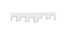
- FIGS. 10 and 11 show an enlarged cross-sectional shape of a part of a mold to be processed, and the shape of the mold is indicated by hatching.
- the inventors divided the bisector of the apex angle of the diamond tool 3 into the bisector of the apex angle of the diamond tool 3 and the comparative mold that does not incline with respect to the rotation axis AX of the mold material 1.
- Each of the molds of the example in which the line BX was inclined with respect to the rotation axis AX of the mold material 1 was manufactured, and an objective lens having a compatible diffraction structure was molded by both molds.
- diffraction efficiency of the objective lens molded from the comparative mold was measured, diffraction efficiency when using BD: 74.1%, diffraction efficiency when using DVD: 56.4%, diffraction efficiency when using CD: 52 It was 1%.
- the optical element is not limited to an objective lens.
Landscapes
- Engineering & Computer Science (AREA)
- Mechanical Engineering (AREA)
- Physics & Mathematics (AREA)
- Optics & Photonics (AREA)
- Optical Head (AREA)
- Moulds For Moulding Plastics Or The Like (AREA)
- Turning (AREA)
- Diffracting Gratings Or Hologram Optical Elements (AREA)
Abstract
例えばBD/DVD/CDの3種類の光ディスク互換用の対物レンズ等の光学素子を成形する金型であって、光学素子の効率低下を極力抑えることができる金型の加工方法、加工された金型、及び金型から転写された光学素子を提供する。直線状の第1の縁部と該第1の縁部に交差する方向に延在する第2の縁部とから少なくとも一部が輪郭づけられるすくい面を備えた工具にて、前記第1の縁部を回転軸線に対して傾けてセットした工具により前記素材を切削することにより、前記第1の縁部により切削された第1の周面が回転軸線と平行になるので、かかる金型を用いて光学素子を転写すれば、前記第1の周面が光軸と平行にできる。
Description
本発明は、金型の加工方法、金型及び光ピックアップ装置用の光学素子に関し、特に異なる種類の光ディスクに対して互換可能に情報の記録及び/又は再生(記録/再生)を行える光ピックアップ装置用の光学素子を成形するのに好適な金型、その金型の加工方法及び光学素子に関する。
近年、光ピックアップ装置において、光ディスクに記録された情報の再生や、光ディスクへの情報の記録のための光源として使用されるレーザ光源の短波長化が進み、例えば、青紫色半導体レーザ等、波長390~420nmのレーザ光源が実用化されている。これら青紫色レーザ光源を使用すると、DVD(デジタルバーサタイルディスク)と同じ開口数(NA)の対物レンズを使用する場合で、直径12cmの光ディスクに対して、15~20GBの情報の記録が可能となり、対物光学素子のNAを0.85にまで高めた場合には、直径12cmの光ディスクに対して、23~25GBの情報の記録が可能となる。
上述のようなNA0.85の対物レンズを使用する光ディスクの例として、BD(ブルーレイディスク)が挙げられる。光ディスクの傾き(スキュー)に起因して発生するコマ収差が増大するため、BDでは、DVD における場合よりも保護基板を薄く設計し(DVDの0.6mmに対して、0.1mm)、スキューによるコマ収差量を低減している。
ところで、BDに対して適切に情報の記録/再生ができると言うだけでは、光ディスクプレーヤ/レコーダ(光情報記録再生装置)の製品としての価値は十分なものとはいえない。現在において、多種多様な情報を記録したDVDやCD(コンパクトディスク)が販売されている現実をふまえると、BDに対して情報の記録/再生ができるだけでは足らず、例えばユーザが所有しているDVDやCDに対しても同様に適切に情報の記録/再生ができるようにすることが、BD用の光ディスクプレーヤ/レコーダとしての商品価値を高めることに通じるのである。このような背景から、BD用の光ディスクプレーヤ/レコーダに搭載される光ピックアップ装置は、BDとDVD、更にはCDの何れに対しても互換性を維持しながら適切に情報を記録/再生できる性能を有することが望まれる。
BDとDVD、更にはCDの何れに対しても互換性を維持しながら適切に情報を記録/再生できるようにする方法として、BD用の光学系とDVDやCD用の光学系とを情報を記録/再生する光ディスクの記録密度に応じて選択的に切り替える方法が考えられるが、複数の光学系が必要となるので、小型化に不利であり、またコストが増大する。
従って、光ピックアップ装置の構成を簡素化し、低コスト化を図るためには、互換性を有する光ピックアップ装置においても、BD用の光学系とDVDやCD用の光学系とを共通化して、光ピックアップ装置を構成する光学部品点数を極力減らすのが好ましい。そして、光ディスクに対向して配置される対物レンズを共通化することが光ピックアップ装置の構成の簡素化、低コスト化に最も有利となる。尚、記録/再生波長が互いに異なる複数種類の光ディスクに対して共通な対物レンズを得るためには、球面収差の波長依存性を有する回折構造等の光路差付与構造を対物レンズに形成する必要がある。
ところで、このような対物レンズの光路差付与構造は、一般的に微細な構造であるため、金型の加工が難しいという問題がある。これに対し特許文献1には、ダイヤモンド工具を用いて断面が鋸歯状の、いわゆるブレーズ形状の回折格子に対応する微細溝を切削加工する技術が開示されている。
ところで、本発明者らの研究によれば、上述した特許文献1の技術にて微細溝を加工した場合、例えばBD/DVD/CD互換用の対物レンズにおける設計上の効率に対し、実際に加工した金型により転写成形された対物レンズの実効率の低下が大きいことが判明した。特に、単なるブレーズ形状ではなく、略光軸方向に延在し互いに向かい合う周壁を備えた構造において特に実効率の低下が著しいことも見出した。例えば、DVDやCD等においても、光路差付与構造を有する対物レンズは用いられているが、特許文献1の技術にて微細溝の加工を行っても、設計効率に対して実効率は、特に著しい低下は見られないという実情がある。
本発明は、上述の課題を解決することを目的としたものであり、例えばBD/DVD/CDの3種類の光ディスク互換用の対物レンズ等の光学素子を成形する金型であって、光学素子の効率低下を極力抑えることができる金型の加工方法、加工された金型、及び金型から転写された光学素子を提供することを目的とする。
請求項1に記載の金型の加工方法は、光学素子を成形する金型の素材を、第1の縁部と該第1の縁部に交差する方向に延在する第2の縁部とから少なくとも一部が輪郭づけられるすくい面を備えた工具にて切削する金型の加工方法において、
前記第1の縁部が、前記第2の縁部よりも金型の素材の回転軸線より遠い位置になり、且つ前記すくい面の先端が回転軸線より離れるように、前記工具の軸線を前記回転軸線に対して傾けてセットした前記工具により、金型の素材を回転させながら切削することにより、前記第1の縁部により切削された第1の周面と、前記第2の縁部により切削された第2の周面とを有する凹状の輪帯構造を少なくとも一部形成することを特徴とする。
前記第1の縁部が、前記第2の縁部よりも金型の素材の回転軸線より遠い位置になり、且つ前記すくい面の先端が回転軸線より離れるように、前記工具の軸線を前記回転軸線に対して傾けてセットした前記工具により、金型の素材を回転させながら切削することにより、前記第1の縁部により切削された第1の周面と、前記第2の縁部により切削された第2の周面とを有する凹状の輪帯構造を少なくとも一部形成することを特徴とする。
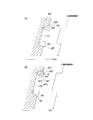
本発明者は、鋭意研究により、実際の対物レンズにて効率が低下する理由を解析した。その結果、以下のことが判明した。図1は、従来の技術により加工した金型より成形した対物レンズの光学面S1の拡大図である。この対物レンズは、内側壁IWと外側壁OWとを有する輪帯凸部を複数個備えた回折構造Dを有しており、内側壁IWと外側壁OWとは対向し合う方向に延在している。ここで、対物レンズに平行光束Lを入射させたとき、内側壁IWと外側壁OW以外の光学面に入射した光束は、光ディスクの集光に用いられるが、内側壁IWと外側壁OWに入射した光束(ハッチングで示す)は、集光に用いられることはほとんどない。これを影の効果といい、効率低下の要因となっている。しかるに、影の効果による効率低下は、DVDやCD用の対物レンズでは一般的に無視できるが、BD/DVD/CD互換用の対物レンズなどでは、各波長の光束で効率を取り合いになるため、より実効率を高める必要があるといえる。
ここで、本発明者らは、外側壁OWに着目した。点線で示すように外側壁OWを光軸に対して平行に形成すれば、平行光束が外側壁OWに入射することが抑制され、その分、対物レンズの効率低下を抑制できる。ところが、従来技術によれば、図1に示すように外側壁OWが傾くような金型の加工が行われていたのである。
より具体的に説明すると、模式図である図2(a)において、金型の素材WKに対して、工具の軸線BXを回転軸線と平行とした状態で切削する従来技術の例である。従来技術では、切削用のダイヤモンド工具BTの軸線BXを、素材WKの回転軸線ROと平行に設定していたので、輪帯状の凹部PJの外側壁OW’が、ダイヤモンド工具BTのすくい面の縁部に沿って、工具先端に向かうに連れて回転軸線に近づくように傾いてしまっていた。このような切削加工により形成された金型を用いて対物レンズを転写成形すると、図1に示すように外側壁OWが光軸に対して傾いた輪帯溝が形成されるのである。
そこで本発明者らは、以上の知見に基づいて、工具BTのすくい面を回転させて、回折効率を向上させることを思いついたのである。つまり、図2(b)に示すように、回転軸線ROに直交する面内で、工具BTのすくい面の軸線BXを回転(θ)させれば、設計状態に近い対物レンズを成形できる金型を加工できるのである。より具体的には、第1の縁部BT1と該第1の縁部BT1に交差する方向に延在する第2の縁部BT2とから少なくとも一部が輪郭づけられるすくい面BT3を備えた工具BTを、第1の縁部BT1が、第2の縁部BT2よりも金型の素材WKの回転軸線ROより遠い位置になり、且つすくい面BT3の先端が回転軸線ROより離れるように、金型の素材WKの回転軸線に対して傾けてセットして、素材WKを切削することにより、第1の縁部BT1により切削された第1の周面OW’を回転軸線と略平行にできるので、かかる金型を用いて光学素子を転写すれば、その第1の周面により転写された輪帯溝の外側OIW(図1参照)を光軸と平行にできる。これにより光学素子の効率を高めることができるのである。
請求項2に記載の金型の加工方法は、請求項1に記載の発明において、前記素材の被加工部における外周から中央まで、前記工具の軸線を前記回転軸線に対して傾けてセットした状態で切削することを特徴とする。これにより、前記工具の設定の手間が省ける。
請求項3に記載の金型の加工方法は、前記工具の軸線の前記回転軸線に対する傾き角を、前記素材の被加工部の切削途中で変更することを特徴とする。このような構成にすることによって、例えばブレーズ型構造しかない領域は、工具の軸線を回転軸線に平行にし、互いに向かい合う周壁を有する凹部を有する領域では、工具の軸線を回転軸線に対して傾ける等、構造に応じて最も好ましい工具の軸線の角度で切削でき、より設計形状に近い金型を得ることが可能となり、光の利用効率をさらに向上できるため好ましい。
請求項4に記載の金型の加工方法は、請求項3に記載の発明において、前記素材の被加工部における外周から中間部まで、前記工具の軸線を前記回転軸線に平行にセットした状態で切削し、前記中間部から中央まで、前記工具の軸線を前記回転軸線に対して傾けてセットした状態で切削することを特徴とする。特に光学素子の中央付近は、互換用の光路差付与構造を有していることが多いので、本発明の効果が期待できる。
請求項5に記載の金型の加工方法は、請求項1乃至4のいずれかに記載の発明において、少なくとも一部の凹状の輪帯構造の周壁において、少なくとも前記輪帯構造の光軸から遠い側の周壁は、光軸に対して平行であることを特徴とする。本構成によって上述のように輪帯溝の外側壁による影の効果を低減できるため、光学素子の効率を高めることができ好ましい。
請求項6に記載の金型の加工方法は、請求項5に記載の発明において、少なくとも前記輪帯構造の光軸に近い側の周壁は、光軸に対して傾いていることを特徴とする。光軸に近い側の周壁、例えば、図1でいうところの内側壁IWにおいては、例え、内側壁を光軸と平行にしたとしても、影の効果は避けられない。従って、内側壁IWを光軸に対して平行にする必要性は、外側壁OWに比して低い。そのため、内側壁IWは、光軸に対して傾いたままとすることにより、工具の軸線の回転軸線に対する傾け角の設定についてより多くの自由度を確保することができ、好ましい。例えば、工具の軸線の回転軸線に対する傾け角を、外側壁が光軸に平行になるように設定し、その傾け角のまま、全段差を切削することも可能となるため、切削中の工具の操作がより容易となる。
請求項7に記載の金型の加工方法は、請求項1乃至6のいずれかに記載の発明において、前記工具のすくい面は、前記第1の縁部端部と前記第2の縁部端部とを結ぶ円弧状の第3の縁部を有し、前記第3の縁部の半径は、0.1~0.5μmであることを特徴とする。これにより、加工のダレが減少し、微細な構造を精度良く加工できる。
請求項8に記載の金型の加工方法は、請求項1乃至7のいずれかに記載の発明において、前記工具の軸線の前記回転軸線に対する傾け角が、前記第1の縁部と前記第2の縁部とがなす頂角の約半分であることを特徴とする。本構成によって、第1の縁部が回転軸線に対して平行となるため、第1の縁部で切削した段差を回転軸線に対して平行にしやすくなる。
請求項9に記載の金型の加工方法は、請求項1乃至8のいずれかに記載の発明において、前記第1の縁部と前記第2の縁部とがなす頂角は、20~30°であることを特徴とする。これにより、微細形状への干渉が減少し、より設計形状に近い加工が可能になる。
請求項10に記載の金型の加工方法は、請求項9に記載の発明であって、前記工具の軸線の前記回転軸線に対する傾け角が、8~18°であることを特徴とする。
請求項11に記載の金型は、請求項1乃至5のいずれかに記載の加工方法により加工されたことを特徴とする。
請求項12に記載の光学素子は、第1波長λ1(390nm≦λ1≦415nm)の第1光束を射出する第1光源と、第2波長λ2(630nm≦λ2≦670nm)の第2光束を射出する第2光源と、第3波長λ3(760nm≦λ3≦820nm)の第3光束を射出する第3光源とを有し、前記第1光束を用いて厚さがt1の保護基板を有するBDの情報の記録及び/又は再生を行い、前記第2光束を用いて厚さがt2(t1<t2)の保護基板を有するDVDの情報の記録及び/又は再生を行い、前記第3光束を用いて厚さがt3(t2<t3)の保護基板を有するCDの情報の記録及び/又は再生を行う光ピックアップ装置において用いられる光学素子であって、前記光学素子の少なくとも一つの光学面は、中央領域と、中央領域の周りの中間領域と、中間領域の周りの周辺領域とを少なくとも有し、前記光学素子は、前記中央領域を通過する前記第1光束を、BDの情報記録面上に情報の記録及び/又は再生ができるように集光し、前記中央領域を通過する前記第2光束を、DVDの情報記録面上に情報の記録及び/又は再生ができるように集光し、前記中央領域を通過する前記第3光束を、CDの情報記録面上に情報の記録及び/又は再生ができるように集光し、前記中間領域を通過する前記第1光束を、BDの情報記録面上に情報の記録及び/又は再生ができるように集光し、前記中間領域を通過する前記第2光束を、DVDの情報記録面上に情報の記録及び/又は再生ができるように集光し、前記中間領域を通過する前記第3光束を、CDの情報記録面上に情報の記録及び/又は再生ができるように集光せず、前記周辺領域を通過する前記第1光束を、BDの情報記録面上に情報の記録及び/又は再生ができるように集光し、前記周辺領域を通過する前記第2光束を、DVDの情報記録面上に情報の記録及び/又は再生ができるように集光せず、前記周辺領域を通過する前記第3光束を、CDの情報記録面上に情報の記録及び/又は再生ができるように集光せず、前記中央領域は、第1光路差付与構造を備え、前記第1光路差付与構造は、ブレーズ型構造を有する第1基礎構造とブレーズ型構造を有する第2基礎構造を互いに逆向きに重ね合わせた構造であり、前記第1基礎構造の段差は光軸とは逆の方向を向いており、前記第2基礎構造の段差は光軸の方向を向いており、前記第1基礎構造を通過した前記第1光束の1次の回折光量は他のいかなる次数の回折光量よりも大きくなり、前記第1基礎構造を通過した前記第2光束の1次の回折光量は他のいかなる次数の回折光量よりも大きくなり、前記第1基礎構造を通過した前記第3光束の1次の回折光量は他のいかなる次数の回折光量よりも大きくなり、前記第2基礎構造を通過した前記第1光束の2次の回折光量は他のいかなる次数の回折光量よりも大きくなり、前記第2基礎構造を通過した前記第2光束の1次の回折光量は他のいかなる次数の回折光量よりも大きくなり、前記第1基礎構造を通過した前記第3光束の1次の回折光量は他のいかなる次数の回折光量よりも大きくなり、前記第1光路差付与構造は、略光軸方向に延在し互いに向かい合う周壁を備えた輪帯凸部を有し、少なくとも前記輪帯凸部の光軸から遠い側の周壁は、光軸に対して平行であり、前記輪帯凸部の光軸に近い側の周壁は、光軸に対して前記輪帯凸部の先端に向かうにつれて光軸から離れるように傾いていることを特徴とする。
光軸に近い側の周壁は、理想形状であっても、影の効果による効率ロスを免れないため、理想形状にしなくても光量のロスはあまり変化がない。つまり、光軸に近い側の傾きによる効率の寄与度は、光軸から遠い側の周壁の傾きによる効率の寄与度より小さい。そのため、輪帯凸部の光軸に近い側の周壁を傾けていることにより、工具の角度をあまりに細かく制御する必要がなく、製造しやすく、それでいて、影の効果による光利用効率のロスを大きくすることはない。また、輪帯凸部の光軸に近い側の周壁を、光軸に対して輪帯凸部の先端に向かうにつれて光軸から離れるように傾けていることにより、射出成形の際、金型から光学素子をスムーズに離型できため成形性を良くできる。更に、輪帯凸部の光軸から遠い側の周壁を光軸に平行にすることにより、影の効果による効率のロスを大幅に低減でき、設計値に近い理想的な光利用効率を得ることが可能となる。即ち、製造及び成形しやすく、それでいて、光利用効率の高い光学素子を得ることが可能となるのである。
また、第1光路差付与構造は、ブレーズ型構造を有する第1基礎構造とブレーズ型構造を有する第2基礎構造を互いに逆向きに重ね合わせた構造であり、かつ、第1基礎構造は、第1基礎構造を通過した第1光束の1次の回折光量を他のいかなる次数の回折光量よりも大きくし、第1基礎構造を通過した第2光束の1次の回折光量を他のいかなる次数の回折光量よりも大きくし、第1基礎構造を通過した第3光束の1次の回折光量を他のいかなる次数の回折光量よりも大きくする(以下、「1/1/1」とも記載する。)回折構造であり、前記第2基礎構造は、第2基礎構造を通過した第1光束の2次の回折光量を他のいかなる次数の回折光量よりも大きくし、第2基礎構造を通過した第2光束の1次の回折光量を他のいかなる次数の回折光量よりも大きくし、第2基礎構造を通過した第3光束の1次の回折光量を他のいかなる次数の回折光量よりも大きくする(以下、「2/1/1」とも記載する)回折構造である。このように、ブレーズ型構造を有する「1/1/1」の回折構造とブレーズ型構造を有する「2/1/1」の回折構造を互いに逆向きに重ね合わせた場合、第1光路差付与構造の段差を低くすることできる。光路差付与構造の段差を低くできると、製造誤差による効率のロスを低減できるため、よりいっそう光利用効率の高い光学素子を得ることが可能となる。
また、ブレーズ型構造を有する第1基礎構造とブレーズ型構造を有する第2基礎構造を互いに逆向きに重ね合わせる際、「1/1/1」の回折構造を有する第1基礎構造の段差は光軸とは逆の方向を向いていて、「2/1/1」の回折構造を有する第2基礎構造の段差は光軸の方向を向いている。この場合、「1/1/1」の回折構造を有する第1基礎構造の段差が光軸の方向を向いていて、「2/1/1」の回折構造を有する第2基礎構造の段差が光軸とは逆の方向を向いている場合に比べて、第1光路差付与構造が有する輪帯凸部の光軸から遠い側の周壁の数が多くなる。そのため、輪帯凸部の光軸から遠い側の周壁を光軸に平行にすることにより、影の効果による効率のロスを大幅に低減し、設計値に近い理想的な光利用効率を得るという本発明がより有用となる。
請求項13に記載の光学素子は、請求項12に記載の発明において、前記輪帯溝は光路差付与構造であることを特徴とする。
請求項14に記載の光学素子は、請求項12又は13に記載の発明において、前記光学素子は対物レンズであることを特徴とする。
本発明に係る光学素子が用いられる光ピックアップ装置は、第1光源、第2光源、第3光源の少なくとも3つの光源を有する。さらに、本発明の光ピックアップ装置は、第1光束をBDの情報記録面上に集光させ、第2光束をDVDの情報記録面上に集光させ、第3光束をCDの情報記録面上に集光させるための集光光学系を有する。また、本発明の光ピックアップ装置は、BD、DVD又はCDの情報記録面からの反射光束を受光する受光素子を有する。
BDは、厚さがt1の保護基板と情報記録面とを有する。DVDは厚さがt2(t1<t2)の保護基板と情報記録面とを有する。CDは、厚さがt3(t2<t3)の保護基板と情報記録面とを有する。なお、BD、DVD又はCDは、複数の情報記録面を有する複数層の光ディスクでもよい。
本明細書において、BDとは、波長390~415nm程度の光束、NA0.8~0.9程度の対物レンズにより情報の記録/再生が行われ、保護基板の厚さが0.05~0.125mm程度であるBD系列光ディスクの総称であり、単一の情報記録層のみ有するBDや、2層又はそれ以上の情報記録層を有するBD等を含むものである。更に、本明細書においては、DVDとは、NA0.60~0.67程度の対物レンズにより情報の記録/再生が行われ、保護基板の厚さが0.6mm程度であるDVD系列光ディスクの総称であり、DVD-ROM、DVD-Video、DVD- Audio、DVD-RAM、DVD-R、DVD-RW、DVD+R、DVD+RW等を含む。また、本明細書においては、CDとは、NA0.45~0.51程度の対物レンズにより情報の記録/再生が行われ、保護基板の厚さが1.2mm 程度であるCD系列光ディスクの総称であり、CD-ROM、CD-Audio、CD-Video、CD-R、CD-RW等を含む。尚、記録密度については、BDの記録密度が最も高く、次いでDVD、CDの順に低くなる。
なお、保護基板の厚さt1、t2、t3に関しては、以下の条件式(1)、(2)、(3)を満たすことが好ましいが、これに限られない。尚、ここで言う、保護基板の厚さとは、光ディスク表面に設けられた保護基板の厚さのことである。即ち、光ディスク表面から、表面に最も近い情報記録面までの保護基板の厚さのことをいう。
0.050mm ≦ t1 ≦ 0.125mm (1)
0.5mm ≦ t2 ≦ 0.7mm (2)
1.0mm ≦ t3 ≦ 1.3mm (3)
0.050mm ≦ t1 ≦ 0.125mm (1)
0.5mm ≦ t2 ≦ 0.7mm (2)
1.0mm ≦ t3 ≦ 1.3mm (3)
本明細書において、第1波長λ1の光束を出射するBD用の第1光源、第2波長λ2の光束を出射するDVD用の第2光源、第3波長λ3の光束を出射するCD用の第3光源は、好ましくはレーザ光源である。レーザ光源としては、好ましくは半導体レーザ、シリコンレーザ等を用いることが出来る。第1光源から出射される第1光束の第1波長λ1、第2光源から出射される第2光束の第2波長λ2(λ2>λ1)、第3光源から出射される第3光束の第3波長λ3(λ3>λ2)は以下の条件式(4)、(5) を満たすことが好ましい。
1.5・λ1 < λ2 < 1.7・λ1 (4)
1.8・λ1 < λ3 < 2.0・λ1 (5)
1.5・λ1 < λ2 < 1.7・λ1 (4)
1.8・λ1 < λ3 < 2.0・λ1 (5)
第1光源の第1波長λ1は好ましくは、350nm 以上、440nm以下、より好ましくは、390nm以上、415nm以下であって、第2光源の第2波長λ2は好ましくは570nm以上、680nm以下、より好ましくは、630nm以上、670nm以下であって、第3光源の第3波長λ3は好ましくは、750nm以上、880nm以下、より好ましくは、760nm以上、820nm以下である。
光ピックアップ装置の集光光学系は、対物レンズを有する。集光光学系は、対物レンズの他にコリメータ等のカップリングレンズを有していることが好ましい。カップリングレンズとは、対物レンズと光源の間に配置され、光束の発散角を変える単レンズ又はレンズ群のことをいう。コリメータは、カップリングレンズの一種で、コリメータに入射した光を平行光にして出射するレンズである。これらはいずれも光学素子である。本明細書において、対物レンズとは、光ピックアップ装置において光ディスクに対向する位置に配置され、光源から射出された光束を光ディスクの情報記録面上に集光する機能を有する光学系を指す。また、対物レンズは、単玉又は複数枚からなるプラスチック又はガラス製のレンズであることが好ましい。好ましくは、凸レンズである。また、対物レンズは、屈折面が非球面であることが好ましい。また、対物レンズは、光路差付与構造が設けられるベース面が非球面であることが好ましい。
光学素子の素材に樹脂を用いる場合、シクロオレフィン樹脂が好適に用いられ、具体的には、日本ゼオン社製のZEONEXや、三井化学社製のAPEL、TOPAS ADVANCED POLYMERS社製のTOPAS、JSR社製ARTONなどが好ましい例として挙げられる。
また、対物レンズを構成する材料のアッベ数は、50以上であることが好ましい。
3互換用対物レンズについて、以下に記載する。3互換用対物レンズの少なくとも一つの光学面が、中央領域と、中央領域の周りの中間領域と、中間領域の周りの周辺領域とを少なくとも有する。中央領域は、3互換用対物レンズの光軸を含む領域であることが好ましいが、光軸を含む微小な領域を未使用領域や特殊な用途の領域とし、その周りを中心領域(中央領域ともいう)としてもよい。中央領域、中間領域、及び周辺領域は同一の光学面上に設けられていることが好ましい。図3に示されるように、中央領域CN、中間領域MD、周辺領域OTは、同一の光学面上に、光軸を中心とする同心円状に設けられていることが好ましい。また、3互換用対物レンズの中央領域には3波長共用の第一光路差付与構造が設けられ、中間領域には2波長共用の第二光路差付与構造が設けられている。周辺領域は屈折面であってもよいし、周辺領域に第三光路差付与構造が設けられていてもよい。中央領域、中間領域、周辺領域はそれぞれ隣接していることが好ましいが、間に僅かに隙間があっても良い。
3互換用対物レンズの中央領域は、BD、DVD及びCDの記録/再生に用いられると好ましいBD/DVD/CD共用領域と言える。即ち、3互換用対物レンズは、中央領域を通過する第1光束を、BDの情報記録面上に情報の記録/再生ができるように集光し、中央領域を通過する第2光束を、DVDの情報記録面上に情報の記録/再生ができるように集光し、中央領域を通過する第3光束を、CDの情報記録面上に情報の記録/再生ができるように集光すると好ましい。また、中央領域に設けられた第1光路差付与構造は、第1光路差付与構造を通過する第1光束及び第2光束に対して、BDの保護基板の厚さt1とDVDの保護基板の厚さt2の違いにより発生する球面収差/第1光束と第2光束の波長の違いにより発生する球面収差を補正することが好ましい。さらに、第1光路差付与構造は、第1光路差付与構造を通過した第1光束及び第3光束に対して、BDの保護基板の厚さt1とCDの保護基板の厚さt3との違いにより発生する球面収差/第1光束と第3光束の波長の違いにより発生する球面収差を補正することが好ましい。
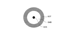
3互換用対物レンズの中間領域は、BD、DVDの記録/再生に用いられ、CDの記録/再生に用いられないと好ましいBD/DVD共用領域と言える。即ち、3互換用対物レンズは、中間領域を通過する第1光束を、BDの情報記録面上に情報の記録/再生ができるように集光し、中間領域を通過する第2光束を、DVDの情報記録面上に情報の記録/再生ができるように集光すると好ましい。その一方で、中間領域を通過する第3光束を、CDの情報記録面上に情報の記録/再生ができるように集光しないと好ましい。3互換用対物レンズの中間領域を通過する第3光束は、CDの情報記録面上でフレアを形成することが好ましい。図4に示すように、3互換用対物レンズを通過した第3光束がCDの情報記録面上で形成するスポットにおいて、光軸側(又はスポット中心部)から外側へ向かう順番で、光量密度が高いスポット中心部SCN、光量密度がスポット中心部より低いスポット中間部SMD、光量密度がスポット中間部よりも高くスポット中心部よりも低いスポット周辺部SOTを有することが好ましい。スポット中心部が、光ディスクの情報の記録/再生に用いられ、スポット中間部及びスポット周辺部は、光ディスクの情報の記録/再生には用いられない。上記において、このスポット周辺部をフレアと言っている。但し、スポット中心部の周りにスポット中間部が存在せずスポット周辺部があるタイプ、即ち、集光スポットの周りに薄く光が大きなスポットを形成する場合も、そのスポット周辺部をフレアと呼んでもよい。つまり、3互換用対物レンズの中間領域を通過した第3光束は、CDの情報記録面上でスポット周辺部を形成することが好ましいとも言える。
3互換用対物レンズの周辺領域は、BDの記録/再生に用いられ、DVD及びCDの記録/再生に用いられないと好ましいBD専用領域と言える。即ち、3互換用対物レンズは、周辺領域を通過する第1光束を、BDの情報記録面上に情報の記録/再生ができるように集光すると好ましい。その一方で、周辺領域を通過する第2光束を、DVDの情報記録面上に情報の記録/再生ができるように集光せず、周辺領域を通過する第3光束を、CDの情報記録面上に情報の記録/再生ができるように集光しないと好ましい。3互換用対物レンズの周辺領域を通過する第2光束及び第3光束は、DVD及びCDの情報記録面上でフレアを形成することが好ましい。つまり、3互換用対物レンズの周辺領域を通過した第2光束及び第3光束は、DVD及びCDの情報記録面上でスポット周辺部を形成することが好ましい。
第1光路差付与構造は、3互換用対物レンズの中央領域の面積の70%以上の領域に設けられていることが好ましく、90%以上がより好ましい。より好ましくは、第1光路差付与構造が、中央領域の全面に設けられていることである。第2光路差付与構造は、3互換用対物レンズの中間領域の面積の70%以上の領域に設けられていることが好ましく、90%以上がより好ましい。より好ましくは、第2光路差付与構造が、中間領域の全面に設けられていることである。周辺領域が第3光路差付与構造を有する場合、第3光路差付与構造は、3互換用対物レンズの周辺領域の面積の70%以上の領域に設けられていることが好ましく、90%以上がより好ましい。より好ましくは、第3光路差付与構造が、周辺領域の全面に設けられていることである。
なお、本明細書でいう光路差付与構造とは、入射光束に対して光路差を付加する構造の総称であって、輪帯溝を有するものをいう。光路差付与構造には、位相差を付与する位相差付与構造も含まれる。また、位相差付与構造には回折構造が含まれる。本発明の光路差付与構造は回折構造であることが好ましい。光路差付与構造は、段差を有し、好ましくは段差を複数有する。この段差により入射光束に光路差及び/又は位相差が付加される。光路差付与構造により付加される光路差は、入射光束の波長の整数倍であっても良いし、入射光束の波長の非整数倍であっても良い。段差は、光軸垂直方向に周期的な間隔をもって配置されていてもよいし、光軸垂直方向に非周期的な間隔をもって配置されていてもよい。また、光路差付与構造を設けた対物レンズが単玉非球面レンズの場合、光軸からの高さによって光束の対物レンズへの入射角が異なるため、光路差付与構造の段差量は各輪帯毎に若干異なることとなる。例えば、対物レンズが単玉非球面の凸レンズである場合、同じ光路差を付与させる光路差付与構造であっても、一般的に光軸から離れる程、段差量が大きくなる傾向となる。
また、本明細書でいう回折構造とは、段差を有し、回折によって光束を収束あるいは発散させる作用を持たせる構造の総称である。例えば、単位形状が光軸を中心として複数並ぶことによって構成されており、それぞれの単位形状に光束が入射し、透過した光の波面が、隣り合う輪帯毎にズレを起こし、その結果、新たな波面を形成することによって光を収束あるいは発散させるような構造を含むものである。回折構造は、好ましくは段差を複数有し、段差は光軸垂直方向に周期的な間隔をもって配置されていてもよいし、光軸垂直方向に非周期的な間隔をもって配置されていてもよい。また、回折構造を設けた対物レンズが単玉非球面レンズの場合、光軸からの高さによって光束の対物レンズへの入射角が異なるため、回折構造の段差量は各輪帯毎に若干異なることとなる。例えば、対物レンズが単玉非球面の凸レンズである場合、同じ回折次数の回折光を発生させる回折構造であっても、一般的に光軸から離れる程、段差量が大きくなる傾向となる。
ところで、光路差付与構造は、光軸を中心とする同心円状の複数の輪帯を有することが好ましい。また、光路差付与構造は、一般に、様々な断面形状(光軸を含む面での断面形状) をとり得、光軸を含む断面形状がブレーズ型構造と階段型構造とに大別される。
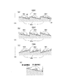
ブレーズ型構造とは、図5(a)、(b)に示されるように、光路差付与構造を有する光学素子の光軸を含む断面形状が、鋸歯状の形状ということである。尚、図5の例においては、上方が光源側、下方が光ディスク側であって、母非球面としての平面に光路差付与構造が形成されているものとする。ブレーズ型構造において、1つのブレーズ単位の光軸垂直方向の長さをピッチPという。(図5(a)、(b)参照)また、ブレーズの光軸に平行方向の段差の長さを段差量Bという。(図5(a)参照)このような単一のブレーズ型構造では互いに向かい合う周壁は存在しない。
また、階段型構造とは、図5(c)、(d)に示されるように、光路差付与構造を有する光学素子の光軸を含む断面形状が、小階段状のもの(階段単位と称する)を複数有するということである。尚、本明細書中、「Vレベル」とは、階段型構造の1つの階段単位において光軸垂直方向に対応する(向いた)輪帯状の面(以下、テラス面と称することもある)が、段差によって区分けされV個の輪帯面毎に分割されていることをいい、特に3レベル以上の階段型構造は、小さい段差と大きい段差を有することになる。例えば、図5(c)に示す光路差付与構造を、5レベルの階段型構造といい、図5(d)に示す光路差付与構造を、2レベルの階段型構造(バイナリ構造ともいう)という。
尚、光路差付与構造は、ある単位形状が周期的に繰り返されている構造であることが好ましい。 ここでいう「単位形状が周期的に繰り返されている」とは、同一の形状が同一の周期で繰り返されている形状は当然含む。さらに、周期の1単位となる単位形状が、規則性を持って、周期が徐々に長くなったり、徐々に短くなったりする形状も、「単位形状が周期的に繰り返されている」ものに含まれているとする。
また、第1光路差付与構造及び第2光路差付与構造を設ける場合は、それぞれ対物レンズの異なる光学面に設けてもよいが、同一の光学面に設けることが好ましい。更に、第3光路差付与構造を設ける場合も、第1光路差付与構造及び第2光路差付与構造と同じ光学面に設けることが好ましい。同一の光学面に設けることにより、製造時の偏芯誤差を少なくすることが可能となるため好ましい。また、第1光路差付与構造、第2光路差付与構造及び第3光路差付与構造は、対物レンズの光ディスク側の面よりも、対物レンズの光源側の面に設けられることが好ましい。別の言い方では、第1光路差付与構造、第2光路差付与構造及び第3光路差付与構造は、対物レンズの曲率半径の絶対値が小さい方の光学面に設けることが好ましい。尚、第1基礎構造と第2基礎構造を重畳せずに、それぞれ異なる光学面に設けることも考えられる。第3基礎構造と第4基礎構造も、同様に重畳せずにそれぞれ異なる光学面に設けることも考えられる。
光路差付与構造は、複数の基礎構造(例えば図6(d)の第1基礎構造と第2基礎構造)を重ね合わせた構造としても良い。
光路差付与構造の重畳例をいくつか図6(a)、(b)、(c)として示す。これらは2種類のブレーズ型構造を重畳した例である。尚、図6は、便宜上、第1光路差付与構造ODS1が平板状に設けられたものとして示されているが、単玉非球面の凸レンズ上に設けられていてもよい。第2基礎構造を通過した第1光束の2次の回折光量を他のいかなる次数の回折光量よりも大きくし、第2基礎構造を通過した第2光束の1次の回折光量を他のいかなる次数の回折光量よりも大きくし、第2基礎構造を通過した第3光束の1次の回折光量を他のいかなる次数の回折光量よりも大きくする(「2/1/1」)回折構造である第2基礎構造BS2に、第1基礎構造を通過した第1光束の1次の回折光量を他のいかなる次数の回折光量よりも大きくし、第1基礎構造を通過した第2光束の1次の回折光量を他のいかなる次数の回折光量よりも大きくし、第1基礎構造を通過した第3光束の1次の回折光量を他のいかなる次数の回折光量よりも大きくする(「1/1/1」)回折構造である第1基礎構造BS1が重ねあわされた例である。図6(a)においては、第2基礎構造BS2の段差は光軸OAの方向を向いており、第1基礎構造BS1の段差は光軸OAとは逆の方向を向いている。更に、第2基礎構造BS2の全ての段差の位置と、第1基礎構造BS1の段差の位置が合っていることがわかる。次に、図6(b)においては、第2基礎構造BS2の段差は光軸OAの方向を向いており、第1基礎構造BS1の段差も光軸OAの方向を向いている。更に、第2基礎構造BS2の全ての段差の位置と、第1基礎構造BS1の段差の位置が合っていることがわかる。次に、図6(c)においては、第1基礎構造BS1の段差は光軸OAと逆の方向を向いており、第2基礎構造BS2の段差も光軸OAと逆の方向を向いている。更に、第2基礎構造BS2の全ての段差の位置と、第1基礎構造BS1の段差の位置が合っていることがわかる。
光路差付与構造の種々の例を述べてきたが、本明細書において、「向かい合う周壁を備えた輪帯溝を有する光路差付与構造」というときは、特に図5(c)、(d)、図6(a)に示す構造をいう。
BDに対して情報を再生/記録するために必要な対物レンズの像側開口数をNA1とし、DVDに対して情報を再生/記録するために必要な対物レンズの像側開口数をNA2(NA1>NA2)とし、CDに対して情報を再生/記録するために必要な対物レンズの像側開口数をNA3(NA2>NA3)とする。NA1は、0.75以上、0.9以下であることが好ましく、より好ましくは、0.8以上、0.9以下である。特にNA1は0.85であることが好ましい。NA2は、0.55以上、0.7以下であることが好ましい。特にNA2は0.60又は0.65であることが好ましい。また、NA3は、0.4以上、0.55以下であることが好ましい。特にNA3は0.45又は0.53であることが好ましい。
対物レンズの中央領域と中間領域の境界は、第3光束の使用時において、0.9・NA3以上、1.2・NA3以下(より好ましくは、0.95・NA3以上、1.15・NA3以下)の範囲に相当する部分に形成されていることが好ましい。より好ましくは、対物レンズの中央領域と中間領域の境界が、NA3に相当する部分に形成されていることである。また、対物レンズの中間領域と周辺領域の境界は、第2光束の使用時において、0.9・NA2以上、1.2・NA2以下(より好ましくは、0.95・NA2以上、1.15・NA2以下)の範囲に相当する部分に形成されていることが好ましい。より好ましくは、対物レンズの中間領域と周辺領域の境界が、NA2に相当する部分に形成されていることである。
対物レンズを通過した第3光束をCDの情報記録面上に集光する場合に、球面収差が少なくとも1箇所の不連続部を有することが好ましい。その場合、不連続部は、第3光束の使用時において、0.9・NA3以上、1.2・NA3以下(より好ましくは、0.95・NA3以上、1.15・NA3以下)の範囲に存在することが好ましい。
また、本発明は、薄いスリム型の光ピックアップ装置に用いられる対物レンズにおいて特に好適である。スリム型の光ピックアップ装置に用いられる対物レンズは、必然的に小径になるため、輪帯のピッチも小さくなり、加工が困難となる。そのため、加工しやすく、それでいて、光利用効率のロスが少ない本発明の効果がより顕著となるのである。
尚、スリム型の光ピックアップ装置に用いられる対物レンズは、フランジ及び光学面すべて含めた対物レンズ全体の光軸直交方向の直径が、1.45mm以上、4.05mm以下であることが好ましい。より好ましくは、2.95mm以上、4.05mm以下である。また、光路差付与構造の光軸直交方向のピッチの最小値が、2.5μm以上、10μm以下であることが好ましい。また、ピッチの最大値が、110μm以下であることが好ましい。更に、対物レンズ全体における光路差付与構造の全輪帯数が、150以上、250以下であることが好ましい。
本発明で用いる工具は、第1の縁部と該第1の縁部に交差する方向に延在する第2の縁部とから少なくとも一部が輪郭づけられるすくい面を備えている。取り付けた状態で、第1の縁部が、第2の縁部よりも金型の素材の回転軸線より遠い位置になる。第1の縁部と第2の縁部とは工具軸線を境界として直接接続していても良いし、工具軸線をまたぐ第3の縁部を介して接続していても良い。第1の縁部と第2の縁部は、それぞれストレート形状であると好ましいが、一部が円弧状であっても良い。
本発明によれば、例えばBD/DVD/CDの3種類の光ディスク互換用の対物レンズ等の光学素子を成形する金型であって、光学素子の効率低下を極力抑えることができる金型の加工方法、加工された金型、及び金型から転写された光学素子を提供することができる。
以下、本発明の実施の形態を、図面を参照して説明する。先ず、codeV等の光学設計ソフトウェアを用いて、BD/DVD/CD互換対物レンズの設計を行う。そして、当該設計結果に基づいて、金型の加工を行っていく。図7(a)は、本実施の形態にかかる金型の加工方法で用いるダイヤモンド工具の切れ刃を示す斜視図であり、図7(b)は、すくい面3aの先端部形状を示す拡大図である。ダイヤモンド工具の切れ刃3は、図に示すようにシャンクSに対してろう付けされており、切削されるべき型の回転方向に正対するすくい面3aを有している。かかるすくい面3aの先端部は、第1の縁部である縁部3b及び第2の縁部である縁部3cと、縁部3bの端部Aと縁部3cの端部Bとを結ぶ第3の縁部である円弧部3dとから輪郭づけられている。
すくい面3aの円弧部3dの半径rを0.1~0.5μm(好ましくは0.1~0.3、μm)とすることで、刃先を鋭利にして高精度な微細形状を切削できる。第1の縁部3bと、第2の縁部3cとのはさみ角(頂角)は20~30°(好ましくは29°以下)とするのがよい。尚、第1の縁部3bと第2の縁部3cの二等分線を、工具3の軸線BXとする。
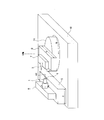
図8は、型の加工に用いるXZB軸超精密旋盤の斜視図である。図9は、ダイヤモンド工具を用いて金型を切削する際の拡大断面図である。図8において、定盤10に対して、Z軸方向に移動自在なZ軸ステージ5上には、回転駆動機構9が設けられ、回転駆動機構9は、切削すべき金型素材1を、回転軸線AX回りで回転駆動するようになっている。一方、定盤10に対して、B軸回りに回転可能なB軸ステージ11が設けられ、B軸ステージ11上にはX方向に移動自在なX軸ステージ6が設けられ、X軸ステージ6上には工具取付部7が設けられて、ダイヤモンド工具3を把持している。B軸ステージ11により、ダイヤモンド工具3の工具軸線を傾けた状態に維持し、回転駆動機構9により金型素材1を回転させながら、Z軸ステージ5,X軸ステージ6によりダイヤモンド工具3を金型素材1に対して相対的に移動させることで、光学転写面の加工を行えるようになっている。
本実施の形態では、金型素材1は鉄系の母材を使用し、切削面に対して要求形状を粗取りした後、加工層として無電解ニッケルメッキを約50μmの厚さで施している。
金型素材1の光学面(被加工面)1aに要求される形状は、BD/DVD/CD互換用プラスチック対物レンズの回折光学面形状である。
金型素材1を例えば1000回転毎分で回転させると共に、X軸ステージ6及びZ軸ステージ5をプログラム制御により、ダイヤモンド工具3の先端部が、図9の矢印で示すように、金型素材1の外周側から中心部に向かって、毎分0.1mmの移動速度で並進移動して、所望の回折光学面形状が得られるように移動させる。
ここで、第1の加工態様によれば、ダイヤモンド工具3の頂角の2等分線BX(図7(b)参照)を、金型素材1の回転軸線AXに対して傾けたまま、外周から中央まで切削加工を行う。この時、頂角の2等分線BXの回転軸線に対する傾け角度は、頂角の約半分であることが好ましい。この場合、8°~18°である。かかる場合、図9において、第1の縁部3b(但し、傾け角によっては第3の縁部3dにて切削する場合もあるが、この場合、工具軸線を挟んで回転軸線から遠い側で切削する縁部を第1の縁部と定義する)により、輪帯状の凸部1dにおける光軸に近い側の周面(第1の周面)(凹部においては光軸から離れた側の周面となる)1bを回転軸線AXに対して平行に形成できる。つまり、かかる加工により切削された金型を用いて対物レンズを成形すると、輪帯凸部の光軸から遠い側の周壁(図1の外側壁OWに相当)が光軸と平行になる対物レンズを形成できる。一方、第2の縁部3cにより、輪帯状の凸部1dにおける光軸から遠い側の周面(第2の周面)(凹部においては光軸に近い側の周面となる)1cを形成できる。つまり、かかる加工により切削された金型を用いて対物レンズを形成すると、輪帯凸部の光軸から近い側の周壁(図1の内側壁IWに相当)が光軸に対して輪帯凸部の先端に向かうにつれて光軸から離れるように傾いている対物レンズを形成できる。尚、第1の縁部3bを回転軸線AXとを、厳密に平行とする必要はない。第1の縁部3bが回転軸線AXと平行になる位置よりも、すくい面の先端が回転軸線AXに近づく方向に傾けなければ、ダイヤモンド工具3のZ方向への相対移動によって、光軸に近い側の周面1bを回転軸線AXに対して平行に形成できるからである。
更に、第2の加工態様によれば、金型素材1の加工面1aの外周から中間部までは、ダイヤモンド工具3の頂角の2等分線BXを、金型素材1の回転軸線AXに平行においた状態で切削加工を行い、次いで、図8におけるB軸を中心にダイヤモンド工具3を回転させ、中間部から中央までは、ダイヤモンド工具3の頂角の2等分線BXを、金型素材1の回転軸線AXに対して傾けた状態に角度を変更して切削加工を行うこともできる。かかる場合、第1の縁部3bにより、中間部から中央までの範囲で、輪帯状の凸部1dにおける光軸に近い側の周面1bを回転軸線AXに対して平行に形成できる。つまり、かかる加工により切削された金型を用いて対物レンズを成形すると、中間部から中央までの範囲で輪帯溝の光軸に近い側の周壁が光軸と平行になる対物レンズを形成できる。
図10,11は、加工したい金型の一部にかかる拡大断面形状を示しており、金型の形状をハッチングで示す。
本発明者らは、ダイヤモンド工具3の頂角の2等分線BXを、金型素材1の回転軸線AXに対して傾けない比較例の金型と、ダイヤモンド工具3の頂角の2等分線BXを、金型素材1の回転軸線AXに対して傾けた実施例の金型とをそれぞれ製造し、両金型にて互換用の回折構造を有する対物レンズを成形した。比較例の金型から成形した対物レンズの回折効率を測定したところ、BD使用時の回折効率:74.1%、DVD使用時の回折効率:56.4%、CD使用時の回折効率:52.1%であった。一方、実施例の金型から成形した対物レンズの回折効率を測定したところ、BD使用時の回折効率:76.2%(+2.1%)、DVD使用時の回折効率:62.8%(+6.4%)、CD使用時の回折効率:58.3%(+6.2%)であり、いずれの波長域でも回折効率が増大し、本発明の効果が確認された。
本発明は、明細書に記載の実施例に限定されるものではなく、他の実施例・変形例を含むことは、本明細書に記載された実施例や思想から本分野の当業者にとって明らかである。明細書の記載及び実施例は、あくまでも例証を目的としており、本発明の範囲は後述するクレームによって示されている。例えば光学素子とは対物レンズに限られない。
1 金型素材
1a 加工面
1b 周面
3 ダイヤモンド工具
3a すくい面
3b 第1の縁部
3c 第2の縁部
3d 円弧部(第3の縁部)
4 光学面
5 Z軸ステージ
6 X軸ステージ
7 工具取付部
9 回転駆動機構
10 定盤
11 B軸ステージ
A 端部
AX 回転軸線
B 端部
BX 2等分線
1a 加工面
1b 周面
3 ダイヤモンド工具
3a すくい面
3b 第1の縁部
3c 第2の縁部
3d 円弧部(第3の縁部)
4 光学面
5 Z軸ステージ
6 X軸ステージ
7 工具取付部
9 回転駆動機構
10 定盤
11 B軸ステージ
A 端部
AX 回転軸線
B 端部
BX 2等分線
Claims (14)
- 光学素子を成形する金型の素材を、第1の縁部と該第1の縁部に交差する方向に延在する第2の縁部とから少なくとも一部が輪郭づけられるすくい面を備えた工具にて切削する金型の加工方法において、
前記第1の縁部が、前記第2の縁部よりも金型の素材の回転軸線より遠い位置になり、且つ前記すくい面の先端が回転軸線より離れるように、前記工具の軸線を前記回転軸線に対して傾けてセットした前記工具により、金型の素材を回転させながら切削することにより、前記第1の縁部により切削された第1の周面と、前記第2の縁部により切削された第2の周面とを有する凹状の輪帯構造を少なくとも一部形成することを特徴とする金型の加工方法。 - 前記素材の被加工部における外周から中央まで、前記工具の軸線を前記回転軸線に対して傾けてセットした状態で切削することを特徴とする請求項1に記載の金型の加工方法。
- 前記工具の軸線の前記回転軸線に対する傾き角を、前記素材の被加工部の切削途中で変更することを特徴とする請求項1に記載の金型の加工方法。
- 前記素材の被加工部における外周から中間部まで、前記工具の軸線を前記回転軸線に平行にセットした状態で切削し、前記中間部から中央まで、前記工具の軸線を前記回転軸線に対して傾けてセットした状態で切削することを特徴とする請求項3に記載の金型の加工方法。
- 少なくとも一部の凹状の輪帯構造の周壁において、少なくとも前記輪帯構造の光軸から遠い側の周壁は、光軸に対して平行であることを特徴とする請求項1乃至4のいずれか1項に記載の金型の加工方法。
- 前記凹状の輪帯構造の周壁において、少なくとも前記輪帯構造の光軸に近い側の周壁は、光軸に対して傾いていることを特徴とする請求項5に記載の金型の加工方法。
- 前記工具のすくい面は、前記第1の縁部端部と前記第2の縁部端部とを結ぶ円弧状の第3の縁部を有し、前記第3の縁部の半径は、0.1~0.5μmであることを特徴とする請求項1乃至6のいずれか1項に記載の金型の加工方法。
- 前記工具の軸線の前記回転軸線に対する傾け角が、前記第1の縁部と前記第2の縁部とがなす頂角の約半分であることを特徴とする請求項1乃至7のいずれか1項に記載の金型の加工方法。
- 前記第1の縁部と前記第2の縁部とがなす頂角は、20~30°であることを特徴とする請求項1乃至8のいずれか1項に記載の金型の加工方法。
- 前記工具の軸線の前記回転軸線に対する傾け角が、8~18°であることを特徴とする請求項9に記載の金型加工方法。
- 請求項1乃至10のいずれか1項に記載の加工方法により加工されたことを特徴とする金型。
- 第1波長λ1(390nm≦λ1≦415nm)の第1光束を射出する第1光源と、第2波長λ2(630nm≦λ2≦670nm)の第2光束を射出する第2光源と、第3波長λ3(760nm≦λ3≦820nm)の第3光束を射出する第3光源とを有し、前記第1光束を用いて厚さがt1の保護基板を有するBDの情報の記録及び/又は再生を行い、前記第2光束を用いて厚さがt2(t1<t2)の保護基板を有するDVDの情報の記録及び/又は再生を行い、前記第3光束を用いて厚さがt3(t2<t3)の保護基板を有するCDの情報の記録及び/又は再生を行う光ピックアップ装置において用いられる光学素子であって、
前記光学素子の少なくとも一つの光学面は、中央領域と、中央領域の周りの中間領域と、中間領域の周りの周辺領域とを少なくとも有し、
前記光学素子は、前記中央領域を通過する前記第1光束を、BDの情報記録面上に情報の記録及び/又は再生ができるように集光し、前記中央領域を通過する前記第2光束を、DVDの情報記録面上に情報の記録及び/又は再生ができるように集光し、前記中央領域を通過する前記第3光束を、CDの情報記録面上に情報の記録及び/又は再生ができるように集光し、
前記中間領域を通過する前記第1光束を、BDの情報記録面上に情報の記録及び/又は再生ができるように集光し、前記中間領域を通過する前記第2光束を、DVDの情報記録面上に情報の記録及び/又は再生ができるように集光し、前記中間領域を通過する前記第3光束を、CDの情報記録面上に情報の記録及び/又は再生ができるように集光せず、
前記周辺領域を通過する前記第1光束を、BDの情報記録面上に情報の記録及び/又は再生ができるように集光し、前記周辺領域を通過する前記第2光束を、DVDの情報記録面上に情報の記録及び/又は再生ができるように集光せず、前記周辺領域を通過する前記第3光束を、CDの情報記録面上に情報の記録及び/又は再生ができるように集光せず、
前記中央領域は、第1光路差付与構造を備え、
前記第1光路差付与構造は、ブレーズ型構造を有する第1基礎構造とブレーズ型構造を有する第2基礎構造を互いに逆向きに重ね合わせた構造であり、
前記第1基礎構造の段差は光軸とは逆の方向を向いており、前記第2基礎構造の段差は光軸の方向を向いており、
前記第1基礎構造を通過した前記第1光束の1次の回折光量は他のいかなる次数の回折光量よりも大きくなり、前記第1基礎構造を通過した前記第2光束の1次の回折光量は他のいかなる次数の回折光量よりも大きくなり、前記第1基礎構造を通過した前記第3光束の1次の回折光量は他のいかなる次数の回折光量よりも大きくなり、
前記第2基礎構造を通過した前記第1光束の2次の回折光量は他のいかなる次数の回折光量よりも大きくなり、前記第2基礎構造を通過した前記第2光束の1次の回折光量は他のいかなる次数の回折光量よりも大きくなり、前記第1基礎構造を通過した前記第3光束の1次の回折光量は他のいかなる次数の回折光量よりも大きくなり、
前記第1光路差付与構造は、略光軸方向に延在し互いに向かい合う周壁を備えた輪帯凸部を有し、少なくとも前記輪帯凸部の光軸から遠い側の周壁は、光軸に対して平行であり、前記輪帯凸部の光軸に近い側の周壁は、光軸に対して前記輪帯凸部の先端に向かうにつれて光軸から離れるように傾いていることを特徴とする光学素子。 - 前記輪帯凸部は光路差付与構造であることを特徴とする請求項12に記載の光学素子。
- 前記光学素子は対物レンズであることを特徴とする請求項12又は13に記載の光学素子。
Priority Applications (3)
| Application Number | Priority Date | Filing Date | Title |
|---|---|---|---|
| CN201280016313.5A CN103459114B (zh) | 2011-03-31 | 2012-03-28 | 模具的加工方法、模具以及光拾取装置用的光学元件 |
| PH1/2013/501989A PH12013501989A1 (en) | 2011-03-31 | 2012-03-28 | Method for machining mold, mold, and optical element for optical pickup device |
| JP2012540200A JPWO2012133531A1 (ja) | 2011-03-31 | 2012-03-28 | 金型の加工方法 |
Applications Claiming Priority (2)
| Application Number | Priority Date | Filing Date | Title |
|---|---|---|---|
| JP2011077110 | 2011-03-31 | ||
| JP2011-077110 | 2011-03-31 |
Publications (1)
| Publication Number | Publication Date |
|---|---|
| WO2012133531A1 true WO2012133531A1 (ja) | 2012-10-04 |
Family
ID=46931240
Family Applications (1)
| Application Number | Title | Priority Date | Filing Date |
|---|---|---|---|
| PCT/JP2012/058143 Ceased WO2012133531A1 (ja) | 2011-03-31 | 2012-03-28 | 金型の加工方法、金型及び光ピックアップ装置用の光学素子 |
Country Status (4)
| Country | Link |
|---|---|
| JP (2) | JPWO2012133531A1 (ja) |
| CN (1) | CN103459114B (ja) |
| PH (1) | PH12013501989A1 (ja) |
| WO (1) | WO2012133531A1 (ja) |
Families Citing this family (1)
| Publication number | Priority date | Publication date | Assignee | Title |
|---|---|---|---|---|
| HUE038956T2 (hu) * | 2015-10-02 | 2018-12-28 | Rayner Intraocular Lenses Ltd | Multifokális lencse |
Citations (4)
| Publication number | Priority date | Publication date | Assignee | Title |
|---|---|---|---|---|
| JPS62102901A (ja) * | 1985-10-28 | 1987-05-13 | Toshiba Corp | 光学部品製作方法 |
| JPH1110401A (ja) * | 1997-04-21 | 1999-01-19 | Asahi Optical Co Ltd | 輪帯レンズ成形用金型の加工方法及びそのバイト |
| JP2001129702A (ja) * | 1999-11-05 | 2001-05-15 | Canon Inc | 成形用金型部材の加工方法、成形用金型部材の加工装置、及び、表面に微細光学機能形状を形成した光学部品、並びに、光学素子の保持部材 |
| JP2003062707A (ja) * | 2001-08-22 | 2003-03-05 | Konica Corp | ダイヤモンド工具、加工方法、光学素子成形用金型及び合成樹脂製光学素子 |
Family Cites Families (4)
| Publication number | Priority date | Publication date | Assignee | Title |
|---|---|---|---|---|
| JP3963750B2 (ja) * | 2002-03-25 | 2007-08-22 | 日本電産サンキョー株式会社 | 曲面切削加工方法 |
| JP3880474B2 (ja) * | 2002-07-11 | 2007-02-14 | キヤノン株式会社 | 金型の加工方法 |
| JP2005096064A (ja) * | 2003-09-02 | 2005-04-14 | Japan Science & Technology Agency | 軸対称回折曲面の切削加工方法及びそれによって作製される物品 |
| WO2009128313A1 (ja) * | 2008-04-18 | 2009-10-22 | コニカミノルタオプト株式会社 | 光学素子用金型の加工方法、成形用金型、及び光学素子 |
-
2012
- 2012-03-28 WO PCT/JP2012/058143 patent/WO2012133531A1/ja not_active Ceased
- 2012-03-28 JP JP2012540200A patent/JPWO2012133531A1/ja active Pending
- 2012-03-28 PH PH1/2013/501989A patent/PH12013501989A1/en unknown
- 2012-03-28 CN CN201280016313.5A patent/CN103459114B/zh not_active Expired - Fee Related
- 2012-09-12 JP JP2012200134A patent/JP5310918B2/ja active Active
Patent Citations (4)
| Publication number | Priority date | Publication date | Assignee | Title |
|---|---|---|---|---|
| JPS62102901A (ja) * | 1985-10-28 | 1987-05-13 | Toshiba Corp | 光学部品製作方法 |
| JPH1110401A (ja) * | 1997-04-21 | 1999-01-19 | Asahi Optical Co Ltd | 輪帯レンズ成形用金型の加工方法及びそのバイト |
| JP2001129702A (ja) * | 1999-11-05 | 2001-05-15 | Canon Inc | 成形用金型部材の加工方法、成形用金型部材の加工装置、及び、表面に微細光学機能形状を形成した光学部品、並びに、光学素子の保持部材 |
| JP2003062707A (ja) * | 2001-08-22 | 2003-03-05 | Konica Corp | ダイヤモンド工具、加工方法、光学素子成形用金型及び合成樹脂製光学素子 |
Also Published As
| Publication number | Publication date |
|---|---|
| CN103459114B (zh) | 2016-09-28 |
| PH12013501989A1 (en) | 2013-11-25 |
| CN103459114A (zh) | 2013-12-18 |
| JP2013049272A (ja) | 2013-03-14 |
| JP5310918B2 (ja) | 2013-10-09 |
| JPWO2012133531A1 (ja) | 2014-07-28 |
Similar Documents
| Publication | Publication Date | Title |
|---|---|---|
| JP5370539B2 (ja) | 対物レンズ、光ピックアップ装置及び光情報記録再生装置 | |
| JP2011096350A (ja) | 光ピックアップ装置用の対物レンズ、光ピックアップ装置及び光情報記録再生装置 | |
| JP5740797B2 (ja) | 対物レンズ及び光ピックアップ装置 | |
| JP5310918B2 (ja) | 光ピックアップ装置用の光学素子 | |
| JP5602833B2 (ja) | 対物レンズ、光学ヘッド及び光ディスク装置 | |
| JP2007334952A (ja) | 光情報記録再生装置用対物レンズ | |
| JP6065347B2 (ja) | 対物レンズ及び光ピックアップ装置 | |
| JP2005310346A (ja) | 光学素子及び光ピックアップ装置 | |
| WO2011136096A1 (ja) | 光ピックアップ装置用の対物レンズ、光ピックアップ装置及び光情報記録再生装置 | |
| JPWO2011132691A1 (ja) | 光ピックアップ装置用の対物レンズ、光ピックアップ装置及び光情報記録再生装置 | |
| JP2010055732A (ja) | 対物光学素子及び光ピックアップ装置 | |
| JP5963120B2 (ja) | 対物レンズ、光ピックアップ装置及び光情報記録再生装置 | |
| WO2013005672A1 (ja) | 光ピックアップ装置 | |
| JP5229657B2 (ja) | 光ピックアップ装置用の対物レンズ、光ピックアップ装置及び光情報記録再生装置 | |
| JP2013206515A (ja) | 光ピックアップ装置用の対物レンズ、光ピックアップ装置及び光情報記録再生装置 | |
| JPWO2013168692A1 (ja) | 対物レンズ及び光ピックアップ装置 | |
| JP2013206516A (ja) | 光ピックアップ装置用の対物レンズ、光ピックアップ装置及び光情報記録再生装置 | |
| JP2013157049A (ja) | 光ピックアップ装置用の対物レンズ、光ピックアップ装置及び光情報記録再生装置 | |
| WO2012090852A1 (ja) | 光ピックアップ装置用の対物レンズ、光ピックアップ装置及び光情報記録再生装置 | |
| JP2009283134A (ja) | 光学素子及び光ピックアップ装置 | |
| JP2014164791A (ja) | 光ピックアップ装置用の対物レンズ、光ピックアップ装置及び光情報記録再生装置 | |
| JP2013051002A (ja) | 光ピックアップ装置用の対物レンズ | |
| WO2013084558A1 (ja) | 光ピックアップ装置用の対物レンズ、光ピックアップ装置及び光情報記録再生装置 |
Legal Events
| Date | Code | Title | Description |
|---|---|---|---|
| ENP | Entry into the national phase |
Ref document number: 2012540200 Country of ref document: JP Kind code of ref document: A |
|
| 121 | Ep: the epo has been informed by wipo that ep was designated in this application |
Ref document number: 12765887 Country of ref document: EP Kind code of ref document: A1 |
|
| NENP | Non-entry into the national phase |
Ref country code: DE |
|
| 122 | Ep: pct application non-entry in european phase |
Ref document number: 12765887 Country of ref document: EP Kind code of ref document: A1 |