WO2012133460A1 - シールドコネクタ - Google Patents
シールドコネクタ Download PDFInfo
- Publication number
- WO2012133460A1 WO2012133460A1 PCT/JP2012/058012 JP2012058012W WO2012133460A1 WO 2012133460 A1 WO2012133460 A1 WO 2012133460A1 JP 2012058012 W JP2012058012 W JP 2012058012W WO 2012133460 A1 WO2012133460 A1 WO 2012133460A1
- Authority
- WO
- WIPO (PCT)
- Prior art keywords
- shield
- connector
- cable
- shield case
- shell
- Prior art date
Links
Images


Classifications
-
- H—ELECTRICITY
- H01—ELECTRIC ELEMENTS
- H01R—ELECTRICALLY-CONDUCTIVE CONNECTIONS; STRUCTURAL ASSOCIATIONS OF A PLURALITY OF MUTUALLY-INSULATED ELECTRICAL CONNECTING ELEMENTS; COUPLING DEVICES; CURRENT COLLECTORS
- H01R13/00—Details of coupling devices of the kinds covered by groups H01R12/70 or H01R24/00 - H01R33/00
- H01R13/648—Protective earth or shield arrangements on coupling devices, e.g. anti-static shielding
- H01R13/658—High frequency shielding arrangements, e.g. against EMI [Electro-Magnetic Interference] or EMP [Electro-Magnetic Pulse]
- H01R13/6591—Specific features or arrangements of connection of shield to conductive members
-
- H—ELECTRICITY
- H01—ELECTRIC ELEMENTS
- H01R—ELECTRICALLY-CONDUCTIVE CONNECTIONS; STRUCTURAL ASSOCIATIONS OF A PLURALITY OF MUTUALLY-INSULATED ELECTRICAL CONNECTING ELEMENTS; COUPLING DEVICES; CURRENT COLLECTORS
- H01R13/00—Details of coupling devices of the kinds covered by groups H01R12/70 or H01R24/00 - H01R33/00
- H01R13/648—Protective earth or shield arrangements on coupling devices, e.g. anti-static shielding
- H01R13/658—High frequency shielding arrangements, e.g. against EMI [Electro-Magnetic Interference] or EMP [Electro-Magnetic Pulse]
- H01R13/6581—Shield structure
-
- H—ELECTRICITY
- H01—ELECTRIC ELEMENTS
- H01R—ELECTRICALLY-CONDUCTIVE CONNECTIONS; STRUCTURAL ASSOCIATIONS OF A PLURALITY OF MUTUALLY-INSULATED ELECTRICAL CONNECTING ELEMENTS; COUPLING DEVICES; CURRENT COLLECTORS
- H01R13/00—Details of coupling devices of the kinds covered by groups H01R12/70 or H01R24/00 - H01R33/00
- H01R13/73—Means for mounting coupling parts to apparatus or structures, e.g. to a wall
- H01R13/74—Means for mounting coupling parts in openings of a panel
- H01R13/748—Means for mounting coupling parts in openings of a panel using one or more screws
-
- H—ELECTRICITY
- H01—ELECTRIC ELEMENTS
- H01R—ELECTRICALLY-CONDUCTIVE CONNECTIONS; STRUCTURAL ASSOCIATIONS OF A PLURALITY OF MUTUALLY-INSULATED ELECTRICAL CONNECTING ELEMENTS; COUPLING DEVICES; CURRENT COLLECTORS
- H01R2201/00—Connectors or connections adapted for particular applications
- H01R2201/26—Connectors or connections adapted for particular applications for vehicles
Definitions
- the present invention relates to a shield connector for connecting an external cable to a circuit in a shield case of a device.
- FIG. 8 shows a conventional example of a shield connector.
- the shield connector 100 is disclosed in Patent Document 1 below.
- the shield connector 100 is a connector for connecting the external cable 110 to a circuit in a shield case 103 of a device mounted on a vehicle or the like.
- the shield connector 100 includes a cable-side connection terminal 120 that is crimped to the tip of an external cable 110, a resin housing 130 that accommodates and holds the cable-side connection terminal 120, and a shield case 103 that holds the resin housing 130. And a seal shell 140 that is screwed to each other and a packing 150 that seals between the shield connector 100 and the shield case 103.
- the cable side connection terminal 120 includes a tongue-shaped terminal portion 121 at one end and a wire crimping portion 122 at the other end.
- the tongue-shaped terminal portion 121 is a portion connected to the tongue-shaped terminal 104 of the circuit in the shield case 103 via screw members 105 and 106.
- the wire crimping part 122 is a part that is crimped to the end of the external cable 110.
- the resin housing 130 is integrally formed in a form in which the cable side connection terminal 120 is accommodated by molding.
- the outer shape of the resin housing 130 is a columnar shape that can be inserted into the connector insertion hole 107 formed through the shield case 103.
- a packing mounting groove 131 for mounting the packing 150 is formed in an annular shape that goes around the outer periphery.
- the shield shell 140 extends in a bowl shape from the cylindrical shell main body 141 that holds the base end portion 130 a of the resin housing 130 that houses the end of the external cable 110, and the end of the shell main body 141 on the shield case 103 side. And a case fixing flange portion 142 provided.
- the case fixing flange 142 is brought into face contact with the outer surface of the shield case 103 and is screwed to the shield case 103 with a bolt 108.
- the shield connector 100 is fixed to the shield case 103 by screwing the case fixing flange portion 142 to the shield case 103.
- the packing 150 is a ring-shaped packing that is mounted in the packing mounting groove 131 of the resin housing 130.
- the packing 150 closes a gap between the inner peripheral surface of the connector insertion hole 107 and the outer peripheral surface of the resin housing 130 and seals between the shield connector 100 and the shield case 103.
- the ring-shaped packing 150 provided on the outer periphery of the resin housing 130 that is inserted through the connector insertion hole 107 is brought into close contact with the inner peripheral surface of the connector insertion hole 107.
- the shield connector 100 and the shield case 103 are sealed. Therefore, when the external cable 110 is repeatedly attached to and detached from the shield case 103, the packing 150 is easily damaged by sliding with the connector insertion hole 107, and the sealing performance at the attachment portion to the shield case 103 may be deteriorated.
- the mounting dimensions on the shield case 103 such as a change in the arrangement of the screw holes 109 on the shield case 103 to which the bolts 108 are screwed or a change in the shape or dimensions of the connector insertion hole 107 are changed.
- the change is supported.
- the mounting dimensions on the shield case 103 side are changed, it is necessary to change the design of a large number of components, and there is a problem that a great deal of labor is required for product development corresponding to the change in the mounting dimensions on the shield case side. there were.
- an object of the present invention is to solve the above-mentioned problems, and even if the external cable is repeatedly attached to and detached from the shield case, the sealing performance at the attachment portion to the shield case does not deteriorate, and the shield It is an object of the present invention to provide a shielded connector that can facilitate product development corresponding to a change in mounting dimensions on the case side.
- a shield connector for connecting an external cable to a circuit in a shield case of a device A device-side connector that is fixed to the shield case, and a cable-side connector that is attached to an end of the external cable and is connected to the device-side connector;
- the device-side connector is One end is connected to the circuit in the shield case and the other end is fitted and connected to the connection terminal on the cable side connector side, Housing and holding the device-side connection terminal and fitting and connecting the cable-side connector, and a device-side resin housing;
- the device side shield shell having a case fixing flange portion that holds the device side resin housing and is screwed to the outer surface of the shield case in a surface contact state;
- a first packing that is pressed against the outer surface of the shield case by screwing the case fixing flange portion to the shield case and seals between the device-side connector and the shield case;
- the device-side shield shell includes a mating shell fixing portion that couples the device-side shield shell and the cable-side
- the device-side shield shell is formed in a thick wall shape projecting outward of the shield case from the projecting height of a screw member that fastens the case fixing flange portion to the shield case.
- a thick part that functions as a hood part that accommodates the fitting part of the cable side connector is provided,
- the shield connector is composed of a device-side connector fixed to the shield case, and a cable-side connector that is attached to the end of the external cable and is fitted and connected to the device-side connector. ing. Therefore, attachment / detachment of the external cable to / from the shield case is realized by attaching / detaching the cable-side connector to / from the device-side connector.
- the device-side connector when the external cable is attached to or detached from the shield case, the device-side connector may remain fixed to the shield case, and even if the external cable is repeatedly attached to and detached from the shield case, the device-side connector may remain between the device-side connector and the shield case.
- the first packing that seals is not affected at all.
- the sealing between the shield case and the device side connector is performed by a first packing sandwiched between the case fixing flange portion of the shield shell and the outer surface of the shield case, and the device side resin housing Need only be loosely fitted into the connector insertion hole on the shield case, and the dimensional accuracy of the outer shape of the device-side resin housing does not affect the sealing performance at the attachment portion to the shield case.
- the change can be dealt with by changing the design of only the shield shell that is attached to the shield case.
- the mating dimensions of can be kept as they were in the past.
- the device-side resin housing since the thick portion provided in the shield shell also serves as the hood portion that houses the tip portion of the cable-side connector, the device-side resin housing has the tip portion of the cable-side connector. It is not necessary to form a hood to be accommodated, and the structure of the device-side resin housing can be simplified.
- the mating shell fixing part is equipped in the thick part, it is possible to secure a sufficient length in the screw hole as the mating shell fixing part and to improve the coupling strength by screwing.
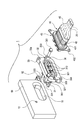
- FIG. 1 is an exploded perspective view of an embodiment of a shield connector according to the present invention.
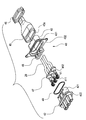
- 2 is an exploded perspective view of the device-side connector shown in FIG.
- FIG. 3 is an exploded perspective view of the cable side connector shown in FIG.
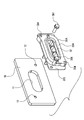
- FIG. 4 is a perspective view of another embodiment of the device-side connector according to the present invention.
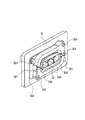
- FIG. 5 is a perspective view of a state in which the device-side connector shown in FIG. 4 is fixed to a shield case.
- FIG. 6 is a perspective view, partly in section, of the device-side connector and shield case shown in FIG. 7 is a longitudinal sectional view of the device-side connector and the shield case shown in FIG.
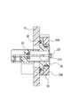
- FIG. 8 is a longitudinal sectional view of a conventional shield connector.
- the shield connector 1 of the present embodiment is a connector for connecting an external cable 20 to a circuit in a shield case 10 of a device mounted on a vehicle or the like.
- the shield connector 1 of the present embodiment includes a device-side connector 30 that is fixed to the shield case 10 and a cable-side connector 40 that is attached to the end of the external cable 20 and is fitted and connected to the device-side connector 30. Yes.
- the shield case 10 is provided with a connector insertion hole 11 and a screw hole 12 for fixing the connector in order to attach the device-side connector 30.
- the connector insertion hole 11 is an opening through which a device-side resin housing 32 of a device-side connector 30 described later is inserted.
- the screw hole 12 is a screw hole into which a bolt 361 for fastening a device-side shield shell 33 of the device-side connector 30 described later is screwed.
- the screw holes 12 are provided at two locations located on the diagonal of the outer periphery of the connector insertion hole 11.
- the external cable 20 is an electric wire that supplies power to a device (not shown) mounted on a vehicle or the like and transmits / receives a signal.
- the external cable 20 connected to the cable-side connector 40 is covered with a tubular braid 45 that electromagnetically shields the periphery of the external cable 20.
- the device-side connector 30 includes a device-side connection terminal 31, a device-side resin housing 32, a device-side shield shell 33, a first packing 34, a second packing 35, and a terminal. Sealing ring 36.
- the device-side connection terminal 31 is made of a metal plate and includes a circuit connection portion 311 at one end and a tongue-like terminal portion 312 at the other end.
- the circuit connection portion 311 is conductively connected to a terminal (not shown) of a circuit in the device by screwing.
- the tongue-like terminal portion 312 is a part that is fitted and connected to the connection terminal on the cable side connector 40 side.
- the device-side resin housing 32 includes a terminal housing cylinder portion 321 that accommodates and holds the device-side connection terminal 31 and a housing flange portion 322 that is formed in a bowl shape on the outer periphery of the terminal accommodation cylinder portion 321.
- the terminal accommodating cylinder portion 321 is set to have an outer shape smaller than the connector insertion hole 11 so as to loosely fit into the connector insertion hole 11.
- the housing flange 322 is set to have an outer shape larger than that of the connector insertion hole 11 so as not to be inserted through the connector insertion hole 11.
- the device-side resin housing 32 has a locking piece 323 for coupling with a device-side shield shell 33 described later. In the state where the device-side resin housing 32 is coupled to the device-side shield shell 33, a later-described cable-side connector 40 can be fitted and connected.
- the device-side shield shell 33 is made of a conductive material and has a locking portion 331 that locks the locking piece 323 of the device-side resin housing 32.
- the device-side shield shell 33 holds the device-side resin housing 32 by electromagnetically shielding the periphery of the device-side resin housing 32 by locking the locking pieces 323 with the locking portions 331.
- the device-side shield shell 33 further includes a case fixing flange portion 333 that is screwed to the outer surface of the shield case 10 in a surface contact state, and a mating shell fixing portion 334. As shown in FIG. 1, the case fixing flange portion 333 is screwed to the shield case 10 by a bolt 361 that is a screw member screwed into the screw hole 12.
- the mating shell fixing part 334 is a screw hole for screwing the cable side connector 40.
- the mating shell fixing portion 334 fastens a later-described cable-side shield shell 43 (see FIG. 3) provided in the cable-side connector 40 in a fitting connection state between the device-side connector 30 and the cable-side connector 40.
- the device-side shield shell 33 and the cable-side shield shell 43 are coupled in a conductive state.
- the mating shell fixing portion 334 is provided in the thick portion 336 located inside the case fixing flange portion 333.
- the thick portion 336 is a thick wall that protrudes outward of the shield case 10 from the protruding height (below neck length) of the bolt 361 that is a screw member for fastening the case fixing flange portion 333 to the shield case 10. It is formed in a shape.
- the thick portion 336 has a fitting portion receiving hole 337 formed through the central portion.
- the fitting portion accommodating hole 337 is a hole for accommodating a terminal accommodating cylinder portion 421 of a cable side resin housing 42 described later in the cable side connector 40. Since the fitting portion accommodation hole 337 is provided, the thick portion 336 functions as a hood portion that accommodates the fitting portion of the cable-side connector 40.
- the mating shell fixing part 334 is equipped on the thick part 336.
- the depth of the screw hole as the mating shell fixing part 334 is set so as not to penetrate the thick part 336.
- the first packing 34 is attached to the rear surface of the outer peripheral edge of the housing flange 322 of the device-side resin housing 32 so as to face the outer surface of the shield case 10.
- the first packing 34 is pressed against the outer surface of the shield case 10 (periphery of the connector insertion hole 11) by screwing the case fixing flange 333 of the device side shield shell 33 to the shield case 10, The space between the side connector 30 and the shield case 10 is sealed.
- the second packing 35 is fitted to the outer periphery of the housing flange 322 of the device-side resin housing 32 so as to face the device-side shield shell 33 by being fitted to the outer periphery of the terminal housing cylinder portion 321. It is done.
- the second packing 35 is sandwiched between the housing flange 322 of the device-side resin housing 32 and the device-side shield shell 33, and seals between the device-side resin housing 32 and the device-side shield shell 33. .
- the terminal seal ring 36 is fitted into the tongue-shaped terminal portion 312 of the device-side connection terminal 31 held by the terminal accommodating cylinder portion 321, and moisture enters the shield case 10 through the tongue-shaped terminal portion 312. To prevent.
- the cable side connector 40 accommodates and holds a cable side connection terminal 41, a cable side resin housing 42 for accommodating and holding the cable side connection terminal 41, and the cable side resin housing 42.
- a cable-side shield shell 43 that can be screwed to the device-side shield shell 33 of the device-side connector 30, a tubular braid 45 that covers the external cable 20 connected to the cable-side connection terminal 41, and a tubular braid 45.
- a braided fixing ring 46 for fixing to the cable-side shield shell 43, a rubber plug 47 attached to the external cable 20 connected to the cable-side connection terminal 41, and attached to the external cable 20 after the rubber plug 47.
- An electric wire holder 48 and a third packing 49 are provided.
- the cable side connection terminal 41 is provided with a terminal fitting portion 411 that is fitted to the tongue-like terminal portion 312 of the device side connection terminal 31 at one end and a wire crimping portion 412 to which the external cable 20 is crimped and connected at the other end. It has been.
- the cable-side resin housing 42 includes a terminal housing cylinder portion 421 that accommodates the cable-side connection terminal 41 and a housing flange portion 422 that is formed in a bowl shape on the outer periphery of the terminal accommodation cylinder portion 421.
- the cable side shield shell 43 includes a cylindrical portion 431 that accommodates the rear end portion of the terminal accommodating cylinder portion 421 and a connector coupling flange portion 432 that is formed in a hook shape at the front end of the cylindrical portion 431.
- the connector coupling flange portion 432 is abutted against the thick portion 336 of the device-side shield shell 33 and is screwed to the mating shell fixing portion 334.
- the cable side connector 40 is coupled to the device side connector 30 by screwing the connector coupling flange portion 432 to the mating shell fixing portion 334.
- the tubular braid 45 covers the outer periphery of the external cable 20 extending behind the cable-side shield shell 43 and electromagnetically shields the periphery of the external cable 20.
- the front end 45 a of the braid 45 has a cylindrical shape that is fitted around the cylindrical portion 431 of the cable-side shield shell 43.
- the braid fixing ring 46 connects the tubular braid 45 to the cable-side shield shell 43 by fastening the tubular braid 45 fitted around the tubular portion 431 of the cable-side shield shell 43 to the tubular portion 431.
- the rubber plug 47 When the cable-side connection terminal 41 is inserted into the terminal accommodation hole formed in the terminal accommodation cylinder portion 421, the rubber plug 47 is tightly fitted into the terminal accommodation hole and passes through the external cable 20 to the terminal accommodation hole side. Prevent water from entering.
- the electric wire holder 48 is held in the cylindrical portion 431 while being fitted to the external cable 20, and restricts the displacement of the external cable 20 in the cylindrical portion 431.
- the third packing 49 is sandwiched between the housing flange portion 422 of the cable-side resin housing 42 and the connector coupling flange portion 432 of the cable-side shield shell 43, so that the cable-side resin housing 42 and the cable-side shield shell are disposed. 43 is sealed.
- the shield connector 1 is attached to the device-side connector 30 fixed to the shield case 10 and the end of the external cable 20 and is fitted and connected to the device-side connector 30. Cable side connector 40. Therefore, attachment / detachment of the external cable 20 to / from the shield case 10 is realized by attaching / detaching the cable-side connector 40 to / from the device-side connector 30.
- the equipment-side connector 30 may remain fixed to the shield case 10, and the equipment-side connector can be used even when the external cable 20 is repeatedly attached to and detached from the shield case 10.
- the first packing 34 that seals between the shield 30 and the shield case 10 is not affected at all.
- the sealing between the shield case 10 and the device-side connector 30 is performed between the case fixing flange portion 333 of the device-side shield shell 33 and the outer surface of the shield case 10.
- the device-side resin housing 32 only needs to be loosely fitted in the connector insertion hole 11 on the shield case 10, and the external dimensions of the device-side resin housing 32 are as follows. The accuracy does not affect the sealing performance at the attachment portion to the shield case 10.
- the change can be dealt with by changing the design of only the device-side shield shell 33 that is attached to the shield case 10, and the device-side resin is used.
- the mating dimension between the housing 32 and the shield shell can be kept as is.
- the design change of the component parts corresponding to the change is small, and the product development corresponding to the change of the mounting dimension on the shield case 10 side can be facilitated. it can.
- the thick portion 336 provided in the device-side shield shell 33 also serves as a hood portion that houses the distal end portion of the cable-side connector 40. 32 does not require the formation of a hood portion that accommodates the distal end portion of the cable-side connector 40, and the structure of the device-side resin housing 32 can be simplified.
- the mating shell fixing portion 334 is provided in the thick wall portion 336, a sufficient length (depth) is secured in the screw hole as the mating shell fixing portion 334, and the device side connector 30 and the cable by screwing are secured.
- the coupling strength with the side connector 40 can be improved.
- FIG. 4 is a perspective view of another embodiment of the device-side connector according to the present invention
- FIG. 5 is a perspective view of the device-side connector shown in FIG. 4 fixed to a shield case
- FIG. 6 is the device shown in FIG.
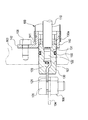
- FIG. 7 is a longitudinal sectional view of the device-side connector and the shield case shown in FIG. 5.
- the device-side connector 30A of this other embodiment is different from the device-side connector 30 of one embodiment in that a part of the device-side shield shell 33 is used instead of the device-side shield shell 33 of one embodiment described above. This is the point of adopting the device-side shield shell 33A whose design has been changed.
- the device-side shield shell 33A is a design change in the shape of the case fixing flange portion 333 corresponding to the change in the arrangement of the screw holes 12 in the shield case 10.
- the components other than the device-side shield shell 33A may be the same as those in the above-described embodiment.
- the design change of the component parts corresponding to the change is small, and the shield case 10 side
- the product development corresponding to the change of the mounting dimension can be facilitated.
- this invention is not limited to embodiment mentioned above, A deformation
- the material, shape, dimensions, number, arrangement location, and the like of each component in the above-described embodiment are arbitrary and are not limited as long as the present invention can be achieved. Note that this application is based on a Japanese patent application filed on March 31, 2011 (Japanese Patent Application No. 2011-079772), the contents of which are incorporated herein by reference.
- the equipment side connector when the external cable is attached to or detached from the shield case, the equipment side connector may remain fixed to the shield case, and even if the external cable is repeatedly attached to and detached from the shield case, the equipment side connector
- the first packing that seals between the shield case and the shield case has no effect. Therefore, even if the external cable is repeatedly attached to and detached from the shield case, the sealing performance at the attachment portion to the shield case does not deteriorate.
- the mounting dimensions on the shield case side when the mounting dimensions on the shield case side are changed, the change can be dealt with by changing the design of only the shield shell that is attached to the shield case. The mating dimensions of can be kept as they were in the past. Therefore, when the mounting dimension on the shield case side is changed, the design change of the component parts corresponding to the change is small, and the product development corresponding to the change of the mounting dimension on the shield case side can be facilitated.
Abstract
シールドケース(10)に固定される機器側コネクタ(30)と、外部ケーブル(20)の端部に取り付けられて機器側コネクタ(30)に嵌合接続されるケーブル側コネクタ(40)とを備える。機器側コネクタ(30)は、機器側接続端子(31)と、機器側樹脂製ハウジング(32)と、機器側シールドシェル(33)と、を備える。機器側シールドシェル(33)には、機器側シールドシェル(33)とケーブル側シールドシェル(43)とを導通状態に結合する相手シェル固定部(334)を備える。
Description
本発明は、機器のシールドケース内の回路に外部ケーブルを接続するシールドコネクタに関する。
図8は、シールドコネクタの従来例を示している。このシールドコネクタ100は、下記特許文献1に開示されたものである。
このシールドコネクタ100は、車両等に搭載される機器のシールドケース103内の回路に外部ケーブル110を接続するコネクタである。
このシールドコネクタ100は、外部ケーブル110の先端に圧着接続されるケーブル側接続端子120と、このケーブル側接続端子120を収容保持する樹脂製ハウジング130と、樹脂製ハウジング130を保持してシールドケース103にねじ止めされるシールドシェル140と、当該シールドコネクタ100とシールドケース103との間を封止するパッキン150とを備えている。
ケーブル側接続端子120は、図8に示すように、一端に舌状端子部121を備えると共に、他端に電線圧着部122を備えている。舌状端子部121は、図8に示すように、シールドケース103内の回路の舌状端子104にねじ部材105,106を介して接続される部位である。電線圧着部122は、外部ケーブル110の端部に圧着接続される部位である。
樹脂製ハウジング130は、モールド成形により、ケーブル側接続端子120を収容した形態に一体形成される。樹脂製ハウジング130の外形は、シールドケース103に貫通形成されたコネクタ挿通孔107に挿通可能な柱状である。そして、樹脂製ハウジング130の外周には、パッキン150を装着するパッキン装着溝131が、外周を一周する環状に形成されている。
シールドシェル140は、外部ケーブル110の端部を収容した樹脂製ハウジング130の基端部130aを保持する筒状のシェル本体141と、シェル本体141のシールドケース103側の端部から鍔状に張り出して設けられたケース固定用フランジ部142とを備える。ケース固定用フランジ部142は、シールドケース103の外面に面接触状態に突き合され、ボルト108によりシールドケース103にねじ止めされる。ケース固定用フランジ部142をシールドケース103にねじ止めすることで、シールドコネクタ100がシールドケース103に固定された状態になる。
パッキン150は、樹脂製ハウジング130のパッキン装着溝131に装着されるリング状のパッキンである。このパッキン150は、コネクタ挿通孔107の内周面と樹脂製ハウジング130の外周面との間の隙間を塞いで、シールドコネクタ100とシールドケース103との間を封止する。
ところが、特許文献1に開示のシールドコネクタ100は、コネクタ挿通孔107を挿通する樹脂製ハウジング130の外周に装備したリング状のパッキン150が、コネクタ挿通孔107の内周面に密着させられることで、シールドコネクタ100とシールドケース103との間を封止する構成である。そのため、シールドケース103に対して外部ケーブル110の着脱を繰り返すと、パッキン150がコネクタ挿通孔107との摺動で傷み易く、シールドケース103への取付け部におけるシール性能が低下するおそれがあった。
また、ボルト108を螺合させるシールドケース103上のねじ穴109の配置の変更、或いはコネクタ挿通孔107の形状や寸法の変更といったシールドケース103上の取付寸法が変更されると、その変更に対応するためには、シールドシェル140だけでなく、コネクタ挿通孔107に緊密嵌合させる樹脂製ハウジング130やパッキン150についても、設計変更が必要となる。即ち、シールドケース103側の取付寸法が変更されると、多数の構成部品に設計変更が必要となり、シールドケース側の取付寸法の変更に対応する製品開発に多大な労力が必要となるという問題もあった。
そこで、本発明の目的は、上記課題を解消することに係り、シールドケースに対して外部ケーブルの着脱を繰り返しても、シールドケースへの取付け部におけるシール性能が低下することがなく、しかも、シールドケース側の取付寸法の変更に対応する製品開発を容易にすることができるシールドコネクタを提供することにある。
本発明の前述した目的は、下記の構成により達成される。
(1)機器のシールドケース内の回路に外部ケーブルを接続するシールドコネクタであって、
前記シールドケースに固定される機器側コネクタと、前記外部ケーブルの端部に取り付けられて前記機器側コネクタに嵌合接続されるケーブル側コネクタとを備え、
前記機器側コネクタは、
一端が前記シールドケース内の回路に接続されると共に他端が前記ケーブル側コネクタ側の接続端子に嵌合接続される機器側接続端子と、
該機器側接続端子を収容保持すると共に前記ケーブル側コネクタを嵌合接続可能な機器側樹脂製ハウジングと、
前記機器側樹脂製ハウジングを保持すると共に、前記シールドケースの外面に面接触状態でねじ止めされるケース固定用フランジ部を有した機器側シールドシェルと、
前記ケース固定用フランジ部の前記シールドケースへのねじ止めにより前記シールドケースの外面に押圧されて前記機器側コネクタと前記シールドケースとの間を封止する第1のパッキンと、を備え、
前記機器側シールドシェルには、前記ケーブル側コネクタに装備されたケーブル側シールドシェルを締結することで、前記機器側シールドシェルと前記ケーブル側シールドシェルとを導通状態に結合する相手シェル固定部を備えたシールドコネクタ。
(2)前記機器側シールドシェルには、前記ケース固定用フランジ部を前記シールドケースに締結するねじ部材の突出高さよりも前記シールドケースの外方側に突出する厚肉状に形成されると共に、前記ケーブル側コネクタの嵌合部を収容するフード部として機能する厚肉部が設けられ、
前記厚肉部に前記相手シェル固定部が装備された上記(1)に記載のシールドコネクタ。
前記厚肉部に前記相手シェル固定部が装備された上記(1)に記載のシールドコネクタ。
上記(1)の構成によれば、シールドコネクタは、シールドケースに固定される機器側コネクタと、外部ケーブルの端部に取り付けられて機器側コネクタに嵌合接続されるケーブル側コネクタとから構成されている。そのため、シールドケースに対する外部ケーブルの着脱は、機器側コネクタに対してケーブル側コネクタを着脱することで実現する。
換言すると、シールドケースに対する外部ケーブルの着脱時に、機器側コネクタはシールドケースに固定した状態のままで良く、シールドケースに対して外部ケーブルの着脱を繰り返しても、機器側コネクタとシールドケースとの間を封止している第1のパッキンには、全く影響が及ばない。
従って、シールドケースに対して外部ケーブルの着脱を繰り返しても、シールドケースへの取付け部におけるシール性能が低下することがない。
しかも、シールドケースと機器側コネクタとの間の封止は、シールドシェルのケース固定用フランジ部とシールドケースの外面との間に挟持される第1のパッキンにより行っており、機器側樹脂製ハウジングはシールドケース上のコネクタ挿通孔に遊嵌させるだけでよく、機器側樹脂製ハウジングの外形の寸法精度はシールドケースへの取付け部におけるシール性能に影響しない。
そのため、シールドケース側の取付寸法が変更される場合に、その変更への対応は、シールドケースへの取り付けを果たすシールドシェルだけの設計変更で済ませることができ、機器側樹脂製ハウジングとシールドシェルとの取り合い寸法は従来のままに留めることができる。
従って、シールドケース側の取付寸法の変更に際して、その変更に対応するための構成部品の設計変更が少なくて済み、シールドケース側の取付寸法の変更に対応する製品開発を容易にすることもできる。
上記(2)の構成によれば、シールドシェルに装備した厚肉部が、ケーブル側コネクタの先端部を収容するフード部を兼ねるため、機器側樹脂製ハウジングには、ケーブル側コネクタの先端部を収容するフード部の形成が不要になり、機器側樹脂製ハウジングの構造を単純化することができる。
更に、厚肉部に相手シェル固定部が装備されるため、相手シェル固定部としてのねじ穴に十分な長さを確保して、螺合による結合強度を向上させることができる。
以下、本発明に係るシールドコネクタの好適な実施形態について、図面を参照して詳細に説明する。
図1~図3に示すように、本実施形態のシールドコネクタ1は、車両等に搭載される機器のシールドケース10内の回路に外部ケーブル20を接続するコネクタである。
本実施形態のシールドコネクタ1は、シールドケース10に固定される機器側コネクタ30と、外部ケーブル20の端部に取り付けられて機器側コネクタ30に嵌合接続されるケーブル側コネクタ40とを備えている。
本実施形態のシールドコネクタ1は、シールドケース10に固定される機器側コネクタ30と、外部ケーブル20の端部に取り付けられて機器側コネクタ30に嵌合接続されるケーブル側コネクタ40とを備えている。
シールドケース10は、機器側コネクタ30を取り付けるために、コネクタ挿通孔11と、コネクタ固定用のねじ穴12とが形成されている。コネクタ挿通孔11は、後述の機器側コネクタ30の機器側樹脂製ハウジング32を挿通させるための開口である。また、ねじ穴12は、後述する機器側コネクタ30の機器側シールドシェル33を締結するボルト361が螺合するねじ穴である。ねじ穴12は、コネクタ挿通孔11の外周の対角に位置する2箇所に装備されている。
外部ケーブル20は、車両等に搭載される不図示の機器への給電や、信号の送受を行う電線である。ケーブル側コネクタ40に接続される外部ケーブル20には、外部ケーブル20の周囲を電磁遮蔽するチューブ状の編組45が被せられる。
機器側コネクタ30は、図2に示すように、機器側接続端子31と、機器側樹脂製ハウジング32と、機器側シールドシェル33と、第1のパッキン34と、第2のパッキン35と、端子用シールリング36と、を備える。
機器側接続端子31は、金属板製で、一端に回路接続部311を備えると共に、他端に舌状端子部312を備えている。回路接続部311は、機器内の回路の不図示の端子にねじ止めにより導通接続される。舌状端子部312は、ケーブル側コネクタ40側の接続端子に嵌合接続される部位である。
機器側樹脂製ハウジング32は、機器側接続端子31を収容保持する端子収容筒部321と、端子収容筒部321の外周に鍔状に形成されたハウジング鍔部322とを備えている。端子収容筒部321は、コネクタ挿通孔11に遊嵌するように、外形がコネクタ挿通孔11よりも小さく設定されている。また、ハウジング鍔部322は、コネクタ挿通孔11を挿通しないように、外形がコネクタ挿通孔11よりも大きく設定されている。
また、機器側樹脂製ハウジング32は、後述の機器側シールドシェル33と結合するための係止片323を有している。機器側樹脂製ハウジング32は、機器側シールドシェル33に結合した状態では、後述のケーブル側コネクタ40を嵌合接続可能である。
機器側シールドシェル33は、導電材料製で、機器側樹脂製ハウジング32の係止片323を係止する係止部331を有している。機器側シールドシェル33は、係止片323を係止部331で係止することにより、機器側樹脂製ハウジング32を保持し、機器側樹脂製ハウジング32の周囲を電磁遮蔽する。
更に、機器側シールドシェル33は、シールドケース10の外面に面接触状態でねじ止めされるケース固定用フランジ部333と、相手シェル固定部334と、を備える。
ケース固定用フランジ部333は、図1に示すように、ねじ穴12に螺合するねじ部材であるボルト361により、シールドケース10にねじ止めされる。
ケース固定用フランジ部333は、図1に示すように、ねじ穴12に螺合するねじ部材であるボルト361により、シールドケース10にねじ止めされる。
相手シェル固定部334は、ケーブル側コネクタ40をねじ止めするねじ穴である。この相手シェル固定部334は、機器側コネクタ30とケーブル側コネクタ40との嵌合接続状態において、ケーブル側コネクタ40に装備された後述のケーブル側シールドシェル43(図3参照)を締結することで、機器側シールドシェル33とケーブル側シールドシェル43とを導通状態に結合する。
本実施形態の場合、相手シェル固定部334は、ケース固定用フランジ部333の内側に位置する厚肉部336に装備されている。
この厚肉部336は、ケース固定用フランジ部333をシールドケース10に締結するねじ部材であるボルト361の突出高さ(首下長さ)よりもシールドケース10の外方側に突出する厚肉状に形成されている。
更に、この厚肉部336は、中央部に、嵌合部収容孔337が貫通形成されている。この嵌合部収容孔337は、ケーブル側コネクタ40における後述するケーブル側樹脂製ハウジング42の端子収容筒部421を収容する孔である。嵌合部収容孔337を装備したことで、厚肉部336は、ケーブル側コネクタ40の嵌合部を収容するフード部として機能する。
本実施形態の場合、相手シェル固定部334は、厚肉部336に装備されている。相手シェル固定部334としてのねじ穴は、厚肉部336を貫通しないように、深さが設定されている。
第1のパッキン34は、シールドケース10の外面と対向するように、機器側樹脂製ハウジング32のハウジング鍔部322の外周縁の後面に、取り付けられる。
この第1のパッキン34は、機器側シールドシェル33におけるケース固定用フランジ部333のシールドケース10へのねじ止めにより、シールドケース10の外面(コネクタ挿通孔11の周縁部)に押圧されて、機器側コネクタ30とシールドケース10との間を封止する。
第2のパッキン35は、機器側シールドシェル33と対向するように、機器側樹脂製ハウジング32のハウジング鍔部322の外周縁の前面側に、端子収容筒部321の外周に嵌合して取り付けられる。
この第2のパッキン35は、機器側樹脂製ハウジング32のハウジング鍔部322と機器側シールドシェル33とに挟持されて、機器側樹脂製ハウジング32と機器側シールドシェル33との間を封止する。
端子用シールリング36は、端子収容筒部321に保持されている機器側接続端子31の舌状端子部312に嵌合して、舌状端子部312を伝って水分がシールドケース10内に浸入することを防止する。
次に、機器側コネクタ30に嵌合接続されるケーブル側コネクタ40の構成を図3に基づいて説明する。
ケーブル側コネクタ40は、図3に示すように、ケーブル側接続端子41と、該ケーブル側接続端子41を収容保持するケーブル側樹脂製ハウジング42と、該ケーブル側樹脂製ハウジング42を収容保持して機器側コネクタ30の機器側シールドシェル33にねじ止め可能なケーブル側シールドシェル43と、ケーブル側接続端子41に接続される外部ケーブル20に被せられるチューブ状の編組45と、チューブ状の編組45をケーブル側シールドシェル43に固定するための編組固定リング46と、ケーブル側接続端子41に接続された外部ケーブル20に装着されるゴム栓47と、ゴム栓47の後段で外部ケーブル20に装着される電線ホルダ48と、第3のパッキン49とを備えている。
ケーブル側接続端子41は、一端に機器側接続端子31の舌状端子部312に嵌合する端子嵌合部411が備えられ、他端に外部ケーブル20が圧着接続される電線圧着部412が備えられている。
ケーブル側樹脂製ハウジング42は、ケーブル側接続端子41を収容する端子収容筒部421と、端子収容筒部421の外周に鍔状に形成されたハウジング鍔部422とを備えている。
ケーブル側シールドシェル43は、端子収容筒部421の後端部を収容する筒状部431と、筒状部431の前端に鍔状に形成されたコネクタ結合用フランジ部432とを備える。コネクタ結合用フランジ部432は、機器側シールドシェル33の厚肉部336に突き当てられ、相手シェル固定部334にねじ止めされる。コネクタ結合用フランジ部432を相手シェル固定部334にねじ止めすることにより、ケーブル側コネクタ40が機器側コネクタ30に結合される。
チューブ状の編組45は、ケーブル側シールドシェル43の後方に延出する外部ケーブル20の外周を覆って、外部ケーブル20の周囲を電磁遮蔽する。編組45の先端45aは、ケーブル側シールドシェル43の筒状部431に外嵌する筒状になっている。
編組固定リング46は、ケーブル側シールドシェル43の筒状部431に外嵌したチューブ状の編組45を筒状部431に締め付けて、チューブ状の編組45をケーブル側シールドシェル43に連結する。
ゴム栓47は、ケーブル側接続端子41を端子収容筒部421に形成された端子収容孔に挿入したときに、端子収容孔に緊密嵌合して、外部ケーブル20を伝って端子収容孔側に水が浸入することを防止する。
電線ホルダ48は、外部ケーブル20に嵌合装着された状態で筒状部431内に保持され、筒状部431内での外部ケーブル20の変位を規制する。
第3のパッキン49は、ケーブル側樹脂製ハウジング42のハウジング鍔部422とケーブル側シールドシェル43のコネクタ結合用フランジ部432との間に挟持されて、ケーブル側樹脂製ハウジング42とケーブル側シールドシェル43との間を封止する。
以上に説明した一実施形態のシールドコネクタ1では、シールドコネクタ1が、シールドケース10に固定される機器側コネクタ30と、外部ケーブル20の端部に取り付けられて機器側コネクタ30に嵌合接続されるケーブル側コネクタ40とから構成されている。そのため、シールドケース10に対する外部ケーブル20の着脱は、機器側コネクタ30に対してケーブル側コネクタ40を着脱することで実現する。
換言すると、シールドケース10に対する外部ケーブル20の着脱時に、機器側コネクタ30はシールドケース10に固定した状態のままで良く、シールドケース10に対して外部ケーブル20の着脱を繰り返しても、機器側コネクタ30とシールドケース10との間を封止している第1のパッキン34には、全く影響が及ばない。
従って、シールドケース10に対して外部ケーブル20の着脱を繰り返しても、シールドケース10への取付け部におけるシール性能が低下することがない。
しかも、以上に説明した一実施形態のシールドコネクタ1では、シールドケース10と機器側コネクタ30との間の封止は、機器側シールドシェル33のケース固定用フランジ部333とシールドケース10の外面との間に挟持される第1のパッキン34により行っており、機器側樹脂製ハウジング32はシールドケース10上のコネクタ挿通孔11に遊嵌させるだけでよく、機器側樹脂製ハウジング32の外形の寸法精度はシールドケース10への取付け部におけるシール性能に影響しない。
そのため、シールドケース10側の取付寸法が変更される場合に、その変更への対応は、シールドケース10への取り付けを果たす機器側シールドシェル33だけの設計変更で済ませることができ、機器側樹脂製ハウジング32とシールドシェルとの取り合い寸法は従来のままに留めることができる。
従って、シールドケース10側の取付寸法の変更に際して、その変更に対応するための構成部品の設計変更が少なくて済み、シールドケース10側の取付寸法の変更に対応する製品開発を容易にすることもできる。
更に、以上に説明した一実施形態のシールドコネクタ1では、機器側シールドシェル33に装備した厚肉部336が、ケーブル側コネクタ40の先端部を収容するフード部を兼ねるため、機器側樹脂製ハウジング32には、ケーブル側コネクタ40の先端部を収容するフード部の形成が不要になり、機器側樹脂製ハウジング32の構造を単純化することができる。
更に、厚肉部336に相手シェル固定部334が装備されるため、相手シェル固定部334としてのねじ穴に十分な長さ(深さ)を確保して、螺合による機器側コネクタ30とケーブル側コネクタ40との間の結合強度を向上させることができる。
図4~図7は、本発明に係るシールドコネクタにおける機器側コネクタの他の実施形態を示している。
図4は本発明に係る機器側コネクタの他の実施形態の斜視図、図5は図4に示した機器側コネクタをシールドケースに固定した状態の斜視図、図6は図5に示した機器側コネクタとシールドケースを一部断面にした斜視図、図7は図5に示した機器側コネクタとシールドケースの縦断面図である。
この他の実施形態の機器側コネクタ30Aが一実施形態の機器側コネクタ30と相異する点は、上述した一実施形態の機器側シールドシェル33の代わりに、機器側シールドシェル33の一部を設計変更した機器側シールドシェル33Aを採用した点である。
機器側シールドシェル33Aは、シールドケース10におけるねじ穴12の配置変更に対応して、ケース固定用フランジ部333の形状を設計変更したものである。
機器側コネクタ30Aを構成する構成部品の内、機器側シールドシェル33A以外の構成部品は、上述した一実施形態のものと共通でよい。
この他の実施形態でも明らかなように、本発明のシールドコネクタでは、シールドケース10側の取付寸法の変更に際して、その変更に対応するための構成部品の設計変更が少なくて済み、シールドケース10側の取付寸法の変更に対応する製品開発を容易にすることができる。
なお、本発明は、上述した実施形態に限定されるものではなく、適宜、変形、改良、等が可能である。その他、上述した実施形態における各構成要素の材質、形状、寸法、数、配置箇所、等は本発明を達成できるものであれば任意であり、限定されない。
なお、本出願は、2011年3月31日出願の日本特許出願(特願2011-079572)に基づくものであり、その内容はここに参照として取り込まれる。
なお、本出願は、2011年3月31日出願の日本特許出願(特願2011-079572)に基づくものであり、その内容はここに参照として取り込まれる。
本発明によるシールドコネクタによれば、シールドケースに対する外部ケーブルの着脱時に、機器側コネクタはシールドケースに固定した状態のままで良く、シールドケースに対して外部ケーブルの着脱を繰り返しても、機器側コネクタとシールドケースとの間を封止している第1のパッキンには、全く影響が及ばない。
従って、シールドケースに対して外部ケーブルの着脱を繰り返しても、シールドケースへの取付け部におけるシール性能が低下することがない。
しかも、シールドケース側の取付寸法が変更される場合に、その変更への対応は、シールドケースへの取り付けを果たすシールドシェルだけの設計変更で済ませることができ、機器側樹脂製ハウジングとシールドシェルとの取り合い寸法は従来のままに留めることができる。
従って、シールドケース側の取付寸法の変更に際して、その変更に対応するための構成部品の設計変更が少なくて済み、シールドケース側の取付寸法の変更に対応する製品開発を容易にすることもできる。
従って、シールドケースに対して外部ケーブルの着脱を繰り返しても、シールドケースへの取付け部におけるシール性能が低下することがない。
しかも、シールドケース側の取付寸法が変更される場合に、その変更への対応は、シールドケースへの取り付けを果たすシールドシェルだけの設計変更で済ませることができ、機器側樹脂製ハウジングとシールドシェルとの取り合い寸法は従来のままに留めることができる。
従って、シールドケース側の取付寸法の変更に際して、その変更に対応するための構成部品の設計変更が少なくて済み、シールドケース側の取付寸法の変更に対応する製品開発を容易にすることもできる。
1 シールドコネクタ
10 シールドケース
20 外部ケーブル
30 機器側コネクタ
31 機器側接続端子
32 機器側樹脂製ハウジング
33 機器側シールドシェル
334 相手シェル固定部
34 第1のパッキン
40 ケーブル側コネクタ
43 ケーブル側シールドシェル
45 編組
10 シールドケース
20 外部ケーブル
30 機器側コネクタ
31 機器側接続端子
32 機器側樹脂製ハウジング
33 機器側シールドシェル
334 相手シェル固定部
34 第1のパッキン
40 ケーブル側コネクタ
43 ケーブル側シールドシェル
45 編組
Claims (2)
- 機器のシールドケース内の回路に外部ケーブルを接続するシールドコネクタであって、
前記シールドケースに固定される機器側コネクタと、前記外部ケーブルの端部に取り付けられて前記機器側コネクタに嵌合接続されるケーブル側コネクタとを備え、
前記機器側コネクタは、
一端が前記シールドケース内の回路に接続されると共に他端が前記ケーブル側コネクタ側の接続端子に嵌合接続される機器側接続端子と、
該機器側接続端子を収容保持すると共に前記ケーブル側コネクタを嵌合接続可能な機器側樹脂製ハウジングと、
前記機器側樹脂製ハウジングを保持すると共に、前記シールドケースの外面に面接触状態でねじ止めされるケース固定用フランジ部を有した機器側シールドシェルと、
前記ケース固定用フランジ部の前記シールドケースへのねじ止めにより前記シールドケースの外面に押圧されて前記機器側コネクタと前記シールドケースとの間を封止する第1のパッキンと、を備え、
前記機器側シールドシェルには、前記ケーブル側コネクタに装備されたケーブル側シールドシェルを締結することで、前記機器側シールドシェルと前記ケーブル側シールドシェルとを導通状態に結合する相手シェル固定部を備えたシールドコネクタ。 - 前記機器側シールドシェルには、前記ケース固定用フランジ部を前記シールドケースに締結するねじ部材の突出高さよりも前記シールドケースの外方側に突出する厚肉状に形成されると共に、前記ケーブル側コネクタの嵌合部を収容するフード部として機能する厚肉部が設けられ、
前記厚肉部に前記相手シェル固定部が装備された請求項1に記載のシールドコネクタ。
Priority Applications (3)
| Application Number | Priority Date | Filing Date | Title |
|---|---|---|---|
| EP12764081.1A EP2693574B1 (en) | 2011-03-31 | 2012-03-27 | Shield connector |
| CN201280015790.XA CN103460517B (zh) | 2011-03-31 | 2012-03-27 | 屏蔽连接器 |
| US14/039,865 US8992249B2 (en) | 2011-03-31 | 2013-09-27 | Shielded connector |
Applications Claiming Priority (2)
| Application Number | Priority Date | Filing Date | Title |
|---|---|---|---|
| JP2011-079572 | 2011-03-31 | ||
| JP2011079572A JP5727839B2 (ja) | 2011-03-31 | 2011-03-31 | シールドコネクタ |
Related Child Applications (1)
| Application Number | Title | Priority Date | Filing Date |
|---|---|---|---|
| US14/039,865 Continuation US8992249B2 (en) | 2011-03-31 | 2013-09-27 | Shielded connector |
Publications (1)
| Publication Number | Publication Date |
|---|---|
| WO2012133460A1 true WO2012133460A1 (ja) | 2012-10-04 |
Family
ID=46931172
Family Applications (1)
| Application Number | Title | Priority Date | Filing Date |
|---|---|---|---|
| PCT/JP2012/058012 WO2012133460A1 (ja) | 2011-03-31 | 2012-03-27 | シールドコネクタ |
Country Status (5)
| Country | Link |
|---|---|
| US (1) | US8992249B2 (ja) |
| EP (1) | EP2693574B1 (ja) |
| JP (1) | JP5727839B2 (ja) |
| CN (1) | CN103460517B (ja) |
| WO (1) | WO2012133460A1 (ja) |
Cited By (4)
| Publication number | Priority date | Publication date | Assignee | Title |
|---|---|---|---|---|
| WO2015041041A1 (ja) * | 2013-09-20 | 2015-03-26 | 株式会社豊田自動織機 | コネクタ |
| CN105122556A (zh) * | 2013-04-15 | 2015-12-02 | 矢崎总业株式会社 | 树脂模制件和防水屏蔽连接器 |
| WO2019077722A1 (ja) * | 2017-10-19 | 2019-04-25 | 三菱電機株式会社 | 防水型コネクタおよびその組立方法 |
| DE102018208334B4 (de) | 2017-06-02 | 2023-08-03 | Yazaki Corporation | Verbindungseinrichtungsmontagestruktur und anschlussstufe |
Families Citing this family (50)
| Publication number | Priority date | Publication date | Assignee | Title |
|---|---|---|---|---|
| US9318849B2 (en) * | 2011-04-14 | 2016-04-19 | Yazaki Corporation | Shielded connector |
| JP5938212B2 (ja) * | 2011-12-28 | 2016-06-22 | 矢崎総業株式会社 | シールドコネクタ装置 |
| JP5985971B2 (ja) * | 2012-12-05 | 2016-09-06 | 日本航空電子工業株式会社 | 防水コネクタ |
| CN103390843B (zh) * | 2013-07-22 | 2015-06-17 | 苏州科宝电气有限公司 | 新能源汽车电机接口接插件 |
| JP6056720B2 (ja) * | 2013-09-18 | 2017-01-11 | 住友電装株式会社 | 機器用コネクタ |
| JP6243693B2 (ja) * | 2013-10-07 | 2017-12-06 | 矢崎総業株式会社 | コネクタ |
| JP6159218B2 (ja) * | 2013-10-11 | 2017-07-05 | 矢崎総業株式会社 | シールドシェル |
| US9640885B2 (en) | 2013-11-17 | 2017-05-02 | Apple Inc. | Connector receptacle having a tongue |
| US9537263B2 (en) | 2013-11-17 | 2017-01-03 | Apple Inc. | Connector receptacle having a shield |
| WO2016144285A2 (en) * | 2013-12-13 | 2016-09-15 | Hewlett Packard Enterprise Development Lp | Connector with a retainer assembly |
| US9379477B2 (en) * | 2013-12-20 | 2016-06-28 | Dai-Ichi Seiko Co., Ltd. | Seal having a packing portion extending from a flat portion with a step |
| US9450339B2 (en) | 2014-01-12 | 2016-09-20 | Apple Inc. | Ground contacts for reduced-length connector inserts |
| US9276340B2 (en) | 2014-05-26 | 2016-03-01 | Apple Inc. | Interposers for connecting receptacle tongues to printed circuit boards |
| US9490581B2 (en) * | 2014-05-26 | 2016-11-08 | Apple Inc. | Connector insert assembly |
| US9356370B2 (en) | 2014-05-26 | 2016-05-31 | Apple Inc. | Interposer for connecting a receptacle tongue to a printed circuit board |
| US9515439B2 (en) | 2014-05-26 | 2016-12-06 | Apple Inc. | Connector insert assembly |
| US10418763B2 (en) | 2014-05-26 | 2019-09-17 | Apple Inc. | Connector insert assembly |
| US9331405B2 (en) * | 2014-06-03 | 2016-05-03 | Tyco Electronics Corporation | Interface connector |
| CN104158027B (zh) * | 2014-08-18 | 2016-07-06 | 四川永贵科技有限公司 | 高压带屏蔽电连接器插座 |
| US9240656B1 (en) * | 2014-08-28 | 2016-01-19 | Tyco Electronics Corporation | Connector assembly with cable bundle |
| JP6413799B2 (ja) | 2015-01-28 | 2018-10-31 | 住友電装株式会社 | 機器用コネクタ |
| JP6727756B2 (ja) * | 2015-03-13 | 2020-07-22 | スリーエム イノベイティブ プロパティズ カンパニー | コネクタ付きケーブルアセンブリ、及びコネクタアセンブリ |
| JP6492929B2 (ja) * | 2015-04-23 | 2019-04-03 | 住友電装株式会社 | コネクタ |
| JP6205397B2 (ja) * | 2015-10-28 | 2017-09-27 | 住友電装株式会社 | シールドコネクタ |
| JP6610954B2 (ja) * | 2016-06-01 | 2019-11-27 | 住友電装株式会社 | シールドコネクタ |
| JP2018085172A (ja) * | 2016-11-21 | 2018-05-31 | 住友電装株式会社 | 充電用インレット |
| CN106654733A (zh) * | 2016-12-21 | 2017-05-10 | 丹阳特瑞莱电子有限公司 | 一种抗电磁干扰的射频连接器 |
| CN106711718B (zh) * | 2017-01-24 | 2022-10-28 | 广东美芝制冷设备有限公司 | 用于车载压缩机的高低压连接插座和车载压缩机 |
| WO2019054090A1 (ja) * | 2017-09-15 | 2019-03-21 | 日本電産株式会社 | モータ及び電動パワーステアリング装置 |
| US10193281B1 (en) * | 2017-10-06 | 2019-01-29 | Te Connectivity Corporation | Electrical connector assembly having a shield assembly |
| JP6939612B2 (ja) * | 2018-02-01 | 2021-09-22 | 住友電装株式会社 | 防水コネクタ |
| CN108376871A (zh) * | 2018-02-09 | 2018-08-07 | 佛山市和富创电子科技有限公司 | 一种端子设备连接器装置 |
| CN110212327A (zh) * | 2018-02-28 | 2019-09-06 | 中航光电科技股份有限公司 | 插座连接器壳体及插座连接器 |
| US10355398B1 (en) * | 2018-03-09 | 2019-07-16 | Yazaki North America, Inc. | Vibration limiting compression protrusions |
| JP6814768B2 (ja) * | 2018-06-15 | 2021-01-20 | 矢崎総業株式会社 | 防液コネクタ |
| US11339823B2 (en) | 2018-08-09 | 2022-05-24 | J.S.T. Corporation | System and method for sealing a metal fastener from electrolyte in an area of dissimilar metals |
| US10811811B2 (en) * | 2018-09-11 | 2020-10-20 | Zhejiang Qicheng Electrical Equipment Co., Ltd. | Socket of optical controller and waterproof sealing socket of optical controller |
| JP6835792B2 (ja) * | 2018-10-29 | 2021-02-24 | 矢崎総業株式会社 | 電気接続箱のアース接続構造および電気接続箱 |
| CN109586101A (zh) * | 2018-11-22 | 2019-04-05 | 英业达科技有限公司 | 连接器组件及电子装置 |
| US10923863B2 (en) | 2018-12-04 | 2021-02-16 | J.S.T. Corporation | High voltage connector and method for assembling thereof |
| US10923860B2 (en) | 2019-02-25 | 2021-02-16 | J.S.T. Corporation | Method for shielding and grounding a connector assembly from electromagnetic interference (EMI) using conductive seal and conductive housing |
| US10804655B2 (en) | 2019-02-28 | 2020-10-13 | J.S.T. Corporation | Method for electromagnetic interference (EMI) protection for a connector assembly using a conductive seal |
| JP6898380B2 (ja) * | 2019-04-04 | 2021-07-07 | 矢崎総業株式会社 | コネクタ |
| DE102019205115B3 (de) * | 2019-04-10 | 2020-08-13 | Icotek Project Gmbh & Co. Kg | Vorrichtung zur Einführung von Leitungen durch eine Öffnung |
| JP2020202036A (ja) * | 2019-06-06 | 2020-12-17 | 株式会社オートネットワーク技術研究所 | シールドコネクタ |
| CN211265834U (zh) * | 2020-03-04 | 2020-08-14 | 东莞崧腾电子有限公司 | 高压连接器 |
| JP7256155B2 (ja) * | 2020-09-30 | 2023-04-11 | 矢崎総業株式会社 | コネクタ |
| JP2022077602A (ja) * | 2020-11-12 | 2022-05-24 | 住友電装株式会社 | コネクタ |
| JP7307125B2 (ja) * | 2021-07-14 | 2023-07-11 | 矢崎総業株式会社 | シールドケーブルの止水構造および止水部品 |
| EP4290162A1 (en) * | 2022-06-09 | 2023-12-13 | BSH Hausgeräte GmbH | Domestic cooling appliance comprising a reinforcement part |
Citations (3)
| Publication number | Priority date | Publication date | Assignee | Title |
|---|---|---|---|---|
| JP2002373737A (ja) | 2001-04-11 | 2002-12-26 | Auto Network Gijutsu Kenkyusho:Kk | 機器用シールドコネクタ |
| JP2005011647A (ja) * | 2003-06-18 | 2005-01-13 | Auto Network Gijutsu Kenkyusho:Kk | コネクタの接続構造及びシールドコネクタ |
| JP2005327557A (ja) * | 2004-05-13 | 2005-11-24 | Hitachi Cable Ltd | ケース用の電源接続具 |
Family Cites Families (18)
| Publication number | Priority date | Publication date | Assignee | Title |
|---|---|---|---|---|
| BE625861A (ja) * | 1961-12-08 | |||
| FR2527389A1 (fr) * | 1982-05-19 | 1983-11-25 | Souriau & Cie | Perfectionnements apportes aux connecteurs electriques, destines notamment a etre utilises dans un milieu liquide en particulier sous pression |
| US4767351A (en) * | 1986-08-13 | 1988-08-30 | G & W Electric Company | High voltage externally-separable bushing |
| US5092791A (en) * | 1989-11-28 | 1992-03-03 | L-Com, Inc. | Bulkhead feedthrough adaptor for IEEEE-488 cables |
| US5066246A (en) * | 1990-11-27 | 1991-11-19 | Jensik James B | Mounting bracket for an electrical connector |
| US5288244A (en) * | 1993-04-19 | 1994-02-22 | Maxconn Incorporated | Connector assembly having fixed unitary fasteners for mounting to a panel |
| US5306175A (en) * | 1993-04-23 | 1994-04-26 | Penn Engineering & Manufacturing Corp. | Electrical connector panel fastener |
| US5604976A (en) * | 1994-10-18 | 1997-02-25 | Pi Medical Corporation | Method of making percutaneous connector for multi-conductor electrical cables |
| US5833494A (en) * | 1996-07-26 | 1998-11-10 | Tandem Computers Incorporated | Connector bracket for printed wiring board |
| TW461634U (en) * | 2000-09-29 | 2001-10-21 | Hon Hai Prec Ind Co Ltd | Adapting connector |
| US6305975B1 (en) * | 2000-10-12 | 2001-10-23 | Bear Instruments, Inc. | Electrical connector feedthrough to low pressure chamber |
| US7083471B2 (en) * | 2003-06-18 | 2006-08-01 | Autonetworks Technologies, Ltd. | Connecting structure of connector, shield connector and lever type connector |
| JP4559369B2 (ja) * | 2006-02-03 | 2010-10-06 | 矢崎総業株式会社 | パッキンの取付構造 |
| JP2008235189A (ja) * | 2007-03-23 | 2008-10-02 | Furukawa Electric Co Ltd:The | コネクタハウジング |
| JP5300137B2 (ja) * | 2009-03-06 | 2013-09-25 | 矢崎総業株式会社 | 高圧電線l字状コネクタ |
| JP5240522B2 (ja) * | 2009-04-13 | 2013-07-17 | 住友電装株式会社 | コネクタ |
| EP2284959B1 (en) * | 2009-08-11 | 2015-05-27 | CoActive Technologies, LLC | Improved device for latching a connector device |
| JP5046406B2 (ja) * | 2010-03-26 | 2012-10-10 | ヒロセ電機株式会社 | コネクタ |
-
2011
- 2011-03-31 JP JP2011079572A patent/JP5727839B2/ja active Active
-
2012
- 2012-03-27 EP EP12764081.1A patent/EP2693574B1/en active Active
- 2012-03-27 CN CN201280015790.XA patent/CN103460517B/zh active Active
- 2012-03-27 WO PCT/JP2012/058012 patent/WO2012133460A1/ja active Application Filing
-
2013
- 2013-09-27 US US14/039,865 patent/US8992249B2/en active Active
Patent Citations (3)
| Publication number | Priority date | Publication date | Assignee | Title |
|---|---|---|---|---|
| JP2002373737A (ja) | 2001-04-11 | 2002-12-26 | Auto Network Gijutsu Kenkyusho:Kk | 機器用シールドコネクタ |
| JP2005011647A (ja) * | 2003-06-18 | 2005-01-13 | Auto Network Gijutsu Kenkyusho:Kk | コネクタの接続構造及びシールドコネクタ |
| JP2005327557A (ja) * | 2004-05-13 | 2005-11-24 | Hitachi Cable Ltd | ケース用の電源接続具 |
Non-Patent Citations (1)
| Title |
|---|
| See also references of EP2693574A4 |
Cited By (5)
| Publication number | Priority date | Publication date | Assignee | Title |
|---|---|---|---|---|
| CN105122556A (zh) * | 2013-04-15 | 2015-12-02 | 矢崎总业株式会社 | 树脂模制件和防水屏蔽连接器 |
| WO2015041041A1 (ja) * | 2013-09-20 | 2015-03-26 | 株式会社豊田自動織機 | コネクタ |
| DE102018208334B4 (de) | 2017-06-02 | 2023-08-03 | Yazaki Corporation | Verbindungseinrichtungsmontagestruktur und anschlussstufe |
| WO2019077722A1 (ja) * | 2017-10-19 | 2019-04-25 | 三菱電機株式会社 | 防水型コネクタおよびその組立方法 |
| JPWO2019077722A1 (ja) * | 2017-10-19 | 2020-05-28 | 三菱電機株式会社 | 防水型コネクタおよびその組立方法 |
Also Published As
| Publication number | Publication date |
|---|---|
| EP2693574A1 (en) | 2014-02-05 |
| JP5727839B2 (ja) | 2015-06-03 |
| JP2012216336A (ja) | 2012-11-08 |
| CN103460517A (zh) | 2013-12-18 |
| US8992249B2 (en) | 2015-03-31 |
| EP2693574B1 (en) | 2016-06-08 |
| CN103460517B (zh) | 2016-04-20 |
| EP2693574A4 (en) | 2014-08-13 |
| US20140030921A1 (en) | 2014-01-30 |
Similar Documents
| Publication | Publication Date | Title |
|---|---|---|
| WO2012133460A1 (ja) | シールドコネクタ | |
| US9022794B2 (en) | Waterproof shield connector having a shield shell integral with an electric wire | |
| JP5310010B2 (ja) | シールドコネクタ | |
| US8147272B2 (en) | Header connector assembly | |
| US9407049B2 (en) | Device connector | |
| JP2018174037A (ja) | シール部材および電気コネクタ | |
| WO2017208779A1 (ja) | シールドコネクタ | |
| WO2011007607A1 (ja) | 防水構造 | |
| KR20150070271A (ko) | 전기 커넥터 | |
| JP2018045883A (ja) | パッキンおよびシールドコネクタ | |
| US9570838B2 (en) | Structure of highly waterproof connector for easy conduction between ground pin and body | |
| JP2011044327A (ja) | シールドコネクタの取付構造、シールドコネクタ | |
| CN109088223B (zh) | 包含树脂的密封件和防水连接器 | |
| JP6634420B2 (ja) | 機器直付用シールドコネクタ | |
| CN111656622B (zh) | 连接器 | |
| JP5501140B2 (ja) | シールドコネクタ | |
| JP5585106B2 (ja) | コネクタ装置 | |
| WO2015020125A1 (ja) | コネクタの一括シールド構造 | |
| JP5229580B2 (ja) | シールドコネクタ | |
| JP5170013B2 (ja) | シールドコネクタ | |
| JP2014203538A (ja) | シールドコネクタ | |
| JP2014203537A (ja) | シールドコネクタ | |
| CN110199443B (zh) | 设备用连接器 | |
| WO2022196423A1 (ja) | コネクタ | |
| JP7072406B2 (ja) | シール部材および電気コネクタ |
Legal Events
| Date | Code | Title | Description |
|---|---|---|---|
| WWE | Wipo information: entry into national phase |
Ref document number: 201280015790.X Country of ref document: CN |
|
| 121 | Ep: the epo has been informed by wipo that ep was designated in this application |
Ref document number: 12764081 Country of ref document: EP Kind code of ref document: A1 |
|
| WWE | Wipo information: entry into national phase |
Ref document number: 2012764081 Country of ref document: EP |
|
| NENP | Non-entry into the national phase |
Ref country code: DE |