WO2012133424A1 - コンテナクレーン - Google Patents
コンテナクレーン Download PDFInfo
- Publication number
- WO2012133424A1 WO2012133424A1 PCT/JP2012/057959 JP2012057959W WO2012133424A1 WO 2012133424 A1 WO2012133424 A1 WO 2012133424A1 JP 2012057959 W JP2012057959 W JP 2012057959W WO 2012133424 A1 WO2012133424 A1 WO 2012133424A1
- Authority
- WO
- WIPO (PCT)
- Prior art keywords
- crane
- laminated rubber
- sea
- traveling
- land
- Prior art date
- Legal status (The legal status is an assumption and is not a legal conclusion. Google has not performed a legal analysis and makes no representation as to the accuracy of the status listed.)
- Ceased
Links
Images








Classifications
-
- B—PERFORMING OPERATIONS; TRANSPORTING
- B66—HOISTING; LIFTING; HAULING
- B66C—CRANES; LOAD-ENGAGING ELEMENTS OR DEVICES FOR CRANES, CAPSTANS, WINCHES, OR TACKLES
- B66C19/00—Cranes comprising trolleys or crabs running on fixed or movable bridges or gantries
- B66C19/002—Container cranes
-
- B—PERFORMING OPERATIONS; TRANSPORTING
- B66—HOISTING; LIFTING; HAULING
- B66C—CRANES; LOAD-ENGAGING ELEMENTS OR DEVICES FOR CRANES, CAPSTANS, WINCHES, OR TACKLES
- B66C15/00—Safety gear
-
- B—PERFORMING OPERATIONS; TRANSPORTING
- B66—HOISTING; LIFTING; HAULING
- B66C—CRANES; LOAD-ENGAGING ELEMENTS OR DEVICES FOR CRANES, CAPSTANS, WINCHES, OR TACKLES
- B66C9/00—Travelling gear incorporated in or fitted to trolleys or cranes
- B66C9/10—Undercarriages or bogies, e.g. end carriages, end bogies
- B66C9/12—Undercarriages or bogies, e.g. end carriages, end bogies with load-distributing means for equalising wheel pressure
Definitions
- the present invention relates to a container crane, and more particularly to a container crane provided with a seismic isolation device that is deformed in the traveling direction.
- the container crane 1 has a crane main body 4 constructed from a sea limb 2 and a land limb 3, and a main girder 7 comprising a girder 5 and a boom 6 is placed on the crane main body 4. It is installed in the transverse direction (hereinafter referred to as the sea-land direction) x so as to intersect the traveling direction y.
- a trolley 8 traverses on the main girder 7, while a container 10 on a ship or on a transport vehicle is attached by a lifting tool 9 spread from the trolley 8. Is to be gripped.
- the traveling device 11 provided on the sea limb 2 and the traveling device 12 provided on the land leg 3 ride on a rail (not shown) laid in the harbor, It can move in the running direction y.
- the conventional container crane 1 includes a seismic isolation device 13 that is deformed in the transverse direction, and the shaking in the traveling direction is absorbed by the sliding of the wheels 14 and rails provided in the traveling devices 11 and 12. .
- an earthquake-proof structure for a traveling crane having a laminated rubber structure including a laminated rubber obtained by laminating a plurality of rubber plates via a metal plate and a rubber pinching member that holds the laminated rubber from above and below is proposed.
- a traveling crane having a laminated rubber structure including a laminated rubber obtained by laminating a plurality of rubber plates via a metal plate and a rubber pinching member that holds the laminated rubber from above and below is proposed.
- An object of the present invention is to provide a container crane capable of exhibiting a seismic isolation force in the traveling direction or the sea-land direction.
- a main girder is installed on a crane main body composed of a sea limb and a land limb in a direction crossing the traveling direction of the crane main body, and is suspended from a trolley traversing the main girder.
- a container crane in which a container on a ship or a transport vehicle is gripped by a lifting tool and a traveling device provided on a sea shore and a land limb travels on a rail laid in a harbor, the crane is stacked between the crane body and the traveling device.
- a laminated rubber is provided between the main equalizer and the intermediate equalizer constituting the traveling device, and One of the laminated rubbers is gripped by a gripping member disposed in the traveling direction of the crane body, and the other laminated rubber is gripped by a gripping member disposed in the sea-land direction intersecting the traveling direction of the crane body.
- a main girder is installed on a crane main body composed of a sea limb and a land limb in a direction crossing the traveling direction of the crane main body, and is suspended from a trolley traversing the main girder.
- the crane In a container crane in which a container on a ship or a transport vehicle is gripped by a lifting tool and a traveling device provided on a sea shore and a land limb travels on a rail laid in a harbor, the crane is stacked between the crane body and the traveling device.
- laminated rubber is provided between the sill beam and the columnar body constituting the crane body, and either laminated rubber is gripped by a gripping member arranged in the traveling direction of the crane body, and the other laminated It is characterized in that rubber is gripped by a gripping member disposed in the sea-land direction that intersects the traveling direction of the crane body.
- a main girder is installed in a crane body composed of a sea limb and a land limb in a direction crossing the traveling direction of the crane main body, and is suspended from a trolley traversing the main girder.
- a container crane in which a container on a ship or a transport vehicle is gripped by a lifting tool and a traveling device provided on a sea shore and a land limb travels on a rail laid in a harbor, the crane is stacked between the crane body and the traveling device.
- laminated rubber is provided between the portal tie beam and the columnar body constituting the crane body, and any one laminated rubber is gripped by a gripping member disposed in the traveling direction of the crane body, It is characterized in that the other laminated rubber is gripped by a gripping member disposed in the sea-land direction intersecting the traveling direction of the crane body.
- the laminated rubber is provided between the crane body and the traveling device, while the laminated rubber is provided between the main equalizer and the intermediate equalizer constituting the traveling device, and either one of them.
- the laminated rubber is gripped by a gripping member placed in the traveling direction of the crane body, and the other laminated rubber is gripped by a gripping member placed in the sea-land direction that intersects the traveling direction of the crane body.
- the laminated rubber is provided between the crane body and the traveling device, while the laminated rubber is provided between the sill beam and the columnar body constituting the crane body, and any one of the laminated materials is provided.
- the rubber is gripped by the gripping member placed in the traveling direction of the crane body, and the other laminated rubber is gripped by the gripping member placed in the sea-land direction that intersects the traveling direction of the crane body.
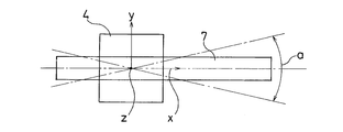
- a primary mode in which the main girder swings from side to side about the vertical axis Z located at the center, and a columnar body constituting the crane main body and the traveling device connection portion and the crane main body resulting from the occurrence of the primary mode.
- the occurrence of the twisted secondary mode can be suppressed, and therefore, the land-side traveling device can be prevented from floating from the rail.
- a laminated rubber is provided between the crane body and the traveling device, while a laminated rubber is provided between the portal tie beam and the columnar body constituting the crane body, and either Since one laminated rubber is gripped by a gripping member disposed in the traveling direction of the crane body, and the other laminated rubber is gripped by a gripping member disposed in the sea-land direction intersecting the traveling direction of the crane body, when an earthquake occurs, A primary mode in which the main girder swings from side to side about the vertical axis Z located at the center of the crane body, and a connecting portion of the crane body and the traveling device and the crane body resulting from the occurrence of the primary mode are configured. Occurrence of the secondary mode in which the columnar body is twisted can be suppressed, so that the land-side traveling device can be prevented from floating from the rail.
- FIG. 1 is an enlarged side view of a main part of a container crane according to the present invention.
- FIG. 2 is an enlarged view of part A of FIG. 3 is a cross-sectional view taken along the line BB of FIG.
- FIG. 4 is an enlarged side view of a main part of the container crane according to the present invention.
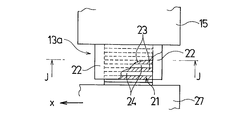
- FIG. 5 is an enlarged view of a portion C in FIG. 6 is a cross-sectional view taken along the line DD of FIG.
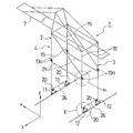
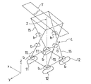
- FIG. 7 is a perspective view of a container crane according to the present invention.
- FIG. 8 is an enlarged view of a portion E in FIG.
- FIG. 11 is an enlarged view of a portion H in FIG.
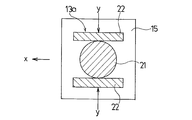
- FIG. 12 is an enlarged view of a portion I in FIG. 13 is a cross-sectional view taken along line JJ in FIG.
- FIG. 14 is a front view of a conventional container crane.
- FIG. 15 is an explanatory diagram of the primary mode.
- FIG. 16 is an explanatory diagram of the secondary mode.
- the container crane 1 is constructed of a crane body 4 from a sea limb 2 and a land leg 3, and a girder 5 and a boom 6 are mounted on the crane body 4.
- the main girder 7 is arranged in the transverse direction (hereinafter referred to as the sea-land direction) x so as to intersect the traveling direction y of the crane body 4.
- a trolley 8 traverses the main girder 7 and a container 10 on a ship or on a transport vehicle is gripped by a lifting tool 9 spread from the trolley 8.
- the traveling device 11 provided on the sea limb 2 and the traveling device 12 provided on the land leg 3 are mounted on rails (not shown) laid in the harbor and travel in the traveling direction y.
- each of the traveling devices 11 and 12 includes one main equalizer 17, two intermediate equalizers 18, and four bogies 19.
- the two intermediate equalizers 18 are provided below the main equalizer 17 so as to move back and forth with respect to the traveling direction y of the main equalizer 17.
- Two bogies 19 are provided at the bottom of each intermediate equalizer 18 so as to move back and forth with respect to the traveling direction y of the intermediate equalizer 18.
- a seismic isolation device 20 that is deformed in the traveling direction is provided between the main equalizer 17 and the intermediate equalizers 18 and 18 constituting the traveling devices 11 and 12.
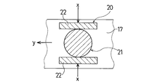
- the seismic isolation device 20 that is deformed in the traveling direction includes a laminated rubber 21 and two plate-like moment receiving portions (hereinafter referred to as gripping members) that hold or hold the laminated rubber 21 from the sea-land direction. .) 22 and 22.
- the grip members 22 are provided on the lower surface of the main equalizer 17.
- the laminated rubber 21 has a sea-land direction X of the main equalizer 17. Since the crane body 4 is gripped or sandwiched by the two gripping members 22, 22, the crane body 4 is deformed in the traveling direction y, but the deformation in the sea-land direction x is prevented by the two moment receiving portions 22, 22.
- a seismic isolation device 13 a that is deformed in the sea-land direction is installed between the crane body 4 and the traveling devices 11 and 12.
- the seismic isolation device 13a that is deformed in the sea-land direction includes a laminated rubber 21 and two flat plate-like holding members 22 and 22 that hold or hold 21 from the laminated rubber in the traveling direction y.
- the grip members 22, 22 are provided on the lower surface of the crane body 4.
- the laminated rubber 21 is gripped or sandwiched by two gripping members 22, 22 arranged in the traveling direction y of the crane body 4, so that the laminated rubber 21 is deformed in the sea-land direction X of the crane body 4.
- the deformation in the running direction y is prevented by the two gripping members 22 and 22.
- the laminated rubber 21 includes a plurality of disk-shaped rubber plates 23 and a disk-shaped metal plate 24.
- the rubber plate 23 and the metal plate 24 are not limited to a disk shape, and may be a square, hexagon, octagon, or the like.
- the seismic isolation device 13a that deforms in the sea-land direction is installed between the crane body 4 and the traveling devices 11 and 12, while the deformation is performed in the traveling direction between the main equalizer 17 and the intermediate equalizers 18 and 18, respectively.
- Seismic isolation device 2 By providing 0, the occurrence of the primary mode a in which the main girder 7 swings left and right around the vertical axis Z located at the center of the crane body 4 is suppressed when an earthquake occurs.
- the connection between the crane body 4 and the traveling devices 11 and 12 due to the generation of the primary mode a is twisted, or the secondary mode b is generated where the columnar body 15 constituting the crane body 4 is twisted. Is suppressed. Therefore, it is possible to prevent the land-side traveling device 12 from being lifted.
- a seismic isolation device 13 a that is deformed in the sea-land direction is provided between the crane body 4 and each traveling device 11, 12, while the sill beam 26 that forms the crane body 4 and the columnar shape.
- a seismic isolation device 20 that deforms in the traveling direction is provided between the bodies 15.
- the seismic isolation device 20 that is deformed in the traveling direction includes the laminated rubber 2. 1 and two plate-like moment receiving portions (hereinafter referred to as gripping members) 22 and 22 for gripping or holding the laminated rubber 21 from the transverse direction.
- the grip members 22, 22 are provided at the lower end of the columnar body 15 constituting the crane body 4.
- the laminated rubber 21 is gripped or sandwiched by two gripping members 22, 22 arranged in the sea-land direction x of the columnar body 15 constituting the crane body 4. However, the deformation in the sea-land direction X is blocked by the two gripping members 22 and 22.
- a seismic isolation device 13 a that deforms in the sea-land direction is installed between the sill beam 26 that constitutes the crane body 4 and the traveling devices 11 and 12.
- the seismic isolation device 13a that is deformed in the sea-land direction includes a laminated rubber 21 and two flat gripping members 22 and 22 that hold or sandwich the laminated rubber 21 from the traveling direction y. These moment receiving portions 22, 22 Is provided on the lower surface of the sill beam 26.
- the laminated rubber 21 is gripped or sandwiched by the two gripping members 22, 22 arranged in the traveling direction y of the crane body 4, and thus is deformed in the sea-land direction x of the crane body 4.
- the deformation in the running direction y is prevented by the two gripping members 22 and 22.
- the laminated rubber 21 includes a plurality of disk-shaped rubber plates 23 and a disk-shaped metal plate 24.
- the rubber plate 23 and the metal plate 24 are not limited to a disk shape, and may be a square, hexagon, octagon, or the like.
- the seismic isolation device 20 that deforms in the traveling direction is provided between the columnar body 15 constituting the crane body 4 and the sill beam 26, while the sea-land direction is provided between the crane body 4 and the traveling devices 11 and 12.
- Seismic isolation device 13 By providing a, the occurrence of the primary mode a in which the main girder 7 swings left and right around the vertical axis z located at the center of the crane body 4 is suppressed when an earthquake occurs.
- the connection between the crane body 4 and the traveling devices 11 and 12 due to the generation of the primary mode a is twisted, or the secondary mode b is generated where the columnar body 15 constituting the crane body 4 is twisted. Is suppressed. Therefore, it is possible to prevent the land-side traveling device 12 from being lifted.
- a portal tie beam 27 constituting the crane body 4 is provided between the crane body 4 and the traveling devices 11 and 12, while providing the seismic isolation device 20 that is deformed in the traveling direction.
- the columnar body 15 are provided with a seismic isolation device 13a that is deformed in the sea-land direction.
- the seismic isolation device 20 that is deformed in the traveling direction includes the laminated rubber 2. 1 and two plate-like moment receiving portions (hereinafter referred to as gripping members) 22 and 22 for gripping or holding the laminated rubber 21 from the sea-land direction x.
- the grip members 22, 22 are provided on the lower surface of the sill beam 26 constituting the crane body 4.
- the laminated rubber 21 has a sea-land direction x of the sill beam 26. Since it is gripped or sandwiched by the two gripping members 22, 22, it is deformed in the traveling direction y of the crane body 4, but the deformation in the sea-land direction x is prevented by the two gripping members 22, 22.
- the laminated rubber seismic isolation device 21 and two flat plate-like gripping members 22 and 22 for gripping or holding the laminated rubber 21 from the traveling direction y are configured.
- the grip members 22, 22 are provided at the lower end of the columnar object 15 constituting the crane body 4.
- the seismic isolation device 13 a that is deformed in the sea-land direction is gripped or held by two moment receiving portions 22, 22 arranged in the traveling direction y of the crane body 4. Although it is deformed in the sea-land direction X, the deformation in the traveling direction y is blocked by the two moment receiving portions 22 and 22.
- the laminated rubber 21 includes a plurality of disk-shaped rubber plates 23 and a disk-shaped metal plate 24.
- the rubber plate 23 and the metal plate 24 are not limited to a disk shape, and may be a square, hexagon, octagon, or the like.
- the primary mode a in which the main girder 7 swings left and right around the vertical axis z positioned at the center of the crane body 4 is suppressed.
- the coupling mode between the crane body 4 and the traveling devices 11 and 12 due to the generation of the primary mode a or the generation of the secondary mode b in which the columnar body 15 constituting the crane body 4 is twisted occurs. It is suppressed. Therefore, it is possible to prevent the land-side traveling device 12 from being lifted.
Landscapes
- Engineering & Computer Science (AREA)
- Mechanical Engineering (AREA)
- Control And Safety Of Cranes (AREA)
- Carriers, Traveling Bodies, And Overhead Traveling Cranes (AREA)
Abstract
コンテナクレーンにおいて、クレーン本体(4)と走行装置(11)、(12)の間に積層ゴム(21)を設ける一方、前記走行装置(11)、(12)を構成している主イコライザ(17)と中間イコライザ(18)の間に積層ゴム(21)を設け、かつ、何れか一方の積層ゴム(21)をクレーン本体(4)の走行方向yに配した把持部材(22)、(22)によって把持し、他方の積層ゴム(21)をクレーン本体(4)の走行方向yと交差する海陸方向xに配した把持部材(22)、(22)によって把持する。
Description
本発明は、コンテナクレーン、更に詳しくは、走行方向に変形する免
震装置を具備したコンテナクレーンに関するものである。
震装置を具備したコンテナクレーンに関するものである。
一般に、コンテナクレーン1は、図14に示すように、海脚2と陸脚
3よりクレーン本体4を構築し、このクレーン本体4上にガーダ5及び
ブーム6より成る主桁7をクレーン本体4の走行方向yと交差するよう
に横行方向(以下、海陸方向と称する。)xに向けて設置している。そ
して、主桁7上をトロリー8が横行する一方、トロリー8から吊るした
吊り具(スプレッダ)9によって船上あるいは搬送車上のコンテナ10
を把持するようになっている。海脚2に設けた走行装置11と陸脚3に
設けた走行装置12は、港湾に敷設されたレール(図示せず)に乗り、
走行方向yに移動できるようになっている。
3よりクレーン本体4を構築し、このクレーン本体4上にガーダ5及び
ブーム6より成る主桁7をクレーン本体4の走行方向yと交差するよう
に横行方向(以下、海陸方向と称する。)xに向けて設置している。そ
して、主桁7上をトロリー8が横行する一方、トロリー8から吊るした
吊り具(スプレッダ)9によって船上あるいは搬送車上のコンテナ10
を把持するようになっている。海脚2に設けた走行装置11と陸脚3に
設けた走行装置12は、港湾に敷設されたレール(図示せず)に乗り、
走行方向yに移動できるようになっている。
従来のコンテナクレーン1は、横行方向に変形する免震装置13を具
備し、走行方向の揺れについては走行装置11,12に設けられている
車輪14とレールの滑りで吸収するようになっている。
備し、走行方向の揺れについては走行装置11,12に設けられている
車輪14とレールの滑りで吸収するようになっている。
しかしながら、改正された港湾法では、設定されている地震強度が高
く、車輪とレール間の摩擦力でも浮き上がり力が発生するケースも出て
きている。
く、車輪とレール間の摩擦力でも浮き上がり力が発生するケースも出て
きている。
即ち、地震が発生すると、図15に示すように、主桁7がクレーン本
体4の中心に位置する鉛直軸zを軸にして左右に揺れる1次モードaが
発生し、同時に、図16に示すように、クレーン本体4と走行装置11
,12の連結部及びクレーン本体4を形成している柱状体15が捩じれ
る2次モードbが発生する。更に、主桁7のブーム先端が海側に大きく
突き出していることから陸側の走行装置12がレールから浮き上がるこ
とがある。そして、陸側の走行装置12が脱線することもある。
体4の中心に位置する鉛直軸zを軸にして左右に揺れる1次モードaが
発生し、同時に、図16に示すように、クレーン本体4と走行装置11
,12の連結部及びクレーン本体4を形成している柱状体15が捩じれ
る2次モードbが発生する。更に、主桁7のブーム先端が海側に大きく
突き出していることから陸側の走行装置12がレールから浮き上がるこ
とがある。そして、陸側の走行装置12が脱線することもある。
なお、複数枚のゴム板を金属板を介して積層した積層ゴムと、この積
層ゴムを上下方向から狭持するゴム狭持部材からなる積層ゴム構造を具
備した走行クレーンの耐震構造が提案されているが(例えば、特許文献
1参照。)、このような構造では、走行方向、或いは、海陸方向の免震
力を発揮させることが難しい。
層ゴムを上下方向から狭持するゴム狭持部材からなる積層ゴム構造を具
備した走行クレーンの耐震構造が提案されているが(例えば、特許文献
1参照。)、このような構造では、走行方向、或いは、海陸方向の免震
力を発揮させることが難しい。
本発明は、上記のような問題を解消するために発明したものであり、
走行方向、或いは、海陸方向の免震力を発揮することができるコンテナ
クレーンを提供することにある。
走行方向、或いは、海陸方向の免震力を発揮することができるコンテナ
クレーンを提供することにある。
本願の請求項1に係るコンテナクレーンは、海脚と陸脚より成るクレ
ーン本体に、該クレーン本体の走行方向と交差する方向に主桁を設置し
、該主桁上を横行するトロリーから吊るした吊り具によって船上又は搬
送車上のコンテナを把持し、かつ、海脚及び陸脚に設けた走行装置が港
湾に敷設したレール上を走行するコンテナクレーンにおいて、前記クレ
ーン本体と走行装置の間に積層ゴムを設ける一方、前記走行装置を構成
している主イコライザと中間イコライザの間に積層ゴムを設け、かつ、
何れか一方の積層ゴムをクレーン本体の走行方向に配した把持部材によ
って把持し、他方の積層ゴムをクレーン本体の走行方向と交差する海陸
方向に配した把持部材によって把持することに特徴がある。
ーン本体に、該クレーン本体の走行方向と交差する方向に主桁を設置し
、該主桁上を横行するトロリーから吊るした吊り具によって船上又は搬
送車上のコンテナを把持し、かつ、海脚及び陸脚に設けた走行装置が港
湾に敷設したレール上を走行するコンテナクレーンにおいて、前記クレ
ーン本体と走行装置の間に積層ゴムを設ける一方、前記走行装置を構成
している主イコライザと中間イコライザの間に積層ゴムを設け、かつ、
何れか一方の積層ゴムをクレーン本体の走行方向に配した把持部材によ
って把持し、他方の積層ゴムをクレーン本体の走行方向と交差する海陸
方向に配した把持部材によって把持することに特徴がある。
本願の請求項2に係るコンテナクレーンは、海脚と陸脚より成るクレ
ーン本体に、該クレーン本体の走行方向と交差する方向に主桁を設置し
、該主桁上を横行するトロリーから吊るした吊り具によって船上又は搬
送車上のコンテナを把持し、かつ、海脚及び陸脚に設けた走行装置が港
湾に敷設したレール上を走行するコンテナクレーンにおいて、前記クレ
ーン本体と走行装置の間に積層ゴムを設ける一方、クレーン本体を構成
しているシルビームと柱状体の間に積層ゴムを設け、かつ、何れか一方
の積層ゴムをクレーン本体の走行方向に配した把持部材によって把持し
、他方の積層ゴムをクレーン本体の走行方向と交差する海陸方向に配し
た把持部材によって把持することに特徴がある。
ーン本体に、該クレーン本体の走行方向と交差する方向に主桁を設置し
、該主桁上を横行するトロリーから吊るした吊り具によって船上又は搬
送車上のコンテナを把持し、かつ、海脚及び陸脚に設けた走行装置が港
湾に敷設したレール上を走行するコンテナクレーンにおいて、前記クレ
ーン本体と走行装置の間に積層ゴムを設ける一方、クレーン本体を構成
しているシルビームと柱状体の間に積層ゴムを設け、かつ、何れか一方
の積層ゴムをクレーン本体の走行方向に配した把持部材によって把持し
、他方の積層ゴムをクレーン本体の走行方向と交差する海陸方向に配し
た把持部材によって把持することに特徴がある。
本願の請求項3に係るコンテナクレーンは、海脚と陸脚より成るクレ
ーン本体に、該クレーン本体の走行方向と交差する方向に主桁を設置し
、該主桁上を横行するトロリーから吊るした吊り具によって船上又は搬
送車上のコンテナを把持し、かつ、海脚及び陸脚に設けた走行装置が港
湾に敷設したレール上を走行するコンテナクレーンにおいて、前記クレ
ーン本体と走行装置の間に積層ゴムを設ける一方、前記クレーン本体を
構成しているポータルタイビームと柱状体の間に積層ゴムを設け、かつ
、何れか一方の積層ゴムをクレーン本体の走行方向に配した把持部材に
よって把持し、他方の積層ゴムをクレーン本体の走行方向と交差する海
陸方向に配した把持部材によって把持することに特徴がある。
ーン本体に、該クレーン本体の走行方向と交差する方向に主桁を設置し
、該主桁上を横行するトロリーから吊るした吊り具によって船上又は搬
送車上のコンテナを把持し、かつ、海脚及び陸脚に設けた走行装置が港
湾に敷設したレール上を走行するコンテナクレーンにおいて、前記クレ
ーン本体と走行装置の間に積層ゴムを設ける一方、前記クレーン本体を
構成しているポータルタイビームと柱状体の間に積層ゴムを設け、かつ
、何れか一方の積層ゴムをクレーン本体の走行方向に配した把持部材に
よって把持し、他方の積層ゴムをクレーン本体の走行方向と交差する海
陸方向に配した把持部材によって把持することに特徴がある。
本願の請求項1に係る発明は、クレーン本体と走行装置の間に積層ゴ
ムを設ける一方、前記走行装置を構成している主イコライザと中間イコ
ライザの間に積層ゴムを設け、かつ、何れか一方の積層ゴムをクレーン
本体の走行方向に配した把持部材によって把持し、他方の積層ゴムをク
レーン本体の走行方向と交差する海陸方向に配した把持部材によって把
持するので、地震が発生した時、クレーン本体の中心に位置する鉛直軸
Zを軸にして主桁が左右に揺れる1次モードと、この1次モードの発生
に起因するクレーン本体と走行装置の連結部及びクレーン本体を構成し
ている柱状体が捩じれる2次モードの発生を抑制することができ、以て
、陸側の走行装置がレールから浮き上がるのを回避することができる。
ムを設ける一方、前記走行装置を構成している主イコライザと中間イコ
ライザの間に積層ゴムを設け、かつ、何れか一方の積層ゴムをクレーン
本体の走行方向に配した把持部材によって把持し、他方の積層ゴムをク
レーン本体の走行方向と交差する海陸方向に配した把持部材によって把
持するので、地震が発生した時、クレーン本体の中心に位置する鉛直軸
Zを軸にして主桁が左右に揺れる1次モードと、この1次モードの発生
に起因するクレーン本体と走行装置の連結部及びクレーン本体を構成し
ている柱状体が捩じれる2次モードの発生を抑制することができ、以て
、陸側の走行装置がレールから浮き上がるのを回避することができる。
本願の請求項2に係る発明は、クレーン本体と走行装置の間に積層ゴ
ムを設ける一方、クレーン本体を構成しているシルビームと柱状体の間
に積層ゴムを設け、かつ、何れか一方の積層ゴムをクレーン本体の走行
方向に配した把持部材によって把持し、他方の積層ゴムをクレーン本体
の走行方向と交差する海陸方向に配した把持部材によって把持するので
、地震が発生した時、クレーン本体の中心に位置する鉛直軸Zを軸にし
て主桁が左右に揺れる1次モードと、この1次モードの発生に起因する
クレーン本体と走行装置の連結部及びクレーン本体を構成している柱状
体が捩じれる2次モードの発生を抑制することができ、以て、陸側の走
行装置がレールから浮き上がるのを回避することができる。
ムを設ける一方、クレーン本体を構成しているシルビームと柱状体の間
に積層ゴムを設け、かつ、何れか一方の積層ゴムをクレーン本体の走行
方向に配した把持部材によって把持し、他方の積層ゴムをクレーン本体
の走行方向と交差する海陸方向に配した把持部材によって把持するので
、地震が発生した時、クレーン本体の中心に位置する鉛直軸Zを軸にし
て主桁が左右に揺れる1次モードと、この1次モードの発生に起因する
クレーン本体と走行装置の連結部及びクレーン本体を構成している柱状
体が捩じれる2次モードの発生を抑制することができ、以て、陸側の走
行装置がレールから浮き上がるのを回避することができる。
本願の請求項3に係る発明は、クレーン本体と走行装置の間に積層ゴ
ムを設ける一方、前記クレーン本体を構成しているポータルタイビーム
と柱状体の間に積層ゴムを設け、かつ、何れか一方の積層ゴムをクレー
ン本体の走行方向に配した把持部材によって把持し、他方の積層ゴムを
クレーン本体の走行方向と交差する海陸方向に配した把持部材によって
把持するので、地震が発生した時、クレーン本体の中心に位置する鉛直
軸Zを軸にして主桁が左右に揺れる1次モードと、この1次モードの発
生に起因するクレーン本体と走行装置の連結部及びクレーン本体を構成
している柱状体が捩じれる2次モードの発生を抑制することができ、以
て、陸側の走行装置がレールから浮き上がるのを回避することができる
。
ムを設ける一方、前記クレーン本体を構成しているポータルタイビーム
と柱状体の間に積層ゴムを設け、かつ、何れか一方の積層ゴムをクレー
ン本体の走行方向に配した把持部材によって把持し、他方の積層ゴムを
クレーン本体の走行方向と交差する海陸方向に配した把持部材によって
把持するので、地震が発生した時、クレーン本体の中心に位置する鉛直
軸Zを軸にして主桁が左右に揺れる1次モードと、この1次モードの発
生に起因するクレーン本体と走行装置の連結部及びクレーン本体を構成
している柱状体が捩じれる2次モードの発生を抑制することができ、以
て、陸側の走行装置がレールから浮き上がるのを回避することができる
。
(1)実施形態1
先ず、本発明の第1の実施形態について説明する。
先ず、本発明の第1の実施形態について説明する。
図14に示すように、コンテナクレーン1は、海脚2と陸脚3よりク
レーン本体4を構築し、このクレーン本体4上にガーダ5及びブーム6
より成る主桁7をクレーン本体4の走行方向yと交差するように横行方
向(以下、海陸方向と称する。)xに設置している。そして、主桁7上
をトロリー8が横行すると共に、トロリー8から吊るした吊り具(スプ
レッダ)9によって船上あるいは搬送車上のコンテナ10を把持するよ
うになっている。海脚2に設けた走行装置11と陸脚3に設けた走行装
置12は、港湾に敷設されたレール(図示せず)に搭載され、走行方向
yに走行するようになっている。
レーン本体4を構築し、このクレーン本体4上にガーダ5及びブーム6
より成る主桁7をクレーン本体4の走行方向yと交差するように横行方
向(以下、海陸方向と称する。)xに設置している。そして、主桁7上
をトロリー8が横行すると共に、トロリー8から吊るした吊り具(スプ
レッダ)9によって船上あるいは搬送車上のコンテナ10を把持するよ
うになっている。海脚2に設けた走行装置11と陸脚3に設けた走行装
置12は、港湾に敷設されたレール(図示せず)に搭載され、走行方向
yに走行するようになっている。
図1に示すように、走行装置11,12は、それぞれ、1基の主イコ
ライザ17と、2基の中間イコライザ18と、4基のボギー19より構
成されている。2基の中間イコライザ18は、主イコライザ17の走行
方向yに対して前後するように主イコライザ17の下部に設けられてい
る。ボギー19は、中間イコライザ18の走行方向yに対して前後する
ように各中間イコライザ18の下部に2基ずつ設けられている。
ライザ17と、2基の中間イコライザ18と、4基のボギー19より構
成されている。2基の中間イコライザ18は、主イコライザ17の走行
方向yに対して前後するように主イコライザ17の下部に設けられてい
る。ボギー19は、中間イコライザ18の走行方向yに対して前後する
ように各中間イコライザ18の下部に2基ずつ設けられている。
この実施形態では、各走行装置11,12を構成している主イコライ
ザ17と各中間イコライザ18,18の間にそれぞれ走行方向に変形す
る免震装置20を設けている。走行方向に変形する免震装置20は、図
2に示すように、積層ゴム21と、積層ゴム21を海陸方向から把持又
は狭持する平板状の二つのモーメント受け部(以下、把持部材と称する
。)22,22より構成されている。この把持部材22,22は、主イ
コライザ17の下面に設けられている。
ザ17と各中間イコライザ18,18の間にそれぞれ走行方向に変形す
る免震装置20を設けている。走行方向に変形する免震装置20は、図
2に示すように、積層ゴム21と、積層ゴム21を海陸方向から把持又
は狭持する平板状の二つのモーメント受け部(以下、把持部材と称する
。)22,22より構成されている。この把持部材22,22は、主イ
コライザ17の下面に設けられている。
積層ゴム21は、図3に示すように、主イコライザ17の海陸方向X
に配置した二つの把持部材22,22によって把持又は狭持されるため
、クレーン本体4の走行方向yに変形するが、海陸方向xの変形は二つ
のモーメント受け部22,22によって阻止される。
に配置した二つの把持部材22,22によって把持又は狭持されるため
、クレーン本体4の走行方向yに変形するが、海陸方向xの変形は二つ
のモーメント受け部22,22によって阻止される。
他方、図1に示すように、クレーン本体4と各走行装置11,12の
間に海陸方向に変形する免震装置13aを設置している。海陸方向に変
形する免震装置13aは、積層ゴム21と、積層ゴムから21を走行方
向yから把持又は狭持する平板状の二つの把持部材22,22より構成
されている。この把持部材22,22は、クレーン本体4の下面に設け
られている。
間に海陸方向に変形する免震装置13aを設置している。海陸方向に変
形する免震装置13aは、積層ゴム21と、積層ゴムから21を走行方
向yから把持又は狭持する平板状の二つの把持部材22,22より構成
されている。この把持部材22,22は、クレーン本体4の下面に設け
られている。
積層ゴム21は、図1に示すように、クレーン本体4の走行方向yに
配置した二つの把持部材22,22によって把持又は狭持されているた
め、クレーン本体4の海陸方向Xに変形するが、走行方向yの変形は二
つの把持部材22,22によって阻止される。
配置した二つの把持部材22,22によって把持又は狭持されているた
め、クレーン本体4の海陸方向Xに変形するが、走行方向yの変形は二
つの把持部材22,22によって阻止される。
積層ゴム21は、円板状の複数枚のゴム板23を円板状の金属板24
を介して積層したものであるが、ゴム板23や金属板24は、円板状に
限らず、例えば、正方形、六角形、八角形などでも支障がない。
を介して積層したものであるが、ゴム板23や金属板24は、円板状に
限らず、例えば、正方形、六角形、八角形などでも支障がない。
上記のように、クレーン本体4と各走行装置11,12の間に海陸方
向に変形する免震装置13aを設置する一方、主イコライザ17と各中
間イコライザ18,18の間にそれぞれ走行方向に変形する免震装置2
0を設けることにより、地震発生時に、クレーン本体4の中心に位置す
る鉛直軸Zを軸にして主桁7が左右に揺れる1次モードaの発生が抑制
される。同時に、1次モードaの発生に起因するクレーン本体4と走行
装置11,12の間の連結部の捩じれ、あるいは、クレーン本体4を構
成している柱状体15が捩じれる2次モードbの発生が抑制される。そ
のため、陸側の走行装置12の浮き上がりを防止することができる。
向に変形する免震装置13aを設置する一方、主イコライザ17と各中
間イコライザ18,18の間にそれぞれ走行方向に変形する免震装置2
0を設けることにより、地震発生時に、クレーン本体4の中心に位置す
る鉛直軸Zを軸にして主桁7が左右に揺れる1次モードaの発生が抑制
される。同時に、1次モードaの発生に起因するクレーン本体4と走行
装置11,12の間の連結部の捩じれ、あるいは、クレーン本体4を構
成している柱状体15が捩じれる2次モードbの発生が抑制される。そ
のため、陸側の走行装置12の浮き上がりを防止することができる。
また、海陸方向に変形する免震装置13aと走行方向に変形する免震
装置20を互いに入れ換えても同様の効果を得ることができる。
装置20を互いに入れ換えても同様の効果を得ることができる。
(2)実施形態2
次に、本発明の第2の実施形態について説明するが、第1の実施形態
の部材と同じ部材に同じ符号を付けて詳しい説明を省略する。
次に、本発明の第2の実施形態について説明するが、第1の実施形態
の部材と同じ部材に同じ符号を付けて詳しい説明を省略する。
図4に示すように、この実施形態では、クレーン本体4と各走行装置
11,12の間に海陸方向に変形する免震装置13aを設ける一方、ク
レーン本体4を構成しているシルビーム26と柱状体15の間に走行方
向に変形する免震装置20を設けている。
11,12の間に海陸方向に変形する免震装置13aを設ける一方、ク
レーン本体4を構成しているシルビーム26と柱状体15の間に走行方
向に変形する免震装置20を設けている。
走行方向に変形する免震装置20は、図5に示すように、積層ゴム2
1と、積層ゴム21を横行方向から把持又は狭持する平板状の二つのモ
ーメント受け部(以下、把持部材と称する。)22,22より構成され
ている。この把持部材22,22は、クレーン本体4を構成している柱
状体15の下端部に設けられている。
1と、積層ゴム21を横行方向から把持又は狭持する平板状の二つのモ
ーメント受け部(以下、把持部材と称する。)22,22より構成され
ている。この把持部材22,22は、クレーン本体4を構成している柱
状体15の下端部に設けられている。
積層ゴム21は、図6に示すように、クレーン本体4を構成している
柱状体15の海陸方向xに配置した二つの把持部材22,22によって
把持又は狭持されているため、クレーン本体4の走行方向yに変形する
が、海陸方向Xの変形は二つの把持部材22,22によって阻止される
。
柱状体15の海陸方向xに配置した二つの把持部材22,22によって
把持又は狭持されているため、クレーン本体4の走行方向yに変形する
が、海陸方向Xの変形は二つの把持部材22,22によって阻止される
。
他方、図4に示すように、クレーン本体4を構成しているシルビーム
26と走行装置11,12の間に海陸方向に変形する免震装置13aを
設置している。海陸方向に変形する免震装置13aは、積層ゴム21と
、積層ゴム21を走行方向yから把持又は狭持する平板状の二つの把持
部材22,22より構成されている。このモーメント受け部22,22
は、シルビーム26の下面に設けられている。
26と走行装置11,12の間に海陸方向に変形する免震装置13aを
設置している。海陸方向に変形する免震装置13aは、積層ゴム21と
、積層ゴム21を走行方向yから把持又は狭持する平板状の二つの把持
部材22,22より構成されている。このモーメント受け部22,22
は、シルビーム26の下面に設けられている。
積層ゴム21は、図4に示すように、クレーン本体4の走行方向yに
配置した二つの把持部材22,22によって把持又は狭持されているた
め、クレーン本体4の海陸方向xに変形するが、走行方向yの変形は二
つの把持部材22,22によって阻止される。
配置した二つの把持部材22,22によって把持又は狭持されているた
め、クレーン本体4の海陸方向xに変形するが、走行方向yの変形は二
つの把持部材22,22によって阻止される。
積層ゴム21は、円板状の複数枚のゴム板23を円板状の金属板24
を介して積層したものであるが、ゴム板23や金属板24は、円板状に
限らず、例えば、正方形、六角形、八角形などでも支障がない。
を介して積層したものであるが、ゴム板23や金属板24は、円板状に
限らず、例えば、正方形、六角形、八角形などでも支障がない。
上記のように、クレーン本体4を構成している柱状体15とシルビー
ム26の間に走行方向に変形する免震装置20を設ける一方、クレーン
本体4と各走行装置11,12の間に海陸方向に変形する免震装置13
aを設けたことにより、地震発生時に、クレーン本体4の中心に位置す
る鉛直軸zを軸にして主桁7が左右に揺れる1次モードaの発生が抑制
される。同時に、1次モードaの発生に起因するクレーン本体4と走行
装置11,12の間の連結部の捩じれ、あるいは、クレーン本体4を構
成している柱状体15が捩じれる2次モードbの発生が抑制される。そ
のため、陸側の走行装置12の浮き上がりを防止することができる。
ム26の間に走行方向に変形する免震装置20を設ける一方、クレーン
本体4と各走行装置11,12の間に海陸方向に変形する免震装置13
aを設けたことにより、地震発生時に、クレーン本体4の中心に位置す
る鉛直軸zを軸にして主桁7が左右に揺れる1次モードaの発生が抑制
される。同時に、1次モードaの発生に起因するクレーン本体4と走行
装置11,12の間の連結部の捩じれ、あるいは、クレーン本体4を構
成している柱状体15が捩じれる2次モードbの発生が抑制される。そ
のため、陸側の走行装置12の浮き上がりを防止することができる。
また、海陸方向に変形する免震装置13aと走行方向に変形する免震
装置20を互いに入れ換えても同様の効果を得ることができる。
装置20を互いに入れ換えても同様の効果を得ることができる。
(3)実施形態3
次に、本発明の第3の実施形態について説明するが、第1の実施形態
の部材と同じ部材に同じ符号を付けて詳しい説明を省略する。
次に、本発明の第3の実施形態について説明するが、第1の実施形態
の部材と同じ部材に同じ符号を付けて詳しい説明を省略する。
この実施形態では、図7に示すように、クレーン本体4と各走行装置
11,12の間に走行方向に変形する免震装置20を設ける一方、クレ
ーン本体4を構成しているポータルタイビーム27と柱状体15の間に
海陸方向に変形する免震装置13aを設けている。
11,12の間に走行方向に変形する免震装置20を設ける一方、クレ
ーン本体4を構成しているポータルタイビーム27と柱状体15の間に
海陸方向に変形する免震装置13aを設けている。
走行方向に変形する免震装置20は、図9に示すように、積層ゴム2
1と、積層ゴム21を海陸方向xから把持又は狭持する平板状の二つの
モーメント受け部(以下、把持部材と称する。)22,22より構成さ
れている。この把持部材22,22は、クレーン本体4を構成している
シルビーム26の下面に設けられている。
1と、積層ゴム21を海陸方向xから把持又は狭持する平板状の二つの
モーメント受け部(以下、把持部材と称する。)22,22より構成さ
れている。この把持部材22,22は、クレーン本体4を構成している
シルビーム26の下面に設けられている。
積層ゴム21は、図10に示すように、シルビーム26の海陸方向x
に配置した二つの把持部材22,22によって把持又は狭持されている
ため、クレーン本体4の走行方向yに変形するが、海陸方向xの変形は
二つの把持部材22,22によって阻止される。
に配置した二つの把持部材22,22によって把持又は狭持されている
ため、クレーン本体4の走行方向yに変形するが、海陸方向xの変形は
二つの把持部材22,22によって阻止される。
他方、海陸方向に変形する免震装置13aは、図12に示すように、
積層ゴム免震装置21と、積層ゴム21を走行方向yから把持又は狭持
する平板状の二つの把持部材22,22より構成されている。この把持
部材22,22は、クレーン本体4を構成している柱状物15の下端部
に設けられている。
積層ゴム免震装置21と、積層ゴム21を走行方向yから把持又は狭持
する平板状の二つの把持部材22,22より構成されている。この把持
部材22,22は、クレーン本体4を構成している柱状物15の下端部
に設けられている。
海陸方向に変形する免震装置13aは、図13に示すように、クレー
ン本体4の走行方向yに配置した二つのモーメント受け部22,22に
よって把持又は狭持されているため、クレーン本体4の海陸方向Xに変
形するが、走行方向yの変形は二つのモーメント受け部22,22によ
って阻止される。
ン本体4の走行方向yに配置した二つのモーメント受け部22,22に
よって把持又は狭持されているため、クレーン本体4の海陸方向Xに変
形するが、走行方向yの変形は二つのモーメント受け部22,22によ
って阻止される。
積層ゴム21は、円板状の複数枚のゴム板23を円板状の金属板24
を介して積層したものであるが、ゴム板23や金属板24は、円板状に
限らず、例えば、正方形、六角形、八角形などでも支障がない。
を介して積層したものであるが、ゴム板23や金属板24は、円板状に
限らず、例えば、正方形、六角形、八角形などでも支障がない。
上記の構成により、地震発生時に、クレーン本体4の中心に位置する
鉛直軸zを軸にして主桁7が左右に揺れる1次モードaの発生が抑制さ
れる。同時に、1次モードaの発生に起因するクレーン本体4と走行装
置11,12間の連結部の捩じれ、あるいは、クレーン本体4を構成し
ている柱状体15が捩じれる2次モードbの発生が抑制される。そのた
め、陸側の走行装置12の浮き上がりを防止することができる。
鉛直軸zを軸にして主桁7が左右に揺れる1次モードaの発生が抑制さ
れる。同時に、1次モードaの発生に起因するクレーン本体4と走行装
置11,12間の連結部の捩じれ、あるいは、クレーン本体4を構成し
ている柱状体15が捩じれる2次モードbの発生が抑制される。そのた
め、陸側の走行装置12の浮き上がりを防止することができる。
また、海陸方向に変形する免震装置13aと走行方向に変形する免震
装置20を互いに入れ換えても同様の効果を得ることができる。
装置20を互いに入れ換えても同様の効果を得ることができる。
2 海脚
3 陸脚
4 クレーン本体
5 ガーダ
6 ブーム
7 主桁
8 トロリー
9 吊り具
10 コンテナ
11,12 走行装置
17 主イコライザ
18 中間イコライザ
20 免震装置
21 積層ゴム
22 モーメント受け部
x 横行方向
y 走行方向
3 陸脚
4 クレーン本体
5 ガーダ
6 ブーム
7 主桁
8 トロリー
9 吊り具
10 コンテナ
11,12 走行装置
17 主イコライザ
18 中間イコライザ
20 免震装置
21 積層ゴム
22 モーメント受け部
x 横行方向
y 走行方向
Claims (3)
- 海脚と陸脚より成るクレーン本体に、該クレーン本体の走行方向と交差する方向に主桁を設置し、該主桁上を横行するトロリーから吊るした吊り具によって船上又は搬送車上のコンテナを把持し、かつ、海脚及び陸脚に設けた走行装置が港湾に敷設したレール上を走行するコンテナクレーンにおいて、前記クレーン本体と走行装置の間に積層ゴムを設ける一方、前記走行装置を構成している主イコライザと中間イコライザの間に積層ゴムを設け、かつ、何れか一方の積層ゴムをクレーン本体の走行方向に配した把持部材によって把持し、他方の積層ゴムをクレーン本体の走行方向と交差する海陸方向に配した把持部材によって把持することを特徴とするコンテナクレーン。
- 海脚と陸脚より成るクレーン本体に、該クレーン本体の走行方向と交差する方向に主桁を設置し、該主桁上を横行するトロリーから吊るした吊り具によって船上又は搬送車上のコンテナを把持し、かつ、海脚及び陸脚に設けた走行装置が港湾に敷設したレール上を走行するコンテナクレーンにおいて、前記クレーン本体と走行装置の間に積層ゴムを設ける一方、クレーン本体を構成しているシルビームと柱状体の間に積層ゴムを設け、かつ、何れか一方の積層ゴムをクレーン本体の走行方向に配した把持部材によって把持し、他方の積層ゴムをクレーン本体の走行方向と交差する海陸方向に配した把持部材によって把持することを特徴とするコンテナクレーン。
- 海脚と陸脚より成るクレーン本体に、該クレーン本体の走行方向と交差する方向に主桁を設置し、該主桁上を横行するトロリーから吊るした吊り具によって船上又は搬送車上のコンテナを把持し、かつ、海脚及び陸脚に設けた走行装置が港湾に敷設したレール上を走行するコンテナクレーンにおいて、前記クレーン本体と走行装置の間に積層ゴムを設ける一方、前記クレーン本体を構成しているポータルタイビームと柱状体の間に積層ゴムを設け、かつ、何れか一方の積層ゴムをクレーン本体の走行方向に配した把持部材によって把持し、他方の積層ゴムをクレーン本体の走行方向と交差する海陸方向に配した把持部材によって把持することを特徴とするコンテナクレーン。
Applications Claiming Priority (2)
| Application Number | Priority Date | Filing Date | Title |
|---|---|---|---|
| JP2011074530A JP5744595B2 (ja) | 2011-03-30 | 2011-03-30 | コンテナクレーン |
| JP2011-074530 | 2011-03-30 |
Publications (1)
| Publication Number | Publication Date |
|---|---|
| WO2012133424A1 true WO2012133424A1 (ja) | 2012-10-04 |
Family
ID=46931140
Family Applications (1)
| Application Number | Title | Priority Date | Filing Date |
|---|---|---|---|
| PCT/JP2012/057959 Ceased WO2012133424A1 (ja) | 2011-03-30 | 2012-03-27 | コンテナクレーン |
Country Status (2)
| Country | Link |
|---|---|
| JP (1) | JP5744595B2 (ja) |
| WO (1) | WO2012133424A1 (ja) |
Cited By (1)
| Publication number | Priority date | Publication date | Assignee | Title |
|---|---|---|---|---|
| CN110307452A (zh) * | 2018-12-29 | 2019-10-08 | 常熟市奥斯维车辆科技有限公司 | 一种四联六自由度精调机构 |
Citations (3)
| Publication number | Priority date | Publication date | Assignee | Title |
|---|---|---|---|---|
| JP2001226068A (ja) * | 2000-02-17 | 2001-08-21 | Ishikawajima Harima Heavy Ind Co Ltd | 走行クレーンの免震構造 |
| JP2002302377A (ja) * | 2001-04-10 | 2002-10-18 | Mitsubishi Heavy Ind Ltd | 免震型クレーン |
| JP2007284230A (ja) * | 2006-04-19 | 2007-11-01 | Jfe Engineering Kk | クレーン及びその免震方法 |
-
2011
- 2011-03-30 JP JP2011074530A patent/JP5744595B2/ja active Active
-
2012
- 2012-03-27 WO PCT/JP2012/057959 patent/WO2012133424A1/ja not_active Ceased
Patent Citations (3)
| Publication number | Priority date | Publication date | Assignee | Title |
|---|---|---|---|---|
| JP2001226068A (ja) * | 2000-02-17 | 2001-08-21 | Ishikawajima Harima Heavy Ind Co Ltd | 走行クレーンの免震構造 |
| JP2002302377A (ja) * | 2001-04-10 | 2002-10-18 | Mitsubishi Heavy Ind Ltd | 免震型クレーン |
| JP2007284230A (ja) * | 2006-04-19 | 2007-11-01 | Jfe Engineering Kk | クレーン及びその免震方法 |
Cited By (2)
| Publication number | Priority date | Publication date | Assignee | Title |
|---|---|---|---|---|
| CN110307452A (zh) * | 2018-12-29 | 2019-10-08 | 常熟市奥斯维车辆科技有限公司 | 一种四联六自由度精调机构 |
| CN110307452B (zh) * | 2018-12-29 | 2024-03-29 | 常熟市奥斯维车辆科技有限公司 | 一种四联六自由度精调机构 |
Also Published As
| Publication number | Publication date |
|---|---|
| JP2012206839A (ja) | 2012-10-25 |
| JP5744595B2 (ja) | 2015-07-08 |
Similar Documents
| Publication | Publication Date | Title |
|---|---|---|
| US9663121B2 (en) | Railcar bogie and railcar including same | |
| KR20150034278A (ko) | 오버헤드 크레인 및 적어도 두 개의 오버헤드 크레인의 어셈블리 | |
| JP5744595B2 (ja) | コンテナクレーン | |
| CN103723247B (zh) | 单点浮筒装船运输过程中的绑扎式固定装置 | |
| TW201524884A (zh) | 門型起重機的配置結構 | |
| CN110733530B (zh) | 一种用于轮对输送的智能转轨装置 | |
| JP5479863B2 (ja) | 岸壁クレーン | |
| JP2012211012A (ja) | 橋型クレーン | |
| CN201132254Y (zh) | 大型箱形梁的翻转装置 | |
| CN203898571U (zh) | 伤病员担架减震系统 | |
| CN103193148B (zh) | 铁路机车顶盖吊装构件及吊装架 | |
| CN103350953B (zh) | 用于起重运输车的升降装置 | |
| CN103303805B (zh) | 一种用于集装箱装卸的双层岸桥 | |
| CN104649139A (zh) | 船用龙门起重机行走装置 | |
| CN105877931A (zh) | 一种四自由度并联减振担架平台 | |
| CN104085401B (zh) | 一种轨道车辆牵引变压器悬挂装置以及轨道车辆 | |
| CN104195942A (zh) | 桥梁底面检修结构 | |
| CN205367484U (zh) | 防脱型起重机悬挂端梁 | |
| CN204022295U (zh) | 门式起重机交叉互通轨道接头 | |
| CN103663159A (zh) | 一种具有分载结构的起重机 | |
| CN205239505U (zh) | 18米钢轨普通平车运输专用座架 | |
| CN104085400A (zh) | 管道式列车运行防护装置 | |
| CN203865369U (zh) | 一种房屋工字型钢构搬运装置 | |
| JP6266552B2 (ja) | 燃料取扱装置及びその運転方法 | |
| CN206813001U (zh) | 摆动式索道支撑装置 |
Legal Events
| Date | Code | Title | Description |
|---|---|---|---|
| 121 | Ep: the epo has been informed by wipo that ep was designated in this application |
Ref document number: 12763888 Country of ref document: EP Kind code of ref document: A1 |
|
| NENP | Non-entry into the national phase |
Ref country code: DE |
|
| 122 | Ep: pct application non-entry in european phase |
Ref document number: 12763888 Country of ref document: EP Kind code of ref document: A1 |