WO2012133368A1 - 積層シートおよびそれを用いた太陽電池 - Google Patents
積層シートおよびそれを用いた太陽電池 Download PDFInfo
- Publication number
- WO2012133368A1 WO2012133368A1 PCT/JP2012/057861 JP2012057861W WO2012133368A1 WO 2012133368 A1 WO2012133368 A1 WO 2012133368A1 JP 2012057861 W JP2012057861 W JP 2012057861W WO 2012133368 A1 WO2012133368 A1 WO 2012133368A1
- Authority
- WO
- WIPO (PCT)
- Prior art keywords
- layer
- laminated sheet
- sheet
- mass
- solar cell
- Prior art date
- Legal status (The legal status is an assumption and is not a legal conclusion. Google has not performed a legal analysis and makes no representation as to the accuracy of the status listed.)
- Ceased
Links
Images

Classifications
-
- B—PERFORMING OPERATIONS; TRANSPORTING
- B32—LAYERED PRODUCTS
- B32B—LAYERED PRODUCTS, i.e. PRODUCTS BUILT-UP OF STRATA OF FLAT OR NON-FLAT, e.g. CELLULAR OR HONEYCOMB, FORM
- B32B27/00—Layered products comprising a layer of synthetic resin
- B32B27/36—Layered products comprising a layer of synthetic resin comprising polyesters
- B32B27/365—Layered products comprising a layer of synthetic resin comprising polyesters comprising polycarbonates
-
- B—PERFORMING OPERATIONS; TRANSPORTING
- B32—LAYERED PRODUCTS
- B32B—LAYERED PRODUCTS, i.e. PRODUCTS BUILT-UP OF STRATA OF FLAT OR NON-FLAT, e.g. CELLULAR OR HONEYCOMB, FORM
- B32B27/00—Layered products comprising a layer of synthetic resin
- B32B27/06—Layered products comprising a layer of synthetic resin as the main or only constituent of a layer, which is next to another layer of the same or of a different material
- B32B27/08—Layered products comprising a layer of synthetic resin as the main or only constituent of a layer, which is next to another layer of the same or of a different material of synthetic resin
-
- B—PERFORMING OPERATIONS; TRANSPORTING
- B32—LAYERED PRODUCTS
- B32B—LAYERED PRODUCTS, i.e. PRODUCTS BUILT-UP OF STRATA OF FLAT OR NON-FLAT, e.g. CELLULAR OR HONEYCOMB, FORM
- B32B27/00—Layered products comprising a layer of synthetic resin
- B32B27/18—Layered products comprising a layer of synthetic resin characterised by the use of special additives
-
- B—PERFORMING OPERATIONS; TRANSPORTING
- B32—LAYERED PRODUCTS
- B32B—LAYERED PRODUCTS, i.e. PRODUCTS BUILT-UP OF STRATA OF FLAT OR NON-FLAT, e.g. CELLULAR OR HONEYCOMB, FORM
- B32B27/00—Layered products comprising a layer of synthetic resin
- B32B27/30—Layered products comprising a layer of synthetic resin comprising vinyl (co)polymers; comprising acrylic (co)polymers
- B32B27/308—Layered products comprising a layer of synthetic resin comprising vinyl (co)polymers; comprising acrylic (co)polymers comprising acrylic (co)polymers
-
- B—PERFORMING OPERATIONS; TRANSPORTING
- B32—LAYERED PRODUCTS
- B32B—LAYERED PRODUCTS, i.e. PRODUCTS BUILT-UP OF STRATA OF FLAT OR NON-FLAT, e.g. CELLULAR OR HONEYCOMB, FORM
- B32B27/00—Layered products comprising a layer of synthetic resin
- B32B27/36—Layered products comprising a layer of synthetic resin comprising polyesters
-
- H—ELECTRICITY
- H10—SEMICONDUCTOR DEVICES; ELECTRIC SOLID-STATE DEVICES NOT OTHERWISE PROVIDED FOR
- H10F—INORGANIC SEMICONDUCTOR DEVICES SENSITIVE TO INFRARED RADIATION, LIGHT, ELECTROMAGNETIC RADIATION OF SHORTER WAVELENGTH OR CORPUSCULAR RADIATION
- H10F19/00—Integrated devices, or assemblies of multiple devices, comprising at least one photovoltaic cell covered by group H10F10/00, e.g. photovoltaic modules
- H10F19/80—Encapsulations or containers for integrated devices, or assemblies of multiple devices, having photovoltaic cells
- H10F19/85—Protective back sheets
-
- B—PERFORMING OPERATIONS; TRANSPORTING
- B32—LAYERED PRODUCTS
- B32B—LAYERED PRODUCTS, i.e. PRODUCTS BUILT-UP OF STRATA OF FLAT OR NON-FLAT, e.g. CELLULAR OR HONEYCOMB, FORM
- B32B2457/00—Electrical equipment
- B32B2457/12—Photovoltaic modules
-
- Y—GENERAL TAGGING OF NEW TECHNOLOGICAL DEVELOPMENTS; GENERAL TAGGING OF CROSS-SECTIONAL TECHNOLOGIES SPANNING OVER SEVERAL SECTIONS OF THE IPC; TECHNICAL SUBJECTS COVERED BY FORMER USPC CROSS-REFERENCE ART COLLECTIONS [XRACs] AND DIGESTS
- Y02—TECHNOLOGIES OR APPLICATIONS FOR MITIGATION OR ADAPTATION AGAINST CLIMATE CHANGE
- Y02E—REDUCTION OF GREENHOUSE GAS [GHG] EMISSIONS, RELATED TO ENERGY GENERATION, TRANSMISSION OR DISTRIBUTION
- Y02E10/00—Energy generation through renewable energy sources
- Y02E10/50—Photovoltaic [PV] energy
Definitions
- the present invention relates to a polycarbonate-based laminated sheet having excellent mechanical properties and ultraviolet resistance.
- the present invention relates to a polycarbonate laminate sheet that can be suitably used as a solar cell backsheet, and also relates to a solar cell backsheet or solar cell using the film.
- FIG. 1 A typical configuration of a general solar cell is shown in FIG.
- a power generating element 3 is sealed with a transparent sealing agent 2 such as EVA (ethylene-vinyl acetate copolymer), and a transparent substrate 4 such as glass and a resin sheet called a back sheet 1 are pasted. It is configured together.
- Sunlight is introduced into the solar cell through the transparent substrate 4. Sunlight introduced into the solar cell is absorbed by the power generation element 3, and the absorbed light energy is converted into electrical energy. The converted electric energy is taken out by a lead wire (not shown in FIG. 1) connected to the power generation element 3 and used for various electric devices.
- the back sheet 1 is a sheet member that is installed on the back side of the power generation element 3 with respect to the sun and is not in direct contact with the power generation element 3.
- Various proposals have been made for the solar cell system and each member.
- polyethylene-based, polyester-based, and fluorine-based resin films are mainly used.
- Polycarbonate resins are widely used in outdoor materials such as carports and signboards, optical disks, and molding materials because they are excellent in mechanical properties, thermal properties, heat and humidity resistance, heat resistance, transparency, and moldability. .
- Patent Document 4 a technique of adding inorganic particles to a polycarbonate-based resin
- Patent Documents 5, 6, and 7 an acrylic resin layer containing an ultraviolet absorber is laminated on a transparent or white polycarbonate resin layer
- Patent Documents 5, 6, and 7 a technique of adding inorganic particles to a polycarbonate-based resin
- Patent Documents 5, 6, and 7 an acrylic resin layer containing an ultraviolet absorber is laminated on a transparent or white polycarbonate resin layer
- Patent Documents 5, 6, and 7 a technique such as laminating a PBT resin layer on the substrate
- JP-A-11-261085 Japanese Patent Laid-Open No. 11-186575 JP 2006-270025 A JP 2007-191499 A JP 2006-343445 A JP-A-11-58627 Japanese Patent Laid-Open No. 11-334017 JP 2009-141345 A
- an object of the present invention is to provide a polycarbonate sheet having mechanical properties that can be applied to a solar battery back sheet and excellent in ultraviolet resistance (suppression of strong elongation deterioration and suppression of color tone change).
- polycarbonate resin sheet that is superior in UV resistance compared to conventional polycarbonate resin sheets.
- Such polycarbonate-based resin sheets are suitably used for applications where importance is attached to resistance to moisture and heat, such as reflectors for liquid crystal displays, automotive materials, and building materials, in addition to solar cell backsheets. be able to.
- a polycarbonate resin sheet it is possible to provide a solar cell back sheet having high durability and a solar cell using the solar cell back sheet.
- the main constituent component here means that 60% by mass or more of the resin components constituting the layer is a polycarbonate-based resin, more preferably 70% by mass or more, and still more preferably 80% by mass. % Or more.
- a concentration difference of ⁇ 8% or less is regarded as the same layer (this value is based on the concentration of adjacent adjacent layers). Relative concentration values.)
- the layer having the lowest particle concentration is the P1 layer.
- the resin components constituting the layer is an acrylic resin, more preferably 70% by mass or more, and further preferably 80% by mass or more. Further, in the case where there are two or more layers mainly composed of acrylic resin, the difference in concentration of ⁇ 8% or less is regarded as the same layer.
- the layer having the highest particle concentration is the P2 layer.
- the laminated sheet of the present invention is, for example, as described later, (i) a two-layer structure composed of P1 layer / P2 layer, and (ii) a multilayer composed of P1 layer / P2 layer /.
- Preferred examples include a laminated structure, (iii) P1 layer / P2 layer / other layer, (iv) other layer / P1 layer / P2 layer, P1 layer / other layer / P2 layer, etc.
- the first layer from one surface side is the P1 layer
- the first layer from the other surface side is the P2 layer (hereinafter these configurations are asymmetrical).
- the other layers may be composed of a plurality of layers, a laminated sheet having excellent curl resistance can be obtained. The reason will be described in detail below.
- inorganic particles are added to the polycarbonate resin.
- a method of diluting is used. It is done.
- the polycarbonate resin deteriorates.
- the inorganic particles originally have adsorbed water, the hydrolysis reaction of the polycarbonate resin containing the inorganic particles is promoted. As a result of the combination of these two phenomena, the heat-and-moisture resistance decreases.
- the polycarbonate-based resin was originally easily yellowed with respect to ultraviolet rays, and could not be completely suppressed even when particles were added and whitened.
- inorganic particles are formed by laminating a layer (P2 layer) having an acrylic resin as a main constituent component and having an inorganic particle content Wa2 of 1% by mass to 20% by mass in the P2 layer. It is possible to impart characteristics (for example, light reflectivity, whiteness) according to the type of the laminate sheet.
- P2 layer a layer having an acrylic resin as a main constituent component and having an inorganic particle content Wa2 of 1% by mass to 20% by mass in the P2 layer.
- characteristics for example, light reflectivity, whiteness
- the sheet tends to be easily broken, but the ratio T1 / T2 of the layer thickness T1 of the P1 layer and the layer thickness T2 of the P2 layer is expressed by the following formula (I ), It is possible to impart mechanical properties applicable to solar battery backsheets and the like.
- the polycarbonate-based resin which is the main component of the P1 layer of the laminated sheet of the present invention is a polymer obtained by reacting a dihydroxydiaryl compound with a carbonate such as phosgene or diphenyl carbonate.
- dihydroxydiaryl compound used in the polycarbonate-based resin in the laminated sheet of the present invention examples include 2,2-bis (4-hydroxyphenyl) propane (commonly called bisphenol A), bis (4-hydroxyphenyl) methane, 1, 1-bis (4-hydroxyphenyl) ethane, 2,2-bis (4-hydroxyphenyl) butane, 2,2-bis (4-hydroxyphenyl) octane, bis (4-hydroxyphenyl) phenylmethane, 2,2 -Bis (4-hydroxyphenyl-3-methylphenyl) propane, 1,1-bis (4-hydroxy-3-tert-butylphenyl) propane, 2,2-bis (4-hydroxy-3-bromophenyl) propane 2,2-bis (4-hydroxy-3,5-dibromophenyl) propane, 2,2- Bis (hydroxyaryl) alkane compounds such as bis (4-hydroxy-3,5-dichlorophenyl) propane, 1,1-bis (4-hydroxyphenyl) cyclopentane, 1,1-bis
- a compound having three or more phenolic hydroxyl groups may be used for the polycarbonate resin of the present invention.
- Examples thereof include phloroglucin, 4,6-dimethyl-2,4,6-tri (4-hydroxyphenyl) -heptene, 2,4,6-dimethyl-2,4,6-tri- (4-hydroxyphenyl)- Heptane, 1,3,5-tri- (4-hydroxyphenyl) -benzol, 1,1,1-tri- (4-hydroxyphenyl) -ethane and 2,2-bis [4,4- (4,4 And '-dihydroxydiphenyl) -cyclohexyl] -propane.
- the polycarbonate-based resin which is the main component of the P1 layer is a polycarbonate whose main component is 2,2-bis (4-hydroxyphenyl) propane (commonly referred to as bisphenol A) as a dihydroxydiaryl compound. It is preferable to use a resin based on heat resistance and heat and humidity resistance.
- the main component referred to here is 80 mol% or more, more preferably 90 mol% or more, and still more preferably 95 mol% or more, of all dihydroxydiaryl compounds used in the polycarbonate resin.
- the polycarbonate-based resin that is the main constituent of the P1 layer is a polycarbonate-based resin in which 2,2-bis (4-hydroxyphenyl) propane (commonly called bisphenol A) is the main component as the dihydroxydiaryl compound. Is more preferable in that heat resistance and wet heat resistance can be further improved.
- the number average molecular weight (Mn) of the polycarbonate-based resin is preferably 10,000 or more and 50,000 or less. More preferably, it is 12000 or more and 40000 or less, More preferably, it is 15000 or more and 30000 or less.
- Tg is measured according to JIS K7122 (1987) by raising the temperature of the resin from 25 ° C. to 300 ° C. (1st RUN) at a rate of temperature rise of 20 ° C./min, and holding that state for 5 minutes. Next, in the 2ndRUN differential scanning calorimetry chart obtained by rapidly cooling to 25 ° C. or less and then increasing the temperature from room temperature to 300 ° C. at a rate of temperature increase of 20 ° C./min. In JIS K7121 (1987), it is determined by the method described in “9.3 Determination of Glass Transition Temperature (1) Intermediate Glass Transition Temperature Tmg”.
- the glass transition temperature Tg is preferably 125 ° C. or higher, more preferably 130 ° C. or higher, still more preferably 135 ° C. or higher, and particularly preferably 140 ° C. or higher.
- the acrylic resin that is the main component of the P2 layer of the laminated sheet of the present invention is an acryloyl group, a methacryloyl group [hereinafter, the acryloyl group and the methacryloyl group are collectively referred to as a (meth) acryloyl group. The same expression is used for (meth) acryl, (meth) acrylate, and the like.
- Is a polymer obtainable by polymerizing a compound having Examples of the compound having a (meth) acryloyl group used for the acrylic resin in the laminated sheet of the present invention include monofunctional compounds such as methyl (meth) acrylate, ethyl (meth) acrylate, butyl (meth) acrylate, and hexyl.
- Alkyl (meth) acrylates such as (meth) acrylate, lauryl (meth) acrylate, stearyl (meth) acrylate, isobornyl (meth) acrylate, 2-hydroxylethyl (meth) acrylate, polyethylene glycol mono (meth) acrylate, hydroxypropyl (Meth) acrylate, polypropylene glycol mono (meth) acrylate, 2-hydroxybutyl (meth) acrylate, 4-hydroxybutyl acrylate, methyl ⁇ - (hydroxymethyl) acrylate , Ethyl ⁇ - (hydroxymethyl) acrylate, n-butyl ⁇ - (hydroxymethyl) acrylate, tris (2-hydroxy) isocyanurate diacrylate, 2-hydroxy-3-phenoxypropyl (meth) acrylate, 2- (meth) Acrylates having a hydroxyl group such as acryloyloxyethyl-2-hydroxyethylphthalic acid glycerol mono
- Base-terminated polyalkylene glycol mono (meth) acrylates N, N-dimethylaminopropyl (meth) acrylamide, (meth) acrylamides such as acryloylmorpholine, N-isopropyl (meth) acrylamide, and other (meth) in one molecule
- Examples include compounds having one acrylic group, but are not limited thereto. Moreover, these may be used independently or may be used in multiple types as needed.
- a bifunctional or higher functional compound may be used for the acrylic resin of the present invention.
- Examples include tris (2-hydroxy) isocyanurate diacrylate, 3-acryloyloxyglycerol monomethacrylate, glycerol dimethacrylate, 1,6-hexanediol di (meth) acrylate, polypropylene glycol di (meth) acrylate, hydroxypivalin.
- the acrylic resin that is a main component of the P2 layer is an acrylic resin that is a main component of methyl methacrylate as a compound having a (meth) acryloyl group. It is preferable from the point of extrudability.
- the main component here is 80 mol% or more, more preferably 90 mol% or more, and still more preferably 95 mol% or more of the compound having all (meth) acryloyl groups used in the acrylic resin. .
- the acrylic resin which is the main component of the P2 layer has a melt viscosity at a temperature of 250 ° C. and a shear rate of 100 s ⁇ 1 from the viewpoints of moldability and laminateability from the viewpoint of moldability. 5000 poise or more and 31000 poise or less are preferable. More preferably, it is 5000 poise or more and 20000 poise or less.
- the inorganic particles are contained in the P2 layer of the laminated sheet of the present invention.
- the inorganic particles are used for imparting a necessary function to the film according to the purpose.
- particles that can be suitably used in the present invention include particles having a large refractive index difference from inorganic particles and polycarbonate resins having ultraviolet absorbing ability, conductive particles, pigments, etc. Optical properties such as light reflectivity and whiteness, antistatic properties and the like can be imparted.
- a particle means a thing with 5 nm or more as a primary particle size by the diameter of the projected equivalent conversion circle
- examples of inorganic particles include gold, silver, copper, platinum, palladium, rhenium, vanadium, osmium, cobalt, iron, zinc, ruthenium, praseodymium, chromium, nickel, and aluminum.
- Tin Zinc, zinc, titanium, tantalum, zirconium, antimony, indium, yttrium, lanthanum and other metals, zinc oxide, titanium oxide, cesium oxide, antimony oxide, tin oxide, indium tin oxide, yttrium oxide, lanthanum oxide, oxidation Metal oxides such as zirconium, aluminum oxide, and silicon oxide, lithium fluoride, magnesium fluoride, aluminum fluoride, metal fluorides such as cryolite, metal phosphates such as calcium phosphate, carbonates such as calcium carbonate, sulfuric acid Bari And sulfates such as um, talc and kaolin.
- the present invention in view of the fact that it is often used outdoors, in the case of using a metal oxide such as titanium oxide, zinc oxide, cerium oxide, or the like, particles having ultraviolet absorbing ability, for example, inorganic particles, The effect of the present invention of maintaining the mechanical strength over a long period of time can be exhibited remarkably by utilizing the ultraviolet resistance by the particles.
- titanium oxide is preferably used as the inorganic particles in that high reflection characteristics can be imparted, and rutile titanium oxide is more preferably used in terms of higher ultraviolet resistance.
- the volume average particle diameter of the equivalent equivalent circle projected by the inorganic particles used in the laminated sheet of the present invention is 10 nm or more and 3 ⁇ m or less, particularly preferably 15 nm or more and 2 ⁇ m or less.
- the inorganic particle content Wa2 of the P2 layer is 1% by mass or more and 20% by mass or less. More preferably, they are 3 mass% or more and 18 mass% or less, More preferably, they are 4 mass% or more and 12 mass% or less.
- the inorganic particle content Wa2 is less than 1% by mass, the effect is not sufficiently exhibited, particularly in the case of particles having ultraviolet absorbing ability, the ultraviolet resistance is insufficient, and the mechanical strength is lowered during long-term use. In addition, the sheet may be easily broken.
- inorganic particle content rate Wa2 exceeds 20 mass%, a laminated sheet becomes weak and the mechanical characteristic of a sheet
- the P1 layer preferably contains inorganic particles.
- the inorganic particles referred to here are the same as the inorganic particles contained in the P2 layer described above.
- the inorganic particle content Wa1 of P1 is preferably 0.1% by mass or more and 15% by mass or less.
- the inorganic particle content Wa1 of the P1 layer exceeds 15% by mass, the heat and moisture resistance may be lowered.
- the ratio Wa1 / Wa2 between the inorganic particle content Wa1 of the P1 layer and the inorganic particle content Wa2 of the P2 layer is 0 or more and 0.8 or less. It is preferable that More preferably, they are 0 or more and 0.7 or less, More preferably, they are 0 or more and 0.5 or less.
- the ratio Wa1 / Wa2 between the inorganic particle content Wa1 of the P1 layer and the inorganic particle content Wa2 of the P2 layer is 0 or more and 0.8 or less, so that the particles can be produced without a decrease in wet heat resistance. It is possible to maximize the effect of the inclusion.
- the average Wave of the particle content of the P1 layer and the P2 layer is 3% by mass or more.
- the average Wave of the particle content of the P1 layer and the P2 layer is a value obtained by the following formula (1).
- Average Wave of Inorganic Particle Content Wave (Wa1 ⁇ T1 + Wa2 ⁇ T2) / (T1 + T2) (1)
- T1 is the layer thickness ( ⁇ m) of the P1 layer
- T2 is the layer thickness ( ⁇ m) of the P2 layer.
- the average Wave of the particle content of the P1 layer and the P2 layer is more preferably 5% by mass or more, and further preferably 10% by mass or more.
- the inorganic particle ratio Wave of the whole film is 3% by mass or more
- the effect of including inorganic particles as the whole of the P1 layer and the P2 layer, for example, ultraviolet resistance is further improved.
- titanium oxide or the like is used as the inorganic particles, the light reflection characteristics of the laminated sheet can be improved.
- the elastic component content Wb2 is preferably added in the P2 layer by 5% by mass or more and 50% by mass or less. More preferably, it is 10 to 40 mass%, More preferably, it is 12 to 30 mass%, Most preferably, it is 15 to 25 mass%.
- elastic components include elastic fine particle components such as acrylic ester compounds and silicone acrylic compounds, polyester resins, polyolefin resins, polyamide resins, polyimide resins, polyether resins, polyester amides.
- a thermoplastic resin such as a resin, a polyether ester resin, an acrylic resin, a polyurethane resin, a polycarbonate resin, or a polyvinyl chloride resin is also preferably used.
- the P1 layer and the P2 layer of the laminated sheet of the present invention have other additives (for example, a heat stabilizer, an ultraviolet absorber, a weather stabilizer, an organic lubricant, as long as the effects of the present invention are not impaired).
- additives for example, a heat stabilizer, an ultraviolet absorber, a weather stabilizer, an organic lubricant, as long as the effects of the present invention are not impaired.
- the inorganic particles referred to in the present invention may not be implied by the additives herein.
- an ultraviolet absorber is selected as the additive, the ultraviolet resistance of the laminated sheet of the present invention can be further improved.
- organic ultraviolet absorbers compatible with polycarbonate resins and acrylic resins include salicylic acid-based, benzophenone-based, benzotriazole-based, triazine-based, cyanoacrylate-based ultraviolet absorbers, and hindered amine-based compounds.
- examples include ultraviolet absorbers.
- salicylic acid-based pt-butylphenyl salicylate p-octylphenyl salicylate
- benzophenone-based 2,4-dihydroxybenzophenone 2-hydroxy-4-methoxybenzophenone, 2-hydroxy-4-methoxy -5-sulfobenzophenone, 2,2 ', 4,4'-tetrahydroxybenzophenone, bis (2-methoxy-4-hydroxy-5-benzoylphenyl) methane
- the laminated sheet of the present invention has a laminated structure including a P1 layer and a P2 layer that satisfy the above-mentioned requirements, but it is preferable that a P2 layer is provided on at least one surface layer side.
- the structure whose at least one outermost layer of a lamination sheet is P2 layer is preferable.
- the other outermost layer is preferably a P1 layer.
- the total thickness of the laminated sheet of the present invention is preferably 10 ⁇ m or more and 500 ⁇ m or less, more preferably 20 ⁇ m or more and 450 ⁇ m or less, and most preferably 30 ⁇ m or more and 400 ⁇ m or less.
- thickness is suitably adjusted within the said range according to the withstand voltage requested
- the thickness of the laminated sheet of the present invention is less than 10 ⁇ m, the flatness of the sheet is deteriorated, or the P2 layer becomes too thin, and the effect of improving the characteristics due to the inclusion of particles may be reduced. In this case, for example, when used as a solar battery back sheet, the overall thickness of the solar battery cell may become too thick.
- the ratio T1 / T2 between the two needs to satisfy the following formula (I). is there. (Wa2 + 18) /9.5 ⁇ T1/T2 (I) More preferably, T1 / T2 is 3 or more, more preferably 4 or more.
- the total thickness is defined as the layer thickness T1 of the P1 layer and the layer thickness T2 of the P2 layer, respectively.
- the mechanical properties of the sheet may be deteriorated and may be easily broken. Further, when the laminated sheet of the present invention has an asymmetric configuration, the curl may become too large.
- T1 / T2 satisfy the above formula (I)
- the upper limit of T1 / T2 is not particularly defined. For example, when film formation is performed by a coextrusion method, film formation is good, and UV resistance and optical characteristics are good.
- / T2 is 30 or less, more preferably 20 or less, and particularly preferably 15 or less.
- the P2 layer thickness T2 is preferably 3.5 ⁇ m or more. More preferably, it is 5 micrometers or more, More preferably, it is 7 micrometers or more, Most preferably, it is 10 micrometers or more. If the layer thickness T2 of the P2 layer is less than 3.5 ⁇ m, the effect of improving the characteristics due to the addition of inorganic particles tends to be reduced. In the laminated sheet of the present invention, the effect of adding particles can be exhibited by setting the layer thickness T2 of the P2 layer to 3.5 ⁇ m or more.
- the upper limit of the layer thickness T2 of the P2 layer is not particularly limited.
- the laminated sheet of the present invention preferably has a breaking elongation of 20% or more as measured based on ASTM-D882-97 (referred to 1999 edition ANNUAL BOOK OF ASTM STANDARDS). More preferably, it is 50% or more, More preferably, it is 70% or more. By setting it as such a range, it becomes possible to use a lamination sheet suitably for solar cell backsheets.
- the laminated sheet of the present invention preferably has an elongation retention of 20% or more after treatment for 48 hours in an atmosphere of a temperature of 125 ° C. and a humidity of 100% RH. More preferably, it is 30% or more, further preferably 40% or more, and particularly preferably 50% or more.
- the elongation retention here is measured based on ASTM-D882-97 (referred to 1999 ANNUAL BOOK OF ASTM STANDARDS), and is the elongation at break E0 of the laminated sheet before treatment, When the breaking elongation after the treatment is E, it is a value obtained by the following formula (2).
- Elongation retention rate (%) (E / E0) ⁇ 100 (2)
- the sample was cut into the shape of a measurement piece, then processed, and the processed sample was measured. By setting it as such a range, the heat-and-moisture resistance of a lamination sheet becomes still better, and the heat-and-moisture resistance of the solar cell using the lamination sheet of this invention can be made favorable.
- the laminated sheet of the present invention has an elongation after being irradiated for 48 hours with a metal halide lamp (wavelength range: 295 to 450 nm, peak wavelength: 365 nm) with an intensity of 100 mW / cm 2 in an atmosphere of 60 ° C. and 50% RH.
- the retention is preferably 25% or more. More preferably, it is 35% or more, more preferably 37% or more, and particularly preferably 40% or more.
- the P2 layer side of the laminated sheet of the present invention is exposed. In the measurement, the sample was cut into the shape of a measurement piece, then processed, and the processed sample was measured. By setting it as such a range, the ultraviolet-ray resistance of a sheet
- the laminated sheet of the present invention has an elongation retention of 20% or more after being treated for 48 hours in an atmosphere of a temperature of 125 ° C. and a humidity of 100% RH, and has an intensity of 100 mW / day in an atmosphere of a temperature of 60 ° C. and 50% RH.
- the elongation retention after a 48 hour irradiation treatment with a cm 2 metal halide lamp (wavelength range: 295 to 450 nm, peak wavelength: 365 nm) is preferably 25% or more.
- a laminated sheet that satisfies this range can be applied as a solar battery back sheet, for example, because it can be superior in moisture and heat resistance and ultraviolet resistance to a sheet made of a conventional polycarbonate resin.
- the mechanical strength can be maintained over a long period of time.
- the laminated sheet of the present invention can be laminated with other films and the like.
- other films include polyester layers for increasing mechanical strength, antistatic layers, adhesion layers with other materials, UV resistant layers for further improving UV resistance, and difficulty for imparting flame resistance.
- a fuel layer, a hard coat layer for improving impact resistance and scratch resistance, and the like can be arbitrarily selected depending on the application.
- the adhesion with other sheet materials or a sealing material for example, ethylene vinyl acetate
- a conductive layer for improving a voltage at which a partial discharge phenomenon, which is an index of insulation, is generated can be used.
- the polycarbonate resin which is the main constituent of the P1 layer, can be obtained by reacting a dihydroxydiaryl compound with phosgene or a carbonate such as diphenyl carbonate by a known method.
- a dihydroxydiaryl compound with phosgene or a carbonate such as diphenyl carbonate
- commercially available polycarbonate-based products such as “Taflon” manufactured by Idemitsu Kosan Co., Ltd., “Banlite” manufactured by Teijin Kasei Co., Ltd., “Novalex” manufactured by Mitsubishi Engineering Plastics Co., Ltd. Resins can also be suitably used.
- the acrylic resin that is the main component of the P2 layer is an acryloyl group, a methacryloyl group [hereinafter, the acryloyl group and the methacryloyl group are collectively referred to as a (meth) acryloyl group.
- the same expression is used for (meth) acryl, (meth) acrylate, and the like. It can be obtained by polymerizing a compound having Moreover, the component which improves the softness
- acrylic resins such as “SUMIPEX” manufactured by Sumitomo Chemical Co., Ltd., “Parapet” manufactured by Kuraray Co., Ltd., and “Acrypet” manufactured by Mitsubishi Rayon Co., Ltd. can also be suitably used.
- a cast drum in which the raw material for the P1 layer and the raw material for the P2 layer are respectively charged into two extruders and melted and cooled from the die
- a method of coextrusion and processing into a sheet (coextrusion method), a method of laminating a raw material of a coating layer into a sheet produced by a single film into an extruder, melting and extruding from a die (melt lamination method),
- thermo laminating method thermo laminating method
- bonded with an adhesive as an adhesive
- other solutions dissolved in a solvent A drying method (coating method), a method combining these, and the like can be used.
- the coextrusion method is preferable in that the production process is short and the adhesion between the layers is good.
- the manufacturing method by a coextrusion method is explained in full detail.
- the method is preferably a method in which the polycarbonate-based resin and the inorganic particles are melt-kneaded in advance using a vented biaxial kneading extruder or tandem type extruder. .
- the heat history is received when the inorganic particles are contained, the polycarbonate-based resin is deteriorated.
- a high-concentration master pellet with a larger amount of inorganic particles added than the amount of inorganic particles contained in the P1 layer is prepared, mixed with a polycarbonate resin, and diluted to obtain a predetermined P1 layer inorganic particle content.
- the concentration of the high concentration master pellet is preferably 20% by mass or more and 80% by mass or less, more preferably 25% by mass or more and 70% by mass or less, still more preferably 30% by mass or more and 60% by mass or less, and particularly preferably. It is 40 mass% or more and 60 mass% or less.
- the amount of the master batch added to the P1 layer is increased, and as a result, the amount of the polycarbonate-based resin deteriorated in the P1 layer is increased, and the heat and moisture resistance may be lowered.
- it exceeds 80% by mass it may be difficult to form a masterbatch, or it may be difficult to mix uniformly when the masterbatch is mixed with a polycarbonate resin.
- the method is to melt and knead the acrylic resin and inorganic particles in advance using a vented biaxial kneading extruder or tandem type extruder. preferable.
- the concentration of the high concentration master pellet is preferably 20% by mass or more and 80% by mass or less, more preferably 25% by mass or more and 70% by mass or less, still more preferably 30% by mass or more and 60% by mass or less, and particularly preferably. It is 40 mass% or more and 60 mass% or less.
- the amount of the master batch added to the P2 layer increases, and as a result, the amount of the acrylic resin deteriorated in the P2 layer increases, and the mechanical strength of the P2 layer may decrease.
- it exceeds 80% by mass it may be difficult to make a masterbatch, or it may be difficult to mix uniformly when the masterbatch is mixed with an acrylic resin.
- the composition for P1 layer mixed with the polycarbonate-based resin raw material and the master pellet containing inorganic particles under a nitrogen stream or under reduced pressure, It is supplied to an extruder heated to 240 ° C. or higher and 300 ° C. or lower, more preferably 250 ° C. or higher and 290 ° C. or lower, and melted.
- the composition for P2 layers which mixed the acrylic resin raw material and the master pellet containing an inorganic particle, respectively it is 200 degreeC or more and 270 degrees C or less, more preferably 220 degreeC or more and 250 degrees C or less under nitrogen stream or pressure reduction.
- the P1 layer and the P2 layer are merged and laminated using a multi-manifold die, a feed block, a static mixer, pinol, or the like, and coextruded from the die.
- the laminated sheet of the present invention can be obtained by extruding the laminated sheet discharged from the die by the above-described method onto a cooling body such as a casting drum and solidifying by cooling.
- the temperature of the cooling body during the first stage cooling is preferably 50 ° C. or more and the glass transition temperature of the acrylic resin ⁇ 10 ° C. or less from the viewpoint of the flatness of the obtained sheet.
- the laminated sheet of the present invention obtained by the above method may be subjected to a processing treatment such as a heat treatment as needed within the range where the effects of the present invention are not impaired.
- the upper limit of the heat treatment temperature is, from the flatness of the sheet, the glass transition temperature of the acrylic resin ⁇ 10 ° C. or less, more preferably the glass transition temperature ⁇ 20 ° C. or less, and still more preferably the glass transition temperature ⁇ 30 ° C. or less. is there.
- the heat treatment time is 5 seconds or more and 30 minutes or less.
- the laminated sheet of the present invention as a method of laminating with other films, for example, when the material of each layer to be laminated is mainly thermoplastic resin, different materials are put into different extruders and melted. Co-extrusion onto a cast drum cooled from the die and processing it into a sheet (co-extrusion method), and the raw material of the coating layer is put into an extruder and melt extruded and laminated while extruding from the die.
- each film is prepared separately, heat-pressed by a heated group of rolls (heat laminating method), method of bonding via an adhesive (adhesion method), and other solvents
- a method (coating method) of applying and drying the dissolved material, a method combining these, and the like can be used.
- the laminated sheet of the present invention can be produced by the above method.
- the obtained laminated sheet is excellent in moisture and heat resistance, ultraviolet resistance, and optical properties (light reflectivity, whiteness, etc.) as compared with a conventional polycarbonate resin sheet.
- Such laminated sheets are suitable for applications where importance is placed on wet heat resistance, resistance to ultraviolet rays, and light reflectivity, including back plates for solar cells, liquid crystal display reflectors, automotive materials, and building materials. Can be used.
- a solar cell back sheet having high durability and a solar cell using the solar cell back sheet can be provided.
- the solar cell of the present invention is characterized by using the laminated sheet of the present invention as a back sheet.
- the laminated sheet of the present invention By using the laminated sheet of the present invention, it becomes possible to increase the durability or to make it thinner as compared to conventional solar cells.
- An example of the configuration is shown in FIG.
- a power generating element connected with a lead wire for taking out electricity (not shown in FIG. 1) is sealed with a transparent sealing agent layer 2 such as EVA resin, a transparent substrate 4 such as glass, and the like.
- the laminated sheet is configured to be bonded as the solar cell backsheet 1, but is not limited thereto, and can be used for any configuration.
- unit of this invention was shown in FIG. 1, it is also possible to use the composite sheet of the lamination sheet of this invention and another film according to the other required required characteristic.
- the above-described solar cell backsheet 1 is installed on the back surface of the sealant layer 2 in which the power generation element is sealed.
- the P2 layer of the laminated sheet of the present invention is positioned at least on the side opposite to the sealant layer 2 (6 in FIG. 1).
- the laminated sheet of the present invention has an asymmetric configuration and the other one-side surface is composed of the P1 layer, the P1 layer is disposed so as to be positioned on the sealing material layer 2 side. This is preferable in that the adhesion to the stopper can be further increased.
- the power generating element 3 converts light energy of sunlight into electric energy, and is based on crystalline silicon, polycrystalline silicon, microcrystalline silicon, amorphous silicon, copper indium selenide, compound semiconductor, dye enhancement Arbitrary elements such as a sensitive system can be used in series or in parallel according to the desired voltage or current depending on the purpose.
- the transparent substrate 4 having translucency is located on the outermost layer of the solar cell, a transparent material having high weather resistance, high contamination resistance, and high mechanical strength in addition to high transmittance is used.
- the transparent substrate 4 having translucency can be made of any material as long as the above characteristics are satisfied. Examples thereof include glass, ethylene tetrafluoride-ethylene copolymer (ETFE), polyfluoride.
- Vinyl fluoride resin PVDF
- PVDF polyvinylidene fluoride resin
- TFE polytetrafluoroethylene resin
- FEP tetrafluoroethylene-hexafluoropropylene copolymer
- CFE polytrifluoroethylene chloride resin
- Fluorinated resins such as polyvinylidene fluoride resin, olefinic resins, acrylic resins, and mixtures thereof.
- glass it is more preferable to use a tempered glass.
- stretched the said resin uniaxially or biaxially from a viewpoint of mechanical strength is used preferably.
- the surface in order to provide these substrates with adhesion to an EVA resin or the like that is a sealing material for the power generation element, it is preferable to subject the surface to corona treatment, plasma treatment, ozone treatment, and easy adhesion treatment. Is called.
- the sealing material 2 for sealing the power generation element is formed by covering and fixing the unevenness of the surface of the power generation element with a resin, protecting the power generation element from the external environment, and having a light-transmitting base material for the purpose of electrical insulation
- a material having high transparency, high weather resistance, high adhesion, and high heat resistance is used to adhere to the backsheet and the power generation element.
- Examples thereof include ethylene-vinyl acetate copolymer (EVA), ethylene-methyl acrylate copolymer (EMA), ethylene-ethyl acrylate copolymer (EEA) resin, ethylene-methacrylic acid copolymer (EMAA), Ionomer resins, polyvinyl butyral resins, and mixtures thereof are preferably used.
- the solar cell backsheet used in the laminated sheet of the present invention into the solar cell system, it is possible to obtain a highly durable and / or thin solar cell system compared to conventional solar cells.
- the solar cell of the present invention can be suitably used for various applications without being limited to outdoor use and indoor use such as a solar power generation system and a power source for small electronic components.
- the up-down direction of an image shall be parallel to the thickness direction of a lamination sheet, and the left-right direction of an image shall be in parallel with the surface direction of a lamination sheet, respectively.
- observation is performed by shifting the observation position in the thickness direction, and an image that can confirm the entire thickness is prepared by combining a plurality of images.
- T1 of the P1 layer and the layer thickness T2 of the layer P2 in the image obtained in (A2) were determined.
- T1 was divided by T2, and the lamination ratio T1 / T2 was calculated.
- the inorganic particle content rate Wave of the P1 layer and the P2 layer was obtained by the following formula (1).
- Average Wave of Inorganic Particle Content Wave (Wa1 ⁇ T1 + Wa2 ⁇ T2) / (T1 + T2) (1)
- T1 is the layer thickness ( ⁇ m) of the P1 layer
- T2 is the layer thickness ( ⁇ m) of the P2 layer.
- breaking elongation when the breaking elongation determined as follows is 80% or more: S When the elongation at break is 60% or more and less than 80%: A When the elongation at break is 40% or more and less than 60%: B When the breaking elongation is 30% or more and less than 40%: C When the elongation at break is 20% or more and less than 30%: D When the elongation at break is less than 20%: E S to D are good, and S is the best among them.
- the elongation at break E0 was measured according to the item, and the elongation retention was calculated by the following equation (4) using the elongation at break E0 and E2 thus obtained.
- Elongation retention (%) (E2 / E0) ⁇ 100 (4)
- the obtained elongation retention was determined as follows. When the elongation retention is 50% or more: S When the elongation retention is 40% or more and less than 50%: A When the elongation retention is 30% or more and less than 40%: B When the elongation retention is 20% or more and less than 30%: C When the elongation retention is 10% or more and less than 20%: D When the elongation retention is less than 10%: E S to D are good, and S is the best among them.
- the lamination sheet was asymmetrical, it irradiated with ultraviolet rays from the P2 layer side of the lamination sheet of the present invention.
- the measurement unit used an integrating sphere (model number 130-0632) with a diameter of 60 mm, and a 10 ° inclined spacer was attached.
- aluminum oxide (model number 210-0740) was used for the standard white plate. When the laminated sheet has an asymmetric configuration, the measurement was made from the P2 layer side of the laminated sheet. The obtained reflectance was determined as follows.
- Color change ⁇ b after UV irradiation The sheet was heated at 60 ° C., relative humidity 50%, intensity 100 mW / cm 2 (light source: metal halide lamp, wavelength range: 295 to 450 nm, peak wavelength: 365 nm) using I-super ultraviolet tester S-W131 manufactured by Iwasaki Electric Co., Ltd.
- the b value after irradiation for 48 hours under the above conditions and the b value before and after the test were measured according to the G term, and the difference between them was defined as a color change ⁇ b after ultraviolet irradiation.
- the obtained color tone change ( ⁇ b) was determined as follows.
- the test specimen is a commercially available glass laminator formed by stacking a 500 ⁇ m thick EVA sheet manufactured by Sanvic Co., Ltd., and a corona-treated Example and Comparative Example laminated sheet on a semi-tempered glass having a thickness of 0.3 mm. After being evacuated using, a material subjected to press treatment at 135 ° C. under a load of 29.4 N / cm 2 for 15 minutes was used.
- the width of the test piece for the adhesive strength test was 10 mm, two test pieces were prepared, and each test piece was measured at three locations by changing the location, and the average value of the obtained measured values was used as the value of the adhesive strength. It is judged that the adhesive strength is 100 N / 50 mm or more as a practically acceptable level.
- peel strength determined as follows is 65 N / 10 mm or more: S When the peel strength is 55 N / 10 mm or more and less than 65 N / 10 mm or more: A When peel strength is 45 N / 10 mm or more and less than 55 N / 10 mm or more: B When peel strength is 35 N / 15 mm or more and less than 45 N / 10 mm or more: C When the peel strength is 25 N / 10 mm or more and less than 35 N / 10 mm or more: D When peel strength is less than 25 N / 10 mm: E S to D are good, and S is the best among them.
- This polycarbonate resin is a polycarbonate resin mainly composed of 2,2-bis (4-hydroxyphenyl) propane (commonly referred to as bisphenol A) as a dihydroxydiaryl compound, at a temperature of 300 ° C. and a load of 1.2 kg.
- MVR is a 12cm 3 / 10min.
- PC (2) Polycarbonate resin “Taflon” A2600 manufactured by Idemitsu Kosan Co., Ltd. was used.
- This polycarbonate-based resin is a polycarbonate-based resin mainly composed of 2,2-bis (4-hydroxyphenyl) propane (commonly referred to as bisphenol A) as a dihydroxydiaryl compound, at a temperature of 300 ° C. and a load of 1.2 kg.
- MVR is a 6cm 3 / 10min.
- Reference Example 2 A master batch (MB2) having a titanium oxide particle concentration of 50 mass% was prepared in the same manner as in Reference Example 1 except that PC (2) was used as the polycarbonate resin.
- Reference Example 4 A master batch (MB4) containing 50% by mass of zinc oxide particles was obtained in the same manner as in Reference Example 3 except that 50 parts by mass of zinc oxide particles having an average particle size of 290 nm were used.
- Example 1 Using the main extruder and the sub-extruder, the main extruder (single screw extruder), the PC (1), and the titanium oxide master batch (MB1) obtained in Reference Example 1 are shown in Table 1. What was mixed so that it might become the composition of P1 layer shown was dried after hot-air drying at a temperature of 110 ° C. for 6 hours, and was melted and extruded at a temperature of 280 ° C., followed by filtration through an 80 ⁇ m cut filter. On the other hand, for the sub-extruder, acrylic (1), acrylic (2), and titanium oxide masterbatch (MB3) obtained in Reference Example 3, the titanium oxide content and the rubber component content are shown in Table 1.
- P2 layer 2: 1.
- Melting two-layer lamination co-extrusion was performed to obtain a laminated sheet, which was closely cooled and solidified by an electrostatic application method on a drum maintained at a surface temperature of 70 ° C., and then cooled to room temperature to obtain a laminated sheet having a thickness of 300 ⁇ m.
- Table 1 shows the results of determining the layer thickness and lamination ratio of the obtained laminated sheet
- Table 2 shows the results of evaluating the sheet characteristics. As a result, as shown in Table 2, it was found that the laminated sheet was excellent in sheet mechanical properties and ultraviolet resistance. Moreover, light reflectivity, adhesiveness, and heat-and-moisture resistance were also favorable.
- Examples 2 to 15 A laminated sheet having a thickness of 300 ⁇ m was prepared in the same manner as in Example 1 except that the composition of the P1 layer and the P2 layer was changed to the composition shown in Table 1, and the ratio of the thicknesses of the P1 layer and the P2 layer was changed to that shown in Table 1. Obtained.
- the results of evaluating the characteristics of the obtained laminated sheet are shown in Tables 1 and 2.
- the sheet was found to be a laminated sheet having excellent mechanical properties and UV resistance. Moreover, light reflectivity, adhesiveness, and heat-and-moisture resistance were also favorable. In Examples 5 to 10 and 12, compared with Examples 1 to 4, the property balance of sheet mechanical properties, ultraviolet resistance, light reflectivity, adhesion, and wet heat resistance was better.
- a laminated sheet having a thickness of 300 ⁇ m was obtained in the same manner as in Example 1 except that the layers were merged.
- the results of evaluating the characteristics of the obtained laminated sheet are shown in Tables 1 and 2. All were found to be laminated sheets excellent in sheet mechanical properties, ultraviolet resistance, light reflectivity, and moisture and heat resistance. However, the adhesion was lower than in the other examples.
- Example 17 A laminated sheet having a thickness of 300 ⁇ m as in Example 1 except that the composition of the P1 layer and the P2 layer is changed to the composition shown in Table 1, and the ratio of the layer thicknesses of the P1 layer and the P2 layer is changed to that shown in Table 1.
- the results of evaluating the characteristics of the obtained laminated sheet are shown in Tables 1 and 2.
- the sheet was found to be a laminated sheet having excellent mechanical properties and UV resistance. Moreover, light reflectivity, adhesiveness, and heat-and-moisture resistance were also favorable.
- Example 18 Example except that the P2 layer particles are zinc oxide particles, the composition of the P1 layer and the P2 layer is the composition of Table 1, and the ratio of the layer thicknesses of the P1 layer and the P2 layer is changed to that of Table 1.
- a laminated sheet having a thickness of 300 ⁇ m was obtained.
- the results of evaluating the characteristics of the obtained laminated sheet are shown in Tables 1 and 2.
- the sheet was found to be a laminated sheet having excellent mechanical properties and UV resistance. Moreover, light reflectivity, adhesiveness, and heat-and-moisture resistance were also favorable.
- the laminated sheet of the present invention can provide a laminated sheet that is superior in resistance to ultraviolet rays as compared with conventional polycarbonate resin sheets and has mechanical properties that can be applied to a solar battery backsheet.
- a laminated resin sheet is suitably used for applications in which resistance to ultraviolet rays and light reflectivity are important, such as a back sheet for a solar cell, a reflection plate for a liquid crystal display, an automobile material, and a building material. be able to.
- a polycarbonate resin sheet it is possible to provide a solar cell backsheet having high durability and a solar cell using the solar cell backsheet.
Landscapes
- Laminated Bodies (AREA)
- Photovoltaic Devices (AREA)
Abstract
本発明は、太陽電池バックシートにも適用可能な機械特性を有し、耐紫外線性(強伸度劣化の抑制、色調変化の抑制)に優れるポリカーボネート系シートを提供することを課題とする。 本発明は、ポリカーボネート系樹脂を主たる構成成分とする層(P1層)と、アクリル系樹脂を主たる構成成分とし、無機粒子含有率Wa2が1質量%以上20質量%以下である層(P2層)とを有する積層シートであって、P1層の層厚みT1とP2層の層厚みT2との比T1/T2が下記式(I)を満たすことを特徴とする積層シート、該積層シートを用いた太陽電池バックシート及び太陽電池に関する。 (Wa2+18)/9.5≦T1/T2 (I)
Description
本発明は、機械特性、耐紫外線性に優れたポリカーボネート系積層シートに関する。特に太陽電池用バックシートとして好適に使用できるポリカーボネート系積層シートに関し、また、該フィルムを用いた太陽電池用バックシートや太陽電池に関する。
近年、半永久的で無公害の次世代のエネルギー源としてクリーンエネルギーである太陽光発電が注目を浴びており、太陽電池は急速に普及しつつある。
一般的な太陽電池の代表構成を図1に示す。太陽電池は、発電素子3をEVA(エチレン-ビニルアセテート共重合体)などの透明な封止剤2により封止したものに、ガラスなどの透明基板4と、バックシート1と呼ばれる樹脂シートを貼り合わせて構成される。太陽光は透明基板4を通じて太陽電池内に導入される。太陽電池内に導入された太陽光は、発電素子3にて、吸収され、吸収された光エネルギーは、電気エネルギーに変換される。変換された電気エネルギーは発電素子3に接続したリード線(図1には示していない)にて取り出されて、各種電気機器に使用される。ここで、バックシート1とは太陽に対して、発電素子3よりも背面側に設置され、発電素子3とは直接接していないシート部材のことである。この太陽電池のシステムや各部材について、種々の提案がなされているが、バックシート1については、ポリエチレン系やポリエステル系、フッ素系の樹脂製のフィルムが主に用いられている。(特許文献1~3参照)
一方、ポリカーボネート系樹脂は機械特性、熱特性、耐湿熱性、耐熱性、透明性、成形性に優れることから、カーポート、看板などの屋外材料、光ディスク、成形材料、などに幅広く広く使用されている。しかしながらポリカーボネート系樹脂を、太陽電池バックシートのような、特に屋外で長期間用いられる用途に適用するためには、紫外線による色調変化や強伸度の劣化を抑える必要がある。
一方、ポリカーボネート系樹脂は機械特性、熱特性、耐湿熱性、耐熱性、透明性、成形性に優れることから、カーポート、看板などの屋外材料、光ディスク、成形材料、などに幅広く広く使用されている。しかしながらポリカーボネート系樹脂を、太陽電池バックシートのような、特に屋外で長期間用いられる用途に適用するためには、紫外線による色調変化や強伸度の劣化を抑える必要がある。
そのため、ポリカーボネートの紫外線による色調変化や強伸度の劣化を抑えるために様々な検討がなされてきた。例えば、ポリカーボネート系樹脂に無機粒子を添加(特許文献4)する技術が検討されている。また、ポリカーボネート系樹脂の紫外線耐性の向上のために、紫外線吸収剤を含有するアクリル樹脂層を透明または白色ポリカーボネート樹脂層に積層(特許文献5、6、7)したり、密着性の向上のためにPBT樹脂層を積層(特許文献8)するなどの技術も検討されている
しかしながら従来のポリカーボネート系シートでは、太陽電池バックシートに要求される、高い耐紫外線性を付与することが困難であった。
そこで、本発明の課題は太陽電池バックシートにも適用可能な機械特性を有し、耐紫外線性(強伸度劣化の抑制、色調変化の抑制)に優れるポリカーボネート系シートを提供することである。
上記課題を解決するために本発明は以下の構成をとる。すなわち、
ポリカーボネート系樹脂を主たる構成成分とする層(P1層)と
アクリル系樹脂を主たる構成成分とし、無機粒子含有率Wa2が1質量%以上20質量%以下である層(P2層)とを有する積層シートであって、P1層の層厚みT1とP2層の層厚みT2の比T1/T2が下記式(I)を満たす積層シートである。
(Wa2+18)/9.5≦T1/T2(I)
ポリカーボネート系樹脂を主たる構成成分とする層(P1層)と
アクリル系樹脂を主たる構成成分とし、無機粒子含有率Wa2が1質量%以上20質量%以下である層(P2層)とを有する積層シートであって、P1層の層厚みT1とP2層の層厚みT2の比T1/T2が下記式(I)を満たす積層シートである。
(Wa2+18)/9.5≦T1/T2(I)
本発明によれば、従来のポリカーボネート系樹脂シートと比べて耐紫外線性に優れるポリカーボネート系樹脂シートを提供することができる。かかるポリカーボネート系樹脂シートは、太陽電池用バックシートの他、液晶ディスプレイ用反射板、自動車用材料、建築材料をはじめとした、耐湿熱性、紫外線に対する耐性が重視されるような用途に好適に使用することができる。特には、かかるポリカーボネート系樹脂シートを用いることで、高い耐久性を有した太陽電池バックシートおよびそれを用いた太陽電池を提供することができる。
ポリカーボネート系樹脂を主たる構成成分とする層(P1層)とアクリル系樹脂を主たる構成成分とし、無機粒子含有率Wa2が1質量%以上20質量%以下である層(P2層)とを有する積層シートであって、P1層の層厚みT1とP2層の層厚みT2の比T1/T2が下記式(I)を満たす積層シートである。
(Wa2+18)/9.5≦T1/T2(I)
上記要件を全て満たすことによって、太陽電池バックシート等の用途に適用可能な機械特性を有しつつ、長期に亘る耐湿熱性、耐紫外線性を有するポリカーボネート系樹脂からなる積層シートを提供することができる。なお、ここでいう主たる構成成分とは、P1層においては層を構成する樹脂成分のうち60質量%以上がポリカーボネート系樹脂であることを示し、より好ましくは70質量%以上、さらに好ましくは80質量%以上である。また、ポリカーボネート系樹脂を主たる構成成分とする層が二層以上の層がある場合においては、濃度差±8%以下は同一の層とみなす(この値は、隣り合う隣の層の濃度を基準とした相対濃度の値である。)。ここで、二層以上の粒子濃度が異なる層がある場合は、最も粒子濃度が少ない層をP1層としたものである。また、P2層においては層を構成する樹脂成分のうち60質量%以上がアクリル系樹脂であることを示し、より好ましくは70質量%以上、さらに好ましくは80質量%以上である。また、アクリル系樹脂を主たる構成成分とする層が二層以上の層がある場合においては、濃度差±8%以下は同一の層とみなす。ここで、二層以上の粒子濃度が異なる層がある場合は、最も粒子濃度が多い層をP2層としたものである。
さらには、本発明の積層シートを、例えば、後述するような、(i)P1層/P2層からなる二層構成、(ii)P1層/P2層/・・・・/P2層からなる多層積層構成、(iii)P1層/P2層/その他の層、(iv)その他の層/P1層/P2層、P1層/その他の層/P2層などとするのが好ましく例示され、本発明の積層シートを構成するP1層とP2層のうち、一方の表面側から最初の層がP1層となり、もう一方の表面側から最初の層がP2層となる構成(以下、これらの構成を非対称の構成と称する。なおその他の層は複数の層から構成されていても構わない)とする場合に耐カール性に優れた積層シートとすることができる。その理由について下記詳細に説明する。
(Wa2+18)/9.5≦T1/T2(I)
上記要件を全て満たすことによって、太陽電池バックシート等の用途に適用可能な機械特性を有しつつ、長期に亘る耐湿熱性、耐紫外線性を有するポリカーボネート系樹脂からなる積層シートを提供することができる。なお、ここでいう主たる構成成分とは、P1層においては層を構成する樹脂成分のうち60質量%以上がポリカーボネート系樹脂であることを示し、より好ましくは70質量%以上、さらに好ましくは80質量%以上である。また、ポリカーボネート系樹脂を主たる構成成分とする層が二層以上の層がある場合においては、濃度差±8%以下は同一の層とみなす(この値は、隣り合う隣の層の濃度を基準とした相対濃度の値である。)。ここで、二層以上の粒子濃度が異なる層がある場合は、最も粒子濃度が少ない層をP1層としたものである。また、P2層においては層を構成する樹脂成分のうち60質量%以上がアクリル系樹脂であることを示し、より好ましくは70質量%以上、さらに好ましくは80質量%以上である。また、アクリル系樹脂を主たる構成成分とする層が二層以上の層がある場合においては、濃度差±8%以下は同一の層とみなす。ここで、二層以上の粒子濃度が異なる層がある場合は、最も粒子濃度が多い層をP2層としたものである。
さらには、本発明の積層シートを、例えば、後述するような、(i)P1層/P2層からなる二層構成、(ii)P1層/P2層/・・・・/P2層からなる多層積層構成、(iii)P1層/P2層/その他の層、(iv)その他の層/P1層/P2層、P1層/その他の層/P2層などとするのが好ましく例示され、本発明の積層シートを構成するP1層とP2層のうち、一方の表面側から最初の層がP1層となり、もう一方の表面側から最初の層がP2層となる構成(以下、これらの構成を非対称の構成と称する。なおその他の層は複数の層から構成されていても構わない)とする場合に耐カール性に優れた積層シートとすることができる。その理由について下記詳細に説明する。
通常、ポリカーボネート系樹脂を高機能化するために、ポリカーボネート系樹脂に無機粒子を添加したりするが、その際には、一旦、粒子を高濃度に含むマスターバッチを作製した後に希釈する手法が用いられる。しかし、マスターバッチの作製の際に熱履歴をうけるため、ポリカーボネート系樹脂の劣化がおこる。また、無機粒子は元来吸着水を有するため、無機粒子を含有するポリカーボネート系樹脂は、加水分解反応が促進される。この二つの現象が組み合わされる結果、耐湿熱性が低下する。また、ポリカーボネート系樹脂は元来紫外線に対して黄変しやすく、粒子を添加して白色化しても完全におさえることができなかった。
一方、本発明の積層シートでは、P2層にアクリル系樹脂を主たる構成成分とし、無機粒子含有率Wa2が1質量%以上20質量%以下である層(P2層)を積層することによって、無機粒子の種類に応じた特性(例えば光反射性、白色性))を積層シートに付与することが可能となる。一方で、無機粒子を含有したアクリル樹脂層を積層することで、シートが割れやすくなる傾向にあるが、P1層の層厚みT1とP2層の層厚みT2の比T1/T2が下記式(I)を満たすことによって、太陽電池バックシート用等に適用可能な機械特性を付与することが可能となる。
(Wa2+18)/9.5≦T1/T2(I)
以下、本発明について、以下に具体例を挙げつつ詳細に説明する。
本発明の積層シートのP1層の主たる構成成分であるポリカーボネート系樹脂とはジヒドロキシジアリール化合物とホスゲンや、ジフェニルカーボネートなどの炭酸エステルとを反応させてえられる重合体である。
本発明の積層シートにおいて、ポリカーボネート系樹脂に用いられるジヒドロキシジアリール化合物の例としては、2,2-ビス(4-ヒドロキシフェニル)プロパン(通称ビスフェノールA)、ビス(4-ヒドロキシフェニル)メタン、1,1-ビス(4-ヒドロキシフェニル)エタン、2,2-ビス(4-ヒドロキシフェニル)ブタン、2,2-ビス(4-ヒドロキシフェニル)オクタン、ビス(4-ヒドロキシフェニル)フェニルメタン、2,2-ビス(4-ヒドロキシフェニル-3-メチルフェニル)プロパン、1,1-ビス(4-ヒドロキシ-3-第三ブチルフェニル)プロパン、2,2-ビス(4-ヒドロキシ-3-ブロモフェニル)プロパン、2,2-ビス(4-ヒドロキシ-3,5-ジブロモフェニル)プロパン、2,2-ビス(4-ヒドロキシ-3,5-ジクロロフェニル)プロパン等のビス(ヒドロキシアリール)アルカン系化合物、1,1-ビス(4-ヒドロキシフェニル)シクロペンタン、1,1-ビス(4-ヒドロキシフェニル)シクロヘキサン等のビス(ヒドロキシアリール)シクロアルカン系化合物、4,4’-ジヒドロキシジフェニルエーテル、4,4’-ジヒドロキシ-3,3’-ジメチルジフェニルエーテルの等のジヒドロキシジアリールエーテル系化合物、4,4’-ジヒドロキシジフェニルスルフィド等のジヒドロキシジアリールスルフィド系化合物、4,4’-ジヒドロキシジフェニルスルホキシド、4,4’-ジヒドロキシ-3,3’-ジメチルジフェニルスルホキシド等のジヒドロキシジアリールスルホキシド系化合物、4,4’-ジヒドロキシジフェニルスルホン、4,4’-ジヒドロキシ-3,3’-ジメチルジフェニルスルホン等のジヒドロキシジアリールスルホン系化合物、などが例としてあげられるがこれらに限定されない。また、これらは単独で用いても、必要に応じて、複数種類用いても構わない。
また、本発明のポリカーボネート系樹脂には上述のジヒドロキシジアリール化合物に加えてフェノール性水酸基を3個以上有する化合物を使用しても良い。その例としてフロログルシン、4,6-ジメチル-2,4,6-トリ(4-ヒドロキシフェニル)-ヘプテン、2,4,6-ジメチル-2,4,6-トリ-(4-ヒドロキシフェニル)-ヘプタン、1,3,5-トリ-(4-ヒドロキシフェニル)-ベンゾール、1,1,1-トリ-(4-ヒドロキシフェニル)-エタンおよび2,2-ビス[4,4-(4,4’-ジヒドロキシジフェニル)-シクロヘキシル]-プロパンなどが挙げられる。
(Wa2+18)/9.5≦T1/T2(I)
以下、本発明について、以下に具体例を挙げつつ詳細に説明する。
本発明の積層シートのP1層の主たる構成成分であるポリカーボネート系樹脂とはジヒドロキシジアリール化合物とホスゲンや、ジフェニルカーボネートなどの炭酸エステルとを反応させてえられる重合体である。
本発明の積層シートにおいて、ポリカーボネート系樹脂に用いられるジヒドロキシジアリール化合物の例としては、2,2-ビス(4-ヒドロキシフェニル)プロパン(通称ビスフェノールA)、ビス(4-ヒドロキシフェニル)メタン、1,1-ビス(4-ヒドロキシフェニル)エタン、2,2-ビス(4-ヒドロキシフェニル)ブタン、2,2-ビス(4-ヒドロキシフェニル)オクタン、ビス(4-ヒドロキシフェニル)フェニルメタン、2,2-ビス(4-ヒドロキシフェニル-3-メチルフェニル)プロパン、1,1-ビス(4-ヒドロキシ-3-第三ブチルフェニル)プロパン、2,2-ビス(4-ヒドロキシ-3-ブロモフェニル)プロパン、2,2-ビス(4-ヒドロキシ-3,5-ジブロモフェニル)プロパン、2,2-ビス(4-ヒドロキシ-3,5-ジクロロフェニル)プロパン等のビス(ヒドロキシアリール)アルカン系化合物、1,1-ビス(4-ヒドロキシフェニル)シクロペンタン、1,1-ビス(4-ヒドロキシフェニル)シクロヘキサン等のビス(ヒドロキシアリール)シクロアルカン系化合物、4,4’-ジヒドロキシジフェニルエーテル、4,4’-ジヒドロキシ-3,3’-ジメチルジフェニルエーテルの等のジヒドロキシジアリールエーテル系化合物、4,4’-ジヒドロキシジフェニルスルフィド等のジヒドロキシジアリールスルフィド系化合物、4,4’-ジヒドロキシジフェニルスルホキシド、4,4’-ジヒドロキシ-3,3’-ジメチルジフェニルスルホキシド等のジヒドロキシジアリールスルホキシド系化合物、4,4’-ジヒドロキシジフェニルスルホン、4,4’-ジヒドロキシ-3,3’-ジメチルジフェニルスルホン等のジヒドロキシジアリールスルホン系化合物、などが例としてあげられるがこれらに限定されない。また、これらは単独で用いても、必要に応じて、複数種類用いても構わない。
また、本発明のポリカーボネート系樹脂には上述のジヒドロキシジアリール化合物に加えてフェノール性水酸基を3個以上有する化合物を使用しても良い。その例としてフロログルシン、4,6-ジメチル-2,4,6-トリ(4-ヒドロキシフェニル)-ヘプテン、2,4,6-ジメチル-2,4,6-トリ-(4-ヒドロキシフェニル)-ヘプタン、1,3,5-トリ-(4-ヒドロキシフェニル)-ベンゾール、1,1,1-トリ-(4-ヒドロキシフェニル)-エタンおよび2,2-ビス[4,4-(4,4’-ジヒドロキシジフェニル)-シクロヘキシル]-プロパンなどが挙げられる。
ここで、本発明の積層シートにおいて、P1層の主たる構成成分であるポリカーボネート系樹脂は、ジヒドロキシジアリール化合物として2,2-ビス(4-ヒドロキシフェニル)プロパン(通称ビスフェノールA)が主たる成分であるポリカーボネート系樹脂であるのが、耐熱性、耐湿熱性の点から好ましい。なお、ここでいう主たる成分とは、ポリカーボネート系樹脂に用いられる全ジヒドロキシジアリール化合物のうち、80モル%以上、より好ましくは90モル%以上、更に好ましくは95モル%以上である。さらには、P1層の主たる構成成分であるポリカーボネート系樹脂は、いずれも、ジヒドロキシジアリール化合物として2,2-ビス(4-ヒドロキシフェニル)プロパン(通称ビスフェノールA)が主たる成分であるポリカーボネート系樹脂であるのが、耐熱性、耐湿熱性をより高められるという点でより好ましい。
本発明の積層シートにおいて、ポリカーボネート系樹脂の分子量は数平均分子量(Mn)が10000以上50000以下であることが好ましい。より好ましくは12000以上40000以下、更に好ましくは15000以上30000以下である。
本発明の積層シートにおいて、ポリカーボネート系樹脂のガラス転移温度Tgは、高い方が耐湿熱性や耐熱性が高くなり、太陽電池バックシートとして用いた場合に発電セルを封止材と共に封止する工程での積層シートの封止工程での形態保持性の点から好ましい。
本発明の積層シートにおいて、ポリカーボネート系樹脂のガラス転移温度Tgは、高い方が耐湿熱性や耐熱性が高くなり、太陽電池バックシートとして用いた場合に発電セルを封止材と共に封止する工程での積層シートの封止工程での形態保持性の点から好ましい。
Tgの測定は、JIS K7122(1987)に準じて、昇温速度20℃/minで樹脂を25℃から300℃まで昇温(1stRUN)し、その状態で5分間保持する。次いで25℃以下となるよう急冷し、再度室温から20℃/minの昇温速度で300℃まで昇温を行って得られた2ndRUNの示差走査熱量測定チャートにおいて、ガラス転移の階段状の変化部分において、JIS K7121(1987)の「9.3ガラス転移温度の求め方(1)中間点ガラス転移温度Tmg」記載の方法で求める。
ガラス転移温度Tgは、好ましくは125℃以上、より好ましくは130℃以上、更に好ましくは135℃以上、特に好ましくは140℃以上である。
また、本発明の積層シートのP2層の主たる構成成分であるアクリル系樹脂とは、アクリロイル基、メタクリロイル基[以下、アクリロイル基とメタクリロイル基を併せて(メタ)アクリロイル基と称する。(メタ)アクリル、(メタ)アクリレート等についても同様の表現とする。]を有する化合物を重合することによって得ることができる重合体である。
本発明の積層シートにおいて、アクリル系樹脂に用いられる(メタ)アクリロイル基を有する化合物の例としては、単官能化合物として、メチル(メタ)アクリレート、エチル(メタ)アクリレート、ブチル(メタ)アクリレート、ヘキシル(メタ)アクリレート、ラウリル(メタ)アクリレート、ステアリル(メタ)アクリレート、イソボルニル(メタ)アクリレート等のアルキル(メタ)アクリレート類、2-ヒドロキシルエチル(メタ)アクリレート、ポリエチレングリコールモノ(メタ)アクリレート、ヒドロキシプロピル(メタ)アクリレート、ポリプロピレングリコールモノ(メタ)アクリレート、2-ヒドロキシブチル(メタ)アクリレート、4-ヒドロキシブチルアクリレート、メチルα-(ヒドロキシメチル)アクリレート、エチルα-(ヒドロキシメチル)アクリレート、n-ブチルα-(ヒドロキシメチル)アクリレート、トリス(2-ヒドロキシ)イソシアヌレートジアクリレート、2-ヒドロキシ-3-フェノキシプロピル(メタ)アクリレート、2-(メタ)アクリロイロキシエチル-2-ヒドロキシエチルフタル酸グリセリンモノメタクリレート等のヒドロキシル基を有するアクリレート類、2-(メタ)アクリロイロキシエチル-コハク酸、2-(メタ)アクリロイロキシエチル-フタル酸、2-(メタ)アクリロイロキシエチルヘキサヒドロフタル酸、等カルボン酸基を有するアクリレート、フェニル(メタ)アクリレート、フェニルセロソルブ(メタ)アクリレート、ノニルフェノキシポリエチレングリコール(メタ)アクリレート等のアルキル基末端ポリアルキレングリコールモノ(メタ)アクリレート類、N,N-ジメチルアミノプロピル(メタ)アクリルアミド、アクリロイルモルホリン、N-イソプロピル(メタ)アクリルアミド等の(メタ)アクリルアミド類、その他1分子中に(メタ)アクリル基を1個有する化合物などが例としてあげられるがこれらに限定されない。また、これらは単独で用いても、必要に応じて、複数種類用いても構わない。
また、本発明のアクリル系樹脂には上述の(メタ)アクリロイル基を有する化合物に加えて、二官能以上の化合物を用いてもよい。その例として、トリス(2-ヒドロキシ)イソシアヌレートジアクリレート、3-アクリロイロキシグリセリンモノメタクリレート、グリセリンジメタクリレート、1,6-ヘキサンジオールジ(メタ)アクリレート、ポリプロピレングリコールジ(メタ)アクリレート、ヒドロキシピバリン酸ネオペンチルグリコールジ(メタ)アクリレート、2,2’-ビス(4-(メタ)アクリロイロキシポリエチレンオキシフェニル)プロパン、2,2’-ビス(4-(メタ)アクリロイルオキシポリプロピレンオキシフェニル)プロパン、ジシクロペンタニルジ(メタ)アクリレート、フェニルグリシジルエーテルアクリレートトリレンジイソシアネート、アジピン酸ジビニル等、その他1分子中に(メタ)アクリル基を2個有する化合物、ペンタエリスリトールトリ(メタ)アクリレートトリメチロールプロパントリ(メタ)アクリレート、トリメチロールエタントリ(メタ)アクリレート、トリス[(メタ)アクリロイルオキシエチル]イソシアネート、その他1分子中に(メタ)アクリル基を3個有する化合物、ペンタエリスリトールテトラ(メタ)アクリレート、グリセリンジ(メタ)アクリレートヘキサメチレンジイソシアネート、その他1分子中に(メタ)アクリル基を4個有する化合物;五官能化合物として、ジペンタエリスリトールモノヒドロキシペンタ(メタ)アクリレート、その他1分子中に(メタ)アクリル基を5個有する化合物;六官能化合物ジペンタエリスリトールヘキサ(メタ)アクリレートその他1分子中に(メタ)アクリル基を6個の有する化合物、などが挙げられる。
ここで、本発明の積層シートにおいて、P2層の主たる構成成分であるアクリル系樹脂は、(メタ)アクリロイル基を有する化合物としてメチルメタクリレートが主たる成分であるアクリル系樹脂であるのが、耐熱性や押出性の点から好ましい。なお、ここでいう主たる成分とは、アクリル系樹脂に用いられる全(メタ)アクリロイル基を有する化合物のうち、80モル%以上、より好ましくは90モル%以上、更に好ましくは95モル%以上である。
本発明の積層シートにおいて、P2層の主たる構成成分であるアクリル系樹脂は、成形性や、積層性の観点から、成形性などの点から、温度250℃、剪断速度100s-1における溶融粘度が5000ポイズ以上31000ポイズ以下が好ましい。より好ましくは5000ポイズ以上20000ポイズ以下である。
また、本発明の積層シートのP2層の主たる構成成分であるアクリル系樹脂とは、アクリロイル基、メタクリロイル基[以下、アクリロイル基とメタクリロイル基を併せて(メタ)アクリロイル基と称する。(メタ)アクリル、(メタ)アクリレート等についても同様の表現とする。]を有する化合物を重合することによって得ることができる重合体である。
本発明の積層シートにおいて、アクリル系樹脂に用いられる(メタ)アクリロイル基を有する化合物の例としては、単官能化合物として、メチル(メタ)アクリレート、エチル(メタ)アクリレート、ブチル(メタ)アクリレート、ヘキシル(メタ)アクリレート、ラウリル(メタ)アクリレート、ステアリル(メタ)アクリレート、イソボルニル(メタ)アクリレート等のアルキル(メタ)アクリレート類、2-ヒドロキシルエチル(メタ)アクリレート、ポリエチレングリコールモノ(メタ)アクリレート、ヒドロキシプロピル(メタ)アクリレート、ポリプロピレングリコールモノ(メタ)アクリレート、2-ヒドロキシブチル(メタ)アクリレート、4-ヒドロキシブチルアクリレート、メチルα-(ヒドロキシメチル)アクリレート、エチルα-(ヒドロキシメチル)アクリレート、n-ブチルα-(ヒドロキシメチル)アクリレート、トリス(2-ヒドロキシ)イソシアヌレートジアクリレート、2-ヒドロキシ-3-フェノキシプロピル(メタ)アクリレート、2-(メタ)アクリロイロキシエチル-2-ヒドロキシエチルフタル酸グリセリンモノメタクリレート等のヒドロキシル基を有するアクリレート類、2-(メタ)アクリロイロキシエチル-コハク酸、2-(メタ)アクリロイロキシエチル-フタル酸、2-(メタ)アクリロイロキシエチルヘキサヒドロフタル酸、等カルボン酸基を有するアクリレート、フェニル(メタ)アクリレート、フェニルセロソルブ(メタ)アクリレート、ノニルフェノキシポリエチレングリコール(メタ)アクリレート等のアルキル基末端ポリアルキレングリコールモノ(メタ)アクリレート類、N,N-ジメチルアミノプロピル(メタ)アクリルアミド、アクリロイルモルホリン、N-イソプロピル(メタ)アクリルアミド等の(メタ)アクリルアミド類、その他1分子中に(メタ)アクリル基を1個有する化合物などが例としてあげられるがこれらに限定されない。また、これらは単独で用いても、必要に応じて、複数種類用いても構わない。
また、本発明のアクリル系樹脂には上述の(メタ)アクリロイル基を有する化合物に加えて、二官能以上の化合物を用いてもよい。その例として、トリス(2-ヒドロキシ)イソシアヌレートジアクリレート、3-アクリロイロキシグリセリンモノメタクリレート、グリセリンジメタクリレート、1,6-ヘキサンジオールジ(メタ)アクリレート、ポリプロピレングリコールジ(メタ)アクリレート、ヒドロキシピバリン酸ネオペンチルグリコールジ(メタ)アクリレート、2,2’-ビス(4-(メタ)アクリロイロキシポリエチレンオキシフェニル)プロパン、2,2’-ビス(4-(メタ)アクリロイルオキシポリプロピレンオキシフェニル)プロパン、ジシクロペンタニルジ(メタ)アクリレート、フェニルグリシジルエーテルアクリレートトリレンジイソシアネート、アジピン酸ジビニル等、その他1分子中に(メタ)アクリル基を2個有する化合物、ペンタエリスリトールトリ(メタ)アクリレートトリメチロールプロパントリ(メタ)アクリレート、トリメチロールエタントリ(メタ)アクリレート、トリス[(メタ)アクリロイルオキシエチル]イソシアネート、その他1分子中に(メタ)アクリル基を3個有する化合物、ペンタエリスリトールテトラ(メタ)アクリレート、グリセリンジ(メタ)アクリレートヘキサメチレンジイソシアネート、その他1分子中に(メタ)アクリル基を4個有する化合物;五官能化合物として、ジペンタエリスリトールモノヒドロキシペンタ(メタ)アクリレート、その他1分子中に(メタ)アクリル基を5個有する化合物;六官能化合物ジペンタエリスリトールヘキサ(メタ)アクリレートその他1分子中に(メタ)アクリル基を6個の有する化合物、などが挙げられる。
ここで、本発明の積層シートにおいて、P2層の主たる構成成分であるアクリル系樹脂は、(メタ)アクリロイル基を有する化合物としてメチルメタクリレートが主たる成分であるアクリル系樹脂であるのが、耐熱性や押出性の点から好ましい。なお、ここでいう主たる成分とは、アクリル系樹脂に用いられる全(メタ)アクリロイル基を有する化合物のうち、80モル%以上、より好ましくは90モル%以上、更に好ましくは95モル%以上である。
本発明の積層シートにおいて、P2層の主たる構成成分であるアクリル系樹脂は、成形性や、積層性の観点から、成形性などの点から、温度250℃、剪断速度100s-1における溶融粘度が5000ポイズ以上31000ポイズ以下が好ましい。より好ましくは5000ポイズ以上20000ポイズ以下である。
本発明の積層シートのP2層には無機粒子が含まれている。この無機粒子はその目的に応じて必要な機能をフィルムに付与するために用いられる。本発明に好適に用いうる粒子としては紫外線吸収能のある無機粒子やポリカーボネート系樹脂との屈折率差が大きな粒子、導電性を持つ粒子、顔料といったものが例示され、これにより耐紫外線性や、光反射性、白色性といった光学特性、帯電防止性などを付与することができる。なお、粒子とは投影した等価換算円の直径による一次粒径として5nm以上のものをいう。また、特に断らない限り、本発明において粒径は一次粒径を意味し、粒子は一次粒子を意味する。
さらに詳細に粒子について説明すると、本発明においては無機粒子としては、例えば、金、銀、銅、白金、パラジウム、レニウム、バナジウム、オスミウム、コバルト、鉄、亜鉛、ルテニウム、プラセオジウム、クロム、ニッケル、アルミニウム、スズ、亜鉛、チタン、タンタル、ジルコニウム、アンチモン、インジウム、イットリウム、ランタニウム等の金属、酸化亜鉛、酸化チタン、酸化セシウム、酸化アンチモン、酸化スズ 、インジウム・スズ酸化物、酸化イットリウム 、酸化ランタニウム 、酸化ジルコニウム、酸化アルミニウム、酸化ケイ素等の金属酸化物、フッ化リチウム、フッ化マグネシウム 、フッ化アルミニウム 、氷晶石等の金属フッ化物、リン酸カルシウム等の金属リン酸塩、炭酸カルシウム等の炭酸塩、硫酸バリウム等の硫酸塩、タルクおよびカオリン等が挙げられる。
本発明においては、屋外で使用されることが多いことに鑑みれば、紫外線吸収能を有する粒子、例えば、無機粒子では酸化チタン、酸化亜鉛、酸化セリウム、などの金属酸化物を用いた場合に、粒子による耐紫外線を活かして、長期に亘って機械的強度を維持するという、本発明の効果を顕著に発揮することができる。さらには、高い反射特性を付与できるという点で無機粒子として酸化チタンを用いるのがよく、耐紫外線性がより高いという点でルチル型酸化チタンを用いるのがより好ましい。
本発明の積層シートに用いられる無機粒子の投影した等価換算円による体積平均粒径は10nm以上3μm以下、特に好ましくは15nm以上2μm以下である。
本発明の積層シートにおいて、P2層の無機粒子含有率Wa2は1質量%以上20質量%以下である。より好ましくは3質量%以上18質量%以下、さらに好ましくは、4質量%以上12質量%以下である。無機粒子含有率Wa2が1質量%未満の場合、その効果が十分に発揮されず、特に紫外線吸収能をもつ粒子の場合には耐紫外線性が不十分となり、長期使用時において機械的強度が低下し、シートが割れやすくなることがある。また、無機粒子含有率Wa2が20質量%を越える場合、積層シートが脆くなり、シートの機械特性が低下する場合がある。本発明の積層シートにおいて、P2層の無機粒子含有率Wa2を1質量%以上20質量%以下とすることで、シートの機械特性を維持しつつ粒子の添加効果を発現させることができる。
本発明の積層シートにおいて、P1層には、無機粒子が含まれるのが好ましい。P1層に無機粒子を含有することによって、粒子の添加効果を更に高めることが可能となる。ここでいう無機粒子とは上述のP2層に含まれる無機粒子と同様のものが用いられる。このとき、P1の無機粒子含有率Wa1は0.1質量%以上15質量%以下が好ましい。より好ましくは1質量%以上10質量%以下、更に好ましくは3質量%以上8質量%以下である。P1層の無機粒子含有量Wa1が15質量%を越えると耐湿熱性が低下する可能性がある。
また、本発明の積層シートにおいて、P1層に無機粒子を含有させる場合は、P1層の無機粒子含有量Wa1とP2層の無機粒子含有率Wa2との比Wa1/Wa2が0以上0.8以下であることが好ましい。より好ましくは0以上0.7以下、さらに好ましくは0以上0.5以下である。Wa1/Wa2が0.8を越えると、Wa1が大きくなりすぎて耐湿熱性が低下する場合がある。本発明の積層シートにおいて、P1層の無機粒子含有率Wa1とP2層の無機粒子含有率Wa2との比Wa1/Wa2を0以上0.8以下とすることで、耐湿熱性の低下なく、粒子を含有せしめたことによる効果を最大限発現させることができる。
本発明の積層シートにおいて、P1層には、無機粒子が含まれるのが好ましい。P1層に無機粒子を含有することによって、粒子の添加効果を更に高めることが可能となる。ここでいう無機粒子とは上述のP2層に含まれる無機粒子と同様のものが用いられる。このとき、P1の無機粒子含有率Wa1は0.1質量%以上15質量%以下が好ましい。より好ましくは1質量%以上10質量%以下、更に好ましくは3質量%以上8質量%以下である。P1層の無機粒子含有量Wa1が15質量%を越えると耐湿熱性が低下する可能性がある。
また、本発明の積層シートにおいて、P1層に無機粒子を含有させる場合は、P1層の無機粒子含有量Wa1とP2層の無機粒子含有率Wa2との比Wa1/Wa2が0以上0.8以下であることが好ましい。より好ましくは0以上0.7以下、さらに好ましくは0以上0.5以下である。Wa1/Wa2が0.8を越えると、Wa1が大きくなりすぎて耐湿熱性が低下する場合がある。本発明の積層シートにおいて、P1層の無機粒子含有率Wa1とP2層の無機粒子含有率Wa2との比Wa1/Wa2を0以上0.8以下とすることで、耐湿熱性の低下なく、粒子を含有せしめたことによる効果を最大限発現させることができる。
本発明の積層シートにおいて、P1層とP2層との粒子含有率の平均Waveは3質量%以上であるのが好ましい。ここで、P1層とP2層との粒子含有率の平均Waveとは下記式(1)により得られる値である。
無機粒子含有率の平均Wave=(Wa1×T1+Wa2×T2)/(T1+T2)・・・(1)
ただし、T1はP1層の層厚み(μm),T2はP2層の層厚み(μm)である。
P1層とP2層との粒子含有率の平均Waveは、より好ましくは5質量%以上、さらには10質量%以上である。本発明の積層シートにおいて、フィルム全体の無機粒子率Waveを3質量%以上とすることで、P1層とP2層の全体として無機粒子を含有せしめたことによる効果、例えば耐紫外線性をより高めることができ、また無機粒子として酸化チタンなどを用いた場合においては、積層シートの光反射特性を高めることが可能となる。
無機粒子含有率の平均Wave=(Wa1×T1+Wa2×T2)/(T1+T2)・・・(1)
ただし、T1はP1層の層厚み(μm),T2はP2層の層厚み(μm)である。
P1層とP2層との粒子含有率の平均Waveは、より好ましくは5質量%以上、さらには10質量%以上である。本発明の積層シートにおいて、フィルム全体の無機粒子率Waveを3質量%以上とすることで、P1層とP2層の全体として無機粒子を含有せしめたことによる効果、例えば耐紫外線性をより高めることができ、また無機粒子として酸化チタンなどを用いた場合においては、積層シートの光反射特性を高めることが可能となる。
本発明の積層シートにおいて、P2層の機械特性をより高めるという点で、弾性成分を含有させるのが好ましい。その場合の弾性成分の含有量Wb2はP2層中に5質量%以上50質量%以下添加するのが好ましい。より好ましくは10質量%以上40質量%以下、更に好ましくは12質量%以上30質量%以下、特に好ましくは15質量%以上25質量%以下である。弾性成分の例としては、アクリル酸エステル系化合物、シリコーンアクリル系化合物などの弾性を有する微粒子成分の他、ポリエステル系樹脂、ポリオレフィン系樹脂、ポリアミド系樹脂、ポリイミド系樹脂、ポリエーテル系樹脂、ポリエステルアミド系樹脂、ポリエーテルエステル系樹脂、アクリル系樹脂、ポリウレタン系樹脂、ポリカーボネート系樹脂、ポリ塩化ビニル系樹脂など、熱可塑性樹脂も好適に用いられる。
また、本発明の積層シートのP1層、P2層には、本発明の効果が損なわれない範囲内でその他添加剤(例えば、耐熱安定剤、紫外線吸収剤、耐候安定剤、有機の易滑剤、顔料、染料、充填剤、帯電防止剤、核剤などが挙げられる。但し、本発明にいう無機粒子はここでいう添加剤には含意されない)が配合されていてもよい。例えば、添加剤として紫外線吸収剤を選択した場合には、本発明の積層シートの耐紫外線性をより高めることが可能となる。例えば、ポリカーボネート系樹脂や、アクリル系樹脂に相溶な有機系紫外線吸収剤の例としては、サリチル酸系、ベンゾフェノン系、ベンゾトリアゾール系、トリアジン系、シアノアクリレート系等の紫外線吸収剤およびヒンダードアミン系等の紫外線吸収剤などが挙げられる。具体的には、例えば、サリチル酸系のp-t-ブチルフェニルサリシレート、p-オクチルフェニルサリシレート、ベンゾフェノン系の2,4-ジヒドロキシベンゾフェノン、2-ヒドロキシ-4-メトキシベンゾフェノン、2-ヒドロキシ-4-メトキシ-5-スルホベンゾフェノン、2,2’,4,4’-テトラヒドロキシベンゾフェノン、ビス(2-メトキシ-4-ヒドロキシ-5-ベンゾイルフェニル)メタン、ベンゾトリアゾール系の2-(2’-ヒドロキシ-5’-メチルフェニル)ベンゾトリアゾール、2-(2’-ヒドロキシ-5’-メチルフェニル)ベンゾトリアゾール、2,2’-メチレンビス[4-(1,1,3,3-テトラメチルブチル)-6-(2Hベンゾトリアゾール-2-イル)フェノール]、トリアジン系の2-(4,6-ジフェニル-1,3,5-トリアジン-2-イル)-5[(ヘキシル)オキシ]-フェノール、シアノアクリレート系のエチル-2-シアノ-3,3’-ジフェニルアクリレート)、ヒンダードアミン系のビス(2,2,6,6-テトラメチル-4-ピペリジル)セバケート、コハク酸ジメチル・1-(2-ヒドロキシエチル)-4-ヒドロキシ-2,2,6,6-テトラメチルピペリジン重縮合物が挙げられる。
その他として、2-(4,6-ジフェニル-1,3,5-トリアジン-2-イル)-5-[(ヘキシル)オキシ]-フェノール、ニッケルビス(オクチルフェニル)サルファイド、および2,4-ジ・t-ブチルフェニル-3’,5’-ジ・t-ブチル-4’-ヒドロキシベンゾエートなどが挙げられる。
本発明の積層シートは上述の要件を満たすP1層とP2層をふくむ積層構造からなるが、その少なくとも片側の表層側にP2層を設けた構成とすることが好ましい。なかでも、積層シートの少なくとも一方の最外層がP2層である構成が好ましい。さらには、もう一方の最外層はP1層であるのが好ましい。本構成とすることによって、P1層を封止材や他の構成部材との密着する面側に設け、P2層を密着する面と反対側の層とすることによって、積層シートに耐湿熱性および粒子を含有せしめたことによる特性向上効果を極めて高いレベルで付与することができ、かつ(他部材との貼り合わせ時において)より高い密着性を有する積層シートとすることができる。
本発明の積層シートの総厚みは10μm以上500μm以下であるのが好ましく、さらに好ましくは20μm以上450μm以下、最も好ましくは30μm以上400μm以下である。また、本発明の積層シートを太陽電池バックシート用途に用いる場合は、バックシートに要求される耐電圧に応じて上記範囲内で適宜厚みを調整する。本発明の積層シートの厚みが10μm未満の場合、シートの平坦性が悪くなったり、P2層が薄くなりすぎて、粒子を含有せしめたことによる特性向上効果が低下することがある、500μmより厚い場合、例えば、太陽電池バックシートとして用いた場合に、太陽電池セルの全体厚みが厚くなり過ぎる場合がある。
本発明の積層シートにおいて、P1層の層厚みをT1(μm),P2層の層厚みをT2(μm)としたとき、両者の比T1/T2が下記式(I)を満たすことが必要である。
(Wa2+18)/9.5≦T1/T2(I)
より好ましくはT1/T2が3以上、更に好ましくは4以上ある。なお、P1層および/またはP2層が複数ある場合にはその合計厚みでもってそれぞれP1層の層厚みT1、P2層の層厚みT2とする。P1層の層厚みT1とP2の層厚みT2の比T1/T2が上記式(I)を満たさないと、シートの機械特性が低下し、割れやすくなる場合がある。また本発明の積層シートを非対称の構成とした際にカールが大きくなりすぎる場合がある。本発明の積層シートにおいて、T1/T2を上記式(I)を満たすようにすることによって太陽電池バックシート用等に適用可能な機械特性を付与することが可能となる。なお、T1/T2の上限については特に定められるものではないが、例えば共押出法にて製膜した際に製膜が良好であり、耐紫外線性や、光学特性が良好となるという点からT1/T2が30以下、更に好ましくは20以下、特に好ましくは15以下がよい。
(Wa2+18)/9.5≦T1/T2(I)
より好ましくはT1/T2が3以上、更に好ましくは4以上ある。なお、P1層および/またはP2層が複数ある場合にはその合計厚みでもってそれぞれP1層の層厚みT1、P2層の層厚みT2とする。P1層の層厚みT1とP2の層厚みT2の比T1/T2が上記式(I)を満たさないと、シートの機械特性が低下し、割れやすくなる場合がある。また本発明の積層シートを非対称の構成とした際にカールが大きくなりすぎる場合がある。本発明の積層シートにおいて、T1/T2を上記式(I)を満たすようにすることによって太陽電池バックシート用等に適用可能な機械特性を付与することが可能となる。なお、T1/T2の上限については特に定められるものではないが、例えば共押出法にて製膜した際に製膜が良好であり、耐紫外線性や、光学特性が良好となるという点からT1/T2が30以下、更に好ましくは20以下、特に好ましくは15以下がよい。
本発明の積層シートにおいて、P2層の層厚みT2は3.5μm以上が好ましい。より好ましくは5μm以上、更に好ましくは7μm以上、特に好ましくは10μm以上である。P2層の層厚みT2が3.5μmに満たないと、無機粒子添加による特性向上効果が低下する傾向にある。本発明の積層シートにおいて、P2層の層厚みT2を3.5μm以上とすることで、粒子の添加効果を発現させることができる。なお、P2層の層厚みT2の上限は、特に制限はないが、T1/T2が上記式(I)式を満たす範囲とするのが、シートの機械特性が良好となり、かつ積層シートを非対称の構成とした際にカールが大きくなるのが抑制されるという点で好ましい。
また、本発明の積層シートは、ASTM-D882-97(1999年版ANNUAL BOOK OF ASTM STANDARDSを参照した)に基づいて測定され破断伸度が20%以上であるのが好ましい。より好ましくは50%以上、更に好ましくは70%以上である。このような範囲とすることで、積層シートを太陽電池バックシート用等に好適に用いることが可能となる。
また、本発明の積層シートは、ASTM-D882-97(1999年版ANNUAL BOOK OF ASTM STANDARDSを参照した)に基づいて測定され破断伸度が20%以上であるのが好ましい。より好ましくは50%以上、更に好ましくは70%以上である。このような範囲とすることで、積層シートを太陽電池バックシート用等に好適に用いることが可能となる。
また、本発明の積層シートは、温度125℃、湿度100%RHの雰囲気下で48時間処理した後の伸度保持率が20%以上であることが好ましい。より好ましくは30%以上、更に好ましくは40%以上、特に好ましくは50%以上である。ここでいう伸度保持率とは、ASTM-D882-97(1999年版ANNUAL BOOK OF ASTM STANDARDSを参照した)に基づいて測定されたものであって、処理前の積層シートの破断伸度E0、前記処理後の破断伸度をEとした時に、下記(2)式により求められる値である。
伸度保持率(%)=(E/E0)×100 (2)式
なお、測定にあたっては、試料を測定片の形状に切り出した後、処理を実施し、処理後のサンプルを測定した。このような範囲とすることで積層シートの耐湿熱性はより一層良好なものとなり、本発明の積層シートを用いた太陽電池の耐湿熱性を良好なものとすることができる。
伸度保持率(%)=(E/E0)×100 (2)式
なお、測定にあたっては、試料を測定片の形状に切り出した後、処理を実施し、処理後のサンプルを測定した。このような範囲とすることで積層シートの耐湿熱性はより一層良好なものとなり、本発明の積層シートを用いた太陽電池の耐湿熱性を良好なものとすることができる。
また、本発明の積層シートは温度60℃、50%RHの雰囲気下、強度100mW/cm2のメタルハライドランプ(波長範囲:295~450nm、ピーク波長:365nm)で48時間照射処理した後の伸度保持率が25%以上であることが好ましい。より好ましくは35%以上、更に好ましくは37%以上、特に好ましくは40%以上である。なお、本発明の積層シートにメタルハライドランプを照射する場合、本発明の積層シートのP2層側が暴露されるようにする。また、測定にあたっては、試料を測定片の形状に切り出した後、処理を実施し、処理後のサンプルを測定した。このような範囲とすることでシートの耐紫外線性を良好なものとできる。
本発明の積層シートは温度125℃、湿度100%RHの雰囲気下で48時間処理した後の伸度保持率が20%以上であり、かつ温度60℃、50%RHの雰囲気下、強度100mW/cm2のメタルハライドランプ(波長範囲:295~450nm、ピーク波長:365nm)で48時間照射処理した後の伸度保持率が25%以上であることが好ましい。この範囲を両立された積層シートは、従来のポリカーボネート系樹脂からなるシートに対して、耐湿熱性と耐紫外線性に優れたものとできるので、例えば太陽電池バックシートとして適用可能であり、使用した際にも長期に亘って機械的強度を維持することができる。
また、本発明の積層シートは、他のフィルム等と積層することができる。該他のフィルムの例として、機械的強度を高めるためのポリエステル層、帯電防止層、他素材との密着層、耐紫外線性をさらに向上させるための耐紫外線層、難燃性付与のための難燃層、耐衝撃性や耐擦過性を高めるためのハードコート層など、用途に応じて、任意に選択することができる。その具体例として、本発明の積層シートを太陽電池バックシートとして用いる場合は、他のシート材料や、発電素子を埋包している封止材料(例えばエチレンビニルアセテート)との密着性を更に向上させるため易接着層、耐紫外線層、難燃層の他、絶縁性の指標である部分放電現象の発生する電圧を向上させる導電層を形成させることなどが挙げられる。
次に、本発明の積層シートの製造方法を例を挙げて説明する。
本発明の積層シートにおいて、P1層の主たる構成成分であるポリカーボネート系樹脂はジヒドロキシジアリール化合物とホスゲンや、ジフェニルカーボネートなどの炭酸エステルとを公知の方法で反応させて得ることができる。また、出光興産(株)製“タフロン”や、帝人化成(株)製“バンライト”、三菱エンジニアリングプラスチック(株)製 “ノバレックス”、住友ダウ(株)製“カリバー”など市販のポリカーボネート系樹脂も好適に用いることができる。
また、P2層の主たる構成成分であるアクリル系樹脂は、アクリロイル基、メタクリロイル基[以下、アクリロイル基とメタクリロイル基を併せて(メタ)アクリロイル基と称する。(メタ)アクリル、(メタ)アクリレート等についても同様の表現とする。]を有する化合物を重合することによって得ることができる。また、ゴムなどの柔軟性を改善する成分は重合時に添加しても、重合後にコンパウンドする方法、いずれも好ましく用いられる。また、住友化学(株)製“スミペックス”、クラレ(株)製“パラペット”、三菱レイヨン(株)製“アクリペット”などの市販のアクリル系樹脂も好適に用いることができる。
本発明の積層シートにおいて、P1層とP2層を積層する方法としては、例えば、P1層用原料とP2層用原料をそれぞれ二台の押出機に投入し、溶融して口金から冷却したキャストドラム上に共押出してシート状に加工する方法(共押出法)、単膜で作製したシートに被覆層原料を押出機に投入して溶融押出して口金から押出しながらラミネートする方法(溶融ラミネート法)、各フィルムをそれぞれ別々に作製し、加熱されたロール群などにより熱圧着する方法(熱ラミネート法)、接着剤を介して貼り合わせる方法(接着法)、その他、溶媒に溶解させたものを塗布・乾燥する方法(コーティング法)、およびこれらを組み合わせた方法等を使用することができる。これらのうち、製造工程が短く、かつ層間の接着性が良好であるという点で、共押出法が好ましい。以下、共押出法での製法を詳述する。
P1層を構成するポリカーボネート系樹脂に無機粒子を添加する場合、その方法は、予めポリカーボネート系樹脂と無機粒子をベント式二軸混練押出機やタンデム型押出機を用いて、溶融混練する方法が好ましい。ここで、無機粒子を含有させる際に熱履歴を受けるため、少なからずポリカーボネート系樹脂が劣化する。そのため、P1層に含まれる無機粒子量に比べて無機粒子添加量の多い高濃度マスターペレットを作製し、それをポリカーボネート系樹脂と混合して希釈し、所定のP1層の無機粒子含有率とするのが、耐湿熱性の観点から好ましい。
このとき、高濃度マスターペレットの濃度は好ましくは20質量%以上80質量%以下が好ましく、更に好ましくは25質量%以上70質量%以下、更に好ましくは30質量%以上60質量%以下、特に好ましくは40質量%以上60質量%以下である。20質量%に満たない場合、P1層へ添加するマスターバッチの量が多くなり、その結果P1層に劣化したポリカーボネート系樹脂の量が多くなって耐湿熱性が低下する場合がある。また80質量%を越える場合は、マスターバッチ化が困難となったり、マスターバッチをポリカーボネート系樹脂に混合した場合に均一に混合するのが難しくなったりする場合がある。
またP2層を構成するアクリル系樹脂に無機粒子を添加する場合、その方法は、予めアクリル系樹脂と無機粒子をベント式二軸混練押出機やタンデム型押出機を用いて、溶融混練する方法が好ましい。ここで、無機粒子を含有させる際に熱履歴を受けるため、少なからずアクリル系樹脂が劣化する。そのため、P2層に含まれる無機粒子量に比べて無機粒子添加量の多い高濃度マスターペレットを作製し、それをアクリル系樹脂と混合して希釈し、所定のP2層の無機粒子含有率とするのが、P2層の機械的強度の観点から好ましい。
このとき、高濃度マスターペレットの濃度は好ましくは20質量%以上80質量%以下が好ましく、更に好ましくは25質量%以上70質量%以下、更に好ましくは30質量%以上60質量%以下、特に好ましくは40質量%以上60質量%以下である。20質量%に満たない場合、P2層へ添加するマスターバッチの量が多くなり、その結果P2層に劣化したアクリル系樹脂の量が多くなってP2層の機械的強度が低下する場合がある。また80質量%を越える場合は、マスターバッチ化が困難となったり、マスターバッチをアクリル系樹脂に混合した場合に均一に混合するのが難しくなったりする場合がある。
P1層を構成するポリカーボネート系樹脂に無機粒子を添加する場合、その方法は、予めポリカーボネート系樹脂と無機粒子をベント式二軸混練押出機やタンデム型押出機を用いて、溶融混練する方法が好ましい。ここで、無機粒子を含有させる際に熱履歴を受けるため、少なからずポリカーボネート系樹脂が劣化する。そのため、P1層に含まれる無機粒子量に比べて無機粒子添加量の多い高濃度マスターペレットを作製し、それをポリカーボネート系樹脂と混合して希釈し、所定のP1層の無機粒子含有率とするのが、耐湿熱性の観点から好ましい。
このとき、高濃度マスターペレットの濃度は好ましくは20質量%以上80質量%以下が好ましく、更に好ましくは25質量%以上70質量%以下、更に好ましくは30質量%以上60質量%以下、特に好ましくは40質量%以上60質量%以下である。20質量%に満たない場合、P1層へ添加するマスターバッチの量が多くなり、その結果P1層に劣化したポリカーボネート系樹脂の量が多くなって耐湿熱性が低下する場合がある。また80質量%を越える場合は、マスターバッチ化が困難となったり、マスターバッチをポリカーボネート系樹脂に混合した場合に均一に混合するのが難しくなったりする場合がある。
またP2層を構成するアクリル系樹脂に無機粒子を添加する場合、その方法は、予めアクリル系樹脂と無機粒子をベント式二軸混練押出機やタンデム型押出機を用いて、溶融混練する方法が好ましい。ここで、無機粒子を含有させる際に熱履歴を受けるため、少なからずアクリル系樹脂が劣化する。そのため、P2層に含まれる無機粒子量に比べて無機粒子添加量の多い高濃度マスターペレットを作製し、それをアクリル系樹脂と混合して希釈し、所定のP2層の無機粒子含有率とするのが、P2層の機械的強度の観点から好ましい。
このとき、高濃度マスターペレットの濃度は好ましくは20質量%以上80質量%以下が好ましく、更に好ましくは25質量%以上70質量%以下、更に好ましくは30質量%以上60質量%以下、特に好ましくは40質量%以上60質量%以下である。20質量%に満たない場合、P2層へ添加するマスターバッチの量が多くなり、その結果P2層に劣化したアクリル系樹脂の量が多くなってP2層の機械的強度が低下する場合がある。また80質量%を越える場合は、マスターバッチ化が困難となったり、マスターバッチをアクリル系樹脂に混合した場合に均一に混合するのが難しくなったりする場合がある。
次に本発明の積層シートを共押出法で作製する場合、まず、ポリカーボネート系樹脂原料、無機粒子を含有するマスターペレットを混合したP1層用組成物を乾燥後、窒素気流下あるいは減圧下で、240℃以上300℃以下より好ましくは250℃以上290℃以下に加熱された押出機に供給し溶融する。またアクリル系樹脂原料、無機粒子を含有するマスターペレットを混合したP2層用組成物をそれぞれ乾燥後、窒素気流下あるいは減圧下で、200℃以上270℃以下より好ましくは220℃以上250℃以下に加熱された別の押出機に供給し溶融する。次いで、マルチマニホールドダイやフィードブロックやスタティックミキサー、ピノール等を用いてP1層とP2層を合流、積層させてダイから共押出する。
前記の方法によってダイから吐出した積層シートを、キャスティングドラム等の冷却体上に押出、冷却固化することにより、本発明の積層シートを得ることができる。このとき、第1段目の冷却時の冷却体の温度は、50℃以上アクリル系樹脂のガラス転移温度-10℃以下とするのが、得られたシートの平面性の点から好ましい。また、この際、ワイヤー状、テープ状、針状あるいはナイフ状等の電極を用いて、静電気力によりキャスティングドラム等の冷却体に密着させさせることが好ましい。
前記の方法で得られた本発明の積層シートを本発明の効果が損なわれない範囲で、必要に応じて熱処理などの加工処理を加えてもよい。なお、熱処理温度の上限としては、シートの平面性などから、アクリル系樹脂のガラス転移温度-10℃以下、より好ましくはガラス転移温度-20℃以下、更に好ましくはガラス転移温度-30℃以下である。また、熱処理時間は5秒以上30分以下である。熱処理することで、本発明の積層シートの熱寸法安定性を向上することができる。
また、 前記の方法で得られた本発明の積層シートの密着性を向上させるために、コロナ処理、プラズマ処理を実施してもよい。
本発明の積層シートにおいて、他のフィルムと積層する方法としては、例えば、積層する各層の材料が熱可塑性樹脂を主たる構成材料とする場合は、異なる材料をそれぞれ異なる押出機に投入し、溶融して口金から冷却したキャストドラム上に共押出してシート状に加工する方法(共押出法)、単膜で作製したシートに被覆層原料を押出機に投入して溶融押出して口金から押出しながらラミネートする方法(溶融ラミネート法)、各フィルムをそれぞれ別々に作製し、加熱されたロール群などにより熱圧着する方法(熱ラミネート法)、接着剤を介して貼り合わせる方法(接着法)、その他、溶媒に溶解させたものを塗布・乾燥する方法(コーティング法)、およびこれらを組み合わせた方法等を使用することができる。
本発明の積層シートは前記の方法によって製造することができる。得られた積層シートは従来のポリカーボネート系樹脂シートと比べて耐湿熱性、耐紫外線性、光学特性(光反射性、白色性など)に優れる。かかる積層シートは、太陽電池用バックシートの他、液晶ディスプレイ用反射板、自動車用材料、建築材料をはじめとした、耐湿熱性、紫外線に対する耐性、光反射性が重視されるような用途に好適に使用することができる。特には、かかる積層シートを用いることで、高い耐久性を有した太陽電池バックシートおよびそれを用いた太陽電池を提供することができる。
本発明の積層シートにおいて、他のフィルムと積層する方法としては、例えば、積層する各層の材料が熱可塑性樹脂を主たる構成材料とする場合は、異なる材料をそれぞれ異なる押出機に投入し、溶融して口金から冷却したキャストドラム上に共押出してシート状に加工する方法(共押出法)、単膜で作製したシートに被覆層原料を押出機に投入して溶融押出して口金から押出しながらラミネートする方法(溶融ラミネート法)、各フィルムをそれぞれ別々に作製し、加熱されたロール群などにより熱圧着する方法(熱ラミネート法)、接着剤を介して貼り合わせる方法(接着法)、その他、溶媒に溶解させたものを塗布・乾燥する方法(コーティング法)、およびこれらを組み合わせた方法等を使用することができる。
本発明の積層シートは前記の方法によって製造することができる。得られた積層シートは従来のポリカーボネート系樹脂シートと比べて耐湿熱性、耐紫外線性、光学特性(光反射性、白色性など)に優れる。かかる積層シートは、太陽電池用バックシートの他、液晶ディスプレイ用反射板、自動車用材料、建築材料をはじめとした、耐湿熱性、紫外線に対する耐性、光反射性が重視されるような用途に好適に使用することができる。特には、かかる積層シートを用いることで、高い耐久性を有した太陽電池バックシートおよびそれを用いた太陽電池を提供することができる。
本発明の太陽電池は、本発明の積層シートをバックシートとして用いることを特徴とする。本発明の積層シートを用いることで、従来の太陽電池と比べて耐久性を高めたり、薄くすることが可能となる。その構成の例を図1に示す。電気を取り出すリード線(図1には示していない)を接続した発電素子をEVA系樹脂などの透明な封止剤層2で封止したものに、ガラスなどの透明基板4と、本発明の積層シートを太陽電池用バックシート1として貼り合わせて構成されるが、これに限定されず、任意の構成に用いることができる。なお、図1では本発明の積層シート単体での例を示したが、その他必要とされる要求特性に応じて本発明の積層シートと他のフィルムとの複合シートを用いることも可能である。
ここで、本発明の太陽電池において、上述の太陽電池用バックシート1は発電素子を封止した封止剤層2の背面に設置される。ここで、少なくとも封止剤層2と反対側(図1の6)に本発明の積層シートのP2層が位置するように配置されているのが好ましい。この構成とすることによって、地面からの照り返しの紫外線などに対する耐性を高めることが可能となり、高耐久の太陽電池としたり、厚さを薄くすることができる。また、本発明の積層シートが非対称の構成であって、もう一方の片側表面がP1層からなる場合においては、P1層は封止材層2側に位置するように配置されるのが、封止材との密着性をより高くすることができるという点で好ましい。
発電素子3は、太陽光の光エネルギーを電気エネルギーに変換するものであり、結晶シリコン系、多結晶シリコン系、微結晶シリコン系、アモルファスシリコン系、銅インジウムセレナイド系、化合物半導体系、色素増感系など、目的に応じて任意の素子を、所望する電圧あるいは電流に応じて複数個を直列または並列に接続して使用することができる。
透光性を有する透明基板4は太陽電池の最表層に位置するため、高透過率のほかに、高耐候性、高耐汚染性、高機械強度特性を有する透明材料が使用される。本発明の太陽電池において、透光性を有する透明基板4は上記特性と満たせばいずれの材質を用いることができ、その例としてはガラス、四フッ化エチレン-エチレン共重合体(ETFE)、ポリフッ化ビニル樹脂(PVF)、ポリフッ化ビニリデン樹脂(PVDF)、ポリ四フッ化エチレン樹脂(TFE)、四フッ化エチレン-六フッ化プロピレン共重合体(FEP)、ポリ三フッ化塩化エチレン樹脂(CTFE)、ポリフッ化ビニリデン樹脂などのフッ素系樹脂、オレフィン系樹脂、アクリル系樹脂、およびこれらの混合物などが好ましく挙げられる。ガラスの場合、強化されているものを用いるのがより好ましい。また樹脂製の透光基材を用いる場合は、機械的強度の観点から、上記樹脂を一軸または二軸に延伸したものも好ましく用いられる。
また、これら基材には発電素子の封止材料であるEVA系樹脂などとの接着性を付与するために、表面に、コロナ処理、プラズマ処理、オゾン処理、易接着処理を施すことも好ましく行われる。
発電素子を封止するための封止材料2は、発電素子の表面の凹凸を樹脂で被覆し固定し、外部環境から発電素子保護し、電気絶縁の目的の他、透光性を有する基材やバックシートと発電素子に接着するため、高透明性、高耐候性、高接着性、高耐熱性を有する材料が使用される。その例としては、エチレン-ビニルアセテート共重合体(EVA)、エチレン-メチルアクリレート共重合体(EMA)、エチレン-エチルアクリレート共重合体(EEA)樹脂、エチレン-メタクリル酸共重合体(EMAA)、アイオノマー樹脂、ポリビニルブチラール樹脂、およびこれらの混合物などが好ましく用いられる。
以上のように、本発明の積層シートに用いた太陽電池バックシートを太陽電池システムに組み込むことにより、従来の太陽電池と比べて、高耐久および/または薄型の太陽電池システムとすることが可能となる。本発明の太陽電池は、太陽光発電システム、小型電子部品の電源など、屋外用途、屋内用途に限定されず各種用途に好適に用いることができる。
[特性の評価方法]
A.層厚みT1、T2、積層比T1/T2
下記(A1)~(A4)の手順にて求めた。なお、測定は10ヶ所場所を変えて測定し、その平均値でもってP1層の層厚みT1(μm)、P2の層厚みT2(μm)、積層比T1/T2とした。
(A1)ミクロトームを用いて、積層シート断面を厚み方向に潰すことなく、積層シート面方向に対して垂直に切断する。
(A2)次いで切断した断面を、電子顕微鏡を用いて観察し、500倍に拡大観察した画像を得る。なお、観察場所は無作為に定めるものとするが、画像の上下方向が積層シートの厚み方向と、画像の左右方向が積層シートの面方向とそれぞれ平行になるようにするものとする。なお、厚み方向全体が1枚の画像中に入りきらない場合は、厚み方向に観察位置をずらして観察し、複数の画像をあわせることによって厚み全体が確認できる画像を準備する。
(A3)前記(A2)で得られる画像中におけるP1層の層厚みT1、層P2の層厚みT2を求めた。
(A4)T1をT2で除し、積層比T1/T2を算出した。
A.層厚みT1、T2、積層比T1/T2
下記(A1)~(A4)の手順にて求めた。なお、測定は10ヶ所場所を変えて測定し、その平均値でもってP1層の層厚みT1(μm)、P2の層厚みT2(μm)、積層比T1/T2とした。
(A1)ミクロトームを用いて、積層シート断面を厚み方向に潰すことなく、積層シート面方向に対して垂直に切断する。
(A2)次いで切断した断面を、電子顕微鏡を用いて観察し、500倍に拡大観察した画像を得る。なお、観察場所は無作為に定めるものとするが、画像の上下方向が積層シートの厚み方向と、画像の左右方向が積層シートの面方向とそれぞれ平行になるようにするものとする。なお、厚み方向全体が1枚の画像中に入りきらない場合は、厚み方向に観察位置をずらして観察し、複数の画像をあわせることによって厚み全体が確認できる画像を準備する。
(A3)前記(A2)で得られる画像中におけるP1層の層厚みT1、層P2の層厚みT2を求めた。
(A4)T1をT2で除し、積層比T1/T2を算出した。
B.無機粒子含有率Wa1、Wa2,Wave
積層シートからP1層、P2層のそれぞれを削りだし、それらについて、以下の方法で無機粒子含有率Wa1、Wa2を求めた。
削りだしたものの質量wa(g)を測定した。次いで、塩化メチレン中に溶解させ、遠心分離により不溶成分のうち、無機粒子を分取した。得られた無機粒子を塩化メチレンにて洗浄、遠心分離した。なお、洗浄作業は、遠心分離後の洗浄液にエタノールを添加しても白濁しなくなるまで繰り返した。得られた無機粒子の質量wa’(g)を求め、下記式(3)から無機粒子含有率を測定した
無機粒子含有率(質量%)=(wa’/wa)×100 ・・・(3)
また、P1層とP2層の無機粒子含有率Waveは、下記式(1)で求めた。
無機粒子含有率の平均Wave=(Wa1×T1+Wa2×T2)/(T1+T2)・・・(1)
ただし、T1はP1層の層厚み(μm),T2はP2層の層厚み(μm)である。
積層シートからP1層、P2層のそれぞれを削りだし、それらについて、以下の方法で無機粒子含有率Wa1、Wa2を求めた。
削りだしたものの質量wa(g)を測定した。次いで、塩化メチレン中に溶解させ、遠心分離により不溶成分のうち、無機粒子を分取した。得られた無機粒子を塩化メチレンにて洗浄、遠心分離した。なお、洗浄作業は、遠心分離後の洗浄液にエタノールを添加しても白濁しなくなるまで繰り返した。得られた無機粒子の質量wa’(g)を求め、下記式(3)から無機粒子含有率を測定した
無機粒子含有率(質量%)=(wa’/wa)×100 ・・・(3)
また、P1層とP2層の無機粒子含有率Waveは、下記式(1)で求めた。
無機粒子含有率の平均Wave=(Wa1×T1+Wa2×T2)/(T1+T2)・・・(1)
ただし、T1はP1層の層厚み(μm),T2はP2層の層厚み(μm)である。
C.シート機械特性
ASTM-D882(ANNUAL BOOK OF ASTM STANDARDS1999年版を参照した)に基づいて、サンプルを1cm×20cmの大きさに切り出し、チャック間5cm、引っ張り速度300mm/minにて引っ張ったときの破断伸度を測定した。なお、サンプル数はn=5とし、また、積層シートの縦方向、横方向のそれぞれについて測定した後、それらの平均値として求めた。
得られた破断伸度について、以下のように判定した
破断伸度が80%以上の場合:S
破断伸度が60%以上80%未満の場合:A
破断伸度が40%以上60%未満の場合:B
破断伸度が30%以上40%未満の場合:C
破断伸度が20%以上30%未満の場合:D
破断伸度が20%未満の場合:E
S~Dが良好であり、その中でもSが最も優れている。
ASTM-D882(ANNUAL BOOK OF ASTM STANDARDS1999年版を参照した)に基づいて、サンプルを1cm×20cmの大きさに切り出し、チャック間5cm、引っ張り速度300mm/minにて引っ張ったときの破断伸度を測定した。なお、サンプル数はn=5とし、また、積層シートの縦方向、横方向のそれぞれについて測定した後、それらの平均値として求めた。
得られた破断伸度について、以下のように判定した
破断伸度が80%以上の場合:S
破断伸度が60%以上80%未満の場合:A
破断伸度が40%以上60%未満の場合:B
破断伸度が30%以上40%未満の場合:C
破断伸度が20%以上30%未満の場合:D
破断伸度が20%未満の場合:E
S~Dが良好であり、その中でもSが最も優れている。
D.耐湿熱試験後の破断伸度%
試料を測定片の形状(1cm×20cm)に切り出した後、平山製作所(株)製プレッシャークッカーにて、温度125℃、相対湿度100%RHの条件下にて48時間処理を行い、その後上記C.項に従って破断伸度を測定した。なお、測定はn=5とし、また、積層シートの縦方向、横方向のそれぞれについて測定した後、その平均値を破断伸度E1とした。
破断伸度が40%以上の場合:S
破断伸度が30%以上40%未満の場合:A
破断伸度が20%以上30%未満の場合:B
破断伸度が15%以上20%未満の場合:C
破断伸度が10%以上15%未満の場合:D
破断伸度が10%未満の場合:E
S~Dが良好であり、その中でもSが最も優れている。
試料を測定片の形状(1cm×20cm)に切り出した後、平山製作所(株)製プレッシャークッカーにて、温度125℃、相対湿度100%RHの条件下にて48時間処理を行い、その後上記C.項に従って破断伸度を測定した。なお、測定はn=5とし、また、積層シートの縦方向、横方向のそれぞれについて測定した後、その平均値を破断伸度E1とした。
破断伸度が40%以上の場合:S
破断伸度が30%以上40%未満の場合:A
破断伸度が20%以上30%未満の場合:B
破断伸度が15%以上20%未満の場合:C
破断伸度が10%以上15%未満の場合:D
破断伸度が10%未満の場合:E
S~Dが良好であり、その中でもSが最も優れている。
E.耐光性試験後の伸度保持率
試料を測定片の形状(1cm×20cm)に切り出した後、岩崎電気(株)製アイスーパーUVテスターSUV-W131にて、温度60℃、相対湿度50%RH、強度100mW/cm2(光源:メタルハライドランプ、波長範囲:295~450nm、ピーク波長:365nm)の条件下で48時間照射し、その後上記C.項に従って破断伸度を測定した。なお、測定はn=5とし、また、フィルムの縦方向、横方向のそれぞれについて測定した後、その平均値を破断伸度E2とした。また、処理を行う前のフィルムについても上記C.項に従って破断伸度E0を測定し、こうして得られた破断伸度E0,E2を用いて、次の式(4)により伸度保持率を算出した。
伸度保持率(%)=(E2/E0)×100 (4)
得られた伸度保持率について、以下のように判定した。
伸度保持率が50%以上の場合:S
伸度保持率が40%以上50%未満の場合:A
伸度保持率が30%以上40%未満の場合:B
伸度保持率が20%以上30%未満の場合:C
伸度保持率が10%以上20%未満の場合:D
伸度保持率が10%未満の場合:E
S~Dが良好であり、その中でもSが最も優れている。なお、積層シートが非対称の構成である場合には、本発明の積層シートのP2層側から紫外線照射した。
試料を測定片の形状(1cm×20cm)に切り出した後、岩崎電気(株)製アイスーパーUVテスターSUV-W131にて、温度60℃、相対湿度50%RH、強度100mW/cm2(光源:メタルハライドランプ、波長範囲:295~450nm、ピーク波長:365nm)の条件下で48時間照射し、その後上記C.項に従って破断伸度を測定した。なお、測定はn=5とし、また、フィルムの縦方向、横方向のそれぞれについて測定した後、その平均値を破断伸度E2とした。また、処理を行う前のフィルムについても上記C.項に従って破断伸度E0を測定し、こうして得られた破断伸度E0,E2を用いて、次の式(4)により伸度保持率を算出した。
伸度保持率(%)=(E2/E0)×100 (4)
得られた伸度保持率について、以下のように判定した。
伸度保持率が50%以上の場合:S
伸度保持率が40%以上50%未満の場合:A
伸度保持率が30%以上40%未満の場合:B
伸度保持率が20%以上30%未満の場合:C
伸度保持率が10%以上20%未満の場合:D
伸度保持率が10%未満の場合:E
S~Dが良好であり、その中でもSが最も優れている。なお、積層シートが非対称の構成である場合には、本発明の積層シートのP2層側から紫外線照射した。
F.相対反射率
分光光度計U-3410(日立製作所(株)製)を用いて、波長560nmの反射率を測定し、相対反射率とした。サンプル数はn=5とし、それぞれの相対反射率を測定して、その平均値を算出した。測定ユニットはφ60mmの積分球(型番130-0632)を使用し、10°傾斜スペーサーを取り付けた。また、標準白色板には酸化アルミニウム(型番210-0740)を使用した。なお、積層シートが非対称の構成である場合には、積層シートのP2層側から測定した。
得られた反射率について以下のように判定を行った。
相対反射率が94%以上の場合:S
相対反射率が92%以上94%未満の場合:A
相対反射率が89%以上92%未満の場合:B
相対反射率が85%以上89%未満の場合:C
相対反射率が85%未満の場合:D
S~Cが良好であり、その中でもSが最も優れている。
G.色調(b値)
JIS-Z-8722(1994年版)に基づき、分光式色差計(日本電色工業製SE-2000、光源 ハロゲンランプ 12V4A、0°~-45°後分光方式)を用いて反射法によりシートの色調(b値)を測定した。
H.紫外線照射後の色調変化Δb
シートを岩崎電気(株)製アイスーパー紫外線テスターS-W131にて、温度60℃、相対湿度50%、強度100mW/cm2(光源:メタルハライドランプ、波長範囲:295~450nm、ピーク波長:365nm)の条件下で48時間照射した後のb値と試験前後のb値を前記G項に従って測定し、その差を紫外線照射後の色調変化Δbとした。
得られた色調変化(Δb)について以下のように判定を行った。
色調変化Δbが1以下の場合:S
色調変化Δbが1より大きく1.5以下の場合:A
色調変化Δbが1.5より大きく2以下の場合:B
色調変化Δbが2より大きく3以下の場合:C
色調変化Δbが3より大きく5以下の場合:D
色調変化Δbが5より大きい場合:E
S~Dが良好であり、その中でもSが最も優れている。
なお、積層シートが非対称の構成である場合には、本発明の積層シートのP2層側から紫外線照射した。
分光光度計U-3410(日立製作所(株)製)を用いて、波長560nmの反射率を測定し、相対反射率とした。サンプル数はn=5とし、それぞれの相対反射率を測定して、その平均値を算出した。測定ユニットはφ60mmの積分球(型番130-0632)を使用し、10°傾斜スペーサーを取り付けた。また、標準白色板には酸化アルミニウム(型番210-0740)を使用した。なお、積層シートが非対称の構成である場合には、積層シートのP2層側から測定した。
得られた反射率について以下のように判定を行った。
相対反射率が94%以上の場合:S
相対反射率が92%以上94%未満の場合:A
相対反射率が89%以上92%未満の場合:B
相対反射率が85%以上89%未満の場合:C
相対反射率が85%未満の場合:D
S~Cが良好であり、その中でもSが最も優れている。
G.色調(b値)
JIS-Z-8722(1994年版)に基づき、分光式色差計(日本電色工業製SE-2000、光源 ハロゲンランプ 12V4A、0°~-45°後分光方式)を用いて反射法によりシートの色調(b値)を測定した。
H.紫外線照射後の色調変化Δb
シートを岩崎電気(株)製アイスーパー紫外線テスターS-W131にて、温度60℃、相対湿度50%、強度100mW/cm2(光源:メタルハライドランプ、波長範囲:295~450nm、ピーク波長:365nm)の条件下で48時間照射した後のb値と試験前後のb値を前記G項に従って測定し、その差を紫外線照射後の色調変化Δbとした。
得られた色調変化(Δb)について以下のように判定を行った。
色調変化Δbが1以下の場合:S
色調変化Δbが1より大きく1.5以下の場合:A
色調変化Δbが1.5より大きく2以下の場合:B
色調変化Δbが2より大きく3以下の場合:C
色調変化Δbが3より大きく5以下の場合:D
色調変化Δbが5より大きい場合:E
S~Dが良好であり、その中でもSが最も優れている。
なお、積層シートが非対称の構成である場合には、本発明の積層シートのP2層側から紫外線照射した。
H.密着性
JIS K 6854(1994年版)に基づいて、EVAシートとの接着力を測定した。測定試験片は、厚さ0.3mmの半強化ガラス上に、サンビック(株)製の500μm厚のEVAシート、およびコロナ処理を行った実施例、比較例の積層シートを重ね、市販のガラスラミネーターを用いて真空引き後に135℃加熱条件下、29.4N/cm2荷重で15分プレス処理をしたものを用いた。接着強度試験の試験片の幅は10mmとし、2つの試験片を準備し、それぞれの試験片について場所を変えて3カ所測定し、得られた測定値の平均値を接着強度の値とした。接着強度は100N/50mm以上あることが実用上問題ないレベルと判断する。
得られた剥離強度を以下のように判定した
剥離強度が65N/10mm以上場合:S
剥離強度が55N/10mm以上65N/10mm以上未満の場合:A
剥離強度が45N/10mm以上55N/10mm以上未満の場合:B
剥離強度が35N/15mm以上45N/10mm以上未満の場合:C
剥離強度が25N/10mm以上35N/10mm以上未満の場合:D
剥離強度が25N/10mm未満の場合:E
S~Dが良好であり、その中でもSが最も優れている。
JIS K 6854(1994年版)に基づいて、EVAシートとの接着力を測定した。測定試験片は、厚さ0.3mmの半強化ガラス上に、サンビック(株)製の500μm厚のEVAシート、およびコロナ処理を行った実施例、比較例の積層シートを重ね、市販のガラスラミネーターを用いて真空引き後に135℃加熱条件下、29.4N/cm2荷重で15分プレス処理をしたものを用いた。接着強度試験の試験片の幅は10mmとし、2つの試験片を準備し、それぞれの試験片について場所を変えて3カ所測定し、得られた測定値の平均値を接着強度の値とした。接着強度は100N/50mm以上あることが実用上問題ないレベルと判断する。
得られた剥離強度を以下のように判定した
剥離強度が65N/10mm以上場合:S
剥離強度が55N/10mm以上65N/10mm以上未満の場合:A
剥離強度が45N/10mm以上55N/10mm以上未満の場合:B
剥離強度が35N/15mm以上45N/10mm以上未満の場合:C
剥離強度が25N/10mm以上35N/10mm以上未満の場合:D
剥離強度が25N/10mm未満の場合:E
S~Dが良好であり、その中でもSが最も優れている。
以下、本発明について実施例を挙げて説明するが、本発明は必ずしもこれらに限定されるものではない。
(原料)
・ポリカーボネート系樹脂(PC(1))
出光興産(株)製“タフロン”A2200を用いた。なお、このポリカーボネート系樹脂は、ジヒドロキシジアリール化合物として2,2-ビス(4-ヒドロキシフェニル)プロパン(通称ビスフェノールA)を主たる成分とするポリカーボネート系樹脂であり、温度300℃、荷重1.2kgでのMVRは12cm3/10minである。
・ポリカーボネート系樹脂(PC(1))
出光興産(株)製“タフロン”A2200を用いた。なお、このポリカーボネート系樹脂は、ジヒドロキシジアリール化合物として2,2-ビス(4-ヒドロキシフェニル)プロパン(通称ビスフェノールA)を主たる成分とするポリカーボネート系樹脂であり、温度300℃、荷重1.2kgでのMVRは12cm3/10minである。
・ポリカーボネート系樹脂(PC(2))
出光興産(株)製“タフロン”A2600を用いた。なお、このポリカーボネート系樹脂は、ジヒドロキシジアリール化合物として2,2-ビス(4-ヒドロキシフェニル)プロパン(通称ビスフェノールA)が主たる成分とするポリカーボネート系樹脂であり、温度300℃、荷重1.2kgでのMVRは6cm3/10minである。
出光興産(株)製“タフロン”A2600を用いた。なお、このポリカーボネート系樹脂は、ジヒドロキシジアリール化合物として2,2-ビス(4-ヒドロキシフェニル)プロパン(通称ビスフェノールA)が主たる成分とするポリカーボネート系樹脂であり、温度300℃、荷重1.2kgでのMVRは6cm3/10minである。
・アクリル系樹脂(アクリル(1))
クラレ(株)製“パラペット”HRL1000-Lを用いた。なお、このアクリル系樹脂は、(メタ)アクリロイル基を有する化合物としてメチルメタクリレートを主たる成分とするアクリル樹脂であり、弾性成分を含まないアクリル系樹脂である。
・アクリル系樹脂(アクリル(2))
住友化学(株)製“スミペックス”HY50Yを用いた。なお、このアクリル系樹脂は、(メタ)アクリロイル基を有する化合物としてメチルメタクリレートを主たる成分とするアクリル樹脂であり、弾性成分を30重量%含有するアクリル樹脂である。
クラレ(株)製“パラペット”HRL1000-Lを用いた。なお、このアクリル系樹脂は、(メタ)アクリロイル基を有する化合物としてメチルメタクリレートを主たる成分とするアクリル樹脂であり、弾性成分を含まないアクリル系樹脂である。
・アクリル系樹脂(アクリル(2))
住友化学(株)製“スミペックス”HY50Yを用いた。なお、このアクリル系樹脂は、(メタ)アクリロイル基を有する化合物としてメチルメタクリレートを主たる成分とするアクリル樹脂であり、弾性成分を30重量%含有するアクリル樹脂である。
(参考例1)
PC(1)50質量部と、平均粒子径210nmのルチル型酸化チタン粒子50質量部を、ベントした260℃の二軸混練押出機内で溶融混練し、溶融押出してストランド状に吐出した。温度25℃の水で冷却した後、直ちにカッティングして酸化チタン粒子濃度50質量%のマスターバッチ(MB1)を作製した。
PC(1)50質量部と、平均粒子径210nmのルチル型酸化チタン粒子50質量部を、ベントした260℃の二軸混練押出機内で溶融混練し、溶融押出してストランド状に吐出した。温度25℃の水で冷却した後、直ちにカッティングして酸化チタン粒子濃度50質量%のマスターバッチ(MB1)を作製した。
(参考例2)
ポリカーボネート系樹脂としてPC(2)を用いた以外は参考例1と同様の方法で酸化チタン粒子濃度50質量%のマスターバッチ(MB2)を作製した。
ポリカーボネート系樹脂としてPC(2)を用いた以外は参考例1と同様の方法で酸化チタン粒子濃度50質量%のマスターバッチ(MB2)を作製した。
(参考例3)
アクリル(2)50質量部と、平均粒子径210nmのルチル型酸化チタン粒子50質量部を、ベントした220℃の二軸混練押出機内で溶融混練し、溶融押出してストランド状に吐出した。温度25℃の水で冷却した後、直ちにカッティングして酸化チタン粒子濃度50質量%のマスターバッチ(MB3)を作製した。
アクリル(2)50質量部と、平均粒子径210nmのルチル型酸化チタン粒子50質量部を、ベントした220℃の二軸混練押出機内で溶融混練し、溶融押出してストランド状に吐出した。温度25℃の水で冷却した後、直ちにカッティングして酸化チタン粒子濃度50質量%のマスターバッチ(MB3)を作製した。
(参考例4)
平均粒径290nmの酸化亜鉛粒子50質量部を用いた以外は参考例3と同様の方法で酸化亜鉛粒子50質量%のマスターバッチ(MB4)を得た。
平均粒径290nmの酸化亜鉛粒子50質量部を用いた以外は参考例3と同様の方法で酸化亜鉛粒子50質量%のマスターバッチ(MB4)を得た。
(実施例1)
主押出機と副押出機を用い、主押出機(単軸押出機)に、PC(1)と、参考例1で得られた酸化チタンマスターバッチ(MB1)を酸化チタン含有率が表1に示したP1層の組成となるように混合したものを、110℃の温度で6時間熱風乾燥した後、供給し、280℃の温度で溶融押出後80μmカットフィルターにより濾過を行った。一方、副押出機には、アクリル(1)と、アクリル(2)、参考例3で得られた酸化チタンマスターバッチ(MB3)を、酸化チタン含有率、ゴム成分含有量が表1に示したP2層の組成となるように混合したものを、110℃の温度で6時間熱風乾燥した後、供給し、溶融押出した。次いで主押出機から供給されるP1層の片側に、副押出機から供給されたP2層を、厚み比率が、P1層:P2層=2:1となるよう合流させ、Tダイ口金内より、溶融二層積層共押出を行って積層シートとし、表面温度70℃に保たれたドラム上に静電印加法で密着冷却固化させ、その後室温まで冷却して厚み300μmの積層シートを得た。
得られた積層シートについて、層厚み、積層比を求めた結果を表1に、またシート特性を評価した結果を表2に示す。その結果、表2に示す通り、シート機械特性、耐紫外線性に優れる積層シートであることがわかった。また、光反射性、密着性、耐湿熱性も良好であった。
主押出機と副押出機を用い、主押出機(単軸押出機)に、PC(1)と、参考例1で得られた酸化チタンマスターバッチ(MB1)を酸化チタン含有率が表1に示したP1層の組成となるように混合したものを、110℃の温度で6時間熱風乾燥した後、供給し、280℃の温度で溶融押出後80μmカットフィルターにより濾過を行った。一方、副押出機には、アクリル(1)と、アクリル(2)、参考例3で得られた酸化チタンマスターバッチ(MB3)を、酸化チタン含有率、ゴム成分含有量が表1に示したP2層の組成となるように混合したものを、110℃の温度で6時間熱風乾燥した後、供給し、溶融押出した。次いで主押出機から供給されるP1層の片側に、副押出機から供給されたP2層を、厚み比率が、P1層:P2層=2:1となるよう合流させ、Tダイ口金内より、溶融二層積層共押出を行って積層シートとし、表面温度70℃に保たれたドラム上に静電印加法で密着冷却固化させ、その後室温まで冷却して厚み300μmの積層シートを得た。
得られた積層シートについて、層厚み、積層比を求めた結果を表1に、またシート特性を評価した結果を表2に示す。その結果、表2に示す通り、シート機械特性、耐紫外線性に優れる積層シートであることがわかった。また、光反射性、密着性、耐湿熱性も良好であった。
(実施例2~15)
P1層、P2層の組成を表1の組成となるようにし、P1層、P2層の厚みの比を表1となるように変更した以外は実施例1と同様に厚さ300μmの積層シートを得た。得られた積層シートの特性を評価した結果を表1、2に示す。シート機械特性、耐紫外線性に優れる積層シートであることがわかった。また、光反射性、密着性、耐湿熱性も良好であった。また、実施例5~10、12については、実施例1~4に比べて、シート機械特性、耐紫外線性、光反射性、密着性、耐湿熱性の特性バランスが良好であった。
P1層、P2層の組成を表1の組成となるようにし、P1層、P2層の厚みの比を表1となるように変更した以外は実施例1と同様に厚さ300μmの積層シートを得た。得られた積層シートの特性を評価した結果を表1、2に示す。シート機械特性、耐紫外線性に優れる積層シートであることがわかった。また、光反射性、密着性、耐湿熱性も良好であった。また、実施例5~10、12については、実施例1~4に比べて、シート機械特性、耐紫外線性、光反射性、密着性、耐湿熱性の特性バランスが良好であった。
(実施例16)
P1層、P2層の組成を表1の組成となるようにし、主押出機から供給されるP1層の両側に、副押出機から供給されるP2層を、厚み比率で、P2層:P1層:P2層=1:8:1となるように、合流させた以外は実施例1と同様に厚さ300μmの積層シートを得た。得られた積層シートの特性を評価した結果を表1、2に示す。いずれも、シート機械特性、耐紫外線性、光反射性、耐湿熱性、に優れる積層シートであることがわかった。ただし、他の実施例に比べて密着性が低い結果であった。
P1層、P2層の組成を表1の組成となるようにし、主押出機から供給されるP1層の両側に、副押出機から供給されるP2層を、厚み比率で、P2層:P1層:P2層=1:8:1となるように、合流させた以外は実施例1と同様に厚さ300μmの積層シートを得た。得られた積層シートの特性を評価した結果を表1、2に示す。いずれも、シート機械特性、耐紫外線性、光反射性、耐湿熱性、に優れる積層シートであることがわかった。ただし、他の実施例に比べて密着性が低い結果であった。
(実施例17)
P1層、P2層の組成を表1の組成となるようにし、P1層、P2層の層厚みの比を表1となるように変更した以外は実施例1と同様に厚さ300μmの積層シートを得た。得られた積層シートの特性を評価した結果を表1、2に示す。シート機械特性、耐紫外線性に優れる積層シートであることがわかった。また、光反射性、密着性、耐湿熱性も良好であった。
P1層、P2層の組成を表1の組成となるようにし、P1層、P2層の層厚みの比を表1となるように変更した以外は実施例1と同様に厚さ300μmの積層シートを得た。得られた積層シートの特性を評価した結果を表1、2に示す。シート機械特性、耐紫外線性に優れる積層シートであることがわかった。また、光反射性、密着性、耐湿熱性も良好であった。
(実施例18)
P2層の粒子を酸化亜鉛粒子とし、P1層、P2層の組成を表1の組成となるようにし、P1層、P2層の層厚みの比を表1となるように変更した以外は実施例1と同様に厚さ300μmの積層シートを得た。得られた積層シートの特性を評価した結果を表1、2に示す。シート機械特性、耐紫外線性に優れる積層シートであることがわかった。また、光反射性、密着性、耐湿熱性も良好であった。
P2層の粒子を酸化亜鉛粒子とし、P1層、P2層の組成を表1の組成となるようにし、P1層、P2層の層厚みの比を表1となるように変更した以外は実施例1と同様に厚さ300μmの積層シートを得た。得られた積層シートの特性を評価した結果を表1、2に示す。シート機械特性、耐紫外線性に優れる積層シートであることがわかった。また、光反射性、密着性、耐湿熱性も良好であった。
(比較例1~6)
P1層、P2層の組成を表1の組成となるようにした以外は実施例1と同様の方法で、厚さ300μmの積層シートを得た。得られた積層シートの特性を評価した結果を表1、2に示す。
比較例1、4,5,6ではそれぞれシートの機械特性が劣る結果であった。また比較例2~5では耐紫外線性が劣る結果であった。
(比較例7)
P2層の主たる構成成分である樹脂をPC系樹脂とし、P1層、P2層の組成を表1の組成とした以外は実施例1と同様の方法で、厚さ300μmの積層シートを得た。得られた積層シートの特性を評価した結果を表1、2に示す。実施例に比べて耐紫外線性が劣る結果であった。
P1層、P2層の組成を表1の組成となるようにした以外は実施例1と同様の方法で、厚さ300μmの積層シートを得た。得られた積層シートの特性を評価した結果を表1、2に示す。
比較例1、4,5,6ではそれぞれシートの機械特性が劣る結果であった。また比較例2~5では耐紫外線性が劣る結果であった。
(比較例7)
P2層の主たる構成成分である樹脂をPC系樹脂とし、P1層、P2層の組成を表1の組成とした以外は実施例1と同様の方法で、厚さ300μmの積層シートを得た。得られた積層シートの特性を評価した結果を表1、2に示す。実施例に比べて耐紫外線性が劣る結果であった。
本発明の積層シートは、従来のポリカーボネート系樹脂シートと比べて紫外線に対する耐性、に優れ、太陽電池バックシートにも適用可能な機械特性を有する積層シートを提供することができる。かかる積層樹脂シートは、太陽電池用バックシートの他、液晶ディスプレイ用反射板、自動車用材料、建築材料をはじめとした、紫外線に対する耐性、光反射性が重視されるような用途に好適に使用することができる。特に、かかるポリカーボネート系樹脂シートを用いることで、高い耐久性を有した太陽電池用バックシートおよびそれを用いた太陽電池を提供することができる。
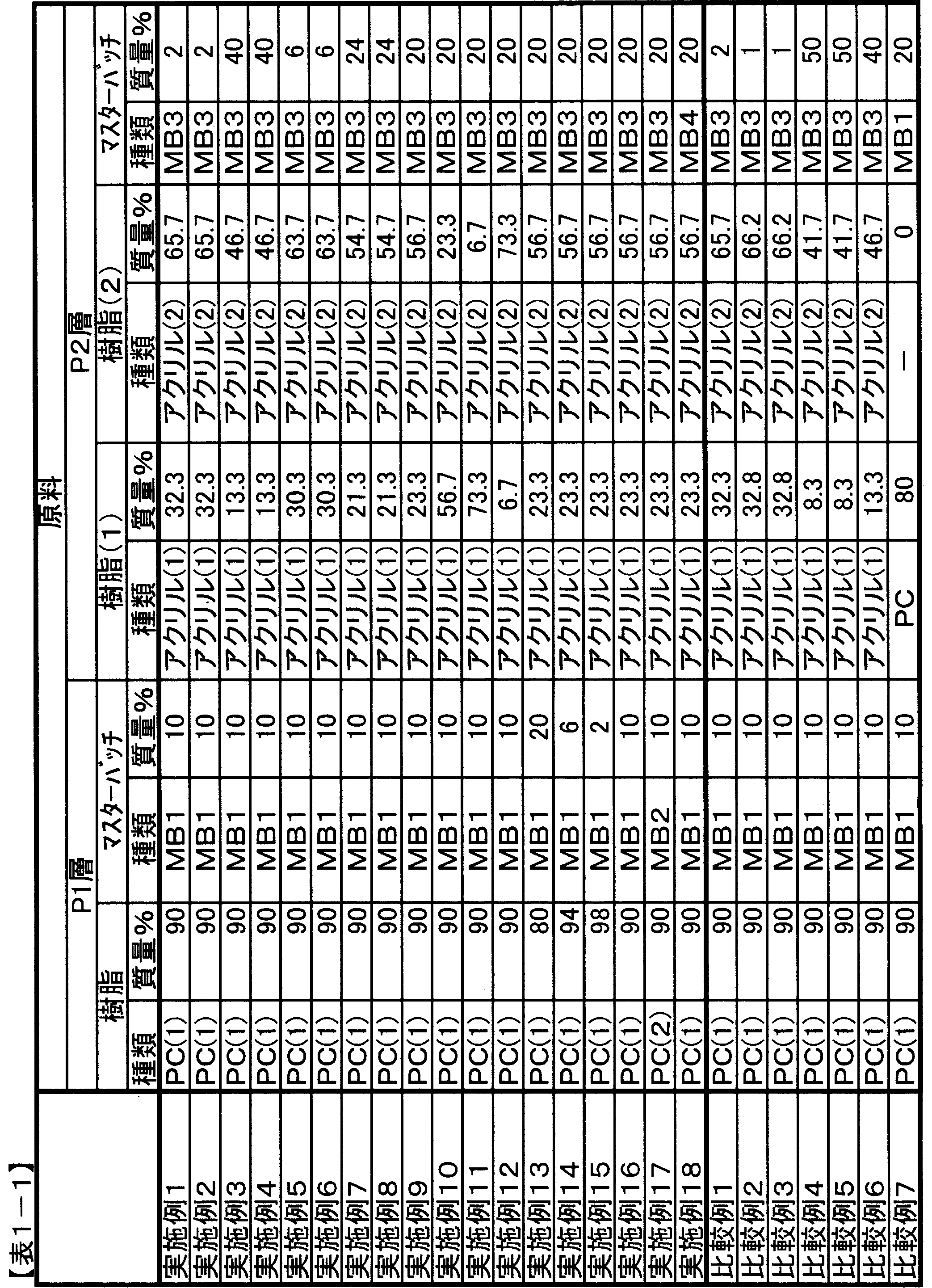
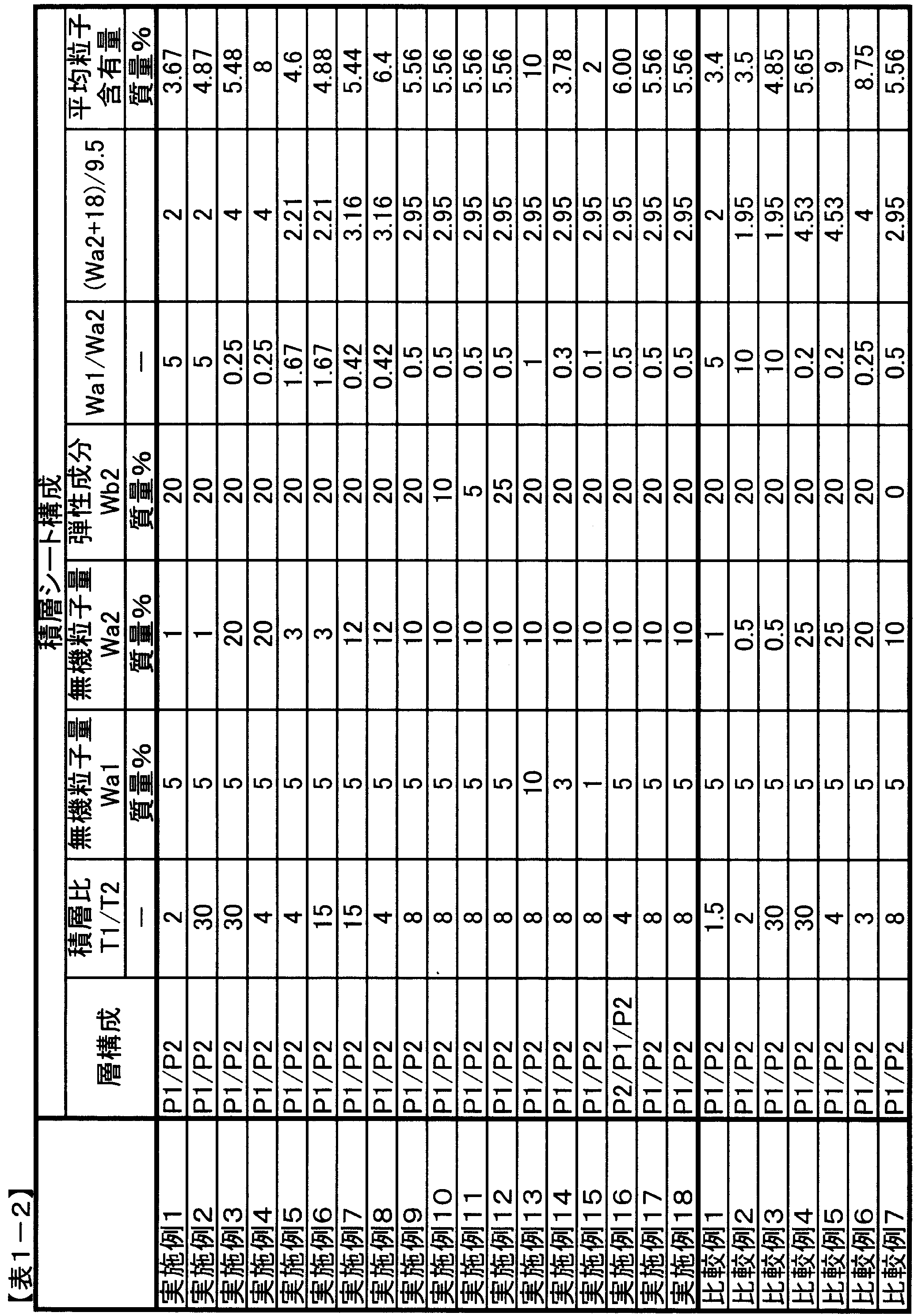

1:太陽電池用バックシート
2:封止剤層
3:発電素子
4:透明基板
5:太陽電池バックシートの封止剤層2側の面
6:太陽電池バックシートの封止剤層2と反対側の面
2:封止剤層
3:発電素子
4:透明基板
5:太陽電池バックシートの封止剤層2側の面
6:太陽電池バックシートの封止剤層2と反対側の面
Claims (7)
- ポリカーボネート系樹脂を主たる構成成分とする層(P1層)と、アクリル系樹脂を主たる構成成分とし、無機粒子含有率Wa2が1質量%以上20質量%以下である層(P2層)とを有する積層シートであって、P1層の層厚みT1とP2層の層厚みT2の比T1/T2が下記式(I)を満たすことを特徴とする積層シート。
(Wa2+18)/9.5≦T1/T2(I) - P1層に無機粒子を含有し、P1層の無機粒子含有率Wa1が0.1質量%以上15質量%以下である請求項1に記載の積層シート。
- P1層の無機粒子含有率Wa1とP2層の無機粒子含有率Wa2の比Wa1/Wa2が0.8以下である請求項1または2に記載の積層シート。
- 積層シートの一方の最外層がP1層であり、もう一方の最外層がP2層である請求項1~3のいずれかに記載の積層シート。
- 請求項1~4のいずれかに記載の積層シートを用いた太陽電池バックシート。
- 少なくとも一方の最外層がP2層である請求項5に記載の太陽電池バックシート。
- 請求項5または6に記載の太陽電池バックシートを用いた太陽電池。
Priority Applications (1)
| Application Number | Priority Date | Filing Date | Title |
|---|---|---|---|
| JP2013507584A JPWO2012133368A1 (ja) | 2011-03-30 | 2012-03-27 | 積層シートおよびそれを用いた太陽電池 |
Applications Claiming Priority (2)
| Application Number | Priority Date | Filing Date | Title |
|---|---|---|---|
| JP2011074637 | 2011-03-30 | ||
| JP2011-074637 | 2011-03-30 |
Publications (1)
| Publication Number | Publication Date |
|---|---|
| WO2012133368A1 true WO2012133368A1 (ja) | 2012-10-04 |
Family
ID=46931085
Family Applications (1)
| Application Number | Title | Priority Date | Filing Date |
|---|---|---|---|
| PCT/JP2012/057861 Ceased WO2012133368A1 (ja) | 2011-03-30 | 2012-03-27 | 積層シートおよびそれを用いた太陽電池 |
Country Status (3)
| Country | Link |
|---|---|
| JP (1) | JPWO2012133368A1 (ja) |
| TW (1) | TW201244940A (ja) |
| WO (1) | WO2012133368A1 (ja) |
Cited By (3)
| Publication number | Priority date | Publication date | Assignee | Title |
|---|---|---|---|---|
| JP2016193600A (ja) * | 2015-03-31 | 2016-11-17 | 三菱樹脂株式会社 | 積層体 |
| JPWO2015053328A1 (ja) * | 2013-10-11 | 2017-03-09 | 三菱瓦斯化学株式会社 | 耐擦傷性ポリカーボネート樹脂積層体 |
| KR102589053B1 (ko) * | 2022-12-27 | 2023-10-13 | (주)동신폴리켐 | 캐노피형 폴리카보네이트 태양광 모듈 |
Citations (8)
| Publication number | Priority date | Publication date | Assignee | Title |
|---|---|---|---|---|
| JPH05339400A (ja) * | 1992-06-15 | 1993-12-21 | Sekisui Chem Co Ltd | ポリカーボネート系成形体 |
| JPH06198823A (ja) * | 1992-12-28 | 1994-07-19 | Dainippon Plastics Co Ltd | 畜舎用波板 |
| JP2002067238A (ja) * | 2000-09-01 | 2002-03-05 | Nippon Kayaku Co Ltd | 放射線硬化型樹脂組成物の硬化皮膜を有するフィルム |
| JP2003211611A (ja) * | 2002-01-21 | 2003-07-29 | Harada Toso Kogyosho:Kk | ポリカーボネート樹脂積層体 |
| JP2003291277A (ja) * | 2002-03-29 | 2003-10-14 | Nissan Motor Co Ltd | 樹脂積層体 |
| JP2005037591A (ja) * | 2003-07-18 | 2005-02-10 | Idemitsu Petrochem Co Ltd | 光反射シート及びその成形品 |
| JP2006324556A (ja) * | 2005-05-20 | 2006-11-30 | Toppan Printing Co Ltd | 太陽電池用バックシートおよびそれを用いた太陽電池モジュール |
| JP2010215843A (ja) * | 2009-03-18 | 2010-09-30 | Mitsubishi Chemicals Corp | 活性エネルギー線硬化性組成物および積層体 |
-
2012
- 2012-03-27 WO PCT/JP2012/057861 patent/WO2012133368A1/ja not_active Ceased
- 2012-03-27 JP JP2013507584A patent/JPWO2012133368A1/ja active Pending
- 2012-03-29 TW TW101110959A patent/TW201244940A/zh unknown
Patent Citations (8)
| Publication number | Priority date | Publication date | Assignee | Title |
|---|---|---|---|---|
| JPH05339400A (ja) * | 1992-06-15 | 1993-12-21 | Sekisui Chem Co Ltd | ポリカーボネート系成形体 |
| JPH06198823A (ja) * | 1992-12-28 | 1994-07-19 | Dainippon Plastics Co Ltd | 畜舎用波板 |
| JP2002067238A (ja) * | 2000-09-01 | 2002-03-05 | Nippon Kayaku Co Ltd | 放射線硬化型樹脂組成物の硬化皮膜を有するフィルム |
| JP2003211611A (ja) * | 2002-01-21 | 2003-07-29 | Harada Toso Kogyosho:Kk | ポリカーボネート樹脂積層体 |
| JP2003291277A (ja) * | 2002-03-29 | 2003-10-14 | Nissan Motor Co Ltd | 樹脂積層体 |
| JP2005037591A (ja) * | 2003-07-18 | 2005-02-10 | Idemitsu Petrochem Co Ltd | 光反射シート及びその成形品 |
| JP2006324556A (ja) * | 2005-05-20 | 2006-11-30 | Toppan Printing Co Ltd | 太陽電池用バックシートおよびそれを用いた太陽電池モジュール |
| JP2010215843A (ja) * | 2009-03-18 | 2010-09-30 | Mitsubishi Chemicals Corp | 活性エネルギー線硬化性組成物および積層体 |
Cited By (3)
| Publication number | Priority date | Publication date | Assignee | Title |
|---|---|---|---|---|
| JPWO2015053328A1 (ja) * | 2013-10-11 | 2017-03-09 | 三菱瓦斯化学株式会社 | 耐擦傷性ポリカーボネート樹脂積層体 |
| JP2016193600A (ja) * | 2015-03-31 | 2016-11-17 | 三菱樹脂株式会社 | 積層体 |
| KR102589053B1 (ko) * | 2022-12-27 | 2023-10-13 | (주)동신폴리켐 | 캐노피형 폴리카보네이트 태양광 모듈 |
Also Published As
| Publication number | Publication date |
|---|---|
| JPWO2012133368A1 (ja) | 2014-07-28 |
| TW201244940A (en) | 2012-11-16 |
Similar Documents
| Publication | Publication Date | Title |
|---|---|---|
| EP1898470B1 (en) | Use of a back sheet for photovoltaic modules and resulting photovoltaic module | |
| CN102470653B (zh) | 聚酯膜及使用其的太阳能电池背板、太阳能电池 | |
| CN101823355B (zh) | 聚合物叠层膜和使用该叠层膜的太阳能电池板 | |
| JP5102392B2 (ja) | 太陽電池裏面保護膜用積層ポリエステルフィルム | |
| JP5304789B2 (ja) | ポリエステルフィルム、積層フィルムおよびそれを用いた太陽電池バックシート、太陽電池 | |
| EP2226350A1 (en) | Polyester film, method for production of the same, and area light source, solar battery back-sheet and solar battery each comprising the same | |
| CN103687907B (zh) | 偏氟乙烯系树脂组合物、树脂薄膜、太阳能电池用背板以及太阳能电池组件 | |
| CN103443932B (zh) | 太阳能电池用保护板,其制造方法,太阳能电池用背板部件,太阳能电池用背板和太阳能电池模块 | |
| JPWO2012133368A1 (ja) | 積層シートおよびそれを用いた太陽電池 | |
| WO2018034117A1 (ja) | 積層体、およびそれを用いた太陽電池裏面保護用シート、太陽電池モジュール | |
| JP5505018B2 (ja) | ポリエステルフィルム、それを用いた太陽電池バックシート、およびled光源用反射板。 | |
| JP5920338B2 (ja) | 積層シートおよびそれを用いた太陽電池 | |
| WO2016052133A1 (ja) | 積層体 | |
| WO2013015259A1 (ja) | 積層シートおよびその製造方法 | |
| JP5395597B2 (ja) | 太陽電池用表面保護シート | |
| CN101817245A (zh) | 太阳能电池组件 | |
| JP2013055270A (ja) | 積層シートおよびそれを用いた太陽電池 | |
| JP5807365B2 (ja) | ポリカーボネート系樹脂シートおよびそれを用いた太陽電池 | |
| JP2014004778A (ja) | 積層シートおよびその製造方法 | |
| JP2013052635A (ja) | 積層シートおよびそれを用いた太陽電池 | |
| JP5415247B2 (ja) | 太陽電池用表面保護シート | |
| CN106796967A (zh) | 太阳能电池模块用背面保护片、太阳能电池模块和太阳能电池模块用背面保护片的制造方法 | |
| JP2016096324A (ja) | 太陽電池裏面保護シートおよびそれを用いた太陽電池モジュール | |
| JP2016076537A (ja) | 太陽電池裏面保護用シートおよびその製造方法 | |
| JP2016213366A (ja) | 太陽電池裏面保護用シート |
Legal Events
| Date | Code | Title | Description |
|---|---|---|---|
| 121 | Ep: the epo has been informed by wipo that ep was designated in this application |
Ref document number: 12763093 Country of ref document: EP Kind code of ref document: A1 |
|
| ENP | Entry into the national phase |
Ref document number: 2013507584 Country of ref document: JP Kind code of ref document: A |
|
| NENP | Non-entry into the national phase |
Ref country code: DE |
|
| 122 | Ep: pct application non-entry in european phase |
Ref document number: 12763093 Country of ref document: EP Kind code of ref document: A1 |