WO2012133299A1 - 発電機モータ - Google Patents
発電機モータ Download PDFInfo
- Publication number
- WO2012133299A1 WO2012133299A1 PCT/JP2012/057741 JP2012057741W WO2012133299A1 WO 2012133299 A1 WO2012133299 A1 WO 2012133299A1 JP 2012057741 W JP2012057741 W JP 2012057741W WO 2012133299 A1 WO2012133299 A1 WO 2012133299A1
- Authority
- WO
- WIPO (PCT)
- Prior art keywords
- rotor
- generator motor
- side member
- flange
- locking
- Prior art date
- Legal status (The legal status is an assumption and is not a legal conclusion. Google has not performed a legal analysis and makes no representation as to the accuracy of the status listed.)
- Ceased
Links
Images





Classifications
-
- H—ELECTRICITY
- H02—GENERATION; CONVERSION OR DISTRIBUTION OF ELECTRIC POWER
- H02K—DYNAMO-ELECTRIC MACHINES
- H02K15/00—Processes or apparatus specially adapted for manufacturing, assembling, maintaining or repairing of dynamo-electric machines
- H02K15/14—Casings; Enclosures; Supports
-
- H—ELECTRICITY
- H02—GENERATION; CONVERSION OR DISTRIBUTION OF ELECTRIC POWER
- H02K—DYNAMO-ELECTRIC MACHINES
- H02K5/00—Casings; Enclosures; Supports
- H02K5/04—Casings or enclosures characterised by the shape, form or construction thereof
-
- H—ELECTRICITY
- H02—GENERATION; CONVERSION OR DISTRIBUTION OF ELECTRIC POWER
- H02K—DYNAMO-ELECTRIC MACHINES
- H02K15/00—Processes or apparatus specially adapted for manufacturing, assembling, maintaining or repairing of dynamo-electric machines
- H02K15/02—Processes or apparatus specially adapted for manufacturing, assembling, maintaining or repairing of dynamo-electric machines of stator or rotor bodies
-
- H—ELECTRICITY
- H02—GENERATION; CONVERSION OR DISTRIBUTION OF ELECTRIC POWER
- H02K—DYNAMO-ELECTRIC MACHINES
- H02K15/00—Processes or apparatus specially adapted for manufacturing, assembling, maintaining or repairing of dynamo-electric machines
- H02K15/50—Disassembling, repairing or modifying dynamo-electric machines
-
- H—ELECTRICITY
- H02—GENERATION; CONVERSION OR DISTRIBUTION OF ELECTRIC POWER
- H02K—DYNAMO-ELECTRIC MACHINES
- H02K5/00—Casings; Enclosures; Supports
-
- H—ELECTRICITY
- H02—GENERATION; CONVERSION OR DISTRIBUTION OF ELECTRIC POWER
- H02K—DYNAMO-ELECTRIC MACHINES
- H02K5/00—Casings; Enclosures; Supports
- H02K5/04—Casings or enclosures characterised by the shape, form or construction thereof
- H02K5/15—Mounting arrangements for bearing-shields or end plates
-
- H—ELECTRICITY
- H02—GENERATION; CONVERSION OR DISTRIBUTION OF ELECTRIC POWER
- H02K—DYNAMO-ELECTRIC MACHINES
- H02K7/00—Arrangements for handling mechanical energy structurally associated with dynamo-electric machines, e.g. structural association with mechanical driving motors or auxiliary dynamo-electric machines
- H02K7/14—Structural association with mechanical loads, e.g. with hand-held machine tools or fans
Definitions
- the present invention relates to a generator motor mounted on, for example, a hybrid hydraulic excavator.
- a so-called hybrid construction machine in which a generator motor is mounted between an engine and a hydraulic pump has been developed.
- the generator motor mounted on such a hybrid construction machine is connected to the output shaft of the engine and the input shaft of the hydraulic pump, and generates power by the driving force of the engine.
- the electric energy generated by the power generation by the generator motor is stored in a power storage device such as a capacitor.
- the generator motor is driven by the stored electric energy, and the engine To help output.
- Patent Document 1 discloses a generator motor (power unit) that supplies sufficient lubricating oil to spline coupling portions at both ends of a coupling shaft portion that spline-couples an output shaft of an engine and an input shaft of a hydraulic pump. ).
- the conventional generator motor has the following problems. That is, in the generator motor disclosed in the above publication, when it is necessary to disassemble the generator motor during maintenance or failure, it is usually necessary to remove components from the hydraulic pump side. For this reason, when disassembling the generator motor, after removing the hydraulic pump, first, the flange portion disposed on the hydraulic pump side is removed.
- the flange portion is lightly fitted to the rotor side member in the bearing portion, it is not fixed to the rotor side member, so that it can be detached independently by moving in the axial direction.
- the rotor-side member remaining on the fixed side (engine side) is restricted from moving outside in the axial direction by the flange portion.
- the rotor side member is housed in the housing of the generator motor so as to be rotatable with respect to the stator or the like which is the fixed side member, the rotor side member is moved in the axial direction between the stator side and the fixed side member. There is nothing to regulate.
- the rotor-side member moves together with the flange portion side depending on the magnitude relationship between the friction force at the flange bearing portion and the friction force at the engine-side spline engagement portion. It is decided whether to move or remain on the fixed side. For example, when the frictional force at the engine-side spline engaging portion is larger, the rotor-side member is left on the fixed side. On the other hand, when the frictional force at the bearing portion of the flange portion is larger, the rotor side member is removed together with the flange portion.
- the subject of this invention is providing the generator motor which can prevent that a rotor side member falls off from a fixed side, when disassembling a generator motor.
- the generator motor according to the first invention includes a flange portion, a fixed side member, a rotor side member, and a locking member.
- the flange portion is attached and detached on the first end side in the axial direction.
- the fixed side member is fixed to the second end side opposite to the first end in the axial direction.
- the rotor side member is movable to the first end side in the axial direction with respect to the fixed side member in a state where the flange portion is removed.
- the locking member restricts relative movement in the axial direction of the flange portion with respect to the rotor-side member.
- the flange side member is prevented from falling off from the fixed side member when the flange portion is removed.
- a locking member is provided for restricting movement of the portion relative to the rotor side member in the axial direction and moving the flange portion and the rotor side member integrally.
- the fixed side member and the rotor side member are in a relatively rotatable relationship with each other, they are not joined to each other, and are easily separated from each other unless pressed from the outside in the axial direction.
- the flange portion is a member that is first removed on the first end portion side that is a free end when the generator motor is disassembled, and holds the rotor side member of the generator motor in the housing. To act as a lid for. Therefore, in a state where the flange portion is removed, the rotor side member has nothing to be locked to the fixed side member, and if the flange portion is removed, the rotor side member may fall from the fixed side member. is there.
- a locking member is provided for restricting the relative movement in the axial direction of the flange portion with respect to the rotor-side member and moving both together.
- the said locking member may be provided in the flange part side, and may be provided in the rotor side member side.
- the generator motor according to the second invention is the generator motor according to the first invention, and the locking member is provided in the flange portion.
- a locking member for integrating the flange portion and the rotor side member in the axial direction is provided on the flange portion side.
- a generator motor according to a third invention is the generator motor according to the first or second invention, and the locking member is provided in the vicinity of the outer peripheral surface of the rotating shaft included in the rotor side member.
- a locking member that restricts the relative movement of the flange portion and the rotor side member in the axial direction is provided in the vicinity of the outer peripheral surface of the rotation shaft serving as the rotation center of the rotor side member.
- the flange portion can be easily moved relative to the rotor side member in the axial direction. Can be regulated.
- a generator motor according to a fourth invention is the generator motor according to any one of the first to third inventions, wherein the locking member is rotatable about a rotation axis, By the rotation of the locking member, a locking state in which the fixed side member and the rotor side member are integrated in the axial direction and a non-locking state in which the integration is released are switched.
- the locking member when releasing the integration of the flange portion and the rotor-side member, the locking member is rotated about the rotation shaft. Thereby, when disassembling the generator motor, the flange portion and the rotor side member removed from the fixed side member in a state of being integrated with each other can be easily separated simply by rotating the locking member. .
- a generator motor according to a fifth aspect of the present invention is the generator motor according to the fourth aspect of the present invention, further comprising a restriction groove that restricts the rotation range of the locking member.
- the rotation range of the rotatable locking member is regulated by the regulation groove.
- the said regulation groove part is provided in the surface at the side of the 1st end part of a flange part, for example.
- the rotor side member in a state where a part of the locking member is in contact with one end surface of the restriction groove portion, the rotor side member is brought into a first state where it is locked to the fixed side member, and the end surface on the opposite side of the restriction groove portion is formed.
- the rotor side member In the contacted state, the rotor side member can be in a second state opened to the fixed side member. Therefore, the first state and the second state can be easily switched by simply rotating the locking member within the range of the restriction groove.
- a generator motor according to a sixth invention is the generator motor according to any one of the first to fifth inventions, and the locking member is a substantially L-shaped member.
- a substantially L-shaped member is used as the locking member. Accordingly, the flange portion and the rotor side member can be easily integrated simply by hooking the end portion of the substantially L-shaped locking member on the step or groove formed on the rotor side member side.
- a generator motor according to a seventh aspect of the present invention is the generator motor according to any one of the first to sixth aspects of the invention, wherein the locking member has a predetermined gap between the rotating rotor side member. Have. Thereby, rotation of a rotor side member is not prevented by a locking member.
- a generator motor according to an eighth invention is the generator motor according to any one of the first to seventh inventions, wherein the fixed side member is a first housing fixed to the adjacent engine side, A second housing joined to the first housing; and a stator provided in a space in the first and second housings.
- the flange portion and the rotor-side member are removed, and then the first and second housings constituting the outer angle of the generator motor and the spaces in the first and second housings are provided.
- the fixed side member including the stator to be left is left.
- a generator motor according to a ninth aspect of the present invention is the generator motor according to any one of the first to eighth aspects of the present invention, wherein the rotor-side member includes a rotating shaft and a rotor that rotates around the rotating shaft. ,including.
- the rotor-side member that is removed in a state of being integrated with the flange portion includes the rotating shaft and the rotor. Therefore, only a rotating shaft, a rotor, etc. can be easily removed in the state which left the stator etc. in the stationary side member.
- a generator motor according to a tenth invention is a generator motor according to any one of the first to ninth inventions, and is disposed between an engine mounted on a construction machine and a hydraulic pump.
- the fixed side member is fixed to the engine.
- the fixed-side member left on the second end side when the generator motor is disassembled is Is fixed.
- the perspective view which shows the structure of the hybrid engine periphery in which the generator motor which concerns on one Embodiment of this invention is mounted.
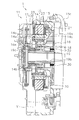
- Sectional drawing which shows the structure of the generator motor mounted in the hybrid type engine of FIG.
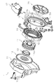
- the disassembled perspective view which shows the structure of the generator motor of FIG.
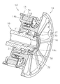
- the disassembled perspective view which shows the structure of the rotor side member removed in the state integrated with the flange when the generator motor of FIG. 2 is disassembled.
- the perspective view which shows the relationship between the rotor side member of FIG. 4, and a locking member.
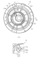
- the elements on larger scale of FIG. (A) is the perspective view which looked at the flange part from the engine side.
- (B) is a partially enlarged view thereof.
- Sectional drawing which shows the structure of the rotor side member contained in the generator motor which concerns on other embodiment of this invention.
- Sectional drawing which shows the structure of the rotor side member contained in the generator motor which concerns on further another embodiment of this invention.
- the axial direction, the radial direction, and the circumferential direction mean respective directions in a state where the generator motor 1 is incorporated.
- the axial direction means the axial direction of the rotating shaft 19 of the rotor 14 of the generator motor 1 (the left-right direction in FIG. 2).
- the radial direction means the radial direction of a circle around the rotation axis 19.
- the circumferential direction means the circumferential direction of a circle centered on the rotation shaft 19.
- the generator motor 1 As shown in FIG. 1, the generator motor 1 according to the present embodiment is mounted on a hybrid hydraulic excavator (construction machine) including an engine 2, a cooling fan 3, a hydraulic pump 4, a muffler 5, and the like. It is arranged between the engine 2 and the hydraulic pump 4.
- a hybrid hydraulic excavator includes a traveling body and a revolving body provided on the traveling body so as to be able to swivel.
- the swivel body includes a work machine, a cab, a counterweight, and an engine room.
- the swivel body is driven by a swivel electric motor that operates by electric energy from the generator motor 1 or the capacitor.
- the swing electric motor generates power by regeneration during deceleration of the swing body, and the electric energy obtained by the power generation is stored in the capacitor.
- the generator motor 1 has a rotary shaft 19 (see FIG. 2) connected directly or indirectly to the output shaft of the engine 2 and the input shaft of the hydraulic pump 4. Electricity is generated by the rotational driving force.
- the generator motor 1 is connected to a capacitor via an inverter. When the rotational speed of the engine 2 increases (the hydraulic excavator accelerates), the generator motor 1 is used as an electric motor by the electric energy stored in the capacitor as needed, and the rotation of the engine 2 Assist. When the engine 2 is in an idling state, the generator motor 1 receives the rotational driving force of the engine 2 to generate electric power, and electric energy generated by the electric power generation is stored in the capacitor.
- the generator motor 1 is a three-phase 12-pole SR (switched reluctance) motor, and as shown in FIGS. 2 and 3, a stator 10, a first housing 11, a flywheel 12, a coupling 13, The rotor 14, the second housing 15, the flange (flange portion) 16, and the rotating shaft 19 are provided.
- SR switched reluctance
- the stator 10 is provided in a space formed in the first and second housings 11 and 15 that constitute the outer shell of the generator motor 1. As shown in FIG. 2, the stator 10 includes an annular stator core 20, an insulator 21, a coil 23, and the like.
- the stator core 20 is configured by laminating a plurality of steel plates including an annular yoke portion and a portion of a stator tooth that is arranged along the circumferential direction and protrudes radially inward from the yoke portion. Yes.
- a stator core 20 including a total of 36 protrusions is used to form a three-phase 12-pole SR motor.
- the first housing 11 is a cast iron member, and as shown in FIG. 3, is joined to the second housing 15 to form a space in which the stator 10, the rotor 14 and the like are housed.
- an oil sump V is formed which promotes lubrication of the rotary shaft 19 and the bearing portion 18 and stores cooling oil for cooling the heat generating portion (the coil 23 and the like) of the stator 10. Yes.
- an oil inspection pipe (also used as an oil supply pipe) 11 a communicating with the oil sump V shown in FIG. 2 is connected to the lower end portion of the first housing 11.
- the cooling oil stored in the oil sump V in the first and second housings 11 and 15 is circulated by a circulation pump, and a cooling device (for example, a lower part of the second housing 15 is provided). After being cooled via the oil cooler 15d (see FIG. 3), it is returned to the space in the first and second housings 11 and 15 again.
- the flywheel 12 is provided on the output shaft side of the engine 2 in the first and second housings 11 and 15, is connected to the rotor 14 via the coupling 13, and is in the first and second housings 11 and 15. Rotate at.
- the coupling 13 is a substantially annular member and is bolted to the flywheel 12.
- a spline formed on the inner diameter side meshes with an external spline 19 a formed on the outer diameter side of the rotary shaft 19.
- the flywheel 12 and the coupling 13 rotate together with the rotor 14 around the rotation shaft 19.
- the rotary shaft 19 and the coupling 13 are splined in the rotational direction, they are not joined to each other in the axial direction and are restrained from the outside in the axial direction by the first and second housings 11 and 15. Without it, they are easily separated.
- the rotor 14 is a rotation-side member that rotates about the rotation shaft 19 and is inserted into a space on the inner peripheral side of the annular stator 10 in the storage space in the first and second housings 11 and 15.
- the rotor 14 has a holder 14b to which a rotor yoke 14a is attached on the outer peripheral surface.
- the rotor yoke 14a is a structure in which a plurality of steel plates (magnetic steel plates) are laminated, and is bolted to the outer peripheral surface side of the holder 14b as shown in FIG. 2, and on the outer peripheral surface side of the annular main body, A plurality of inductors (not shown) provided at equal angular intervals in the circumferential direction are provided.
- the rotor yoke 14a is held so as to be sandwiched between aluminum blades 14c and 14c provided on the engine 2 side and the hydraulic pump 4 side, respectively.
- Through-holes opened outward in the radial direction are formed on the outer peripheral surfaces of the blades 14c, 14c.
- cooling oil is injected from the through hole to the coil 23 disposed radially outward.
- the rotor yoke 14a can be hold
- the holder 14 b is bolted to the outer peripheral portion of the rotating shaft 19 with the rotating shaft 19 inserted in the center hole.
- the holder 14b is a steel member having a substantially cylindrical shape, and has a structure in which an inner cylindrical portion and an outer cylindrical portion are combined, and the outer peripheral surface of the inner cylindrical portion and the outer cylinder are combined.
- a bearing portion 18 is attached to the inner peripheral surface of the portion, and a rotor yoke 14a is attached to the outer peripheral surface of the outer cylindrical portion.
- the rotating shaft 19 is a cylindrical member that serves as the rotation center of the rotor 14 and has a through hole that penetrates from one end portion to the other end portion in the axial direction.
- An external spline 19a fitted to the internal teeth of the coupling 13 and an internal spline 19b fitted to the input shaft on the hydraulic pump 4 side are formed at the end on the hydraulic pump 4 side, respectively.
- the rotary shaft 19 is fixed in a state where a half on the hydraulic pump 4 side in the axial direction is inserted into the inner peripheral surface side of the cylindrical portion inside the flange 16.
- a locking groove 19c formed along the circumferential direction is formed on the outer peripheral surface of the rotary shaft 19 on the hydraulic pump 4 side. The locking member 30 inserted into the locking groove 19c will be described in detail later.
- the second housing 15 is a member made of cast iron, and is provided on the hydraulic pump 4 side in the generator motor 1, and together with the first housing 11, the flywheel 12, the coupling 13, A storage space for storing the rotor 14, the stator 10, and the rotating shaft 19 is formed.
- the second housing 15 has an oil cooler 15d for cooling the cooling oil.
- a cooling oil pipe 15a is connected to the outlet of the oil cooler 15d for sending the cooling oil to the upper part of the first and second housings 11 and 15.
- an electric box 17 to which the wiring of the coil 23 wound around the protrusion of the stator core 20 is connected via the insulator 21 is attached to the shoulder portion of the second housing 15.
- the cooling oil stored in the oil sump V is supplied to an inlet of an oil cooler 15d provided in the lower portion of the second housing 15 via a pipe (not shown) and a circulation pump via a pipe (not shown).
- the cooling oil pipe 15a connected to the outlet of the oil cooler 15d is used to supply the cooling oil sucked up from the oil sump V to the upper part of the space formed in the first and second housings 11 and 15. As shown in FIG. 2, the second housing 15 is connected to the upper connection portion.
- the flange 16 is a disk-shaped member arranged coaxially with the rotation shaft 19. Desired cooling oil is sent to the upper portion of the second housing 15 via the cooling oil pipe 15 a. A cooling oil passage 16a that leads to this portion is formed inside.
- the flange 16 is fixed to the hydraulic pump 4 side of the second housing 15 by a plurality of bolts.
- the flange 16 has a substantially cylindrical bearing support portion 16e that protrudes in the axial direction from a substantially disk-shaped surface.
- the bearing support portion 16e supports the bearing portion 18 on the substantially cylindrical outer peripheral surface side.
- the flange 16 has a regulation groove portion 16b into which a locking member 30 described later is inserted, a through hole 16c, and a central hole 16d (see FIG. 7A).
- a locking member 30 described later is inserted
- a through hole 16c a through hole 16c
- a central hole 16d a central hole 16d
- the cooling oil passage 16a allows the cooling oil flowing from the upper spaces in the first and second housings 11 and 15 to receive the bearing portion 18 and the spline (engagement) in which the rotor 14 and the rotary shaft 19 are in contact with the fixed member. Part)).
- a sufficient amount of lubricating oil is always supplied to the bearing portion 18 and the spline (engagement portion).
- the oil that moves through the cooling oil passage 16a in this way moves radially outward by the centrifugal force generated when the rotor side member 50 rotates, and is supplied to the coil 23 on the hydraulic pump 4 side to cool the coil 23. It also functions as a cooling oil.
- the oil lubricates and cools the spline portion on the engine 2 side through the through hole in the rotary shaft 19. Thereafter, this oil moves radially outward by the centrifugal force generated when the rotor-side member 50 rotates, and is used for cooling the coil 23 provided on the engine 2 side.
- the regulation groove 16b regulates the rotation range (rotation angle) of the locking portion 31 of the locking member 30 described later.
- a rotation shaft 32 of a locking member 30 to be described later is inserted into the through hole 16c and is fixed by a bolt and a nut (see FIG. 5).
- the center hole 16d is provided in the center of the disc-shaped flange 16, and the end of the rotary shaft 19 on the hydraulic pump 4 side is inserted in the state where the generator motor 1 is assembled.
- Locking member 30 In the generator motor 1 of this embodiment, as shown in FIG. 4, a locking member 30 is provided to restrict relative movement in the axial direction between the flange 16 and the rotor-side member 50.
- the locking member 30 is a member having a substantially L shape in a side sectional view, and includes a locking portion 31 and a rotation shaft 32.
- the locking portion 31 is a flat plate member that is inserted into the locking groove 19c of the rotating shaft 19, and as shown in FIG. 6, is rotated about a rotating shaft 32 (in FIG. 6). 2), switching between the locking state of the flange 16 with respect to the rotating shaft 19 (see the locking member 30 on the lower side in FIG. 6) and the locking state (see the locking member 30 on the upper side in FIG. 6). .
- the rotation shaft 32 is a columnar member serving as a rotation center of the locking member 30 and is inserted into a through hole 16c formed near the outer periphery of the center hole 16d of the flange 16 shown in FIG. In this state, the bolt 16 and the nut (see FIG. 6) are fixed to the flange 16 so as not to come out of the through hole 16c.
- the locking member 30 is inserted into the locking groove 19c of the rotating shaft 19, and the flange 16 and the rotating shaft 19 are integrated in the axial direction. It has become a state (locked state). At this time, the locking member 30 is inserted in a non-contact state with respect to the locking groove 19 c of the rotating shaft 19. For this reason, the provision of the locking member 30 does not adversely affect the rotation of the rotor-side member 50.
- the locking groove 19c preferably has such a width that a part of the locking member 30 does not contact even when the rotor-side member 50 moves in the axial direction due to the backlash of the rotary shaft 19.
- the generator motor 1 of the present embodiment has the above-described configuration, and a fixed-side member such as the first housing 11 is fixed to the engine 2 side (second end side) at the time of maintenance or failure. In this state, parts are removed from the hydraulic pump 4 side (first end side), which is the side close to the vehicle body opening, and disassembled.
- the rotor-side member 50 means a configuration excluding the flange 16 shown in FIG. 4, that is, a configuration including the rotor 14, the rotating shaft 19, and the like.
- the fixed-side member is a structure that is left on the engine 2 side after the rotor-side member 50 is removed from the generator motor 1, that is, the first and second housings 11 and 15, the stator 10, the flywheel 12, and the coupling. 13 is included.
- the flange 16 and the rotating shaft 19 are integrated in the axial direction by the locking member 30 described above. Thereby, when the flange 16 is removed, as shown in FIG. 4, the rotor side member 50 (the rotor 14, the bearing portion 18, and the rotating shaft 19) can be removed together with the flange 16.
- this is a locked state in which the locking portion 31 of the locking member 30 is inserted in the locking groove 19c formed on the outer peripheral surface of the rotating shaft 19 in a non-contact state.
- the rotating shaft 19 in the locked state and the member (the rotor 14 or the like) fixed to the rotating shaft 19 move in an integrated state. is there. That is, the locking part 31 is inserted in the locking groove 19c in a non-contact state in a direction perpendicular to the axial direction.
- the locking member 30 attached to the flange 16 also moves in the axial direction, and the tip of the locking portion 31 is on the hydraulic pump 4 side in the locking groove 19c. It abuts on the surface. For this reason, by moving the flange 16 in the axial direction, the rotating shaft 19 can be hooked in the portion of the locking groove 19c by the locking member 30 and can be moved integrally.
- the frictional force in the bearing portion 18 of the flange 16 and the engine 2 side is determined by the magnitude relationship with the frictional force at the spline engaging portion. For example, when the frictional force in the spline engaging portion on the engine 2 side is larger, the rotor side member 50 is left on the first housing 11 side. On the other hand, when the frictional force at the bearing portion 18 of the flange 16 is larger, the rotor side member 50 is removed together with the flange 16 and the rotary shaft 19.
- the locking member 30 is provided so that the rotor side member 50 can be integrated with the flange 16 side and reliably removed during disassembly work.
- the rotor 14 included in the rotor side member 50 is removed from the engine 2 side (fixed side) in a state where the flange 16 and the rotor side member 50 are integrated.
- an operation of separating the flange 16 and the rotor side member 50 is performed.
- the locking member 30 is attached to the flange 16 so as to be rotatable about the rotation shaft 32. For this reason, when releasing the locking state between the flange 16 and the rotor-side member 50, the locking member 30 is rotated about the rotation shaft 32.
- the locking portion 31 can be retracted from the locking groove 19c of the rotating shaft 19 like the locking member 30 arranged in the upper part of FIG. Accordingly, since the flange 16 is movable in the axial direction with respect to the rotating shaft 19, the locked state between the flange 16 and the rotor-side member 50 can be easily released.
- the locking portion 31 of the locking member 30 is rotated in the restriction groove portion 16b of the flange 16 shown in FIG. Switch between the stopped state.
- the state in which the side surface of the locking portion 31 of the locking member 30 is in contact with the first end surface 16ba of the V-shaped recess in the restriction groove portion 16b is the non-locking state, and the second end surface 16bb of the V-shaped recess.
- the regulation groove portion 16b is formed so that the state in contact with is in the locked state. Thereby, switching between the locked state and the non-locked state by the locking member 30 can be performed reliably and easily.
- a flange 16 that is attached and detached on the hydraulic pump 4 side in the axial direction, and a fixing that is fixed on the engine 2 side in the axial direction when the flange 16 is removed.
- Side members first and second housings 11 and 15, stator 10, etc.
- a rotor side member 50 that is movable toward the hydraulic pump 4 in the axial direction with respect to the fixed side member with the flange 16 removed
- a flange And 16 locking members 30 for restricting relative movement in the axial direction with respect to the rotor-side member 50.
- the rotor side member 50 can be removed in an integrated state. Therefore, the rotor side member 50 does not fall off from the fixed side after removing the flange 16 alone. As a result, it is possible to reliably prevent the rotor-side member 50 from falling off when the generator motor 1 is disassembled, and to prevent occurrence of breakage of components included in the rotor-side member 50.
- the locking member is inserted along the radial direction from the outer circumferential surface of the flange 116 in the radial direction, and reaches a locking groove 119 a formed on the outer circumferential surface of the rotating shaft 119. You may use the bolt member 130 which has these.
- the tip of the bolt member 130 is in a non-contact state in the locking groove 119a. For this reason, the relative movement in the axial direction of the rotating shaft 119 and the flange 116 can be restricted without affecting the rotation of the rotor-side member 150 in the assembled state of the generator motor. Therefore, when disassembling the generator motor, the flange 116 is removed in a state of being integrated with the rotor side member 150 including the rotating shaft 119 and the rotor 114, so that the rotor side member 150 is fixed after the flange 116 is removed. Falling off from the side can be prevented.
- the locking member is inserted along the axial direction from an opening formed on the surface of the flange 216 on the side of the hydraulic pump 4, and has a tip with respect to a blade 218 included in the rotor 214.
- a bolt member 230 to be screwed may be used.
- the bolt member 230 may be inserted from the surface of the flange 216 on the hydraulic pump side and fixed to the blade 218 when the generator motor is disassembled.
- the relative movement in the axial direction of the rotating shaft 219 and the flange 216 can be restricted and integrated. Accordingly, when disassembling the generator motor, the flange 216 is removed in a state of being integrated with the rotor side member 250 including the rotating shaft 219 and the rotor 214, thereby fixing the rotor side member 250 after the flange 216 is removed. Falling off from the side can be prevented.
- a rotating shaft included in the rotor side member or a locking member is provided on the rotor side, and the locking portion is hooked on a groove or a step of the flange to restrict relative movement in the axial direction. May be.
- the present invention can be applied to other construction machines such as hybrid type wheel loaders, bulldozers, dump trucks, and generator motors mounted on hybrid type automobiles.
- the engine 2 the generator motor 1, and the hydraulic pump 4 were given and demonstrated as the example arrange
- the present invention is not limited to this.
- a configuration in which a generator motor is directly connected to a PTO (power take-off) may be used.
- generator motor such as a PM (Permanent Magnet) motor may be used.
- the generator motor of the present invention has an effect of reliably preventing the rotor-side member from falling off from the stationary side when the generator motor is disassembled, and is thus mounted on various vehicles such as construction machines and passenger cars. It can be widely applied to generator motors.
Landscapes
- Engineering & Computer Science (AREA)
- Power Engineering (AREA)
- Manufacturing & Machinery (AREA)
- Connection Of Motors, Electrical Generators, Mechanical Devices, And The Like (AREA)
- Motor Or Generator Frames (AREA)
- Manufacture Of Motors, Generators (AREA)
Abstract
Description
このようなハイブリッド型の建設機械に搭載された発電機モータは、エンジンの出力軸と油圧ポンプの入力軸とに接続されており、エンジンの駆動力によって発電を行う。そして、発電機モータでの発電により生じた電気エネルギーはキャパシタなどの蓄電装置に蓄えられ、建設機械が大きなエンジン出力を要する場合等に、蓄えられた電気エネルギーによって発電機モータが駆動されて、エンジンの出力を補助する。
すなわち、上記公報に開示された発電機モータでは、メンテナンスや故障時等に発電機モータを分解する必要が生じた場合には、通常、油圧ポンプ側から部品を取り外していく必要がある。このため、発電機モータを分解する際には、油圧ポンプを取り外した後、まず、油圧ポンプ側に配置されたフランジ部を取り外すことになる。
本発明の課題は、発電機モータを分解する際に、固定側からロータ側部材が脱落してしまうことを防止することが可能な発電機モータを提供することにある。
これにより、自由端側となる第1端部側においてフランジ部を取り外した場合でも、ロータ側部材もフランジ部と一緒に取り外すことができる。よって、フランジ部だけが取り外されて、ロータ側部材が固定側部材に対して軸方向に自由に移動可能な状態になることを回避できる。この結果、発電機モータの分解時において、固定側からのロータ側部材の脱落を確実に防止することができる。
ここでは、フランジ部とロータ側部材とを軸方向において一体化する係止部材を、フランジ部側に設けている。
これにより、発電機モータを分解する際にフランジ部を取り外した場合でも、フランジ部に設けられた係止部材を、ロータ側部材の一部に引っ掛けることで、フランジ部とロータ側部材とを一体化した状態で、第1端部側において取り外すことができる。
ここでは、フランジ部とロータ側部材との軸方向における相対移動を規制する係止部材を、ロータ側部材の回転中心となる回転軸の外周面近傍に設けている。
これにより、発電機モータを分解する際に、互いに一体化した状態で固定側部材から取り外したフランジ部とロータ側部材とを、係止部材を回動させるだけで、容易に分離することができる。
ここでは、回動可能な係止部材の回動範囲を、規制溝部によって規制している。
これにより、係止部材の一部が規制溝部の一方の端面に当接した状態において、ロータ側部材が固定側部材に対して係止された第1状態とし、規制溝部の反対側の端面に当接した状態において、ロータ側部材が固定側部材に対して開放された第2状態とすることができる。よって、係止部材を規制溝部の範囲内において回動させるだけで、上記第1状態と第2状態とを容易に切り換えることができる。
ここでは、係止部材として、略L字型の部材を用いている。
これにより、略L字型の係止部材の端部をロータ側部材側に形成された段差や溝等に引っ掛けるだけで、フランジ部とロータ側部材とを容易に一体化させることができる。
これにより、係止部材によってロータ側部材の回転が妨げられることはない。
これにより、発電機モータの分解時においてフランジ部を取り外した際には、ロータ側部材だけをフランジ部と一体化して取り外すことができる。
これにより、固定側部材にステータ等を残した状態で、回転軸やロータ等だけを容易に取り外すことができる。
なお、以下の説明において、軸方向、径方向、周方向とは、発電機モータ1に組み込まれた状態でのそれぞれの方向を意味している。具体的には、軸方向とは、発電機モータ1のロータ14の回転軸19の軸方向(図2における左右方向)を意味している。径方向とは、回転軸19を中心とする円の半径方向を意味している。周方向とは、回転軸19を中心とする円の円周方向を意味している。
本実施形態に係る発電機モータ1は、図1に示すように、エンジン2、冷却ファン3、油圧ポンプ4およびマフラー5等を備えたハイブリッド型の油圧ショベル(建設機械)に搭載されており、エンジン2と、油圧ポンプ4との間に配置されている。ハイブリッド型の油圧ショベルは、走行体と、走行体に旋回可能に設けられた旋回体とを備えている。旋回体は、作業機、キャブ、カウンタウエイト、エンジンルームを備えている。旋回体は、発電機モータ1あるいはキャパシタからの電気エネルギーにより動作する旋回電動モータにて駆動される。旋回電動モータは、旋回体の減速時に回生により発電し、発電で得られた電気エネルギーは、キャパシタに蓄電される。
第1ハウジング11は、鋳鉄製の部材であって、図3に示すように、第2ハウジング15と接合されて、内部にステータ10やロータ14等を収納する空間を形成する。そして、この収納空間の下部には、回転軸19や軸受け部18の潤滑を促すとともに、ステータ10の発熱部(コイル23等)を冷却するための冷却油を貯留する油溜めVが形成されている。また、第1ハウジング11の下端部には、図3に示すように、図2に示す油溜めVに連通する検油管(給油管と兼用)11aが接続されている。
貫通孔16cには、後述する係止部材30の回動軸32が挿入されて、ボルトおよびナット(図5参照)によって固定される。
中央孔16dは、円盤状のフランジ16の中央に設けられており、発電機モータ1を組み立てた状態において、回転軸19の油圧ポンプ4側の端部が挿入される。
本実施形態の発電機モータ1では、図4に示すように、フランジ16とロータ側部材50との間における軸方向における相対移動を規制するために、係止部材30を設けている。
本実施形態の発電機モータ1は、上述した構成を備えており、メンテナンス時や故障等の際には、エンジン2側(第2端部側)に第1ハウジング11等の固定側部材が固定された状態で、車体開口部に近い側である油圧ポンプ4側(第1端部側)から部品を取り外して分解される。
これにより、発電機モータ1の分解工程において、フランジ16を取り外した際に、第1ハウジング11等の固定側部材に対してロータ側部材50が軸方向に移動可能な状態で残されることを回避することができる。この結果、フランジ16だけを取り外した後、固定側に残されたロータ側部材50が不意に脱落してしまうことを防止して、ロータ側部材50に含まれる各部品の破損等を防止することができる。
これにより、係止部材30による係止状態と非係止状態との切り換えを確実かつ容易に実施することができる。
本実施形態の発電機モータ1では、図4に示すように、軸方向における油圧ポンプ4側において着脱されるフランジ16と、フランジ16を取り外した際に軸方向におけるエンジン2側に固定された固定側部材(第1・第2ハウジング11,15、ステータ10等)と、フランジ16を取り外した状態において固定側部材に対して軸方向における油圧ポンプ4側に移動可能なロータ側部材50と、フランジ16のロータ側部材50に対する軸方向における相対移動を規制する係止部材30と、を備えている。
以上、本発明の一実施形態について説明したが、本発明は上記実施形態に限定されるものではなく、発明の要旨を逸脱しない範囲で種々の変更が可能である。
上記実施形態では、フランジ16を取り外した際にロータ側部材50と一体化させるための係止部材30として、回動軸32を中心として回動可能な略L字型の部材を用いた例を挙げて説明した。しかし、本発明はこれに限定されるものではない。
上記実施形態では、フランジ16を取り外した際にロータ側部材50と一体化させるための係止部材30として、回動軸32を中心として回動可能な略L字型の部材を用いた例を挙げて説明した。しかし、本発明はこれに限定されるものではない。
上記実施形態では、係止部材30がフランジ16側に設けられている例を挙げて説明した。しかし、本発明はこれに限定されるものではない。
上記実施形態では、係止部材30を2つ設けた例を挙げて説明した。しかし、本発明はこれに限定されるものではない。
例えば、フランジを取り外した際にロータ側部材と一体化させることができるものであれば、1つの係止部材を用いてもよいし、3つ以上の係止部材を用いてもよい。
上記実施形態では、本発明の発電機モータ1等を、ハイブリッド型の油圧ショベルに搭載した例を挙げて説明した。しかし、本発明はこれに限定されるものではない。
例えば、PTO(パワーテイクオフ)に対して、発電機モータが直接連結された構成であってもよい。
上記実施形態では、発電機モータ1として、SR(switched reluctance)モータを用いた例を挙げて説明した。しかし、本発明はこれに限定されるものではない。
2 エンジン
3 冷却ファン
4 油圧ポンプ
5 マフラー
10 ステータ(固定側部材)
11 第1ハウジング(固定側部材)
11a 検油管
12 フライホイール(固定側部材)
13 カップリング(固定側部材)
14 ロータ(ロータ側部材)
14a ロータヨーク
14b ホルダ
14c ブレード
15 第2ハウジング(固定側部材)
15a 冷却油配管
15d オイルクーラ
16 フランジ(フランジ部)
16a 冷却油通路
16b 規制溝部
16ba 第1端面
16bb 第2端面
16c 貫通孔
16d 中央孔
16e 軸受け支持部
17 電気ボックス
18 軸受け部
19 回転軸(ロータ側部材)
19a 外歯スプライン
19b 内歯スプライン
19c 係止溝
20 ステータコア
21 インシュレータ
23 コイル
30 係止部材
31 係止部
32 回動軸
50 ロータ側部材
114 ロータ
116 フランジ
119 回転軸
119a 係止溝
130 ボルト部材(係止部材)
150 ロータ側部材
214 ロータ
216 フランジ
218 ブレード
219 回転軸
230 ボルト部材(係止部材)
250 ロータ側部材
V 油溜め
Claims (10)
- 軸方向における第1端部側において着脱されるフランジ部と、
前記軸方向における前記第1端部とは反対側の第2端部側に固定された固定側部材と、
前記フランジ部を取り外した状態において、前記固定側部材に対して軸方向における前記第1端部側に移動可能なロータ側部材と、
前記フランジ部の前記ロータ側部材に対する軸方向における相対移動を規制する係止部材と、
を備えている発電機モータ。 - 前記係止部材は、前記フランジ部に設けられている、
請求項1に記載の発電機モータ。 - 前記係止部材は、前記ロータ側部材に含まれる回転軸の外周面の近傍に設けられている、
請求項1または2に記載の発電機モータ。 - 前記係止部材は、回動軸を中心に回動可能であって、
前記係止部材の回動により、前記固定側部材と前記ロータ側部材との軸方向において一体化する係止状態と、前記一体化を解除した非係止状態とが切り換えられる、
請求項1から3のいずれか1項に記載の発電機モータ。 - 前記係止部材の回動範囲を規制する規制溝部を、
さらに備えている、
請求項4に記載の発電機モータ。 - 前記係止部材は、略L字状の部材である、
請求項1から5のいずれか1項に記載の発電機モータ。 - 前記係止部材は、回転する前記ロータ側部材との間に所定の隙間を有している、
請求項1から6のいずれか1項に記載の発電機モータ。 - 前記固定側部材は、隣接するエンジン側に固定された第1ハウジングと、前記第1ハウジングに接合される第2ハウジングと、前記第1・第2ハウジング内の空間に設けられるステータと、を含む、
請求項1から7のいずれか1項に記載の発電機モータ。 - 前記ロータ側部材は、前記回転軸と、前記回転軸を中心に回転するロータと、を含む、
請求項1から8のいずれか1項に記載の発電機モータ。 - 建設機械に搭載されたエンジンと油圧ポンプとの間に配置されており、
前記固定側部材は、前記エンジンに対して固定されている、
請求項1から9のいずれか1項に記載の発電機モータ。
Priority Applications (4)
| Application Number | Priority Date | Filing Date | Title |
|---|---|---|---|
| US13/809,143 US8569919B2 (en) | 2011-03-31 | 2012-03-26 | Generator motor |
| DE112012000043T DE112012000043T5 (de) | 2011-03-31 | 2012-03-26 | Generatormotor |
| CN201280001949.2A CN102986122B (zh) | 2011-03-31 | 2012-03-26 | 发电电动机 |
| KR1020127033070A KR101313032B1 (ko) | 2011-03-31 | 2012-03-26 | 발전기 모터 |
Applications Claiming Priority (2)
| Application Number | Priority Date | Filing Date | Title |
|---|---|---|---|
| JP2011077240A JP5188591B2 (ja) | 2011-03-31 | 2011-03-31 | 発電機モータ |
| JP2011-077240 | 2011-03-31 |
Publications (1)
| Publication Number | Publication Date |
|---|---|
| WO2012133299A1 true WO2012133299A1 (ja) | 2012-10-04 |
Family
ID=46931017
Family Applications (1)
| Application Number | Title | Priority Date | Filing Date |
|---|---|---|---|
| PCT/JP2012/057741 Ceased WO2012133299A1 (ja) | 2011-03-31 | 2012-03-26 | 発電機モータ |
Country Status (6)
| Country | Link |
|---|---|
| US (1) | US8569919B2 (ja) |
| JP (1) | JP5188591B2 (ja) |
| KR (1) | KR101313032B1 (ja) |
| CN (1) | CN102986122B (ja) |
| DE (1) | DE112012000043T5 (ja) |
| WO (1) | WO2012133299A1 (ja) |
Families Citing this family (14)
| Publication number | Priority date | Publication date | Assignee | Title |
|---|---|---|---|---|
| JP5188591B2 (ja) * | 2011-03-31 | 2013-04-24 | 株式会社小松製作所 | 発電機モータ |
| JP5188593B2 (ja) * | 2011-03-31 | 2013-04-24 | 株式会社小松製作所 | 発電電動機の冷却構造及び発電電動機 |
| JP5779947B2 (ja) * | 2011-04-07 | 2015-09-16 | コベルコ建機株式会社 | ハイブリッド建設機械 |
| DE202013103023U1 (de) | 2012-07-14 | 2013-10-04 | Hitachi Koki Co., Ltd. | Elektrowerkzeug |
| DE112014004527A5 (de) * | 2013-10-01 | 2016-06-23 | Schaeffler Technologies AG & Co. KG | Aktor |
| DE102014204939B3 (de) * | 2014-03-17 | 2014-12-24 | Aptar Radolfzell Gmbh | Spender mit einer elektronische Betätigungserkennung |
| KR101697847B1 (ko) * | 2015-01-05 | 2017-01-18 | 한전케이피에스 주식회사 | 모터 커플링간 고정구조 |
| FR3049548B1 (fr) * | 2016-03-30 | 2019-06-14 | Alstom Transport Technologies | Moteur de vehicule ferroviaire et procede d'installation d'un moteur |
| CN106787436B (zh) * | 2017-01-13 | 2023-11-21 | 重庆星环航空科技有限公司 | 一种飞轮式发电机 |
| DE102018215462A1 (de) | 2018-09-12 | 2020-03-12 | Robert Bosch Gmbh | Rotor-Baugruppe für einen Elektromotor und Verfahren zum Einbau der Rotor-Baugruppe in ein Gehäuseteil des Elektromotors |
| CN115395708B (zh) * | 2021-05-25 | 2023-12-08 | 北京金风科创风电设备有限公司 | 发电装置及其维护方法和风力发电机组 |
| US12341402B2 (en) * | 2022-01-20 | 2025-06-24 | Schaeffler Technologies AG & Co. KG | Emotor rotor centering and shipping aid with annular disk and bolt holes |
| TWI840255B (zh) * | 2023-06-14 | 2024-04-21 | 陳宜豊 | 電磁鐵應用發電裝置 |
| EP4725734A1 (en) * | 2024-10-08 | 2026-04-15 | FPT Industrial S.p.A. | Hybridization assembly for an endothermic engine and endothermic engine including the assembly |
Citations (4)
| Publication number | Priority date | Publication date | Assignee | Title |
|---|---|---|---|---|
| JPH01149009U (ja) * | 1988-04-06 | 1989-10-16 | ||
| JP2007174752A (ja) * | 2005-12-20 | 2007-07-05 | Hino Motors Ltd | 電動発電機およびその組立て方法 |
| JP2010154593A (ja) * | 2008-12-24 | 2010-07-08 | Nissan Motor Co Ltd | 車両用モーター取付け方法 |
| JP2010272254A (ja) * | 2009-05-19 | 2010-12-02 | Komatsu Ltd | コネクタおよび建設機械 |
Family Cites Families (8)
| Publication number | Priority date | Publication date | Assignee | Title |
|---|---|---|---|---|
| JPH01149009A (ja) * | 1987-12-07 | 1989-06-12 | Sumitomo Electric Ind Ltd | 光ケーブル用スペーサおよびその製造方法 |
| WO2006121045A1 (ja) * | 2005-05-10 | 2006-11-16 | Komatsu Ltd. | エンジンに搭載されるジェネレータ/モータ |
| CA2616066A1 (en) * | 2005-08-10 | 2007-02-15 | Tm4 Inc. | Electric machine provided with an internal stator |
| US8207643B2 (en) * | 2008-07-16 | 2012-06-26 | Sununwealth Electric Machine Industry Co., Ltd. | Motor including a stator bobbin having a bearing abutting member |
| CN100373066C (zh) * | 2006-04-27 | 2008-03-05 | 孙宜培 | 管状电机离合器开关 |
| JP5064945B2 (ja) | 2007-09-10 | 2012-10-31 | 株式会社小松製作所 | パワーユニット |
| WO2011101911A1 (ja) * | 2010-02-19 | 2011-08-25 | トヨタ自動車株式会社 | 動力伝達装置の潤滑構造 |
| JP5188591B2 (ja) * | 2011-03-31 | 2013-04-24 | 株式会社小松製作所 | 発電機モータ |
-
2011
- 2011-03-31 JP JP2011077240A patent/JP5188591B2/ja active Active
-
2012
- 2012-03-26 DE DE112012000043T patent/DE112012000043T5/de not_active Withdrawn
- 2012-03-26 WO PCT/JP2012/057741 patent/WO2012133299A1/ja not_active Ceased
- 2012-03-26 US US13/809,143 patent/US8569919B2/en not_active Expired - Fee Related
- 2012-03-26 CN CN201280001949.2A patent/CN102986122B/zh not_active Expired - Fee Related
- 2012-03-26 KR KR1020127033070A patent/KR101313032B1/ko not_active Expired - Fee Related
Patent Citations (4)
| Publication number | Priority date | Publication date | Assignee | Title |
|---|---|---|---|---|
| JPH01149009U (ja) * | 1988-04-06 | 1989-10-16 | ||
| JP2007174752A (ja) * | 2005-12-20 | 2007-07-05 | Hino Motors Ltd | 電動発電機およびその組立て方法 |
| JP2010154593A (ja) * | 2008-12-24 | 2010-07-08 | Nissan Motor Co Ltd | 車両用モーター取付け方法 |
| JP2010272254A (ja) * | 2009-05-19 | 2010-12-02 | Komatsu Ltd | コネクタおよび建設機械 |
Also Published As
| Publication number | Publication date |
|---|---|
| KR101313032B1 (ko) | 2013-10-01 |
| CN102986122A (zh) | 2013-03-20 |
| JP5188591B2 (ja) | 2013-04-24 |
| US8569919B2 (en) | 2013-10-29 |
| CN102986122B (zh) | 2014-08-20 |
| JP2012213267A (ja) | 2012-11-01 |
| US20130119803A1 (en) | 2013-05-16 |
| DE112012000043T5 (de) | 2013-05-16 |
| KR20130024927A (ko) | 2013-03-08 |
Similar Documents
| Publication | Publication Date | Title |
|---|---|---|
| JP5188591B2 (ja) | 発電機モータ | |
| US8836180B2 (en) | Generator motor cooling structure and generator motor | |
| KR101617251B1 (ko) | 건설 기계 | |
| JP5956203B2 (ja) | 電動機 | |
| JP5060630B1 (ja) | 発電電動機の冷却構造及び発電電動機 | |
| KR101441995B1 (ko) | 인슐레이터 및 이를 구비한 스테이터, 모터 | |
| US8907534B2 (en) | Generator motor cooling structure and generator motor | |
| EP3323192B1 (en) | Adaptor for generator | |
| JP2022118472A (ja) | 電動車両 | |
| KR101290840B1 (ko) | 발전 전동기의 윤활 구조 및 발전 전동기 | |
| WO2019150672A1 (ja) | 電動機、回転駆動システム及び油圧ショベル | |
| JP5129870B2 (ja) | 発電電動機の冷却構造及び発電電動機 | |
| JP2015216819A (ja) | モータ構造体 | |
| JP2021151126A (ja) | モータ及び作業機械 | |
| JP2013176247A (ja) | 回転電機の潤滑装置 | |
| JP2007126065A (ja) | ハイブリッド原動機におけるモータ回転軸の軸受け装置 | |
| JP5079750B2 (ja) | 建設機械 | |
| JP2025073159A (ja) | 電動モータ及び作業機械 |
Legal Events
| Date | Code | Title | Description |
|---|---|---|---|
| WWE | Wipo information: entry into national phase |
Ref document number: 201280001949.2 Country of ref document: CN |
|
| 121 | Ep: the epo has been informed by wipo that ep was designated in this application |
Ref document number: 12764544 Country of ref document: EP Kind code of ref document: A1 |
|
| ENP | Entry into the national phase |
Ref document number: 20127033070 Country of ref document: KR Kind code of ref document: A |
|
| WWE | Wipo information: entry into national phase |
Ref document number: 13809143 Country of ref document: US |
|
| WWE | Wipo information: entry into national phase |
Ref document number: 112012000043 Country of ref document: DE Ref document number: 1120120000439 Country of ref document: DE |
|
| 122 | Ep: pct application non-entry in european phase |
Ref document number: 12764544 Country of ref document: EP Kind code of ref document: A1 |