WO2012133123A1 - タービン排気構造及びガスタービン - Google Patents
タービン排気構造及びガスタービン Download PDFInfo
- Publication number
- WO2012133123A1 WO2012133123A1 PCT/JP2012/057388 JP2012057388W WO2012133123A1 WO 2012133123 A1 WO2012133123 A1 WO 2012133123A1 JP 2012057388 W JP2012057388 W JP 2012057388W WO 2012133123 A1 WO2012133123 A1 WO 2012133123A1
- Authority
- WO
- WIPO (PCT)
- Prior art keywords
- exhaust
- turbine
- diffuser
- pressure loss
- gas
- Prior art date
Links
Images


Classifications
-
- F—MECHANICAL ENGINEERING; LIGHTING; HEATING; WEAPONS; BLASTING
- F01—MACHINES OR ENGINES IN GENERAL; ENGINE PLANTS IN GENERAL; STEAM ENGINES
- F01D—NON-POSITIVE DISPLACEMENT MACHINES OR ENGINES, e.g. STEAM TURBINES
- F01D9/00—Stators
- F01D9/02—Nozzles; Nozzle boxes; Stator blades; Guide conduits, e.g. individual nozzles
-
- F—MECHANICAL ENGINEERING; LIGHTING; HEATING; WEAPONS; BLASTING
- F02—COMBUSTION ENGINES; HOT-GAS OR COMBUSTION-PRODUCT ENGINE PLANTS
- F02C—GAS-TURBINE PLANTS; AIR INTAKES FOR JET-PROPULSION PLANTS; CONTROLLING FUEL SUPPLY IN AIR-BREATHING JET-PROPULSION PLANTS
- F02C7/00—Features, components parts, details or accessories, not provided for in, or of interest apart form groups F02C1/00 - F02C6/00; Air intakes for jet-propulsion plants
-
- F—MECHANICAL ENGINEERING; LIGHTING; HEATING; WEAPONS; BLASTING
- F01—MACHINES OR ENGINES IN GENERAL; ENGINE PLANTS IN GENERAL; STEAM ENGINES
- F01D—NON-POSITIVE DISPLACEMENT MACHINES OR ENGINES, e.g. STEAM TURBINES
- F01D25/00—Component parts, details, or accessories, not provided for in, or of interest apart from, other groups
- F01D25/30—Exhaust heads, chambers, or the like
-
- F—MECHANICAL ENGINEERING; LIGHTING; HEATING; WEAPONS; BLASTING
- F05—INDEXING SCHEMES RELATING TO ENGINES OR PUMPS IN VARIOUS SUBCLASSES OF CLASSES F01-F04
- F05D—INDEXING SCHEME FOR ASPECTS RELATING TO NON-POSITIVE-DISPLACEMENT MACHINES OR ENGINES, GAS-TURBINES OR JET-PROPULSION PLANTS
- F05D2250/00—Geometry
- F05D2250/50—Inlet or outlet
- F05D2250/52—Outlet
-
- F—MECHANICAL ENGINEERING; LIGHTING; HEATING; WEAPONS; BLASTING
- F05—INDEXING SCHEMES RELATING TO ENGINES OR PUMPS IN VARIOUS SUBCLASSES OF CLASSES F01-F04
- F05D—INDEXING SCHEME FOR ASPECTS RELATING TO NON-POSITIVE-DISPLACEMENT MACHINES OR ENGINES, GAS-TURBINES OR JET-PROPULSION PLANTS
- F05D2260/00—Function
- F05D2260/20—Heat transfer, e.g. cooling
- F05D2260/213—Heat transfer, e.g. cooling by the provision of a heat exchanger within the cooling circuit
Definitions
- the present invention is, for example, disposed in a rear part of a turbine in a gas turbine that supplies fuel to compressed high-temperature and high-pressure air to burn and supplies the generated combustion gas to the turbine to obtain rotational power.
- the present invention relates to a turbine exhaust structure and a gas turbine to which the turbine exhaust structure is applied.
- the gas turbine is composed of a compressor, a combustor, and a turbine, and the air taken in from the air intake port is compressed by the compressor to become high-temperature / high-pressure compressed air.
- the fuel is supplied and burned, and the high-temperature and high-pressure combustion gas drives the turbine, and the generator connected to the turbine is driven.
- the turbine is configured by alternately arranging a plurality of stationary blades and moving blades in the vehicle interior, and rotationally drives an output shaft connected to the generator by driving the moving blades with combustion gas. ing.
- the energy of the combustion gas (exhaust gas) that has driven the turbine is gradually converted to a pressure and released to the atmosphere so that no loss occurs by the exhaust diffuser.
- the exhaust diffuser is configured so that its flow passage area increases from the turbine outlet, that is, from the diffuser inlet toward the flow direction of the exhaust gas.
- the exhaust gas after being recovered can be decelerated to restore the pressure.
- Patent Document 1 As a gas turbine having such an exhaust diffuser, for example, there is one described in Patent Document 1 below.
- the turbine efficiency is improved and the performance of the gas turbine is improved.
- it is effective to increase the outlet channel area compared to the inlet channel area.
- the exhaust diffuser if the outlet flow passage area is suddenly increased compared to the inlet flow passage area, the exhaust gas flow is separated near the outer peripheral wall surface and the central wall surface of the exhaust diffuser, and the pressure is increased. The amount of recovery will be small.
- the exhaust diffuser if the outlet flow passage area is not abruptly increased compared to the inlet flow passage area, the length of the exhaust diffuser in the longitudinal direction (exhaust gas flow direction) becomes large, and the exhaust diffuser It will increase the size.
- An object of the present invention is to solve the above-described problems and to provide a turbine exhaust structure and a gas turbine capable of improving turbine efficiency by improving pressure efficiency of exhaust gas and improving performance. To do.
- a turbine exhaust structure of the present invention is provided with a casing having a cylindrical shape and constituting a combustion gas passage, and an exhaust diffuser having a cylindrical shape and constituting an exhaust gas passage is connected to the casing.
- a pressure loss body is provided in the exhaust diffuser.
- the exhaust gas that has recovered power from the combustion gas and flows to the exhaust diffuser is rectified and uniformed by the pressure loss body, near the wall of the exhaust diffuser. Since the exhaust gas is less likely to be peeled off, the pressure recovery amount here is increased, and efficient exhaust gas pressure recovery can improve the turbine efficiency and improve the performance. .
- the pressure loss body has a porous member disposed in an exhaust gas passage in the exhaust diffuser.
- the pressure loss body with a porous member arranged in the exhaust gas passage, not only can the exhaust gas pressure be recovered efficiently, but also the rigidity of the exhaust diffuser can be simplified while the structure can be simplified. Can be raised.
- the turbine exhaust structure of the present invention is characterized in that the pressure loss body has a heat transfer tube for exchanging heat between the exhaust gas and a heat exchange medium flowing inside.
- the pressure loss body with a heat transfer tube, it is possible to efficiently recover the pressure of the exhaust gas and to effectively recover the thermal energy of the exhaust gas.
- the pressure loss body is set such that the pressure loss of at least one of the radially outer side and the inner side of the exhaust diffuser is smaller than the pressure loss on the intermediate side in the radial direction. It is characterized by that.
- the exhaust gas flowing through the exhaust diffuser flows from the radially intermediate side where the pressure loss is large to the outside and inside of the radial direction where the pressure loss is small, thereby suppressing separation of the exhaust gas near the wall surface of the exhaust diffuser.
- the pressure recovery amount can be increased.
- a support structure that penetrates the exhaust diffuser in the radial direction is provided, and the pressure loss body is disposed downstream of the support structure in the flow direction of the exhaust gas. It is said.
- the pressure loss body on the downstream side of the strut where the exhaust gas is easily separated from the vicinity of the wall surface, the separation of the exhaust gas from the vicinity of the wall surface of the exhaust diffuser can be effectively suppressed.
- the gas turbine of the present invention is a gas turbine that obtains rotational power by supplying fuel to compressed air compressed by a compressor and burning it with a combustor and supplying the generated combustion gas to the turbine.
- the stationary blade body and the moving blade body are alternately arranged along the flow direction of the combustion gas in a cylindrical casing, and a cylindrical exhaust diffuser is connected to the casing, and pressure is applied to the exhaust diffuser.
- a lossy body is provided.
- the exhaust gas that has recovered power from the combustion gas and flows to the exhaust diffuser is rectified and uniformed by the pressure loss body, near the wall of the exhaust diffuser. Since the exfoliation of the exhaust gas is less likely to occur, the amount of pressure recovery here will increase, and by efficiently recovering the pressure of the exhaust gas, the turbine efficiency will be improved and the performance of the gas turbine will be improved. Can do.
- the pressure loss body is provided in the exhaust diffuser, the flow of the exhaust gas flowing in the exhaust diffuser is rectified and uniformed by the pressure loss body, and the wall surface of the exhaust diffuser Since exhaust gas separation in the vicinity is less likely to occur, the amount of pressure recovery here will increase, and efficient exhaust gas pressure recovery will improve turbine efficiency and improve performance Can do.
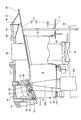
- FIG. 1 is a schematic diagram illustrating a turbine exhaust structure in a gas turbine according to a first embodiment of the present invention.
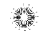
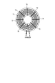
- FIG. 2 is a front view illustrating a pressure loss body in the turbine exhaust structure of the first embodiment.
- FIG. 3 is a front view illustrating another pressure loss body in the turbine exhaust structure of the first embodiment.
- FIG. 4 is a side view showing another pressure loss body in the turbine exhaust structure of the first embodiment.
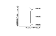
- FIG. 5 is a graph showing the pressure at the radial height of the exhaust diffuser.
- FIG. 6 is a schematic diagram illustrating a gas turbine according to the first embodiment.
- FIG. 7 is a schematic diagram illustrating a turbine exhaust structure in the gas turbine according to the second embodiment of the present invention.
- FIG. 8 is a front view illustrating a pressure loss body in the turbine exhaust structure of the second embodiment.
- FIG. 1 is a schematic view showing a turbine exhaust structure in a gas turbine according to Embodiment 1 of the present invention
- FIG. 2 is a front view showing a pressure loss body in the turbine exhaust structure of Embodiment 1
- FIG. 4 is a side view showing another pressure loss body in the turbine exhaust structure of the first embodiment
- FIG. 5 is a diagram showing the height in the radial direction of the exhaust diffuser.
- FIG. 6 is a schematic diagram illustrating the gas turbine according to the first embodiment.
- the gas turbine of Example 1 is composed of a compressor 11, a combustor 12, and a turbine 13 as shown in FIG.
- a generator (not shown) is connected to the gas turbine and can generate power.
- the compressor 11 has an air intake 21 for taking in air, and a plurality of stationary blade bodies 23 and moving blade bodies 24 are alternately arranged in the compressor casing 22 in the front-rear direction (the axial direction of the rotor 32 described later).
- the bleed chamber 25 is provided on the outside thereof.
- the combustor 12 is combustible by supplying fuel to the compressed air compressed by the compressor 11 and igniting it.
- a plurality of stationary blade bodies 27 and moving blade bodies 28 are alternately arranged in a turbine casing (casing) 26 in the front-rear direction (the axial direction of a rotor 32 described later).
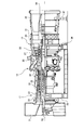
- An exhaust chamber 30 is disposed downstream of the turbine casing 26 via an exhaust casing 29, and the exhaust chamber 30 has an exhaust diffuser 31 that is continuous with the turbine 13.
- a rotor (turbine shaft) 32 is positioned so as to penetrate through the center of the compressor 11, the combustor 12, the turbine 13, and the exhaust chamber 30.
- the end of the rotor 32 on the compressor 11 side is rotatably supported by the bearing portion 33, while the end of the exhaust chamber 30 side is rotatably supported by the bearing portion 34.
- the rotor 32 is fixed by stacking a plurality of disks on which the rotor blade bodies 24 are mounted in the compressor 11, and a plurality of disks on which the rotor blade bodies 28 are mounted in the turbine 13.
- a generator drive shaft (not shown) is connected to the end on the compressor 11 side.
- the compressor casing 22 of the compressor 11 is supported by the legs 35
- the turbine casing 26 of the turbine 13 is supported by the legs 36
- the exhaust chamber 30 is supported by the legs 37.
- the air taken in from the air intake 21 of the compressor 11 passes through the plurality of stationary blade bodies 23 and the moving blade bodies 24 and is compressed to become high-temperature and high-pressure compressed air.
- a predetermined fuel is supplied to the compressed air in the combustor 12 and burned.
- the high-temperature and high-pressure combustion gas that is the working fluid generated in the combustor 12 passes through the plurality of stationary blade bodies 27 and the moving blade bodies 28 that constitute the turbine 13 to drive and rotate the rotor 32.
- a generator connected to the rotor 32 is driven.
- the energy of the exhaust gas (combustion gas) is converted into pressure by the exhaust diffuser 31 in the exhaust chamber 30 and decelerated before being released to the atmosphere.
- a turbine casing 26 having a cylindrical shape has a plurality of stationary blade bodies 27 and moving blade bodies 28 alternately arranged along the flow direction of the combustion gas. It is arranged.
- the turbine casing 26 is provided with a cylindrical exhaust casing 29 on the downstream side in the flow direction of the exhaust gas.
- the exhaust casing 29 is provided with a cylindrical exhaust chamber 30 on the downstream side in the exhaust gas flow direction.
- the exhaust chamber 30 is provided with an exhaust duct (not shown) on the downstream side in the flow direction of the exhaust gas.
- the turbine casing 26, the exhaust casing 29, the exhaust chamber 30, and the exhaust duct are each formed in two upper and lower parts, and both are integrally connected.
- the turbine casing 26 and the exhaust casing 29 are connected by a plurality of connecting bolts 41, and the exhaust casing 29 and the exhaust chamber 30 are connected by a plurality of exhaust chamber supports 42 and 43 capable of absorbing thermal expansion.
- the exhaust chamber supports 42 and 43 have a strip shape, are extended along the axial direction of the turbine 13, and are arranged in parallel at a predetermined interval in the circumferential direction.
- the exhaust chamber supports 42 and 43 are capable of absorbing the thermal expansion by deforming when thermal expansion occurs due to a temperature difference between the exhaust casing 29 and the exhaust chamber 30. This thermal elongation is likely to occur during a transition period such as when the turbine 13 is started or during a high load.
- a gas seal 44 is provided between the exhaust chamber 29 and the exhaust chamber 30 so as to be positioned between the exhaust chamber supports 42 and 43.
- the exhaust casing 29 is provided with an exhaust diffuser 31 having a cylindrical shape that constitutes the exhaust chamber 30 inside.
- the exhaust diffuser 31 includes a cylindrical outer diffuser 45 and an inner diffuser 46 connected by a plurality of strut shields 47.
- the strut shield 47 has a hollow structure such as a cylindrical shape or an elliptical cylinder shape, and a plurality of strut shields 47 are provided at equal intervals in the circumferential direction of the exhaust diffuser 31.
- the exhaust chamber supports 42 and 43 and the gas seal 44 described above are connected to the outer diffuser 45 in the exhaust diffuser 31 constituting the exhaust chamber 30 at the ends.
- a strut (support structure) 48 is disposed in the strut shield 47.
- One end of the strut 48 is connected to a bearing box 49 that passes through the inner diffuser 46 and accommodates the bearing portion 34, and the rotor 32 is rotatably supported by the bearing 34.
- the other end side of the strut 48 passes through the outer diffuser 45 and is fixed to the exhaust casing 29.
- the space inside the strut shield 47 communicates with the space inside the exhaust diffuser 31 (inner diffuser 46) and the space between the exhaust casing 29 and the exhaust diffuser 31 (outer diffuser 45). Cooling air can be supplied to the space.
- the turbine casing 26 has a plurality of stationary blade bodies 27 and moving blade bodies 28 arranged alternately inside thereof, and the blade ring structure of each stage has a substantially similar configuration.
- the stationary blade body 27 includes a plurality of stationary blades 27a arranged at equal intervals in the circumferential direction, an inner shroud 27b fixed to the proximal end portion on the rotor 32 side, and an outer shroud on the distal end portion on the turbine casing 26 side. 27c is fixed and configured.
- the rotor blade body 28 has the rotor blades 28a arranged at equal intervals in the circumferential direction, the base end portion fixed to the rotor disk 28b fixed to the rotor 32, and the tip end portion facing the turbine casing 26 side. It is configured to be extended.
- the final stage moving blade 28a is disposed downstream of the final stage stationary blade 27a.
- the final stage blade ring structure in the turbine casing 26 includes a cylindrical turbine casing main body 51, a cylindrical blade ring 52 provided inside the turbine casing main body 51, and a final stage moving blade.
- a split ring 53 that is arranged outside of 28a and has a cylindrical shape, and heat shield rings 54, 55, and 56 that connect the split ring 53 and the blade ring 52 to the outer shroud 27c of the final stage stationary blade 27a. .
- the combustion gas passage A is configured by the inner shroud 27b, the split ring 53, and the like that configure the turbine casing 26, and the turbine casing 26 and the exhaust gas are exhausted.
- An exhaust gas passage B constituted by the exhaust diffuser 31 is configured by the front part of the exhaust diffuser 31 entering the inside of the rear part of the passenger compartment 29 with a predetermined gap in the radial direction and connected by a sealing device 57.
- the combustion gas passage A and the exhaust gas passage B are continuous.
- a pressure loss body 61 is provided in the exhaust diffuser 31.
- the pressure loss body 61 is disposed downstream of the strut 48 in the exhaust gas flow direction.
- the pressure loss body 61 is provided as a porous member disposed in the exhaust gas passage B of the exhaust diffuser 31, and the radially outer side (outer diffuser 45) and inner side (external diffuser 45) of the exhaust gas passage B of the exhaust diffuser 31.
- the pressure loss of the inner diffuser 46) is set smaller than the pressure loss on the intermediate side in the radial direction.
- the pressure loss body 61 has a ring shape and is arranged on the downstream side of the strut 48, the inner periphery is fixed to the inner diffuser 46, and the outer periphery is The outer diffuser 45 is fixed.
- the pressure loss body 61 includes a plurality of rings 62 having different diameters along the circumferential direction of the exhaust diffuser 31 and a plurality of spokes 63 along the radial direction of the exhaust diffuser 31, and the plurality of rings 62 includes a plurality of spokes. 63 is supported by the inner diffuser 46 and the outer diffuser 45.
- the plurality of rings 62 are configured such that the distance between the radially outer peripheral portion and the inner peripheral portion in the exhaust diffuser 31 is set larger than the spacing between the radial intermediate portions.
- the pressure loss at the outer peripheral portion and the inner peripheral portion is set smaller than the pressure loss at the intermediate portion.
- the plurality of spokes 63 are arranged at equal intervals in the circumferential direction.
- the pressure loss body 61 was comprised from the some ring 62 and the some spoke 63, it is not limited to this structure.
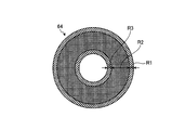
- the pressure loss body 64 is formed as a mesh made of a wire mesh, and the opening ratio of the region R1 on the outer peripheral portion side and the region R3 on the inner peripheral portion side is larger than that of the region R2 on the intermediate portion side. Since the rate is set to be large, the pressure loss body 64 is set such that the pressure loss at the outer peripheral portion and the inner peripheral portion is set smaller than the pressure loss at the intermediate portion in the exhaust gas passage B in the exhaust diffuser 31. It becomes. Further, as shown in FIG.
- the pressure loss body 65 is formed as a porous body (porous member) having a predetermined thickness, and the thickness T1 on the outer peripheral portion side and the thickness T3 on the inner peripheral portion side are the intermediate portion side.
- This pressure loss body 65 is set so that the pressure loss at the outer peripheral portion and the inner peripheral portion is smaller than the pressure loss at the intermediate portion in the exhaust gas passage B in the exhaust diffuser 31. Will be.
- the pressure loss body 61 since the pressure loss body 61 has a high pressure loss in the radial intermediate portion, the exhaust gas flowing in this region flows to the outer peripheral side in the radial direction or the inner peripheral side in the radial direction, and the outer diffuser Exfoliation of the exhaust gas from the inner wall 45 and the outer wall of the inner diffuser 46 is suppressed.
- the total exhaust gas pressure from the radially outer peripheral side to the inner peripheral side in the exhaust diffuser is substantially constant, and the outer diffuser or inner Exfoliation of the exhaust gas tends to occur near the wall of the diffuser, and the pressure recovery amount in the exhaust diffuser becomes small.
- the pressure diffuser 61 is provided in the exhaust diffuser 31, and the pressure loss in the intermediate portion in the radial direction is large. The total pressure of the exhaust gas on the side and the inner peripheral side becomes high, the exhaust gas is less likely to be peeled near the wall surfaces of the outer diffuser 45 and the inner diffuser 46, and the pressure recovery amount in the exhaust diffuser 31 is increased.
- the turbine casing 26 is provided which forms the combustion gas passage A in a cylindrical shape, and the exhaust gas passage B has a cylindrical shape in the turbine casing 26.
- the exhaust gas passage B has a cylindrical shape in the turbine casing 26.
- a pressure loss body 61 is provided in the exhaust diffuser 31.
- the exhaust gas that has recovered power from the combustion gas in the combustion gas passage A and flows into the exhaust gas passage B of the exhaust diffuser 31 is caused by the pressure loss body 61.
- the flow is rectified and uniformed, and the separation of the exhaust gas flow in the vicinity of the wall surface of the exhaust diffuser 31 is less likely to occur. Therefore, the pressure recovery amount here increases, and the exhaust gas pressure is efficiently recovered.
- the turbine efficiency can be improved and the performance can be improved.
- the length of the exhaust diffuser 31 can be shortened.
- the pressure loss body 61 is a porous member composed of a large number of rings 62 and a large number of spokes 63. Therefore, by configuring the pressure loss body 61 with the porous member disposed in the exhaust gas passage B, the exhaust diffuser 31 can not only efficiently recover the pressure of the exhaust gas but also simplify the structure. The rigidity of can be increased.
- the pressure loss body 61 sets the pressure loss at the outer peripheral portion and the inner peripheral portion in the radial direction of the exhaust diffuser 31 to be smaller than the pressure loss at the intermediate portion in the radial direction. . Therefore, the exhaust gas flowing through the exhaust diffuser 31 flows from the intermediate portion where the pressure loss is large to the outer peripheral portion and the inner peripheral portion where the pressure loss is small, and the separation of the exhaust gas in the vicinity of the wall surface of the exhaust diffuser 31 is suppressed. , The amount of pressure recovery can be increased.
- a strut 48 that penetrates the exhaust diffuser 31 in the radial direction and connects and supports the bearing box 49 and the exhaust casing 29 is provided, and the pressure loss body 61 is provided by the strut 48. It arrange
- the gas turbine of the present invention is configured so that the compressed air compressed by the compressor 11 is supplied with fuel by the combustor 12 and burned, and the generated combustion gas is supplied to the turbine 13 to obtain rotational power.
- the stationary blade bodies 27 and the rotor blade bodies 28 are alternately arranged along the flow direction of the combustion gas inside the cylindrical turbine casing 26, and the cylindrical exhaust diffuser 31 is formed at the rear of the turbine casing 26.
- the turbine 13 is connected to each other, and a pressure loss body 61 is provided in the exhaust diffuser 31.
- the pressure loss body 61 in the exhaust diffuser 31 the flow of exhaust gas flowing into the exhaust diffuser 31 is rectified and uniformed by the pressure loss body 61, and the exhaust diffuser 31 has a radial intermediate portion.
- the total pressure of the exhaust gas at the outer peripheral portion and the inner peripheral portion is increased, and the exhaust gas is less likely to be peeled off in the vicinity of the wall surface of the exhaust diffuser 31, so that the amount of pressure recovery is increased and efficient.
- FIG. 7 is a schematic view showing a turbine exhaust structure in a gas turbine according to a second embodiment of the present invention
- FIG. 8 is a front view showing a pressure loss body in the turbine exhaust structure of the second embodiment.
- symbol is attached
- the exhaust diffuser 31 is provided with a heat transfer tube 71 as a pressure loss body.
- the heat transfer tube 71 is disposed downstream of the strut 48 in the exhaust gas flow direction.
- the pressure loss on the radially outer side and the inner side in the exhaust diffuser 31 is set to be smaller than the pressure loss on the intermediate side in the radial direction.
- the heat transfer tube 71 exchanges heat between the exhaust gas flowing through the exhaust diffuser 31 and the cooling medium (heat exchange medium) flowing inside.
- a heat transfer tube of a waste heat recovery boiler (not shown) is applied.
- the heat transfer tube 71 is disposed so as to reciprocate in the circumferential direction in the exhaust gas passage B of the exhaust diffuser 31, and is supported by the inner diffuser 46 and the outer diffuser 45 by a plurality of spokes 72.
- the heat transfer tube 71 has an exhaust gas passage B in the exhaust diffuser 31 that is set such that the distance between the outer peripheral portion and the inner peripheral portion in the radial direction in the exhaust diffuser 31 is larger than the interval between the intermediate portions in the radial direction.
- the pressure loss at the outer peripheral portion and the inner peripheral portion is set to be smaller than the pressure loss at the intermediate portion.
- the power is recovered by the rotor blade body 28 and then flows into the exhaust gas passage B of the exhaust diffuser 31 as exhaust gas.
- the energy of the exhaust gas gradually increases. It is converted into pressure and released into the atmosphere.
- the exhaust diffuser 31 when the exhaust gas passes through the heat transfer pipe 71, the exhaust gas is rectified and uniformed to ensure a high pressure recovery amount. That is, since the heat transfer tube 71 has a high pressure loss in the radial intermediate portion, the exhaust gas flowing in this region flows to the outer peripheral side in the radial direction or the inner peripheral side in the radial direction. Exfoliation of the exhaust gas from the inner wall and the outer wall of the inner diffuser 46 is suppressed, and the pressure recovery amount in the exhaust diffuser 31 is increased.
- the turbine casing 26 that forms the combustion gas passage A in a cylindrical shape is provided, and the exhaust gas passage B has a cylindrical shape in the turbine casing 26.
- the exhaust diffuser 31 is provided with a heat transfer tube 71 as a pressure loss body.
- the heat transfer tube 71 in the exhaust diffuser 31 can exchange heat between the exhaust gas flowing through the exhaust diffuser 31 and the cooling medium flowing inside, so that the heat of the exhaust gas can be recovered and effectively used. it can.
- the pressure diffuser 61, 64, 65, 71 is provided in the exhaust diffuser 31, and the radially outer and inner pressure losses in the exhaust diffuser 31 are set to be smaller than the intermediate pressure loss.
- the pressure loss bodies 61, 64, 65, 71 are disposed downstream of the strut 48 in the flow direction of the exhaust gas, it is desirable to provide the exhaust gas in the region where the exhaust gas flowing through the exhaust diffuser 31 is separated from the wall surface. Depending on the shape of 31, it may be arranged near the strut 48 or upstream of the strut 48.
Landscapes
- Engineering & Computer Science (AREA)
- Mechanical Engineering (AREA)
- General Engineering & Computer Science (AREA)
- Chemical & Material Sciences (AREA)
- Combustion & Propulsion (AREA)
- Supercharger (AREA)
- Turbine Rotor Nozzle Sealing (AREA)
- Structures Of Non-Positive Displacement Pumps (AREA)
Abstract
Description
12 燃焼器
13 タービン
26 タービン車室(ケーシング)
27 静翼体
28 動翼体
29 排気車室
30 排気室
31 排気ディフューザ
32 ロータ
45 外側ディフューザ
46 内側ディフューザ
48 ストラット(支持構造体)
61,64,65 圧力損失体
62 リング
63 スポーク
71 伝熱管(圧力損失体)
A 燃焼ガス通路
B 排気ガス通路
Claims (6)
- 円筒形状をなして燃焼ガス通路を構成するケーシングが設けられ、前記ケーシングに円筒形状をなして排気ガス通路を構成する排気ディフューザが連結されるタービン排気構造において、
前記排気ディフューザに圧力損失体が設けられる、
ことを特徴とするタービン排気構造。 - 前記圧力損失体は、前記排気ディフューザにおける排気ガス通路に配置される多孔部材を有することを特徴とする請求項1に記載のタービン排気構造。
- 前記圧力損失体は、排気ガスと内部を流動する熱交換媒体との間で熱交換を行う伝熱管を有することを特徴とする請求項1に記載のタービン排気構造。
- 前記圧力損失体は、前記排気ディフューザにおける径方向の外側及び内側のうちの少なくともいずれか一方の圧力損失が、径方向の中間側の圧力損失よりも小さく設定されることを特徴とする請求項1から3のいずれか一つに記載のタービン排気構造。
- 前記排気ディフューザを径方向に貫通する支持構造体が設けられ、前記圧力損失体は、前記支持構造体より排気ガスの流動方向の下流側に配置されることを特徴とする請求項1から4のいずれか一つに記載のタービン排気構造。
- 圧縮機で圧縮した圧縮空気に燃焼器で燃料を供給して燃焼し、発生した燃焼ガスをタービンに供給することで回転動力を得るガスタービンにおいて、
前記タービンは、円筒形状をなすケーシング内に静翼体と動翼体が燃焼ガスの流動方向に沿って交互に配置され、前記ケーシングに円筒形状をなす排気ディフューザが連結されて構成され、
前記排気ディフューザに圧力損失体が設けられる、
ことを特徴とするガスタービン。
Priority Applications (4)
| Application Number | Priority Date | Filing Date | Title |
|---|---|---|---|
| CN201280015503.5A CN103459781B (zh) | 2011-03-29 | 2012-03-22 | 涡轮排气结构及燃气轮机 |
| US14/008,434 US9845689B2 (en) | 2011-03-29 | 2012-03-22 | Turbine exhaust structure and gas turbine |
| KR1020137025437A KR101522484B1 (ko) | 2011-03-29 | 2012-03-22 | 터빈 배기 구조 및 가스 터빈 |
| EP12763837.7A EP2692998B1 (en) | 2011-03-29 | 2012-03-22 | Turbine exhaust structure and gas turbine |
Applications Claiming Priority (2)
| Application Number | Priority Date | Filing Date | Title |
|---|---|---|---|
| JP2011073027A JP5951187B2 (ja) | 2011-03-29 | 2011-03-29 | タービン排気構造及びガスタービン |
| JP2011-073027 | 2011-03-29 |
Publications (1)
| Publication Number | Publication Date |
|---|---|
| WO2012133123A1 true WO2012133123A1 (ja) | 2012-10-04 |
Family
ID=46930850
Family Applications (1)
| Application Number | Title | Priority Date | Filing Date |
|---|---|---|---|
| PCT/JP2012/057388 WO2012133123A1 (ja) | 2011-03-29 | 2012-03-22 | タービン排気構造及びガスタービン |
Country Status (6)
| Country | Link |
|---|---|
| US (1) | US9845689B2 (ja) |
| EP (1) | EP2692998B1 (ja) |
| JP (1) | JP5951187B2 (ja) |
| KR (1) | KR101522484B1 (ja) |
| CN (1) | CN103459781B (ja) |
| WO (1) | WO2012133123A1 (ja) |
Cited By (1)
| Publication number | Priority date | Publication date | Assignee | Title |
|---|---|---|---|---|
| CN103790656A (zh) * | 2012-10-29 | 2014-05-14 | 通用电气公司 | 涡轮机排气罩和相关安装方法 |
Families Citing this family (13)
| Publication number | Priority date | Publication date | Assignee | Title |
|---|---|---|---|---|
| US20150059312A1 (en) * | 2013-08-29 | 2015-03-05 | General Electric Company | Exhaust stack having a co-axial silencer |
| JP6203090B2 (ja) | 2014-03-14 | 2017-09-27 | 三菱日立パワーシステムズ株式会社 | 排気室入口側部材、排気室、ガスタービンおよび最終段タービン動翼取出方法 |
| CN108291452B (zh) * | 2015-11-26 | 2020-10-30 | 三菱日立电力系统株式会社 | 燃气轮机及燃气轮机的部件温度调节方法 |
| US10982544B2 (en) | 2016-12-26 | 2021-04-20 | Mitsubishi Heavy Industries, Ltd. | Turbine and gas turbine |
| JP6731359B2 (ja) * | 2017-02-14 | 2020-07-29 | 三菱日立パワーシステムズ株式会社 | 排気ケーシング、及びこれを備える蒸気タービン |
| KR101902240B1 (ko) * | 2017-04-18 | 2018-09-28 | 두산중공업 주식회사 | 가변형 가이드 베인을 포함하는 배기 디퓨저 및 이를 포함하는 가스터빈 |
| KR102080566B1 (ko) * | 2018-01-03 | 2020-02-24 | 두산중공업 주식회사 | 연소기의 냉각구조와 이를 포함하는 연소기 및 가스터빈 |
| KR102080567B1 (ko) * | 2018-01-03 | 2020-02-24 | 두산중공업 주식회사 | 연소기의 냉각구조와 이를 포함하는 연소기 및 가스터빈 |
| KR102095035B1 (ko) * | 2018-02-09 | 2020-03-30 | 두산중공업 주식회사 | 연소기 및 이를 포함하는 가스터빈 |
| KR102095034B1 (ko) | 2018-02-09 | 2020-03-30 | 두산중공업 주식회사 | 연소기 및 이를 포함하는 가스터빈 |
| CN109404053A (zh) * | 2018-11-27 | 2019-03-01 | 德阳九鼎电气有限公司 | 一种用于汽轮机的导流隔板 |
| CN109372637B (zh) * | 2018-12-16 | 2021-04-16 | 中国航发沈阳发动机研究所 | 一种燃气轮机排气装置流路设计方法 |
| KR102217633B1 (ko) * | 2019-03-26 | 2021-02-22 | 두산중공업 주식회사 | 가스터빈의 스트럿 구조체, 이를 포함하는 배기 디퓨저 및 가스터빈 |
Citations (4)
| Publication number | Priority date | Publication date | Assignee | Title |
|---|---|---|---|---|
| JPH0861087A (ja) * | 1994-08-23 | 1996-03-05 | Hitachi Ltd | ガスタービン排気構造 |
| JP2002364310A (ja) * | 2001-06-06 | 2002-12-18 | Mitsubishi Heavy Ind Ltd | 排気ディフューザ |
| JP2009203871A (ja) | 2008-02-27 | 2009-09-10 | Mitsubishi Heavy Ind Ltd | 排気室の連結構造及びガスタービン |
| JP2011032900A (ja) * | 2009-07-30 | 2011-02-17 | Mitsubishi Heavy Ind Ltd | 流路構造及びガスタービン排気ディフューザ |
Family Cites Families (17)
| Publication number | Priority date | Publication date | Assignee | Title |
|---|---|---|---|---|
| US2674845A (en) * | 1951-05-02 | 1954-04-13 | Walter D Pouchot | Diffuser apparatus with boundary layer control |
| FR2612250B1 (fr) * | 1986-12-18 | 1991-04-05 | Vibrachoc Sa | Dispositif d'echappement d'une turbine a gaz, comportant un diffuseur de jets |
| US5020318A (en) * | 1987-11-05 | 1991-06-04 | General Electric Company | Aircraft engine frame construction |
| JP3513170B2 (ja) | 1993-02-26 | 2004-03-31 | 三菱重工業株式会社 | 排気ディフューザー |
| DE4422700A1 (de) | 1994-06-29 | 1996-01-04 | Abb Management Ag | Diffusor für Turbomaschine |
| JPH08260905A (ja) * | 1995-03-28 | 1996-10-08 | Mitsubishi Heavy Ind Ltd | 軸流タービン用排気ディフューザ |
| US5813828A (en) * | 1997-03-18 | 1998-09-29 | Norris; Thomas R. | Method and apparatus for enhancing gas turbo machinery flow |
| DE19737507A1 (de) * | 1997-08-28 | 1999-03-11 | Dampers Engineering Gmbh | Anordnung zur Beeinflussung des Dralls eines Abgasstroms |
| JP2006183665A (ja) | 2004-12-03 | 2006-07-13 | Doshisha | 流送通路断面積増加装置 |
| EP1921278A1 (en) * | 2006-11-13 | 2008-05-14 | ALSTOM Technology Ltd | Diffuser and exhaust system for turbine |
| EP1970539A1 (de) * | 2007-03-13 | 2008-09-17 | Siemens Aktiengesellschaft | Diffusoranordnung |
| WO2008143556A1 (en) * | 2007-05-22 | 2008-11-27 | Volvo Aero Corporation | A masking arrangement for a gas turbine engine |
| JP2009030512A (ja) | 2007-07-26 | 2009-02-12 | Doshisha | 流送通路断面積増加装置に付設されるコア部材及びコア部材を備えた流送通路断面積増加装置 |
| US7578369B2 (en) * | 2007-09-25 | 2009-08-25 | Hamilton Sundstrand Corporation | Mixed-flow exhaust silencer assembly |
| US8313286B2 (en) * | 2008-07-28 | 2012-11-20 | Siemens Energy, Inc. | Diffuser apparatus in a turbomachine |
| US8146341B2 (en) * | 2008-09-22 | 2012-04-03 | General Electric Company | Integrated gas turbine exhaust diffuser and heat recovery steam generation system |
| US8109720B2 (en) * | 2009-03-31 | 2012-02-07 | General Electric Company | Exhaust plenum for a turbine engine |
-
2011
- 2011-03-29 JP JP2011073027A patent/JP5951187B2/ja active Active
-
2012
- 2012-03-22 CN CN201280015503.5A patent/CN103459781B/zh not_active Expired - Fee Related
- 2012-03-22 EP EP12763837.7A patent/EP2692998B1/en not_active Not-in-force
- 2012-03-22 WO PCT/JP2012/057388 patent/WO2012133123A1/ja active Application Filing
- 2012-03-22 KR KR1020137025437A patent/KR101522484B1/ko active IP Right Grant
- 2012-03-22 US US14/008,434 patent/US9845689B2/en active Active
Patent Citations (4)
| Publication number | Priority date | Publication date | Assignee | Title |
|---|---|---|---|---|
| JPH0861087A (ja) * | 1994-08-23 | 1996-03-05 | Hitachi Ltd | ガスタービン排気構造 |
| JP2002364310A (ja) * | 2001-06-06 | 2002-12-18 | Mitsubishi Heavy Ind Ltd | 排気ディフューザ |
| JP2009203871A (ja) | 2008-02-27 | 2009-09-10 | Mitsubishi Heavy Ind Ltd | 排気室の連結構造及びガスタービン |
| JP2011032900A (ja) * | 2009-07-30 | 2011-02-17 | Mitsubishi Heavy Ind Ltd | 流路構造及びガスタービン排気ディフューザ |
Non-Patent Citations (1)
| Title |
|---|
| See also references of EP2692998A4 * |
Cited By (1)
| Publication number | Priority date | Publication date | Assignee | Title |
|---|---|---|---|---|
| CN103790656A (zh) * | 2012-10-29 | 2014-05-14 | 通用电气公司 | 涡轮机排气罩和相关安装方法 |
Also Published As
| Publication number | Publication date |
|---|---|
| KR101522484B1 (ko) | 2015-05-21 |
| US20140023493A1 (en) | 2014-01-23 |
| JP5951187B2 (ja) | 2016-07-13 |
| EP2692998B1 (en) | 2017-05-10 |
| EP2692998A4 (en) | 2014-10-08 |
| CN103459781B (zh) | 2015-04-15 |
| EP2692998A1 (en) | 2014-02-05 |
| KR20130135928A (ko) | 2013-12-11 |
| CN103459781A (zh) | 2013-12-18 |
| US9845689B2 (en) | 2017-12-19 |
| JP2012207565A (ja) | 2012-10-25 |
Similar Documents
| Publication | Publication Date | Title |
|---|---|---|
| JP5951187B2 (ja) | タービン排気構造及びガスタービン | |
| JP5991865B2 (ja) | ガスタービンエンジンおよびガスタービンエンジン用の一体型ケース/ステータセグメント | |
| JP5181114B2 (ja) | 高圧力比後方ファン組立体及びガスタービンエンジン | |
| KR101720476B1 (ko) | 가스 터빈 | |
| JP2008082323A (ja) | 二軸ガスタービン | |
| JP5600234B2 (ja) | ガスタービンエンジン組立体 | |
| JP2017040262A (ja) | ガスタービンエンジン用のスプリット端壁を有するcmcノズル | |
| JP2017133503A (ja) | 高opr(t3)エンジン用圧縮機後方ロータリムの冷却 | |
| US20130011246A1 (en) | Gas-Turbine Aircraft Engine With Structural Surface Cooler | |
| WO2016031393A1 (ja) | ガスタービンの排気部材及び排気室メンテナンス方法 | |
| JP6208922B2 (ja) | 回転機械と共に用いるブレード及びこのような回転機械の組み立て方法 | |
| JP2016194297A (ja) | タービンフレーム及びタービンフレームのための翼形部 | |
| JP2009203871A (ja) | 排気室の連結構造及びガスタービン | |
| JP5868605B2 (ja) | ガスタービン | |
| JP2009167934A (ja) | ガスタービン動翼およびガスタービン | |
| JP2012072708A (ja) | ガスタービンおよびガスタービンの冷却方法 | |
| JP2019056366A (ja) | タービンエンジン翼形部用のシールド | |
| JP2011038491A (ja) | タービン排気構造及びガスタービン | |
| US10087767B2 (en) | Pre-diffuser with multiple radii | |
| JP6752219B2 (ja) | 冷却フィンを備えたケーシングを有するガスタービンエンジン | |
| JP2010112283A (ja) | 排気タービン過給機のノズル取付構造 | |
| WO2014099409A1 (en) | Cross-flow turbine engine | |
| JP2006105071A (ja) | 冷却翼及び冷却構造 |
Legal Events
| Date | Code | Title | Description |
|---|---|---|---|
| 121 | Ep: the epo has been informed by wipo that ep was designated in this application |
Ref document number: 12763837 Country of ref document: EP Kind code of ref document: A1 |
|
| ENP | Entry into the national phase |
Ref document number: 20137025437 Country of ref document: KR Kind code of ref document: A |
|
| REEP | Request for entry into the european phase |
Ref document number: 2012763837 Country of ref document: EP |
|
| WWE | Wipo information: entry into national phase |
Ref document number: 2012763837 Country of ref document: EP |
|
| NENP | Non-entry into the national phase |
Ref country code: DE |
|
| WWE | Wipo information: entry into national phase |
Ref document number: 14008434 Country of ref document: US |