WO2012132997A1 - 脱硫器 - Google Patents
脱硫器 Download PDFInfo
- Publication number
- WO2012132997A1 WO2012132997A1 PCT/JP2012/057025 JP2012057025W WO2012132997A1 WO 2012132997 A1 WO2012132997 A1 WO 2012132997A1 JP 2012057025 W JP2012057025 W JP 2012057025W WO 2012132997 A1 WO2012132997 A1 WO 2012132997A1
- Authority
- WO
- WIPO (PCT)
- Prior art keywords
- agent layer
- heater
- desulfurizing agent
- heat transfer
- container
- Prior art date
- Legal status (The legal status is an assumption and is not a legal conclusion. Google has not performed a legal analysis and makes no representation as to the accuracy of the status listed.)
- Ceased
Links
Images







Classifications
-
- C—CHEMISTRY; METALLURGY
- C10—PETROLEUM, GAS OR COKE INDUSTRIES; TECHNICAL GASES CONTAINING CARBON MONOXIDE; FUELS; LUBRICANTS; PEAT
- C10G—CRACKING HYDROCARBON OILS; PRODUCTION OF LIQUID HYDROCARBON MIXTURES, e.g. BY DESTRUCTIVE HYDROGENATION, OLIGOMERISATION, POLYMERISATION; RECOVERY OF HYDROCARBON OILS FROM OIL-SHALE, OIL-SAND, OR GASES; REFINING MIXTURES MAINLY CONSISTING OF HYDROCARBONS; REFORMING OF NAPHTHA; MINERAL WAXES
- C10G25/00—Refining of hydrocarbon oils in the absence of hydrogen, with solid sorbents
-
- H—ELECTRICITY
- H01—ELECTRIC ELEMENTS
- H01M—PROCESSES OR MEANS, e.g. BATTERIES, FOR THE DIRECT CONVERSION OF CHEMICAL ENERGY INTO ELECTRICAL ENERGY
- H01M8/00—Fuel cells; Manufacture thereof
- H01M8/04—Auxiliary arrangements, e.g. for control of pressure or for circulation of fluids
- H01M8/04007—Auxiliary arrangements, e.g. for control of pressure or for circulation of fluids related to heat exchange
- H01M8/04067—Heat exchange or temperature measuring elements, thermal insulation, e.g. heat pipes, heat pumps, fins
-
- H—ELECTRICITY
- H01—ELECTRIC ELEMENTS
- H01M—PROCESSES OR MEANS, e.g. BATTERIES, FOR THE DIRECT CONVERSION OF CHEMICAL ENERGY INTO ELECTRICAL ENERGY
- H01M8/00—Fuel cells; Manufacture thereof
- H01M8/06—Combination of fuel cells with means for production of reactants or for treatment of residues
- H01M8/0662—Treatment of gaseous reactants or gaseous residues, e.g. cleaning
- H01M8/0675—Removal of sulfur
-
- C—CHEMISTRY; METALLURGY
- C01—INORGANIC CHEMISTRY
- C01B—NON-METALLIC ELEMENTS; COMPOUNDS THEREOF; METALLOIDS OR COMPOUNDS THEREOF NOT COVERED BY SUBCLASS C01C
- C01B2203/00—Integrated processes for the production of hydrogen or synthesis gas
- C01B2203/12—Feeding the process for making hydrogen or synthesis gas
- C01B2203/1258—Pre-treatment of the feed
- C01B2203/1264—Catalytic pre-treatment of the feed
- C01B2203/127—Catalytic desulfurisation
-
- C—CHEMISTRY; METALLURGY
- C10—PETROLEUM, GAS OR COKE INDUSTRIES; TECHNICAL GASES CONTAINING CARBON MONOXIDE; FUELS; LUBRICANTS; PEAT
- C10G—CRACKING HYDROCARBON OILS; PRODUCTION OF LIQUID HYDROCARBON MIXTURES, e.g. BY DESTRUCTIVE HYDROGENATION, OLIGOMERISATION, POLYMERISATION; RECOVERY OF HYDROCARBON OILS FROM OIL-SHALE, OIL-SAND, OR GASES; REFINING MIXTURES MAINLY CONSISTING OF HYDROCARBONS; REFORMING OF NAPHTHA; MINERAL WAXES
- C10G2300/00—Aspects relating to hydrocarbon processing covered by groups C10G1/00 - C10G99/00
- C10G2300/20—Characteristics of the feedstock or the products
- C10G2300/201—Impurities
- C10G2300/202—Heteroatoms content, i.e. S, N, O, P
-
- Y—GENERAL TAGGING OF NEW TECHNOLOGICAL DEVELOPMENTS; GENERAL TAGGING OF CROSS-SECTIONAL TECHNOLOGIES SPANNING OVER SEVERAL SECTIONS OF THE IPC; TECHNICAL SUBJECTS COVERED BY FORMER USPC CROSS-REFERENCE ART COLLECTIONS [XRACs] AND DIGESTS
- Y02—TECHNOLOGIES OR APPLICATIONS FOR MITIGATION OR ADAPTATION AGAINST CLIMATE CHANGE
- Y02E—REDUCTION OF GREENHOUSE GAS [GHG] EMISSIONS, RELATED TO ENERGY GENERATION, TRANSMISSION OR DISTRIBUTION
- Y02E60/00—Enabling technologies; Technologies with a potential or indirect contribution to GHG emissions mitigation
- Y02E60/30—Hydrogen technology
- Y02E60/50—Fuel cells
Definitions
- the present invention relates to a desulfurizer that is used in a hydrogen production apparatus in a fuel cell system and desulfurizes and removes sulfur compounds from fuel for hydrogen production.
- a fuel cell system includes a hydrogen production apparatus that produces hydrogen (hydrogen-rich fuel gas) from a hydrogen-containing fuel such as natural gas-derived city gas, liquefied petroleum gas (LPG), kerosene, or alcohol fuel, and the hydrogen production apparatus. And a fuel cell stack that generates electricity by chemically reacting the hydrogen produced by the above and oxygen in the air.
- a hydrogen production apparatus that produces hydrogen (hydrogen-rich fuel gas) from a hydrogen-containing fuel such as natural gas-derived city gas, liquefied petroleum gas (LPG), kerosene, or alcohol fuel
- the hydrogen-containing fuel is reformed by a reformer to generate a hydrogen-rich fuel gas.
- the sulfur compound contained in the hydrogen-containing fuel is desulfurized and removed by a desulfurizer. Yes.
- a desulfurizer generally includes a cylindrical container that forms a fuel passage and a desulfurization agent layer formed of a desulfurization agent filled in the container.
- desulfurization is possible depending on the type of fuel and the type of desulfurization agent.
- a heater for raising the temperature of the desulfurizing agent layer may be further included. This is because when the temperature is lowered and falls below the lower limit of the preferred temperature range, the desulfurization ability is rapidly lowered.
- Patent Document 1 as a desulfurizer, a plurality of rod-shaped heaters extending in the fuel flow direction are distributed in a circumferential direction in a desulfurization agent layer in a cylindrical container, and each heater protrudes radially and desulfurization agent layers. A heat transfer fin that extends inward is described.
- this invention is arrange
- the problem is how to make the temperature from the center to the outer periphery uniform in order to achieve a uniform temperature rise of the desulfurizing agent layer using a heater. For example, if the heater is arranged at the center and there is a temperature difference between the outer periphery and the outer periphery, the desulfurization agent on the outer periphery cannot be used effectively, and the life of the desulfurizer is shortened.
- the heater may not necessarily be placed at the center when it is placed inside the desulfurizing agent layer. Even in such a case, the internal temperature can be made uniform. It has been requested.
- the heater arrangement may be part of the outer periphery. There has been a desire to stay only (especially one side of the container).
- the present invention uses a heater disposed in the central portion or outer peripheral portion of the desulfurizing agent layer in the container, while extending in the direction connecting the central portion and the outer peripheral portion of the desulfurizing agent layer. And a heat transfer fin that is in thermal contact with the heater. And the said heat-transfer fin shall have a larger opening part than the desulfurizing agent with which it fills.
- the present invention includes, for the heater disposed inside the desulfurizing agent layer, a heat transfer fin that is in thermal contact with the heater and extends from the heater to the outer periphery of the desulfurizing agent layer. Like that. Also in this case, the heat transfer fin has an opening larger than the desulfurizing agent to be filled.
- the present invention relates to a heater disposed on a part of the outer periphery of the desulfurizing agent layer, in thermal contact with the heater, and from the heater arrangement side on the outer periphery of the desulfurizing agent layer to the inside of the desulfurizing agent layer Provide heat transfer fins extending to Also in this case, the heat transfer fin has an opening larger than the desulfurizing agent to be filled.
- the heat of the heater disposed in the central portion or the outer peripheral portion of the desulfurizing agent layer is directly transmitted to the heat transfer fin, and the heat transfer fin connects the central portion and the outer peripheral portion of the desulfurizing agent layer. Since it extends in the direction, the heat of the heater is efficiently transmitted from the center to the entire outer periphery. Accordingly, the temperature difference between the central portion and the outer peripheral portion can be eliminated, and the desulfurizing agent in the entire region can be effectively used, and as a result, the life of the desulfurizer can be improved.
- the heat transfer fin since the heat transfer fin has a larger opening than the desulfurizing agent to be filled, it does not hinder the filling of the desulfurizing agent during production.
- the longitudinal cross-sectional view of the desulfurizer which shows one Embodiment of this invention The principal part perspective view of the desulfurizer in one Embodiment same as the above.
- the longitudinal cross-sectional view of the desulfurizer which shows other embodiment of this invention External view of desulfurizer in other embodiment as above
- positioning of a heater The figure which shows the modification 3 regarding arrangement
- FIG. 1 is a longitudinal sectional view of a desulfurizer showing an embodiment of the present invention
- FIG. 1 is a longitudinal sectional view of a desulfurizer showing an embodiment of the present invention
- FIG. 1 is suitable for desulfurization of liquid fuels, such as kerosene, it can also be used for desulfurization of gaseous fuel.
- the desulfurizer includes a cylindrical (cylindrical or rectangular tube) container 1 forming a fuel passage, a desulfurization agent layer 2 made of a desulfurization agent filled in the fuel passage, and a central portion of the fuel passage (desulfurization agent layer 2). And a rod-shaped heater (electric heater) 3 disposed in the.
- a cylindrical shape is shown in FIG. 2A
- an example in which the container 1 has a rectangular tube shape is shown in FIG.
- the desulfurizing agent that forms the desulfurizing agent layer 2 is an adsorbent or a desulfurization catalyst that adsorbs a sulfur compound contained in a fuel for hydrogen production.
- a desulfurization catalyst for example, a nickel-based desulfurization catalyst is used.
- the nickel-based desulfurization catalyst generates H2 by a dehydrogenation reaction of naphthenes contained in kerosene and performs hydrodesulfurization with the H2. That is, the sulfur compound is decomposed as hydrogen sulfide, and sulfides such as hydrogen sulfide are adsorbed and removed.
- the heater 3 is a rod-shaped sheathed heater and is housed in a sheath tube, but can be used without a sheath tube.
- an energization control line CL is drawn out from the heater 3.
- the heater 3 is disposed in the central portion of the fuel passage. This is because the heat of the heater 3 is transmitted to the outer peripheral portion without any deviation. Therefore, the “central portion” referred to here is the heat distribution. As long as the deviation does not occur, it may be shifted from the central axis.
- a lower space 4 is formed at the bottom of the container 1 (between the bottom plate 1a of the container 1 and the desulfurizing agent layer 2), and the upper part of the container 1 (the top plate 1b of the container 1 and the desulfurizing agent layer 2).
- the upper space 5 is formed between the two.
- a fuel inlet 6 for supplying fuel to the bottom side (lower space 4) in the container 1 and a fuel outlet 7 for taking out the desulfurized fuel from the upper side (upper space 5) in the container 1 are provided.
- the fuel inlet 6 is formed integrally with the bottom plate 1 a of the container 1 and opens into the lower space 4.
- the fuel outlet 7 is formed integrally with the top plate 1 b of the container 1 and opens into the upper space 5.
- a pipe from a fuel supply source and a pipe to a reformer are connected to the fuel inlet 6 and the fuel outlet 7, respectively.
- fuel for hydrogen production such as kerosene
- the fuel inlet 6 the fuel inlet 6
- the desulfurizing agent layer 2 the sulfur compound in the process of passing therethrough. Removed.
- the contact time with a desulfurization agent can be lengthened.
- the desulfurized fuel is led out from the fuel outlet 7 through the upper space 5 and supplied to a reformer (not shown).
- a fuel introduction pipe may be provided, and an end thereof may be opened to the bottom space 4 to form a fuel introduction port.
- a heat transfer fin 10 is provided which is attached to the heater (specifically, the sheath tube) 3 and transmits heat of the heater 3 to the outer peripheral side.
- the heat transfer fins 10 extend in a direction connecting the center portion and the outer peripheral portion of the fuel passage (desulfurization agent layer 2) (in the radial direction in the case of a cylindrical shape) and are in thermal contact with the heater 3.
- the heat transfer fin 10 has an opening (shown schematically by hatching in FIG. 2) that is larger than the desulfurizing agent to be filled (its particle size).
- FIGS. 3 and 4 show structural examples 1 and 2 of the heat transfer fin 10. Also here, an example in the case where the container 1 is cylindrical is shown in FIGS. 3A and 4A, and an example in the case of a rectangular tube is shown in FIGS. 3B and 4B. .
- the heat transfer fin 10 includes an inner ring portion 11 that contacts the heater 3 disposed at the center of the fuel passage (desulfurization agent layer 2), and an outer ring portion 12 that contacts the inner wall of the container 1. And a plurality of ribs 13 that connect the inner ring portion 11 and the outer ring portion 12 radially. Accordingly, the opening (shown in FIG. 14) is formed between the plurality of ribs 13.
- the heat transfer fin 10 includes a central hole portion 21 that comes into contact with the heater 3 disposed at the center portion of the fuel passage (desulfurization agent layer 2), and an outer edge portion 22 that comes into contact with the inner wall of the container 1.
- a plurality of (many) holes 23 are formed as the openings on the plate surface.
- a plurality of such heat transfer fins 10 are provided at appropriate intervals in the fuel flow direction of the fuel passage (desulfurization agent layer 2), that is, in the extending direction of the rod-shaped heater 3.
- the heat of the heater 3 disposed in the center portion of the fuel passage is directly transmitted to the heat transfer fin 10, and the heat transfer fin 10 is connected to the center portion of the fuel passage. Since it extends in the direction connecting the outer peripheral part, the heat of the heater 3 is efficiently transmitted from the central part to the entire outer peripheral part.
- the heat transfer fin 10 is in thermal contact with the heater 3 on the inner peripheral side and is in thermal contact with the inner wall of the container 1 on the outer peripheral side, the heat of the heater 3 is reliably transmitted to the inner wall of the container 1, The temperature of the outer peripheral portion of the desulfurizing agent layer 2 can be effectively increased through the inner wall of the container 1.
- the temperature difference between the central part and the outer peripheral part can be eliminated, and the desulfurizing agent in the entire area can be used effectively, and as a result, the life of the desulfurizer can be improved.
- the desulfurizing agent in the entire area can be used effectively, and as a result, the life of the desulfurizer can be improved.
- the heat transfer fin 10 has an opening (communication part) larger than the desulfurization agent (its particle size) to be filled and is connected above and below the heat transfer fin 10, There is no hindrance.
- this opening communication portion
- the contact time with the desulfurizing agent can be extended by bypassing the fuel.
- FIG. 5 is a longitudinal sectional view of a desulfurizer showing another embodiment of the present invention
- FIG. 6 is an external view.
- the same elements as those in FIGS. 1 and 2 are denoted by the same reference numerals, description thereof is omitted, and different elements will be described.
- a heater disposed on the outer peripheral portion of the desulfurizing agent layer 2, that is, an external heater 8 attached to the outer wall of the container 1 is used as the heater for raising the temperature of the desulfurizing agent layer 2.
- the external heater 8 in this embodiment is a so-called externally wound heater, and the heater 8 is formed in a coil shape and wound around the outer wall of the container 1.
- the heat transfer fin 10 extends in the connecting direction between the center portion and the outer peripheral portion of the fuel passage (desulfurization agent layer 2), and is in thermal contact with the heater 8 through the wall portion of the container 1 on the outer peripheral side. .
- the heat of the heater 8 disposed on the outer peripheral portion of the fuel passage (desulfurization agent layer 2) is directly transmitted to the heat transfer fin 10 through the outer wall of the container 1, and the heat transfer fin 10 is connected to the outer periphery of the fuel passage. Since it extends in the direction connecting these from the center to the center, the heat of the heater 8 is efficiently transmitted to the entire region including the center. Accordingly, the temperature difference between the outer peripheral portion and the central portion can be eliminated, and the desulfurizing agent in the entire region including the central portion can be effectively used, and as a result, the life of the desulfurizer can be improved.
- the installation structure of the fuel inlet 6 is different. That is, a fuel introduction pipe 30 penetrating the upper space 5 and the desulfurizing agent layer 2 (and the heat transfer fins 10) from the top plate 1b side of the container 1 is provided, and an end portion thereof is opened to the bottom space 4, and a fuel introduction port is provided. 6 is formed.
- the fuel pipe to the desulfurizer (the pipe from the fuel supply source and the pipe to the reformer) is connected to the fuel introduction pipe 30 and the fuel outlet 7, so that the top plate 1b There is an advantage that can be unified on the side.
- the fuel flowing through the fuel introduction pipe 30 is at a low temperature, there is a possibility that the temperature of the desulfurization agent near the fuel introduction pipe 30 is lowered.
- the fuel supply pipe 30 is in thermal contact with the inner ring portion or the central hole portion of the heat transfer fin 10 that is in contact with the external heater 8 through the wall portion of the container 1.
- the temperature decrease of the desulfurization agent in the vicinity of the introduction pipe 30 is suppressed.
- FIGS. 7 and 8 show structural examples 1 and 2 of the heat transfer fin 10. Also here, an example in the case where the container 1 is cylindrical is shown in FIGS. 7A and 8A, and an example in the case of a rectangular tube is shown in FIGS. 7B and 8B. .
- the heat transfer fin 10 is connected to the inner ring portion 11 in contact with the fuel introduction pipe 30 penetrating the center portion of the fuel passage (desulfurization agent layer 1), and the external heater 8 through the wall portion of the container 1.
- the plurality of ribs 13 that connect the inner ring portion 11 and the outer ring portion 12 radially. Accordingly, the opening (shown in FIG. 14) is formed between the plurality of ribs 13.
- the heat transfer fin 10 has a central hole portion 21 in contact with the fuel introduction pipe 30 that penetrates the central portion of the fuel passage (desulfurization agent layer 1), and the external heater 8 through the wall portion of the container 1. And a plurality of (many) holes 23 are formed as the openings on the plate surface.
- the desulfurizer container 1 has a vertically placed upflow structure, but is not limited thereto. That is, the vertical upflow structure is suitable for desulfurization of liquid fuel such as kerosene, but in the case of desulfurization of gaseous fuel, it may be a horizontal type, that is, a structure in which gas flows in the horizontal direction. However, even in the case of gaseous fuel, the upflow or downflow structure is more preferable because it is less likely to cause a drift.
- the desulfurization agent container 1 may be cylindrical, but may also be a rectangular tube, particularly in the case of a rectangular tube having a rectangular cross section, that is, in the case of a rectangular parallelepiped container, in the casing of the fuel cell system.
- the storage space at can be used effectively.
- FIG. 9 shows another example of the container shape, where (a) is a sectional view in plan view and (b) is a sectional view in front view.
- the container 1 is formed in a flat rectangular tube shape (a rectangular tube shape having an elongated rectangular cross section), and the openings F1 and F2 are formed on the upper surface and the lower surface of the container 1 by shifting in a diagonal direction in plan view. It is. Therefore, in the case where the apparatus is installed vertically as shown in the figure and the flow is down, the upper opening F1 may be the fuel inlet and the lower opening F2 may be the fuel outlet. In the case of upflow, the lower opening F2 may be a fuel inlet and the upper opening F1 may be a fuel outlet.
- the heat transfer fin 10 in this example includes a rib 15 extending to the left and right continuously to the insertion cylinder portion of the heater 3, and a plurality of ribs 16 orthogonal to the rib 15.
- the space portions are formed above and below the desulfurizing agent layer 2 in the container 1, but these space portions can be omitted.
- the space may be eliminated by filling the entire region in the container 1 of FIG. 9 with the desulfurizing agent.
- the container 1 it is also possible to improve heat retention performance by covering the circumference
- the external heater 8 is wound and mounted in a coil shape, but is not limited thereto.
- the heating wires may be arranged in a zigzag shape so as to be along the outer wall of the container 1 in the vertical direction and connected in the horizontal direction at one end thereof.
- illustration is abbreviate
- a belt-like or sheet-like electric heating element may be used and wound around the outer wall of the container 1 for mounting.
- FIG. 11 shows a first modification, and is a schematic view of the desulfurizer viewed from the fuel flow direction.
- the heater 3 in this example is disposed inside the desulfurizing agent layer 2 in the container 1, but is considerably deviated from the center of the desulfurizing agent layer 2. Even in such a case, the internal temperature can be made uniform by providing the heat transfer fins 10 that are in thermal contact with the heater 3 and extend from the heater 3 to the outer peripheral portion of the desulfurization agent layer 2. .
- the heat transfer fin 10 in this example is schematically shown, the heat transfer fin 10 includes a plurality of ribs extending radially from the heater 3 to the outer peripheral portion of the desulfurizing agent layer 2. And between several ribs has comprised the opening part.
- the shape of the heat transfer fin 10 is not limited to this.
- FIG. 12 shows a second modification, and is a schematic view of the desulfurizer viewed from the fuel flow direction.
- the external heater 8 in this example is mounted on a part of the outer periphery of the desulfurizing agent layer 2, specifically, on two opposing surfaces among the four surfaces of the outer periphery of the container 1. Even in such a case, by providing the heat transfer fins 10 that are in thermal contact with the external heater 8 and extend from the heater arrangement side on the outer periphery of the desulfurizing agent layer 2 to the inside of the desulfurizing agent layer 2, the internal temperature Can be made uniform.
- the heat transfer fin 10 in this example is schematically shown, the heat transfer fin 10 includes a rib connecting the opposed heaters 8 and a rib orthogonal to the rib, and is formed in a lattice shape. In addition, an opening is formed between the lattices.
- the shape of the heat transfer fin 10 is not limited to this.
- FIG. 13A and 13B show a third modification, in which FIG. 13A is a cross-sectional view of the container as viewed from the front, and FIG. 13B is a cross-sectional view of the container as viewed from the side.
- the external heater 8 in this example is attached to a part of the outer periphery of the desulfurizing agent layer 2, specifically, only one of the four surfaces of the outer periphery of the container 1.
- the container 1 is formed in a flat rectangular tube shape, and an external heater 8 is externally attached only on one long side surface.
- the internal temperature can be made uniform.
- a plurality of heat transfer fins 10 in this example are provided in the direction of fuel flow in the desulfurization agent layer 2, and each heat transfer fin 10 extends from the heater arrangement side on the outer periphery of the desulfurization agent layer 2 to the inside of the desulfurization agent layer 2. It extends to the opposite side of the outer periphery of the desulfurizing agent layer.
- the heat transfer fin 10 is divided in a direction orthogonal to the fuel flow direction, and an opening is formed between the divided members.
- the shape of the heat transfer fin 10 is not limited to this.
- the desulfurizer of FIG. 13 may be placed vertically, but may be placed horizontally. In the case of the horizontal installation, for example, the external heater 8 can be placed on the upper surface side to facilitate replacement / repair.
- the degree of freedom of installation location is high and the internal fuel flow can be made up-flow or down-flow.
Landscapes
- Chemical & Material Sciences (AREA)
- Engineering & Computer Science (AREA)
- General Chemical & Material Sciences (AREA)
- Chemical Kinetics & Catalysis (AREA)
- Sustainable Development (AREA)
- Sustainable Energy (AREA)
- Life Sciences & Earth Sciences (AREA)
- Electrochemistry (AREA)
- Manufacturing & Machinery (AREA)
- Oil, Petroleum & Natural Gas (AREA)
- Organic Chemistry (AREA)
- Hydrogen, Water And Hydrids (AREA)
- Production Of Liquid Hydrocarbon Mixture For Refining Petroleum (AREA)
- Fuel Cell (AREA)
Abstract
脱硫器の筒状の容器1内の脱硫剤層2における中心部~外周部の温度の均一化を図る。 脱硫剤層2の中心部にヒータ3を配置する一方、このヒータ3に熱的に接して、脱硫剤層2の中心部と外周部とを結ぶ方向に延在する伝熱フィン10を設ける。伝熱フィン10は、充填する脱硫剤よりも大きな開口部を有する。ヒータとして、容器1の外壁に装着される外部ヒータを用い、伝熱フィンにより外周部側から中心部側へ伝熱することも可能である。
Description
本発明は、燃料電池システムにおける水素製造装置に用いられ、水素製造用の燃料から硫黄化合物を脱硫除去する脱硫器に関する。
燃料電池システムは、天然ガス由来の都市ガス、液化石油ガス(LPG)、灯油、又はアルコール燃料等の水素含有燃料から水素(水素リッチな燃料ガス)を製造する水素製造装置と、この水素製造装置により製造した水素と空気中の酸素とを化学反応させることにより発電する燃料電池スタックと、を含んで構成される。
前記水素製造装置では、改質器により水素含有燃料を改質して水素リッチな燃料ガスを生成するが、これに先立って、脱硫器により、水素含有燃料に含まれる硫黄化合物を脱硫除去している。
脱硫器は、一般に、燃料通路を形成する筒状の容器と、前記容器内に充填された脱硫剤による脱硫剤層とを含んで構成されるが、燃料種や脱硫剤の種類によっては、脱硫の際に加温が必要となるため、脱硫剤層昇温用のヒータを更に含んで構成される場合がある。温度が低くなり、好適な温度範囲の下限を下回ると、急激に脱硫能力が低下するからである。
特許文献1には、脱硫器として、円筒状の容器内の脱硫剤層に、燃料流れ方向に延びる棒状のヒータを複数、周方向に分散配置し、各ヒータには放射状に突出して脱硫剤層内へ張り出す伝熱用フィンを装着するようにしたものが記載されている。
しかしながら、特許文献1に記載の技術では、脱硫剤層の均一な昇温のためには、容器内に多数のヒータを設ける必要があり、コストアップの要因となる。また、多数のヒータ(伝熱フィン付きのヒータ)を用いる割りには、これらを周方向に分散配置しているだけなので、半径方向の温度を均一化するには限界がある。
このため、本発明は、コストアップを抑制すべく、筒状(円筒状あるいは角筒状)の容器内の燃料通路(脱硫剤層)の中心部又は外周部のいずれか1箇所に配置されるヒータを用い、脱硫剤層の均一な昇温のため、いかにして、中心部~外周部の温度の均一化を図るかを課題とする。例えば、ヒータが中心部に配置されて外周部との間で温度差があると、外周側の脱硫剤を有効利用できず、脱硫器としての寿命が短くなるからである。
加えて、実用装置を設計する上で、ヒータを脱硫剤層の内部に配置する際に必ずしも中心に配置できない場合があるが、そのような場合であっても内部温度の均一化を図ることが要望されてきた。
また、上記と同様に内部温度の均一化を図りつつも、場合によっては、装置をより小型化するため、若しくは交換・修理を簡単にするためなどの理由で、ヒータの配置を外周の一部(特に容器の片側)のみにとどめることが要望されてきた。
また、上記と同様に内部温度の均一化を図りつつも、場合によっては、装置をより小型化するため、若しくは交換・修理を簡単にするためなどの理由で、ヒータの配置を外周の一部(特に容器の片側)のみにとどめることが要望されてきた。
上記の課題を解決するために、本発明は、容器内の脱硫剤層の中心部又は外周部に配置されるヒータを用いる一方、前記脱硫剤層の中心部と外周部とを結ぶ方向に延在し、前記ヒータに熱的に接する伝熱フィンを備えるようにする。そして、前記伝熱フィンは、充填する脱硫剤よりも大きな開口部を有するものとする。
加えて、本発明は、前記脱硫剤層の内部に配置されるヒータに対しては、前記ヒータに熱的に接し、前記ヒータから前記脱硫剤層の外周部へ延在する伝熱フィンを備えるようにする。この場合も、前記伝熱フィンは、充填する脱硫剤よりも大きな開口部を有するものとする。
また、本発明は、前記脱硫剤層の外周の一部に配置されるヒータに対しては、前記ヒータに熱的に接し、前記脱硫剤層の外周のヒータ配置側から前記脱硫剤層の内部へ延在する伝熱フィンを備えるようにする。この場合も、前記伝熱フィンは、充填する脱硫剤よりも大きな開口部を有するものとする。
また、本発明は、前記脱硫剤層の外周の一部に配置されるヒータに対しては、前記ヒータに熱的に接し、前記脱硫剤層の外周のヒータ配置側から前記脱硫剤層の内部へ延在する伝熱フィンを備えるようにする。この場合も、前記伝熱フィンは、充填する脱硫剤よりも大きな開口部を有するものとする。
本発明によれば、脱硫剤層の中心部又は外周部に配置されるヒータの熱が、直接的に伝熱フィンに伝わり、この伝熱フィンは脱硫剤層の中心部と外周部とを結ぶ方向に延在しているので、ヒータの熱が中心部~外周部の全域に効率良く伝わる。従って、中心部~外周部の温度差を解消し、全域の脱硫剤を有効に利用でき、結果として脱硫器の寿命を向上させることができる。
また、伝熱フィンは、充填する脱硫剤よりも大きな開口部を有しているので、製造時に脱硫剤充填の妨げとなることもない。
また、本発明によれば、内部温度の均一化を図りつつ、様々なヒータ配置上の制約にも対応できる。
以下に本発明の実施の形態について図面に基づいて詳細に説明する。
図1は本発明の一実施形態を示す脱硫器の縦断面図、図2は要部斜視図である。尚、ここで示す実施形態は、灯油などの液体燃料の脱硫に適したものであるが、気体燃料の脱硫に使用することもできる。
図1は本発明の一実施形態を示す脱硫器の縦断面図、図2は要部斜視図である。尚、ここで示す実施形態は、灯油などの液体燃料の脱硫に適したものであるが、気体燃料の脱硫に使用することもできる。
脱硫器は、燃料通路を形成する筒状(円筒状あるいは角筒状)の容器1と、燃料通路に充填された脱硫剤による脱硫剤層2と、燃料通路(脱硫剤層2)の中心部に配設される棒状のヒータ(電熱ヒータ)3と、を含んで構成される。尚、容器1を円筒状とした例を図2(a)に示し、角筒状とした例を図2(b)に示している。
脱硫剤層2を形成する脱硫剤は、水素製造用の燃料に含まれる硫黄化合物を吸着する吸着剤、又は、脱硫触媒である。脱硫触媒としては、例えばニッケル系脱硫触媒が用いられる。ニッケル系脱硫触媒は、灯油中に含まれるナフテン類の脱水素反応によりH2を生成し、そのH2で水素化脱硫を行う。すなわち、硫黄化合物を硫化水素として分解し、硫化水素等の硫化物を吸着除去する。
ヒータ3は、棒状のシーズヒータであり、鞘管に収納して用いるが、鞘管無しで用いることも可能である。また、ヒータ3からは通電用の制御線CLが外部に引出されている。尚、ヒータ3は燃料通路の中心部に配設されるが、これはヒータ3の熱を外周部側へ偏りなく伝達するためであり、従って、ここでいう「中心部」は、熱分布に偏りが生じない程度であれば、中心軸からずれていてもかまわない。
本実施形態では、容器1内の底部(容器1の底板1aと脱硫剤層2との間)に下部空間4が形成され、容器1内の上部(容器1の天板1bと脱硫剤層2との間)に上部空間5が形成される。
そして、容器1内の底部側(下部空間4)に燃料を供給する燃料導入口6と、容器1内の上部側(上部空間5)から脱硫された燃料を取出す燃料導出口7とが設けられる。
燃料導入口6は、容器1の底板1aに一体的に形成され、下部空間4に開口している。また、燃料導出口7は、容器1の天板1bに一体的に形成され、上部空間5に開口している。これら燃料導入口6及び燃料導出口7には、それぞれ燃料供給源からの配管及び改質器への配管が接続される。
燃料導入口6は、容器1の底板1aに一体的に形成され、下部空間4に開口している。また、燃料導出口7は、容器1の天板1bに一体的に形成され、上部空間5に開口している。これら燃料導入口6及び燃料導出口7には、それぞれ燃料供給源からの配管及び改質器への配管が接続される。
従って、灯油などの水素製造用の燃料は、燃料導入口6により、容器1内の下部空間4に導かれ、ここから脱硫剤層2を上向きに流れ、ここを通過する過程で、硫黄化合物が除去される。このようなアップフロー構造とすることで、脱硫剤との接触時間を長くすることができる。そして、脱硫された燃料は、上部空間5を介して燃料導出口7より導出され、図示しない改質器に供給される。
尚、脱硫器への燃料配管の接続を容器1の天板1b側に統一するため、容器1の天板1b側から上部空間5、脱硫剤層2(及び後述する伝熱フィン10)を貫通する燃料導入管を設け、その端部を底部空間4に開口させて、燃料導入口を形成するようにしてもよい。
ここにおいて、ヒータ(詳しくはその鞘管)3に取付けられて、ヒータ3の熱を外周部側に伝達する伝熱フィン10を設ける。
伝熱フィン10は、燃料通路(脱硫剤層2)の中心部と外周部との間にこれらを結ぶ方向(円筒状であれば半径方向)に延在し、ヒータ3に熱的に接する。そして、この伝熱フィン10は、充填する脱硫剤(その粒径)よりも大きな開口部(図2には模式的にハッチングで表示)を有する。
伝熱フィン10は、燃料通路(脱硫剤層2)の中心部と外周部との間にこれらを結ぶ方向(円筒状であれば半径方向)に延在し、ヒータ3に熱的に接する。そして、この伝熱フィン10は、充填する脱硫剤(その粒径)よりも大きな開口部(図2には模式的にハッチングで表示)を有する。
より具体的には、図3及び図4に、伝熱フィン10の構造例1、2を示す。ここでも、容器1が円筒状の場合の例を図3(a)、図4(a)に示し、角筒状の場合の例を図3(b)、図4(b)に示している。
図3の構造例1では、伝熱フィン10は、燃料通路(脱硫剤層2)の中心部に配置されるヒータ3と接する内側環部11と、容器1の内壁に接する外側環部12と、内側環部11と外側環部12とを放射状につなぐ複数のリブ13と、から構成される。従って、複数のリブ13間に、前記開口部(図示14)が形成される。
図4の構造例2では、伝熱フィン10は、燃料通路(脱硫剤層2)の中心部に配置されるヒータ3と接する中央孔部21と、容器1の内壁に接する外縁部22とを有する板状体であり、その板面に前記開口部として複数(多数)の孔23が形成される。
かかる伝熱フィン10は、燃料通路(脱硫剤層2)の燃料流れ方向に、すなわち棒状のヒータ3の延在方向に、適当な間隔をあけて、複数設けられる。
本実施形態によれば、燃料通路(脱硫剤層2)の中心部に配置されるヒータ3の熱が、直接的に伝熱フィン10に伝わり、この伝熱フィン10は燃料通路の中心部と外周部とを結ぶ方向に延在しているので、ヒータ3の熱が中心部~外周部の全域に効率良く伝わる。
また、伝熱フィン10は、内周側でヒータ3に熱的に接し、外周側で容器1の内壁に熱的に接しているので、ヒータ3の熱が容器1の内壁まで確実に伝わり、容器1の内壁を介して脱硫剤層2の外周部を効果的に昇温できる。
従って、中心部~外周部の温度差を解消し、全域の脱硫剤を有効に利用でき、結果として脱硫器の寿命を向上させることができる。もちろん、中心部と外周部とを結ぶ方向の各部での脱硫能力のバラツキをなくすことで、脱硫能力の向上にも寄与し、更にはヒータ消費電力の低減にも寄与する。
また、伝熱フィン10は、充填する脱硫剤(その粒径)よりも大きな開口部(連通部)を有していて、伝熱フィン10の上下でつながっているので、製造時に脱硫剤充填の妨げとなることもない。もちろん、この開口部(連通部)によって燃料の流れを確保できる一方、燃料を迂回させて脱硫剤との接触時間を長くするようにすることもできる。
次に本発明の他の実施形態について図5及び図6により説明する。
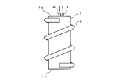
図5は本発明の他の実施形態を示す脱硫器の縦断面図、図6は外観図である。尚、図1及び図2と同一要素には同一符号を付して説明を省略し、異なる要素について説明する。
図5は本発明の他の実施形態を示す脱硫器の縦断面図、図6は外観図である。尚、図1及び図2と同一要素には同一符号を付して説明を省略し、異なる要素について説明する。
本実施形態では、脱硫剤層2昇温用のヒータとして、脱硫剤層2の外周部に配置されるヒータ、すなわち、容器1の外壁に装着される外部ヒータ8を使用する。
本実施形態での、外部ヒータ8は、いわゆる外巻きヒータであり、ヒータ8をコイル状に成形して、容器1の外壁に巻付けてある。
この場合、伝熱フィン10は、燃料通路(脱硫剤層2)の中心部と外周部とを結び方向に延在し、外周側で容器1の壁部を介してヒータ8と熱的に接する。
本実施形態での、外部ヒータ8は、いわゆる外巻きヒータであり、ヒータ8をコイル状に成形して、容器1の外壁に巻付けてある。
この場合、伝熱フィン10は、燃料通路(脱硫剤層2)の中心部と外周部とを結び方向に延在し、外周側で容器1の壁部を介してヒータ8と熱的に接する。
従って、燃料通路(脱硫剤層2)の外周部に配置されるヒータ8の熱が、容器1の外壁を介して直接的に伝熱フィン10に伝わり、この伝熱フィン10は燃料通路の外周部から中心部までこれらを結ぶ方向に延在しているので、ヒータ8の熱が中心部を含む全域に効率良く伝わる。
従って、外周部~中心部の温度差を解消し、中心部を含む全域の脱硫剤を有効に利用でき、結果として脱硫器の寿命を向上させることができる。
従って、外周部~中心部の温度差を解消し、中心部を含む全域の脱硫剤を有効に利用でき、結果として脱硫器の寿命を向上させることができる。
また、本実施形態では、燃料導入口6の設置構造を異ならせてある。すなわち、容器1の天板1b側から上部空間5、脱硫剤層2(及び伝熱フィン10)を貫通する燃料導入管30を設け、その端部を底部空間4に開口させて、燃料導入口6を形成してある。
このようにすることで、脱硫器への燃料配管(燃料供給源からの配管及び改質器への配管)は、燃料導入管30及び燃料導出口7に接続することになるので、天板1b側に統一できる利点がある。
その反面、燃料導入管30を流れる燃料は低温のため、燃料導入管30近傍の脱硫剤の温度が下がってしまう可能性がある。
その反面、燃料導入管30を流れる燃料は低温のため、燃料導入管30近傍の脱硫剤の温度が下がってしまう可能性がある。
そこで、本実施形態では、外部ヒータ8と容器1の壁部を介して接する伝熱フィン10の内側環部又は中央孔部と燃料導入管30とが熱的に接するようにすることで、燃料導入管30近傍の脱硫剤の温度低下を抑制している。
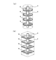
より具体的には、図7及び図8に、伝熱フィン10の構造例1、2を示す。ここでも、容器1が円筒状の場合の例を図7(a)、図8(a)に示し、角筒状の場合の例を図7(b)、図8(b)に示している。
図7の構造例では、伝熱フィン10は、燃料通路(脱硫剤層1)の中心部を貫通する燃料導入管30と接する内側環部11と、外部ヒータ8に容器1の壁部を介して接する外側環部12と、内側環部11と外側環部12とを放射状につなぐ複数のリブ13と、から構成される。従って、複数のリブ13間に前記開口部(図示14)が形成される。
図8の構造例では、伝熱フィン10は、燃料通路(脱硫剤層1)の中心部を貫通する燃料導入管30と接する中央孔部21と、外部ヒータ8に容器1の壁部を介して接する外縁部22とを有する板状体であり、その板面に前記開口部として複数(多数)の孔23が形成される。
尚、以上の実施形態では、脱硫器の容器1を縦置きのアップフロー構造としたが、これに限るものではない。すなわち、縦置きのアップフロー構造は灯油等の液体燃料の脱硫に好適であるが、気体燃料の脱硫の場合には横置きタイプ、すなわち横方向に気体が流れる構造としてもよい。但し、気体燃料の場合であっても、アップフロー若しくはダウンフロー構造とした方が、偏流を起こしにくいため、より好ましい。
また、既に述べたように、脱硫剤の容器1は円筒状としてもよいが、角筒状としてもよく、特に矩形断面の角筒状、すなわち、直方体容器の場合は、燃料電池システムの筐体内での収納スペースを有効利用することができる。
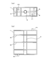
図9は容器形状の他の例として示したもので、(a)は平面視の断面図、(b)は正面視の断面図である。この例では、容器1は扁平な角筒状(細長い矩形断面の角筒状)に形成してあり、容器1の上面と下面とに平面視で対角線方向にずらして開口F1、F2を形成してある。従って、図示のように縦置きにして、ダウンフローとする場合は、上側の開口F1を燃料導入口、下側の開口F2を燃料導出口とすればよい。アップフローとする場合は、下側の開口F2を燃料導入口、上側の開口F1を燃料導出口とすればよい。また、横置きにすることも可能であり、横置きの場合も燃料導入口及び燃料導出口の設定により、ダウンフロー、アップフローのいずれにすることもできる。尚、この例での伝熱フィン10はヒータ3の挿入用筒部に連なって左右に延びるリブ15と、このリブ15に直交する複数のリブ16とから構成されている。
また、以上の実施形態では、容器1内の脱硫剤層2の上下に空間部(上部空間5、下部空間4)を形成したが、これらの空間部を省略することも可能である。例えば、図9では脱硫剤層の図示を省略したが、図9の容器1内の全域に脱硫剤を充填して、空間部を無くすようにしてもよい。
また、容器1については、その周囲を断熱材で覆うことにより、保温性能を向上させることも可能である。
また、容器1については、その周囲を断熱材で覆うことにより、保温性能を向上させることも可能である。
また、図5及び図6の実施形態では、外部ヒータ8は、コイル状に巻付けて装着したが、これに限るものではない。例えば図10に示すように、電熱線を、容器1の外壁に縦方向に沿わせ、その一端側で横方向につながるように、ジグザグ状に配設するようにしてもよい。あるいは、図示は省略するが、コイル状ではなく、独立したリング状の電熱体を用い、これを複数、容器1の外壁に装着するようにしてもよい。また、帯状あるいはシート状の電熱体を用い、これを容器1の外壁に巻付けて装着するようにしてもよい。
次にヒータの配置に関する変形例について説明する。
図11は変形例1を示し、脱硫器を燃料流れ方向から見た概略図である。
この例でのヒータ3は、容器1内の脱硫剤層2の内部に配置されるが、脱硫剤層2の中心からはかなりずれている。
このような場合であっても、ヒータ3に熱的に接し、ヒータ3から脱硫剤層2の外周部へ延在する伝熱フィン10を設けることで、内部温度の均一化を図ることができる。
この例での伝熱フィン10は、模式的に示しているが、ヒータ3を中心として、脱硫剤層2の外周部へ放射状に延在する複数のリブを含んで構成される。そして、複数のリブ間が開口部をなしている。但し、伝熱フィン10の形状はこれに限定されるものではない。
図11は変形例1を示し、脱硫器を燃料流れ方向から見た概略図である。
この例でのヒータ3は、容器1内の脱硫剤層2の内部に配置されるが、脱硫剤層2の中心からはかなりずれている。
このような場合であっても、ヒータ3に熱的に接し、ヒータ3から脱硫剤層2の外周部へ延在する伝熱フィン10を設けることで、内部温度の均一化を図ることができる。
この例での伝熱フィン10は、模式的に示しているが、ヒータ3を中心として、脱硫剤層2の外周部へ放射状に延在する複数のリブを含んで構成される。そして、複数のリブ間が開口部をなしている。但し、伝熱フィン10の形状はこれに限定されるものではない。
図12は変形例2を示し、脱硫器を燃料流れ方向から見た概略図である。
この例での外部ヒータ8は、脱硫剤層2の外周の一部、具体的には、容器1外周の4面のうち、対向する2面に装着している。
このような場合であっても、外部ヒータ8に熱的に接し、脱硫剤層2の外周のヒータ配置側から脱硫剤層2の内部へ延在する伝熱フィン10を設けることで、内部温度の均一化を図ることができる。
この例での伝熱フィン10は、模式的に示しているが、対向するヒータ8を結ぶリブと、これと直交するリブとを含んで、格子状に形成されている。そして、格子間が開口部をなしている。但し、伝熱フィン10の形状はこれに限定されるものではない。
この例での外部ヒータ8は、脱硫剤層2の外周の一部、具体的には、容器1外周の4面のうち、対向する2面に装着している。
このような場合であっても、外部ヒータ8に熱的に接し、脱硫剤層2の外周のヒータ配置側から脱硫剤層2の内部へ延在する伝熱フィン10を設けることで、内部温度の均一化を図ることができる。
この例での伝熱フィン10は、模式的に示しているが、対向するヒータ8を結ぶリブと、これと直交するリブとを含んで、格子状に形成されている。そして、格子間が開口部をなしている。但し、伝熱フィン10の形状はこれに限定されるものではない。
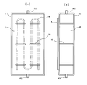
図13は変形例3を示し、(a)は容器の正面視の断面図、(b)は容器の側面視の断面図である。
この例での外部ヒータ8は、脱硫剤層2の外周の一部、具体的には、容器1外周の4面のうち、1面にのみ、装着している。特に、容器1は扁平な角筒状に形成されており、片側の長側面にのみ、外部ヒータ8を外付けしてある。
このような場合であっても、外部ヒータ8に熱的に接し、脱硫剤層2の外周のヒータ配置側から脱硫剤層2の内部へ延在する伝熱フィン10を設けることで、内部温度の均一化を図ることができる。
この例での伝熱フィン10は、脱硫剤層2における燃料の流れ方向に複数設けられ、それぞれの伝熱フィン10は、脱硫剤層2の外周のヒータ配置側から脱硫剤層2の内部を通って脱硫剤層の外周の反対側へ延在している。また、伝熱フィン10は、燃料流れ方向と直交する方向には分断されており、分断された部材間が開口部をなしている。但し、伝熱フィン10の形状はこれに限定されるものではない。
また、図13の脱硫器は、縦置きとしてもよいが、横置きとしてもよい。横置きとする場合、例えば、外部ヒータ8を上面側にして、交換・修理を容易にすることができる。他方、縦置きとする場合は、設置場所の自由度が高く、内部の燃料の流れをアップフロー若しくはダウンフローにすることができる。
この例での外部ヒータ8は、脱硫剤層2の外周の一部、具体的には、容器1外周の4面のうち、1面にのみ、装着している。特に、容器1は扁平な角筒状に形成されており、片側の長側面にのみ、外部ヒータ8を外付けしてある。
このような場合であっても、外部ヒータ8に熱的に接し、脱硫剤層2の外周のヒータ配置側から脱硫剤層2の内部へ延在する伝熱フィン10を設けることで、内部温度の均一化を図ることができる。
この例での伝熱フィン10は、脱硫剤層2における燃料の流れ方向に複数設けられ、それぞれの伝熱フィン10は、脱硫剤層2の外周のヒータ配置側から脱硫剤層2の内部を通って脱硫剤層の外周の反対側へ延在している。また、伝熱フィン10は、燃料流れ方向と直交する方向には分断されており、分断された部材間が開口部をなしている。但し、伝熱フィン10の形状はこれに限定されるものではない。
また、図13の脱硫器は、縦置きとしてもよいが、横置きとしてもよい。横置きとする場合、例えば、外部ヒータ8を上面側にして、交換・修理を容易にすることができる。他方、縦置きとする場合は、設置場所の自由度が高く、内部の燃料の流れをアップフロー若しくはダウンフローにすることができる。
尚、図示の実施形態はあくまで本発明を例示するものであり、本発明は、説明した実施形態により直接的に示されるものに加え、特許請求の範囲内で当業者によりなされる各種の改良・変更を包含するものであることは言うまでもない。
1 容器
2 脱硫剤層
3 ヒータ
4 下部空間
5 上部空間
6 燃料導入口
7 燃料導出口
8 外部ヒータ
10 伝熱フィン
11 内側環部
12 外側環部
13 リブ
14 開口部
15、16 リブ
21 中央孔部
22 外縁部
23 孔
30 燃料導入管
2 脱硫剤層
3 ヒータ
4 下部空間
5 上部空間
6 燃料導入口
7 燃料導出口
8 外部ヒータ
10 伝熱フィン
11 内側環部
12 外側環部
13 リブ
14 開口部
15、16 リブ
21 中央孔部
22 外縁部
23 孔
30 燃料導入管
Claims (12)
- 燃料通路を形成する容器と、前記容器内に充填された脱硫剤による脱硫剤層と、前記脱硫剤層の中心部又は外周部に配置されるヒータと、を含んで構成される脱硫器であって、
前記脱硫剤層の中心部と外周部とを結ぶ方向に延在し、前記ヒータに熱的に接する伝熱フィンを備え、
前記伝熱フィンは、充填する脱硫剤よりも大きな開口部を有することを特徴とする、脱硫器。 - 前記ヒータが前記脱硫剤層の中心部に配置される場合に、前記伝熱フィンは、中心側で前記ヒータに熱的に接し、外周側で前記容器の内壁に熱的に接することを特徴とする請求項1記載の脱硫器。
- 前記伝熱フィンは、前記脱硫剤層の中心部に配置されるヒータと接する内側環部と、前記容器の内壁に接する外側環部と、前記内側環部と前記外側環部とを放射状につなぐ複数のリブと、から構成され、前記複数のリブ間が前記開口部となることを特徴とする請求項2記載の脱硫器。
- 前記伝熱フィンは、前記脱硫剤層の中心部に配置されるヒータと接する中央孔部と、前記容器の内壁に接する外縁部と、を有する板状体であり、その板面に前記開口部として複数の孔を有することを特徴とする請求項2記載の脱硫器。
- 前記ヒータは、前記容器の外壁に装着される外部ヒータであり、前記伝熱フィンは、外周側で前記容器の壁部を介して前記外部ヒータに接することを特徴とする請求項1記載の脱硫器。
- 前記脱硫剤層を貫通してその端部が前記脱硫剤層の上流側に開口する燃料導入管を更に備え、
前記伝熱フィンは、前記燃料導入管と接する内側環部と、前記外部ヒータに前記容器の壁部を介して接する外側環部と、前記内側環部と前記外側環部とを放射状につなぐ複数のリブと、から構成され、前記複数のリブ間が前記開口部となることを特徴とする請求項5記載の脱硫器。 - 前記脱硫剤層を貫通してその端部が前記脱硫剤層の上流側に開口する燃料導入管を更に備え、
前記伝熱フィンは、前記燃料導入管と接する中央孔部と、前記外部ヒータに前記容器の壁部を介して接する外縁部と、を有する板状体であり、その板面に前記開口部として複数の孔を有することを特徴とする請求項5記載の脱硫器。 - 前記伝熱フィンは、前記脱硫剤層における燃料の流れ方向に複数設けられることを特徴とする請求項1記載の脱硫器。
- 燃料通路を形成する容器と、前記容器内に充填された脱硫剤による脱硫剤層と、前記脱硫剤層の内部に配置されるヒータと、を含んで構成される脱硫器であって、
前記ヒータに熱的に接し、前記ヒータから前記脱硫剤層の外周部へ延在する伝熱フィンを備え、
前記伝熱フィンは、充填する脱硫剤よりも大きな開口部を有することを特徴とする脱硫器。 - 前記伝熱フィンは、前記ヒータを中心として前記脱硫剤層の外周部側へ放射状に延在する複数のリブを含んで構成され、前記複数のリブ間が前記開口部となることを特徴とする請求項9記載の脱硫器。
- 燃料通路を形成する容器と、前記容器内に充填された脱硫剤による脱硫剤層と、前記脱硫剤層の外周の一部に配置されるヒータと、を含んで構成される脱硫器であって、
前記ヒータに熱的に接し、前記脱硫剤層の外周のヒータ配置側から前記脱硫剤層の内部へ延在する伝熱フィンを備え、
前記伝熱フィンは、充填する脱硫剤よりも大きな開口部を有することを特徴とする脱硫器。 - 前記伝熱フィンは、前記脱硫剤層の外周のヒータ配置側から前記脱硫剤層の内部を通って前記脱硫剤層の外周の反対側へ延在することを特徴とする請求項11記載の脱硫器。
Priority Applications (1)
| Application Number | Priority Date | Filing Date | Title |
|---|---|---|---|
| JP2013507404A JP5799085B2 (ja) | 2011-03-25 | 2012-03-19 | 脱硫器 |
Applications Claiming Priority (2)
| Application Number | Priority Date | Filing Date | Title |
|---|---|---|---|
| JP2011-067154 | 2011-03-25 | ||
| JP2011067154 | 2011-03-25 |
Publications (1)
| Publication Number | Publication Date |
|---|---|
| WO2012132997A1 true WO2012132997A1 (ja) | 2012-10-04 |
Family
ID=46930729
Family Applications (1)
| Application Number | Title | Priority Date | Filing Date |
|---|---|---|---|
| PCT/JP2012/057025 Ceased WO2012132997A1 (ja) | 2011-03-25 | 2012-03-19 | 脱硫器 |
Country Status (2)
| Country | Link |
|---|---|
| JP (1) | JP5799085B2 (ja) |
| WO (1) | WO2012132997A1 (ja) |
Cited By (2)
| Publication number | Priority date | Publication date | Assignee | Title |
|---|---|---|---|---|
| JP2016137419A (ja) * | 2015-01-26 | 2016-08-04 | 本田技研工業株式会社 | 脱硫器及びこれを組み込む燃料電池システム |
| WO2021099958A1 (en) * | 2019-11-19 | 2021-05-27 | Ceres Intellectual Property Company Limited | Desulfurization unit, sofc system and vehicle |
Citations (8)
| Publication number | Priority date | Publication date | Assignee | Title |
|---|---|---|---|---|
| JPH08217405A (ja) * | 1995-02-10 | 1996-08-27 | Fuji Electric Co Ltd | 燃料電池発電プラント用の燃料改質系反応器 |
| JPH08293315A (ja) * | 1995-04-21 | 1996-11-05 | Toshiba Corp | 燃料電池発電装置用脱硫器 |
| JP2001180910A (ja) * | 1999-12-28 | 2001-07-03 | Daikin Ind Ltd | 選択部分酸化反応装置 |
| JP2004263118A (ja) * | 2003-03-04 | 2004-09-24 | Idemitsu Kosan Co Ltd | 脱硫器及び脱硫方法 |
| JP2007039322A (ja) * | 2005-07-01 | 2007-02-15 | Mitsubishi Heavy Ind Ltd | 改質方法及び改質器 |
| JP2007332318A (ja) * | 2006-06-16 | 2007-12-27 | Idemitsu Kosan Co Ltd | 脱硫器および燃料電池システム |
| JP2008117652A (ja) * | 2006-11-06 | 2008-05-22 | Fuji Electric Holdings Co Ltd | 燃料電池発電用脱硫器 |
| JP2011181270A (ja) * | 2010-02-26 | 2011-09-15 | Jx Nippon Oil & Energy Corp | 燃料電池用脱硫器及びそれを備えた燃料電池システム |
Family Cites Families (2)
| Publication number | Priority date | Publication date | Assignee | Title |
|---|---|---|---|---|
| JPS63246462A (ja) * | 1987-04-01 | 1988-10-13 | Aisan Ind Co Ltd | 蒸発燃料排出防止用キヤニスタ |
| JP5535972B2 (ja) * | 2011-03-25 | 2014-07-02 | Jx日鉱日石エネルギー株式会社 | 脱硫器 |
-
2012
- 2012-03-19 JP JP2013507404A patent/JP5799085B2/ja not_active Expired - Fee Related
- 2012-03-19 WO PCT/JP2012/057025 patent/WO2012132997A1/ja not_active Ceased
Patent Citations (8)
| Publication number | Priority date | Publication date | Assignee | Title |
|---|---|---|---|---|
| JPH08217405A (ja) * | 1995-02-10 | 1996-08-27 | Fuji Electric Co Ltd | 燃料電池発電プラント用の燃料改質系反応器 |
| JPH08293315A (ja) * | 1995-04-21 | 1996-11-05 | Toshiba Corp | 燃料電池発電装置用脱硫器 |
| JP2001180910A (ja) * | 1999-12-28 | 2001-07-03 | Daikin Ind Ltd | 選択部分酸化反応装置 |
| JP2004263118A (ja) * | 2003-03-04 | 2004-09-24 | Idemitsu Kosan Co Ltd | 脱硫器及び脱硫方法 |
| JP2007039322A (ja) * | 2005-07-01 | 2007-02-15 | Mitsubishi Heavy Ind Ltd | 改質方法及び改質器 |
| JP2007332318A (ja) * | 2006-06-16 | 2007-12-27 | Idemitsu Kosan Co Ltd | 脱硫器および燃料電池システム |
| JP2008117652A (ja) * | 2006-11-06 | 2008-05-22 | Fuji Electric Holdings Co Ltd | 燃料電池発電用脱硫器 |
| JP2011181270A (ja) * | 2010-02-26 | 2011-09-15 | Jx Nippon Oil & Energy Corp | 燃料電池用脱硫器及びそれを備えた燃料電池システム |
Cited By (4)
| Publication number | Priority date | Publication date | Assignee | Title |
|---|---|---|---|---|
| JP2016137419A (ja) * | 2015-01-26 | 2016-08-04 | 本田技研工業株式会社 | 脱硫器及びこれを組み込む燃料電池システム |
| WO2021099958A1 (en) * | 2019-11-19 | 2021-05-27 | Ceres Intellectual Property Company Limited | Desulfurization unit, sofc system and vehicle |
| GB2604803A (en) * | 2019-11-19 | 2022-09-14 | Ceres Ip Co Ltd | Desulfurization unit, SOFC system and vehicle |
| GB2604803B (en) * | 2019-11-19 | 2024-02-28 | Ceres Ip Co Ltd | Desulfurization unit, SOFC system and vehicle |
Also Published As
| Publication number | Publication date |
|---|---|
| JPWO2012132997A1 (ja) | 2014-07-28 |
| JP5799085B2 (ja) | 2015-10-21 |
Similar Documents
| Publication | Publication Date | Title |
|---|---|---|
| JP5507119B2 (ja) | 燃料電池システム | |
| JP5372980B2 (ja) | 燃料電池システム | |
| JP5302989B2 (ja) | 燃料電池システム | |
| WO2012164816A1 (ja) | 水素生成装置及び燃料電池システム | |
| JP5799085B2 (ja) | 脱硫器 | |
| JP5927572B2 (ja) | 水添脱硫装置、水素生成装置及び燃料電池システム | |
| JP4990045B2 (ja) | 水素製造装置及び燃料電池システム | |
| WO2015005441A1 (ja) | 燃料電池装置 | |
| JP5895169B2 (ja) | 水素生成装置 | |
| JP5539754B2 (ja) | 燃料電池用脱硫器の加熱方法及び燃料電池システム | |
| JP5535972B2 (ja) | 脱硫器 | |
| JP6893308B2 (ja) | 燃料電池装置 | |
| JP4400922B2 (ja) | 液体燃料用脱硫器 | |
| JP2016115537A (ja) | 燃料電池モジュール | |
| JP6518086B2 (ja) | 燃料電池システム | |
| KR101316042B1 (ko) | 연료전지용 통합형 개질기 시스템 | |
| JP5938580B2 (ja) | 水素生成装置 | |
| WO2012132998A1 (ja) | 脱硫器の温度制御装置、及び、温度制御方法 | |
| JP5535973B2 (ja) | 脱硫器 | |
| KR101943856B1 (ko) | 개질기 | |
| JP2016181369A (ja) | 燃料電池システム | |
| JP2008147087A (ja) | 燃料電池発電システムの液体燃料処理装置 | |
| JP6205581B2 (ja) | 水素生成装置及びそれを用いた燃料電池システム | |
| JP6089210B2 (ja) | 水素生成装置 | |
| JP2010132791A (ja) | 脱硫器およびそれを用いた燃料電池システム |
Legal Events
| Date | Code | Title | Description |
|---|---|---|---|
| 121 | Ep: the epo has been informed by wipo that ep was designated in this application |
Ref document number: 12762863 Country of ref document: EP Kind code of ref document: A1 |
|
| ENP | Entry into the national phase |
Ref document number: 2013507404 Country of ref document: JP Kind code of ref document: A |
|
| NENP | Non-entry into the national phase |
Ref country code: DE |
|
| 122 | Ep: pct application non-entry in european phase |
Ref document number: 12762863 Country of ref document: EP Kind code of ref document: A1 |