WO2012132827A1 - 撮像装置及びその合焦制御方法 - Google Patents
撮像装置及びその合焦制御方法 Download PDFInfo
- Publication number
- WO2012132827A1 WO2012132827A1 PCT/JP2012/056024 JP2012056024W WO2012132827A1 WO 2012132827 A1 WO2012132827 A1 WO 2012132827A1 JP 2012056024 W JP2012056024 W JP 2012056024W WO 2012132827 A1 WO2012132827 A1 WO 2012132827A1
- Authority
- WO
- WIPO (PCT)
- Prior art keywords
- phase difference
- difference detection
- correlation calculation
- amount
- rolling shutter
- Prior art date
- Legal status (The legal status is an assumption and is not a legal conclusion. Google has not performed a legal analysis and makes no representation as to the accuracy of the status listed.)
- Ceased
Links
Images








Classifications
-
- G—PHYSICS
- G02—OPTICS
- G02B—OPTICAL ELEMENTS, SYSTEMS OR APPARATUS
- G02B7/00—Mountings, adjusting means, or light-tight connections, for optical elements
- G02B7/28—Systems for automatic generation of focusing signals
- G02B7/34—Systems for automatic generation of focusing signals using different areas in a pupil plane
-
- H—ELECTRICITY
- H04—ELECTRIC COMMUNICATION TECHNIQUE
- H04N—PICTORIAL COMMUNICATION, e.g. TELEVISION
- H04N23/00—Cameras or camera modules comprising electronic image sensors; Control thereof
- H04N23/60—Control of cameras or camera modules
- H04N23/67—Focus control based on electronic image sensor signals
- H04N23/672—Focus control based on electronic image sensor signals based on the phase difference signals
-
- H—ELECTRICITY
- H04—ELECTRIC COMMUNICATION TECHNIQUE
- H04N—PICTORIAL COMMUNICATION, e.g. TELEVISION
- H04N23/00—Cameras or camera modules comprising electronic image sensors; Control thereof
- H04N23/60—Control of cameras or camera modules
- H04N23/68—Control of cameras or camera modules for stable pick-up of the scene, e.g. compensating for camera body vibrations
- H04N23/689—Motion occurring during a rolling shutter mode
-
- H—ELECTRICITY
- H04—ELECTRIC COMMUNICATION TECHNIQUE
- H04N—PICTORIAL COMMUNICATION, e.g. TELEVISION
- H04N25/00—Circuitry of solid-state image sensors [SSIS]; Control thereof
- H04N25/10—Circuitry of solid-state image sensors [SSIS]; Control thereof for transforming different wavelengths into image signals
- H04N25/11—Arrangement of colour filter arrays [CFA]; Filter mosaics
- H04N25/13—Arrangement of colour filter arrays [CFA]; Filter mosaics characterised by the spectral characteristics of the filter elements
- H04N25/134—Arrangement of colour filter arrays [CFA]; Filter mosaics characterised by the spectral characteristics of the filter elements based on three different wavelength filter elements
-
- H—ELECTRICITY
- H04—ELECTRIC COMMUNICATION TECHNIQUE
- H04N—PICTORIAL COMMUNICATION, e.g. TELEVISION
- H04N25/00—Circuitry of solid-state image sensors [SSIS]; Control thereof
- H04N25/50—Control of the SSIS exposure
- H04N25/53—Control of the integration time
- H04N25/531—Control of the integration time by controlling rolling shutters in CMOS SSIS
-
- H—ELECTRICITY
- H04—ELECTRIC COMMUNICATION TECHNIQUE
- H04N—PICTORIAL COMMUNICATION, e.g. TELEVISION
- H04N25/00—Circuitry of solid-state image sensors [SSIS]; Control thereof
- H04N25/70—SSIS architectures; Circuits associated therewith
- H04N25/703—SSIS architectures incorporating pixels for producing signals other than image signals
- H04N25/704—Pixels specially adapted for focusing, e.g. phase difference pixel sets
-
- G—PHYSICS
- G03—PHOTOGRAPHY; CINEMATOGRAPHY; ANALOGOUS TECHNIQUES USING WAVES OTHER THAN OPTICAL WAVES; ELECTROGRAPHY; HOLOGRAPHY
- G03B—APPARATUS OR ARRANGEMENTS FOR TAKING PHOTOGRAPHS OR FOR PROJECTING OR VIEWING THEM; APPARATUS OR ARRANGEMENTS EMPLOYING ANALOGOUS TECHNIQUES USING WAVES OTHER THAN OPTICAL WAVES; ACCESSORIES THEREFOR
- G03B13/00—Viewfinders; Focusing aids for cameras; Means for focusing for cameras; Autofocus systems for cameras
- G03B13/32—Means for focusing
- G03B13/34—Power focusing
- G03B13/36—Autofocus systems
Definitions
- the present invention relates to an imaging apparatus and a focusing control method thereof.
- the present invention relates to an imaging apparatus and a focusing control method thereof that perform focusing control when imaging a subject.
- an imaging device In recent years, with the increase in resolution of solid-state imaging devices such as CCD (Charge Coupled Device) area sensors and CMOS (Complementary Metal Oxide Semiconductor) image sensors, digital electronic still cameras, digital video cameras, mobile phones, PDAs (Personal Digital Assistants) , Portable information terminals) and other information devices having a photographing function are rapidly increasing.
- An information device having the above imaging function is referred to as an imaging device.
- phase difference AF Auto-Focus
- a readout method in an imaging apparatus using a CMOS is a rolling shutter method in which reset is sequentially performed from above and sequential readout is performed.
- the rolling shutter method since there is a time difference in the readout timing according to the pixel position, in the case of a moving subject, the subject image is distorted.
- Japanese Patent Application Laid-Open No. 2008-72470 and Japanese Patent Application Laid-Open No. 2008-263352 disclose devices that control the charge accumulation timing of pixels for phase difference detection to be the same.
- the phase difference AF is performed only under limited conditions such as depending on the reliability of the focus detection result or when the movement of the subject is not detected. Only the focus detection by the method is performed, and when the focus detection is performed by the phase difference AF method, the influence of the rolling shutter cannot be reduced. Further, the techniques disclosed in Japanese Patent Application Laid-Open No. 2008-72470 and Japanese Patent Application Laid-Open No. 2008-263352 require an additional circuit, which increases the cost.
- an imaging apparatus and a focus control method that can detect the focus position by reducing the influence of the above and accurately control the focus.
- an imaging apparatus wherein a first line in which first phase difference detection pixels on which a light beam that has passed through one side with respect to a main axis of a photographing lens is incident are arranged;
- An imaging device in which a plurality of second lines in which second phase difference detection pixels on which a light beam that has passed through the other side with respect to the main axis of the photographic lens is incident are arranged, and a plurality of such imaging devices, Readout means for reading out signals of phase difference detection pixels arranged on the image sensor in a rolling shutter system, and signals read out from a set of the first phase difference detection pixel and the second phase difference detection pixel
- a set of first correlation calculation means for performing a correlation calculation, a plurality of first phase difference detection pixels arranged on the first line, and a plurality of second arranged on the second line.
- Second correlation calculation means for performing correlation calculation of signals read from one set, and correction for correcting the correlation calculation result by the first correlation calculation means with the correlation calculation result by the second correlation calculation means
- focusing means for controlling focusing using the corrected correlation calculation result.
- the first aspect of the present invention includes a set of a plurality of first phase difference detection pixels arranged on the first line and a plurality of second arrangements arranged on the second line. Correlation calculation of signals read from at least one set of phase difference detection pixels, that is, each signal of a set of phase difference detection pixels on which a light beam passing through the same side with respect to the main axis of the photographing lens is incident The correlation calculation is performed.
- the first aspect of the present invention can determine only the amount of distortion caused by the rolling shutter.
- the first aspect of the present invention corrects the correlation calculation result read from the set of the first phase difference detection pixel and the second phase difference detection pixel, so that the influence of distortion due to the rolling shutter is reduced.
- the focus position can be reduced and the focus position can be detected and the focus control can be performed with high accuracy.
- the second correlation calculation means performs a plurality of sets of correlation calculations
- the correction means performs a correlation calculation result by the first correlation calculation means. May be corrected by an average value of a plurality of sets of correlation calculation results by the second correlation calculation means.
- the second correlation calculation means when the second correlation calculation means performs a correlation calculation of a signal read from a set composed of four or more phase difference detection pixels,
- the four or more phase difference detection pixels may be divided into two groups, and a correlation operation may be performed between an addition signal obtained by adding the detection signals of one group and an addition signal obtained by adding the detection signals of the other group.
- the correlation calculation results of the plurality of sets are compared with each other. If there is a correlation calculation result that differs by a predetermined threshold or more between the comparing means and the comparing means, control is performed so that focusing control is stopped, or reading is performed again after stopping focusing control. And a control means for controlling the focus control to be performed by reading by the means.
- the second correlation calculation means applies the phase difference detection pixel of the set consisting of the first phase difference detection pixel and the second phase difference detection pixel. You may perform the correlation calculation of the signal read from the group of phase difference detection pixels provided with the color filter of the same color as the color filter provided.
- the color provided in the set of phase difference detection pixels including the first phase difference detection pixel and the second phase difference detection pixel. You may make it perform the correlation calculation of the signal read from the group containing the group of the phase difference detection pixel provided with the color filter of the color different from the color of a filter.
- the size of a focal region to be focused the number of phase difference detection pixels for reading a signal used for correlation calculation in the first correlation calculation unit, And further comprising a determination means for determining whether or not to perform correction by the correction means based on at least one of a movement of a subject in a corner and a movement of a subject in the focal region. If it is determined by the determination means that the correction by the correction means is not performed, the correction by the correction means is stopped, and the correlation calculation result of the first correlation calculation means before correction is used. Focusing control may be performed.
- Correlation calculation of signals read from at least one set of pixels that is, correlation calculation of signals of a phase difference detection pixel set where a light beam that has passed through the same side with respect to the main axis of the photographing lens is incident
- the influence of distortion caused by the rolling shutter is reduced and the focus is achieved.
- the position can be detected and focus control can be performed with high accuracy.
- digital camera digital electronic still camera
- the digital camera 10 includes an optical unit 22, a solid-state imaging device 24, and an analog signal processing unit 26.
- the optical unit 22 includes a lens for forming a subject image.
- a solid-state imaging device in this exemplary embodiment, a CMOS (Complementary Metal Oxide Semiconductor)) 24 is disposed behind the optical axis of the lens.
- the analog signal processing unit 26 performs various analog signal processes on the input analog signal.
- the digital camera 10 also performs an analog / digital converter (hereinafter referred to as “ADC”) 28 that converts an input analog signal into digital data, and performs various digital signal processing on the input digital data. And a digital signal processing unit 30.
- ADC analog / digital converter
- the digital signal processing unit 30 includes a line buffer having a predetermined capacity, and also performs control for directly storing the input digital data in a predetermined area of the memory 48 described later.
- the output end of the CMOS 24 is connected to the input end of the analog signal processing unit 26.
- the output terminal of the analog signal processing unit 26 is connected to the input terminal of the ADC 28. Further, the output end of the ADC 28 is connected to the input end of the digital signal processing unit 30. Therefore, the analog signal indicating the subject image output from the CMOS 24 is subjected to predetermined analog signal processing by the analog signal processing unit 26, converted into digital image data by the ADC 28, and then input to the digital signal processing unit 30.
- the digital camera 10 includes a liquid crystal display (hereinafter referred to as “LCD”) 38, an LCD interface 36, a CPU (Central Processing Unit) 40, a memory 48, and a memory interface 46.
- LCD liquid crystal display
- a liquid crystal display (hereinafter referred to as “LCD”) 38 displays a photographed subject image, a menu screen, and the like.
- the LCD interface 36 generates a signal for displaying the subject image, the menu screen, and the like on the LCD 38 and supplies the signal to the LCD 38.
- a CPU (Central Processing Unit) 40 controls the operation of the entire digital camera 10.
- the memory 48 temporarily stores digital image data obtained by photographing.
- the memory interface 46 controls access to the memory 48.
- the digital camera 10 includes an external memory interface 50 for enabling the portable memory card 52 to be accessed by the digital camera 10, and a compression / decompression processing circuit 54 for performing compression processing and decompression processing on the digital image data. It is configured to include.
- a flash memory is used as the memory 48, and an xD picture card (registered trademark) is used as the memory card 52.
- the memory 48 is not limited to this.
- the digital signal processing unit 30, the LCD interface 36, the CPU 40, the memory interface 46, the external memory interface 50, and the compression / decompression processing circuit 54 are connected to each other via a system bus BUS. Therefore, the CPU 40 controls the operation of the digital signal processing unit 30 and the compression / decompression processing circuit 54, displays various information via the LCD interface 36 to the LCD 38, and the memory interface 46 or the external memory interface to the memory 48 and the memory card 52. 50 can be accessed.
- the digital camera 10 includes a timing generator 32 that mainly generates a timing signal (pulse signal) for driving the CMOS 24 and supplies the timing signal to the CMOS 24.
- the driving of the CMOS 24 is controlled by the CPU 40 via the timing generator 32.
- the CMOS 24 includes a plurality of lines in which a plurality of pixels are arranged in the horizontal direction, and is controlled by a rolling shutter system that controls exposure start timing and readout timing for each pixel on the line.
- a rolling shutter system that controls exposure start timing and readout timing for each pixel on the line.
- the digital camera 10 is provided with a motor drive unit 34, and driving of a focus adjustment motor, a zoom motor, and an aperture drive motor (not shown) provided in the optical unit 22 is also controlled by the CPU 40 via the motor drive unit 34.
- the motor drive unit 34 driving of a focus adjustment motor, a zoom motor, and an aperture drive motor (not shown) provided in the optical unit 22 is also controlled by the CPU 40 via the motor drive unit 34.
- the lens according to the exemplary embodiment includes a photographing lens including a zoom lens and a focus lens, and includes a lens driving mechanism (not shown).
- the lens drive mechanism includes the focus adjustment motor, the zoom motor, and the aperture drive motor, and these motors are each driven by a drive signal supplied from the motor drive unit 34 under the control of the CPU 40.
- the digital camera 10 is provided with an operation unit 56 that includes various switches such as a release switch (so-called shutter), a power switch, a mode switch, a menu switch, a decision switch, and a cancel switch.
- a release switch (so-called shutter) is pressed when performing shooting.
- the power switch is operated when the digital camera 10 is turned on / off.
- the mode changeover switch is operated when setting any one of a shooting mode that is a mode for performing shooting and a playback mode that is a mode for playing back a subject image on the LCD 38.
- the menu switch is pressed when a menu screen is displayed on the LCD 38.
- the determination switch is pressed when confirming the content of the previous operation.
- the cancel switch is pressed when canceling the previous operation content.
- the release switch of the digital camera 10 is pressed down to the intermediate position (hereinafter referred to as “half-pressed state”) and to the final pressed position beyond the intermediate position.
- a two-stage pressing operation of a state (hereinafter referred to as a “fully pressed state”) can be detected.
- the AF function is activated after the AE (Automatic Exposure) function is set by setting the release switch halfway and the exposure state (shutter speed, aperture state) is set. Focus control is performed.
- exposure photographing is performed when the digital camera 10 is fully pressed thereafter.
- the digital camera 10 has a strobe 44 that emits light to irradiate the subject as necessary at the time of shooting, and is interposed between the strobe 44 and the CPU 40, and power for causing the strobe 44 to emit light under the control of the CPU 40. And a charging unit 42 for charging the battery. Further, the strobe 44 is also connected to the CPU 40, and the light emission of the strobe 44 is controlled by the CPU 40.
- FIG. 2 is a plan view showing the entire configuration of the CMOS 24.
- CMOS 24 In the imaging area 70 of the CMOS 24, a large number of pixels (light receiving elements: photodiodes; not shown) are arranged in a two-dimensional array.
- a so-called honeycomb pixel array is formed in which even-numbered pixel rows are shifted by 1 ⁇ 2 pixel pitch with respect to odd-numbered pixel rows.
- R red
- G green
- B blue
- the color filters are stacked in a state of being arranged in a Bayer array.
- the RGB arrangement may be a stripe arrangement.
- the CMOS 24 is further provided with horizontal scanning circuits 72 1 and 74 2 and vertical scanning circuits 74 1 and 74 2 .
- horizontal signal lines are connected to the horizontal scanning circuits 72 1 and 74 2
- vertical selection lines are connected to the vertical scanning circuits 74 1 and 74 2 .
- the vertical scanning circuit 74 1, through vertical selection lines, for selecting each pixel of the first pixel group of odd rows which are arranged in the imaging area 70 in the row (line) basis. In this case, the lines are selected one by one from the bottom end, and pixel signals are read collectively for each line. Note that a CDS circuit that performs correlated double sampling processing on each pixel signal read from the first pixel group in units of rows to reduce reset noise may be provided.
- the horizontal scanning circuit 72 1, the pixel signals for one line read from the first pixel group are selected sequentially pixels from the left end. Thereby, each pixel signal read from the first pixel group is output to the horizontal signal line.
- the pixel signals sequentially output to the horizontal signal lines are amplified by a subsequent amplifier (not shown) and then output to the outside.
- the vertical scanning circuit 74 through the vertical selection line, selects each pixel in the second pixel group of even rows which are arranged in the imaging area 70 in units of rows. In this case, the lines are selected one by one from the bottom end, and pixel signals are read collectively for each line.
- a CDS circuit that performs correlated double sampling processing on each pixel signal read out from the second pixel group in units of rows to reduce reset noise may be provided.
- the horizontal scanning circuit 72 2 the one row pixel signals output from the second pixel group are selected sequentially pixels from the left end. Thereby, each pixel signal read from the second pixel group is output to the horizontal signal line.
- the pixel signals sequentially output to the horizontal signal lines are amplified by a subsequent amplifier (not shown) and then output to the outside.
- a rectangular phase difference detection area is provided in a part of the imaging area 70, for example, in the center position. It should be noted that the phase difference detection area may be provided only at one position relative to the imaging area 70, or may be provided at a plurality of positions so that AF can be performed anywhere within the imaging area 70.
- FIG. 3 is a schematic enlarged view of a part of the surface within the phase difference detection region.
- FIG. 3 illustrates a state in which lines (here, odd rows) in which the phase difference detection pixels 1x are arranged and lines (in this case, even rows) in which the phase difference detection pixels 1y are arranged are alternately arranged. .
- lines here, odd rows
- lines in this case, even rows
- a so-called honeycomb array is formed in which even-numbered pixel rows are shifted by 1/2 pixel pitch with respect to odd-numbered pixel rows.
- FIG. 3 shows a state in which only the phase difference detection pixels 1x and 1y are arranged. However, some of the imaging pixels (pixels other than the phase difference detection pixels 1x and 1y and a light shielding film) are illustrated. May be provided, and normal pixels for capturing a subject image) may be disposed. Further, only the imaging pixels are arranged in the imaging area 70 other than the phase difference detection area (not shown).
- each pixel is indicated by R (red), G (green), and B (blue).
- R, G, and B represent the colors of the color filters stacked on each pixel.
- the color filters are Bayer-arrayed for odd-numbered pixels and the color filters are Bayer-arrayed for even-numbered pixels.
- the phase difference detection pixels 1x and 1y have the light shielding film openings 2x and 2y formed smaller than the imaging pixel, and the light shielding film opening 2x of the pixel 1x is provided eccentrically in the left direction, and the light shielding film opening of the pixel 1y. 2y is eccentrically provided in the right direction (phase difference detection direction).
- the phase difference detection pixel 1x is incident with a light beam that has passed through one side (here, the left side) with respect to the main axis of the photographing lens.
- the phase difference detection pixel 1y is disposed on a line adjacent to the pair of phase difference detection pixels 1x, and a light beam that has passed through the other side (here, the right side) is incident on the main axis of the photographing lens. .
- this shift amount phase difference amount
- phase difference detection may be performed using only a specific color phase difference detection pixel pair.
- the phase difference detection may be performed using a specific phase difference detection pixel pair in the phase difference detection pixel pair.
- the phase difference detection pixels 1x and 1y can also be used for forming a subject image.
- FIG. 4 is an explanatory diagram for explaining a phase difference detection method in the case where adjacent phase difference detection pixels 1x and 1y provided with a G color filter are used as a pair for phase difference detection for subject distance measurement.
- a curve X shown in the lower part of FIG. 4 is a graph in which the detection signal amounts of the G phase difference detection pixels 1x arranged in a horizontal row are plotted.
- a curve Y is a graph in which the detection signal amount of the G phase difference detection pixel 1y paired with the pixel 1x is plotted.
- the pair of phase difference detection pixels 1x and 1y are adjacent pixels and are very close to each other, and thus are considered to receive light from the same subject. For this reason, if there is no influence of distortion caused by a rolling shutter, which will be described later, the curve X and the curve Y are considered to have substantially the same shape, and the deviation in the left-right direction (phase difference detection direction) is a pair of phase differences obtained by pupil division This is the amount of phase difference between the image viewed at one pixel 1x of the detection pixels and the image viewed at the other pixel 1y.
- a lateral shift amount (phase difference amount) can be obtained, and a distance to the subject can be calculated based on the phase difference amount.
- a known method for example, a method described in Japanese Patent Application Laid-Open No. 2010-8443 or a method described in Japanese Patent Application Laid-Open No. 2010-91991 is adopted as a method for obtaining the evaluation value of the correlation amount between the curve X and the curve Y. It ’s fine.
- the integrated value of the absolute value of the difference between each point X (i) constituting the curve X and each point Y (i + j) constituting the curve Y is used as the evaluation value, and the j value giving the maximum evaluation value is expressed as the phase difference. Amount.
- the motor driving unit 34 is controlled to drive the focus adjustment motor of the optical unit 22 to control the focus lens position, thereby focusing on the subject.
- CMOS controlled by a rolling shutter system is used as the solid-state imaging device. Therefore, when the correlation calculation is performed using the detection signal acquired from the phase difference detection pixel pair including the two phase difference detection pixels whose readout timings are not the same, the subject image moves or changes during this timing shift. Then, the captured subject image is distorted, and the influence (distortion amount) of the distortion caused by the rolling shutter is generated on the phase difference amount obtained by the correlation calculation (see also FIG. 5A).
- phase difference detection pixels 1x (indicated by phase difference detection pixels A and A ′ in FIG. 5B) having the same distance (horizontal position) from one end of the line are 1
- the phase difference detection pixels A and A ′ have the same eccentric direction of the light shielding film opening (pass the same side with respect to the main axis of the photographing lens).
- the incident light flux From this, this exemplary embodiment can calculate only the amount of distortion due to the rolling shutter.
- AF control is performed by correcting the phase difference amount calculated by the normal phase difference detection pixel pair using the detection signals from the pair of phase difference detection pixels.
- phase difference detection pixels a pair consisting of the phase difference detection pixels 1x and 1y
- phase difference detection pixels a pair of phase difference detection pixels that are obliquely adjacent and detect a phase difference for subject distance measurement
- a pair of phase difference detection pixels a pair of two phase difference detection pixels 1x arranged on the odd rows or two phase difference detections arranged on the even rows for detecting the amount of distortion caused by the rolling shutter
- the pair of pixels 1y is referred to as a rolling detection pixel pair in order to distinguish it from the phase difference detection pixel pair.
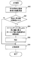
- FIG. 6 is a flowchart showing the flow of AF control according to the present exemplary embodiment.
- a detection signal (hereinafter referred to as a phase difference detection pixel signal) read from each of the phase difference detection pixels constituting a phase difference detection pixel pair composed of predetermined phase difference detection pixels 1x and 1y that are obliquely adjacent to each other.
- the phase difference amount is obtained by performing a correlation calculation. For example, in the example shown in FIG. 7, diagonal lines are given to the pixels constituting the phase difference detection pixel pair (the same applies to FIGS. 8 to 12 described later). Specifically, each of a pair of phase difference detection pixels 1x and 1y provided with diagonally adjacent G color filters in the seventh and eighth rows is used as a phase difference detection pixel pair.
- step 102 a correlation calculation is performed on detection signals (hereinafter also referred to as rolling detection pixel signals) read from each of the phase difference detection pixels constituting the rolling detection pixel pair, and the amount of distortion caused by the rolling shutter is calculated.
- detection signals hereinafter also referred to as rolling detection pixel signals
- a combination with the phase difference detection pixel 1x that is arranged and provided with the color filter of the same color may be a rolling detection pixel pair.
- a combination with the phase difference detection pixel 1y that is arranged and provided with the color filter of the same color may be a rolling detection pixel pair.
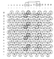
- FIG. 7 an example of the pixels constituting the rolling detection pixel pair is indicated by a thick line (the same applies to FIGS. 8 to 12 described later). Specifically, it is a combination of each of the G-color phase difference detection pixels 1x in the seventh row and the G-color phase difference detection pixels 1x in the eleventh row, and is a distance from one end of each line, that is, horizontal. Pixels having the same position in the direction are set as a rolling detection pixel pair.
- a rolling detection pixel pair including a phase difference detection pixel 1x in the seventh row and the third column and a phase difference detection pixel 1x in the eleventh row and the third column, and the seventh row and the seventh column.
- Rolling detection pixel pair composed of the phase difference detection pixel 1x of the eye and the phase difference detection pixel 1x of the 11th row and the 7th column, the phase difference detection pixel 1x of the 7th row and the 11th column, and the 11th row and the 11th column
- a rolling detection pixel pair composed of the phase difference detection pixel 1x of the eye, a phase difference detection pixel 1x of the seventh row and the 15th column and a phase difference detection pixel 1x of the 11th row and the 15th column.
- the correlation calculation of each detection signal of the pixel pair is performed, and the amount of distortion obtained by this correlation calculation is multiplied by 1 ⁇ 4 to determine the amount of distortion due to the rolling shutter.
- the vertical separation distance of each pixel of the rolling detection pixel pair is four times the vertical separation distance of each pixel of the phase difference detection pixel pair, and reading takes four times as long.
- the amount of distortion due to the rolling shutter is calculated using a group of G pixels in the seventh row and the eleventh row (a group of G phase difference detection pixels 1x).
- the amount of distortion due to the rolling shutter may be calculated using the G pixels in the 7th and 15th rows. In this case, it is necessary to multiply the correlation calculation result of the rolling detection pixel signal by 1/8.
- the distortion amount due to the rolling shutter may be calculated using a set of G pixels in the 8th and 12th rows (a set of G phase difference detection pixels 1y).
- step 104 the amount of phase difference obtained in step 100 is corrected by subtracting the amount of distortion caused by the rolling shutter obtained in step 102 from the amount of phase difference obtained in step 100.
- step 106 focusing control is performed as described above based on the corrected phase difference amount.
- the method for calculating the distortion amount by the rolling shutter is not limited to the example described with reference to FIG.
- distortion amounts due to a plurality of rolling shutters may be calculated and averaged to obtain a final distortion amount due to the rolling shutter, which may be used for correction.
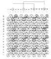
- a correlation calculation of the detection signals read from the rolling detection pixel pair shown in FIG. 7 is performed to obtain a distortion amount by the rolling shutter (this is referred to as a distortion amount by the first rolling shutter).
- a distortion amount by the first rolling shutter this is referred to as a distortion amount by the first rolling shutter.
- a rolling detection pixel pair composed of a phase difference detection pixel 1y in the eighth row and the fourth column and a phase difference detection pixel 1y in the twelfth row and the fourth column, eight rows Rolling detection pixel pair composed of the phase difference detection pixel 1y in the eighth column and the phase difference detection pixel 1y in the twelfth row, the eighth column, the phase difference detection pixel 1y in the eighth row and the twelfth column, and 12 rows It consists of a rolling detection pixel pair composed of the phase difference detection pixel 1y in the 12th column, a phase difference detection pixel 1y in the 8th row and 16th column, and a phase difference detection pixel 1y in the 12th row and 16th column.
- Rolling detection pixel pair Each may perform the correlation calculation of the detection signals read out from. Further, in this method, the amount of distortion caused by the first rolling shutter and the amount of distortion caused by the second rolling shutter are calculated so as to obtain the amount of distortion caused by the rolling shutter (this is called the amount of distortion caused by the second rolling shutter). An average value may be obtained and this average value may be used for correction in step 104. Thereby, the calculation accuracy of the amount of distortion by the rolling shutter is increased, and the accuracy of AF control is improved.
- the amount of distortion by two rolling shutters is calculated and averaged and used for correction.
- the distortion amount by three or more rolling shutters may be calculated and averaged and used for correction.
- the digital camera 10 may be provided with a “normal shooting” mode and a “pixel addition shooting” mode.
- a “normal shooting” mode a high-definition image of the subject is generated from each of the output signals of all pixels.
- pixel addition imaging high-sensitivity imaging is performed instead of lowering the resolution by adding signals of a plurality of pixels such as 2-pixel addition or 4-pixel addition to the output signals of all pixels.
- Which shooting is performed is performed by switching drive pulses supplied from the timing generator 32 to the solid-state imaging device (CMOS) 24.
- CMOS solid-state imaging device
- the resolution of the subject image is 1 ⁇ 4 of the number of pixels of the solid-state imaging device, but the exposure amount is four times. For this reason, it is possible to obtain a high S / N image even in a dark scene.
- the AF control may be performed according to the shooting mode. That is, an addition signal obtained by adding detection signals of a plurality of phase difference detection pixels 1x having the same distance from one end of the line and a detection signal of a plurality of phase difference detection pixels 1y having the same distance from one end of the line are added.
- the phase difference amount can be obtained by performing a correlation operation with the addition signal.
- adding detection signals from a plurality of pixels having the same distance from one end of a line may be referred to as vertical addition.
- an addition signal obtained by adding the detection signals of the G phase difference detection pixels 1x in the third, seventh, eleventh, and fifteenth rows and the G color in the fourth, eighth, twelfth, and sixteenth rows is performed.
- a correlation calculation with the addition signal obtained by adding the detection signal of the phase difference detection pixel 1y is performed to obtain a phase difference amount, and AF control is performed. Even in this case, the distortion amount due to the rolling shutter can be calculated and corrected.
- the G phase detection pixels 1x in the 7th and 11th rows but also the G phase difference detection pixels 1x in the 3rd and 15th rows are used in combination.
- an addition signal a obtained by adding the detection signal of the G-color phase difference detection pixel 1x in the third row and the detection signal of the G-color phase difference detection pixel 1x in the eleventh row is expressed in the horizontal direction.
- the sum signal b obtained by adding the detection signal of the G-color phase difference detection pixel 1x in the seventh row and the detection signal of the G-color phase difference detection pixel 1x in the 15th row in the horizontal direction is obtained for each pixel having the same position. May be obtained for each pixel having the same position, and a correlation operation between the addition signals a and b for pixels having the same horizontal position may be performed to obtain the amount of distortion due to the rolling shutter.
- the signal S / N increases, and the accuracy of calculating the amount of distortion by the rolling shutter is improved.
- the horizontal position of the addition signal c obtained by adding the detection signal of the G color phase difference detection pixel 1y in the fourth row and the detection signal of the G color phase difference detection pixel 1y in the twelfth row is equal. Obtained for each pixel.
- an added signal d obtained by adding the detection signal of the G-color phase difference detection pixel 1y in the eighth row and the detection signal of the G-color phase difference detection pixel 1y in the sixteenth row has the same horizontal position. Obtained for each pixel.
- a correlation operation between the addition signals c and d for the pixels having the same horizontal position is performed, a distortion amount by the rolling shutter is obtained, and an average value of the distortion amount by the rolling shutter obtained from the addition signal ab is obtained. May be obtained as a distortion amount by the final rolling shutter.
- the amount of distortion due to the rolling shutter can be obtained by vertical addition using pixels of different colors (not shown).
- an addition signal e obtained by adding the detection signal of the R phase difference detection pixel 1x in the fifth row and the detection signal of the G phase difference detection pixel 1x in the seventh row is set in the horizontal direction. It calculates
- an addition signal f obtained by adding the detection signal of the G-color phase difference detection pixel 1x in the seventh row and the detection signal of the R-color phase difference detection pixel 1x in the ninth row is set for each pixel having the same horizontal position.
- the distortion amount by the rolling shutter may be obtained by calculating the correlation between the addition signals e and f for the pixels having the same horizontal position.
- an addition signal e obtained by adding the detection signal of the R phase difference detection pixel 1x in the fifth row and the detection signal of the G phase difference detection pixel 1x in the seventh row is set in the horizontal direction. It calculates
- an addition signal f obtained by adding the detection signal of the G-color phase difference detection pixel 1x in the seventh row and the detection signal of the R-color phase difference detection pixel 1x in the ninth row is set for each pixel having the same horizontal position. Ask for.
- correlation calculation is performed on the addition signals e and f for pixels having the same horizontal position to obtain the amount of distortion by the rolling shutter (this is referred to as the amount of distortion by the first rolling shutter), and the sixth line.
- An addition signal g obtained by adding the detection signal of the R phase difference detection pixel 1y and the detection signal of the G color phase difference detection pixel 1y in the eighth row is obtained for each pixel having the same horizontal position.
- an addition signal h obtained by adding the detection signal of the G-color phase difference detection pixel 1y in the eighth row and the detection signal of the R-color phase difference detection pixel 1y in the tenth row is set for each pixel having the same horizontal position. Ask for.
- the correlation calculation of the addition signals g and h for pixels having the same horizontal position is performed to determine the amount of distortion caused by the rolling shutter (this is referred to as the amount of distortion caused by the second rolling shutter). Further, the average value of the distortion amount due to the first rolling shutter and the distortion amount due to the second rolling shutter is obtained as the final distortion amount due to the rolling shutter, and is used for correcting the phase difference amount.
- distortion amounts due to a plurality of rolling shutters obtained from detection signals of a plurality of rolling detection pixel pairs of different colors arranged in the same position in the vertical direction can be averaged and used.
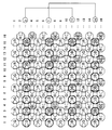
- FIGS. 10, 11, and 12. 10 11, and 12, as in FIGS. 7, 8, and 9 pixels with diagonal lines are pixels used to calculate the phase difference amount used for distance measurement, Pixels drawn with bold lines are pixels used to calculate the amount of distortion by the rolling shutter.
- phase difference amount is obtained by using the G phase difference detection pixel 1x in the seventh row and the phase difference detection pixel 1y in the eighth row as a phase difference detection pixel pair
- the amount of distortion by the rolling shutter obtained by the correlation calculation of the G color detection signals in the eleventh row and the amount of distortion by the rolling shutter obtained by the correlation calculation of the B pixels in the seventh row and the eleventh row are averaged.
- a distortion amount due to a simple rolling shutter may be obtained and used for correcting the phase difference amount.
- the amount of distortion by the rolling shutter obtained by the correlation calculation of the G color detection signals of the 7th and 11th rows, and the amount of distortion by the rolling shutter obtained by the correlation operation of the B pixel detection signals of the 7th and 11th rows. are averaged to determine the amount of distortion caused by the first rolling shutter. Further, the amount of distortion by the rolling shutter obtained by the correlation calculation of the G color detection signals in the 8th and 12th rows and the rolling shutter obtained by the correlation calculation of the B pixel detection signals in the 8th and 12th rows.
- the distortion amount by the second rolling shutter is obtained by averaging the distortion amounts. Then, an average value of the distortion amount due to the first rolling shutter and the distortion amount due to the second rolling shutter may be obtained as the final distortion amount due to the rolling shutter, and this may be used for correcting the phase difference amount.
- the detection signal of the G-color phase difference detection pixel 1x in the third row and the G-color in the eleventh row An addition signal k obtained by adding the detection signals of the phase difference detection pixels 1x is obtained for each pixel having the same horizontal position.
- correlation calculation is performed on the addition signals k and l for pixels having the same horizontal position, and the amount of distortion due to the first rolling shutter is obtained.
- an addition signal m obtained by adding the detection signal of the B color phase difference detection pixel 1x in the third row and the detection signal of the B color phase difference detection pixel 1x in the eleventh row is set for each pixel having the same horizontal position. Pixels obtained by adding the detection signal of the B phase difference detection pixel 1x in the seventh row and the detection signal of the B phase difference detection pixel 1x in the fifteenth row to the same horizontal position. Ask every time. Furthermore, the correlation calculation of the addition signals m and n is performed for the pixels having the same horizontal position, and the distortion amount due to the second rolling shutter is obtained. Then, an average value of the distortion amount by the first rolling shutter and the distortion amount by the second rolling shutter may be obtained as the final distortion amount by the rolling shutter, and this may be used for correcting the phase difference amount.
- a pixel in which the horizontal position is equal to the addition signal q obtained by adding the detection signal of the G color phase difference detection pixel 1y in the eighth row and the detection signal of the G color phase difference detection pixel 1y in the sixteenth row It is calculated every time, and the correlation calculation of the addition signals p and q for the pixels having the same horizontal position is performed to determine the distortion amount due to the third rolling shutter.
- a pixel in which the horizontal position is equal to the addition signal r obtained by adding the detection signal of the B phase difference detection pixel 1y in the fourth row and the detection signal of the B phase difference detection pixel 1y in the twelfth row The horizontal position of the sum signal s obtained by adding the detection signal of the B-color phase difference detection pixel 1y in the 8th row and the detection signal of the B-color phase difference detection pixel 1y in the 16th row is the same. Obtained for each pixel. Further, the correlation calculation of the addition signals r and s for the pixels having the same horizontal position is performed to determine the distortion amount due to the fourth rolling shutter.
- an average value of the distortion amount by the third rolling shutter and the distortion amount by the fourth rolling shutter is set as a distortion amount B by the rolling shutter. Then, an average value of the distortion amount A by the rolling shutter and the distortion amount B by the rolling shutter may be obtained as a final distortion amount by the rolling shutter, and this may be used for correcting the phase difference amount.
- the rolling correction is always performed.
- the present invention is not limited to this.
- There may be provided a switching means for switching between and AF control according to the mode switched by the user by the switching means.
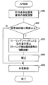
- the amount of distortion due to the rolling shutter varies depending on the movement of the subject and the change in the angle of view, and is not necessarily constant. Therefore, as described above with reference to FIG. 8 and FIGS. 10 to 12, when the distortion amounts due to the plurality of rolling shutters are averaged to calculate the final distortion amount due to the rolling shutters, the plurality of rolling shutters. If the amount of distortion differs greatly, it may be determined that the movement of the subject or the angle of view has suddenly changed, and the AF operation may be stopped. Hereinafter, this control will be described in detail. Note that the configuration of the digital camera 10 of the present exemplary embodiment is the same as that of the first exemplary embodiment, and thus description thereof is omitted.
- step 110 as described in the first exemplary embodiment, correlation calculation of the phase difference detection pixel signal is performed to obtain the phase difference amount.
- step 112 as described with reference to FIGS. 8 and 10 to 12 in the first exemplary embodiment, the amount of distortion caused by a plurality of rolling shutters is obtained and averaged to obtain the amount of distortion caused by the final rolling shutter. Ask for. Note that the distortion amounts calculated by the plurality of rolling shutters before calculating the final rolling shutter distortion amount are stored in a predetermined storage unit until the determination in step 114 below is completed.
- step 114 the distortion amounts by a plurality of rolling shutters (excluding the distortion amount by the final rolling shutter) stored in the storage means are compared with each other, and it is determined whether or not there is one whose difference is equal to or greater than a threshold value. To do. If a negative determination is made here, the process proceeds to step 116, where the amount of distortion caused by the rolling shutter finally obtained is subtracted from the amount of phase difference obtained in step 110 for correction. In step 118, focusing control is performed based on the corrected phase difference amount.
- step 114 if an affirmative determination is made in step 114, the process proceeds to step 120, error processing is performed, and this AF control is terminated.
- the error process is, for example, displaying an error message.
- the AF control may be re-executed after the AF control is finished once.
- the AF control routine is terminated before the focus control, so that erroneous focus can be prevented.
- the final distortion amount by the rolling shutter is obtained before the determination in step 114, but after the negative determination is made in step 114, the final distortion amount by the rolling shutter is obtained and corrected. It may be used.
- the rolling correction is performed.
- a switching means for switching between the second mode and the switching mode may be provided, and AF control may be performed according to the mode switched by the user using the switching means.
- the amount of distortion caused by the rolling shutter is always calculated and corrected during AF control.
- the rolling shutter is used. The process of calculating and correcting the distortion amount may be omitted. This will be described in detail below.
- the configuration of the digital camera 10 of the present exemplary embodiment is the same as that of the first exemplary embodiment, and thus description thereof is omitted.
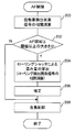
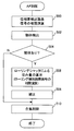
- FIG. 14 is a flowchart showing an example of the flow of AF control processing according to the present exemplary embodiment.
- step 200 as described in the first exemplary embodiment, the correlation calculation of the phase difference detection pixel signal is performed to obtain the phase difference amount.
- step 202 it is determined whether or not the AF area is larger than a predetermined threshold value.
- the AF area is an area to be focused, and when the digital camera 10 is configured so that the position and size can be arbitrarily set by the user, or in the AF area depending on the shooting mode. In some cases, the size may be set. In the present exemplary embodiment, information on the size of the AF area set in the digital camera 10 is acquired and compared with a predetermined threshold value.
- step 204 the correlation calculation of the rolling detection pixel signal is performed as described in the first exemplary embodiment, and the distortion amount due to the rolling shutter is obtained.
- step 206 the phase difference amount obtained in step 200 is corrected by subtracting the amount of distortion caused by the rolling shutter obtained in step 204 from the phase difference amount obtained in step 200.
- step 208 focusing control is performed based on the corrected phase difference amount.
- step 208 focusing control is performed using the phase difference amount obtained in step 200 (a phase difference amount not corrected by the distortion amount by the rolling shutter) as it is.
- the AF area is not so large, the number of phase difference detection pixels for detecting the phase difference for distance measurement is reduced, and the influence of distortion due to the rolling shutter is considered to be small. Therefore, in this example, if the AF area is less than the threshold value, the AF control is performed without calculating and correcting the distortion amount by the rolling shutter. Thereby, the time required for AF control can be shortened.
- FIG. 15 is a flowchart showing another example of the flow of AF control processing.
- step 300 as described in the first exemplary embodiment, the correlation calculation of the phase difference detection pixel signal is performed to obtain the phase difference amount.
- step 302 it is determined whether or not the number of read pixels (the number of phase difference detection pixels used for calculating the phase difference amount in step 300) is equal to or greater than a predetermined threshold value. If the determination in step 302 is affirmative, in step 304, correlation calculation of the rolling detection pixel signal is performed as described in the first exemplary embodiment to obtain the amount of distortion due to the rolling shutter. In step 306, the amount of distortion due to the rolling shutter obtained in step 304 is subtracted from the phase difference obtained in step 300 to correct the phase difference obtained in step 300. In step 308, focusing control is performed based on the corrected phase difference amount.
- step 308 focusing control is performed using the phase difference amount obtained in step 300 (phase difference amount not corrected by the distortion amount by the rolling shutter) as it is.
- the AF control is performed without calculating and correcting the distortion amount by the rolling shutter. Thereby, the time required for AF control can be shortened.
- the threshold value may be changed according to the angle of view. More specifically, for example, if the digital camera 10 can be switched to a wide (wide angle) mode, a standard mode, and a tele (telephoto) mode, a threshold value is set in advance for each mode, and AF control is performed. The threshold value may be changed according to the shooting mode at the time. Note that it is presumed that the influence of distortion caused by the rolling shutter increases as the angle of view is on the tele side. Therefore, the tele side threshold may be set smaller than that on the wide side.
- FIG. 16 is a flowchart showing another example of the flow of AF control processing.
- step 400 as described in the first exemplary embodiment, the correlation calculation of the phase difference detection pixel signal is performed to obtain the phase difference amount.
- step 402 it is determined whether or not the subject distance is greater than or equal to a threshold value.
- the object distance provisionally obtained from the phase difference obtained in step 400 is compared with a predetermined threshold value.
- the threshold value to be compared here is changed according to the size of the AF area or the number of readout pixels. If an affirmative determination is made in step 402, then in step 404, correlation calculation of the rolling detection pixel signal is performed as described in the first exemplary embodiment, and the amount of distortion due to the rolling shutter is obtained.
- step 406 the amount of distortion due to the rolling shutter obtained in step 406 is subtracted from the amount of phase difference obtained in step 400 to correct the phase difference obtained in step 400.
- focusing control is performed based on the corrected phase difference amount.
- step 408 focusing control is performed using the phase difference amount obtained in step 400 (a phase difference amount that is not corrected by the amount of distortion by the rolling shutter) as it is.
- ⁇ ⁇ Rolling changes the degree of influence depending on the movement of the subject within the shooting angle of view.
- the longer the subject distance the greater the influence of distortion caused by the rolling shutter. Therefore, in this example, when the subject distance is longer than the threshold, the distortion amount is calculated and corrected by the rolling shutter, and when the subject distance is shorter than the threshold, the distortion amount is not calculated and corrected by the rolling shutter. I made it.
- FIG. 17 is a flowchart showing another example of the flow of AF control processing.
- step 500 as described in the first exemplary embodiment, the correlation calculation of the phase difference detection pixel signal is performed to obtain the phase difference amount.
- step 502 the moving object within the angle of view is detected.
- a known motion vector may be calculated between past image data stored in the memory 48 and current image data, and detected based on the magnitude of the motion vector.
- step 504 based on the detection result, it is determined whether or not a moving object exists within the angle of view. If an affirmative determination is made in step 402, then in step 506, correlation calculation of the rolling detection pixel signal is performed as described in the first exemplary embodiment, and the amount of distortion due to the rolling shutter is obtained. In step 508, the phase difference amount obtained in step 500 is corrected by subtracting the amount of distortion caused by the rolling shutter obtained in step 506 from the phase difference amount obtained in step 500. In step 510, focusing control is performed based on the corrected phase difference amount.
- step 506 and step 508 are skipped and the process proceeds to step 510.
- step 510 focusing control is performed using the phase difference amount obtained in step 500 (a phase difference amount not corrected by the amount of distortion by the rolling shutter) as it is.
- Rolling occurs when a moving object exists within the shooting angle of view. Therefore, in this example, the moving object is detected, and the distortion amount is calculated and corrected by the rolling shutter only when the moving object exists, and when the moving object does not exist, the distortion amount is calculated and corrected by the rolling shutter. I tried not to.
- FIG. 18 is a flowchart showing another example of the flow of AF control processing.
- step 600 as described in the first exemplary embodiment, the correlation calculation of the phase difference detection pixel signal is performed to obtain the phase difference amount.
- step 602 the moving object in the AF area is detected.
- a known motion vector may be calculated between the past image data stored in the memory 48 and the current image data, and detected based on the magnitude of the motion vector.
- step 604 based on the detection result, it is determined whether or not a moving object exists in the AF area. If the determination in step 602 is affirmative, in step 606, correlation calculation of the rolling detection pixel signal is performed as described in the first exemplary embodiment, and the amount of distortion due to the rolling shutter is obtained. In step 608, the amount of distortion due to the rolling shutter obtained in step 606 is subtracted from the amount of phase difference obtained in step 600 to correct the phase difference obtained in step 600. In step 610, focusing control is performed based on the corrected phase difference amount.
- step 606 and step 608 are skipped and the process proceeds to step 610.
- step 610 focusing control is performed using the phase difference amount obtained in step 600 (a phase difference amount not corrected by the amount of distortion by the rolling shutter) as it is.
- Rolling occurs when a moving object exists within the shooting angle of view. Therefore, in this example, a moving object is detected particularly in the AF area, and the distortion amount is calculated and corrected by the rolling shutter only when the moving object exists in the AF area, and when there is no moving object, the rolling shutter is calculated. The calculation and correction of the amount of distortion due to was not performed.
- the amount of distortion caused by the rolling shutter is determined according to any of the size of the AF area, the number of readout pixels, the subject distance, the movement of the subject within the shooting angle of view, and the movement of the subject within the AF area. It was determined whether or not to calculate and correct.
- the present invention is not limited to this.
- the amount of distortion by the rolling shutter is calculated and corrected according to at least one of the size of the AF area, the number of readout pixels, the subject distance, the movement of the subject within the shooting angle of view, and the movement of the subject within the AF area. It may be determined whether or not.
- the digital camera 10 has a first mode in which rolling correction is always performed as described in the first exemplary embodiment, and distortion due to the rolling shutter is small as described in the third exemplary embodiment.
- Switching means for switching between the second mode in which the rolling correction is not performed may be provided. In this case, AF control may be performed according to the mode switched by the user using the switching means.
- the present invention is not limited to this.
- the present invention can also be applied to a case where an image sensor dedicated to phase difference detection is provided separately from a solid-state image sensor used for imaging a subject, and AF control is performed by the image sensor using the phase difference AF method.
- phase difference detection pixels 1x and 1y are not limited to the examples shown in the respective exemplary embodiments.
- the phase difference detection pixel 1x may have a configuration in which the right half is shielded from light and the left half is opened
- the phase difference detection pixel 1y may have a configuration in which the left half is shielded from light and the right half is opened.
- the light flux that has passed through one side (left side) with respect to the main axis of the photographing lens is incident on the phase difference detection pixel 1x
- the main axis of the photographing lens is incident on the phase difference detection pixel 1y. Is incident on the other side (right side).
- phase difference detection pixels constituting the phase difference detection pixel pair are adjacent pixels.
- other pixels may be arranged between the pixels that are not adjacent to each other and form a pair.
- the present invention is not limited to this.
- the present invention can be applied to other devices having a photographing function such as a mobile phone and a PDA. Also in this case, the same effects as those of the above exemplary embodiments can be obtained.
Landscapes
- Engineering & Computer Science (AREA)
- Multimedia (AREA)
- Signal Processing (AREA)
- Physics & Mathematics (AREA)
- Spectroscopy & Molecular Physics (AREA)
- General Physics & Mathematics (AREA)
- Optics & Photonics (AREA)
- Focusing (AREA)
- Studio Devices (AREA)
- Automatic Focus Adjustment (AREA)
Abstract
本発明は、追加回路を設けることなく、ローリングシャッタによる歪みの影響を軽減して合焦位置を検出し精度高く合焦制御する、撮像装置及びその合焦制御方法を提供する。位相差検出画素1xを配列した第1のラインと位相差検出画素1yを配列した第2のラインとを交互に複数配列した撮像素子に対しローリングシャッタ方式で読出制御を行なう撮像装置において、位相差検出画素1x及び位相差検出画素1yの組から読み出された信号の相関演算を行なって位相差量を求め、第1のライン上に配置された位相差検出画素1xの組、及び第2のライン上に配置された位相差検出画素1yの組の少なくとも一方の組から読み出された信号の相関演算を行なってローリングシャッタによる歪み量を求め、位相差量を歪み量で補正して合焦制御する。
Description
本発明は、撮像装置及びその合焦制御方法に係る。本発明は、特に、被写体の撮像の際に合焦制御を行なう、撮像装置、及びその合焦制御方法に関する。
近年、CCD(Charge Coupled Device)エリアセンサ、CMOS(Complementary Metal Oxide Semiconductor)イメージ・センサ等の固体撮像素子の高解像度化に伴い、デジタル電子スチルカメラ、デジタルビデオカメラ、携帯電話機、PDA(Personal Digital Assistant,携帯情報端末)等の撮影機能を有する情報機器の需要が急増している。なお、以上のような撮像機能を有する情報機器を、撮影装置と称する。
ところで、主要な被写体までの距離を検出する合焦制御方法には、コントラスト方式や位相差AF(Auto Focus、自動合焦)方式がある。位相差AF方式は、コントラスト方式に比べて合焦位置の検出を高速,高精度に行うことができるため、様々な撮像装置で多く採用されている。
なお、CMOSを用いた撮像装置における読出し方式は、上方から順次リセット、順次読み出しを行なう、ローリングシャッタ方式となることが知られている。ローリングシャッタ方式は、画素位置に応じて読み出しタイミングに時間差があるため、動く被写体の場合には、被写体の画像に歪むが生じる。
従って、CMOSを用いた撮像装置で動いている被写体を撮像する場合に、位相差AF方式で合焦制御しようとすると、ローリングシャッタによる歪みの影響を受け、読み出しタイミングのずれの間に生じる像移動や像変化により、位相差検出に誤差が生じてしまう。
特開2009-128579号公報には、水平方向に配置された焦点検出画素で信頼性のある焦点検出結果が得られなかった場合には、垂直方向に配置された焦点検出画素で焦点検出を行ない、被写体の動きが検出された場合には、垂直方向に配置された焦点検出画素での焦点検出は行なわない装置が記載されている。
また、特開2008-72470号公報、及び特開2008-263352号公報には、位相差検出のための画素の電荷蓄積タイミングが同一となるように制御する装置が開示されている。
しかしながら、上記特開2009-128579号公報に開示されている技術では、焦点検出結果の信頼性に応じて、或いは被写体の動きが検出されなかった場合などの限定された条件下でのみ位相差AF方式による焦点検出を行なうだけであり、位相差AF方式により焦点検出を行なう際にローリングシャッタによる影響を軽減することはできない。また、上記特開2008-72470号公報、及び特開2008-263352号公報に開示されている技術では、追加回路が必要となるため、コスト高となる。
本発明は、ローリングシャッタ方式により異なるライン上に配置された位相差検出画素から読み出された信号から合焦位置の検出を行なう場合であっても、追加回路を設けることなく、ローリングシャッタによる歪みの影響を軽減して合焦位置を検出し精度高く合焦制御できる、撮像装置、及び合焦制御方法を提供する。
本発明の第1の態様は、撮像装置であって、撮影レンズの主軸に対して一方の側を通過した光束が入射される第1の位相差検出画素を配列した第1のラインと、前記撮影レンズの主軸に対して他方の側を通過した光束が入射される第2の位相差検出画素を配列した第2のラインと、を交互に複数配列した撮像素子と、前記撮像素子に対し、ローリングシャッタ方式で前記撮像素子に配列された位相差検出画素の信号を読み出す読出手段と、前記第1の位相差検出画素及び前記第2の位相差検出画素からなる組から読み出された信号の相関演算を行なう第1の相関演算手段と、前記第1のライン上に配置された複数の第1の位相差検出画素からなる組、及び前記第2のライン上に配置された複数の第2の位相差検出画素からなる組の少なくとも一方の組から読み出された信号の相関演算を行なう第2の相関演算手段と、前記第1の相関演算手段による相関演算結果を、前記第2の相関演算手段による相関演算結果により補正する補正手段と、前記補正された相関演算結果を用いて合焦制御する合焦手段と、を備えている。
このように、本発明の第1の態様は、第1のライン上に配置された複数の第1の位相差検出画素からなる組、及び第2のライン上に配置された複数の第2の位相差検出画素からなる組の少なくとも一方の組から読み出された信号の相関演算、すなわち、撮影レンズの主軸に対して同じ側を通過した光束が入射される位相差検出画素の組の各信号の相関演算を行なう。このことにより、本発明の第1の態様は、ローリングシャッタによる歪みの量だけを求めることができる。これにより、本発明の第1の態様は、第1の位相差検出画素及び第2の位相差検出画素からなる組から読み出された相関演算結果を補正するため、ローリングシャッタによる歪みの影響を軽減して合焦位置を検出し精度高く合焦制御できる。
本発明の第2の態様によれば、第1の態様において、前記第2の相関演算手段は、複数組の相関演算を行ない、前記補正手段は、前記第1の相関演算手段による相関演算結果を、前記第2の相関演算手段による複数組の相関演算結果の平均値により補正してもよい。
本発明の第3の態様によれば、上記態様において、前記第2の相関演算手段は、4つ以上の位相差検出画素で構成された組から読み出された信号の相関演算を行なう場合、該4つ以上の位相差検出画素を2つの群に分け、一方の群の検出信号を加算した加算信号と、他方の群の検出信号を加算した加算信号とを相関演算してもよい。
本発明の第4の態様によれば、上記態様において、前記第2の相関演算手段により複数組の各々の相関演算結果が得られた場合に、該複数組の各々の相関演算結果同士を比較する比較手段と、前記比較手段により、予め定められた閾値以上異なる相関演算結果が存在する場合には、合焦制御が中止されるように制御するか、又は合焦制御を中止した後に再度読出手段による読み出しが行なわれて合焦制御が行なわれるように制御する制御手段と、を更に備えていてもよい。
本発明の第5の態様によれば、上記態様において、前記第2の相関演算手段は、前記第1の位相差検出画素及び前記第2の位相差検出画素からなる組の位相差検出画素に設けられたカラーフィルタの色と同じ色のカラーフィルタが設けられた位相差検出画素の組から読み出された信号の相関演算を行ってもよい。
本発明の第6の態様によれば、上記第1から第4態様において、前記第1の位相差検出画素及び前記第2の位相差検出画素からなる組の位相差検出画素に設けられたカラーフィルタの色と異なる色のカラーフィルタが設けられた位相差検出画素の組を含む組から読み出された信号の相関演算を行なうようにしてもよい。
本発明の第7の態様によれば、上記態様において、焦点を合わせる焦点領域の大きさ、前記第1の相関演算手段での相関演算に用いられる信号を読み出す位相差検出画素の数、撮影画角内の被写体の動き、及び前記焦点領域内の被写体の動き、の少なくとも1つに基づいて、前記補正手段による補正を行なうか否かを判断する判断手段を更に備え、前記合焦手段は、前記判断手段により前記補正手段による補正を行なわないと判断された場合には、前記補正手段による補正の実行を中止し、前記補正される前の前記第1の相関演算手段の相関演算結果を用いて合焦制御してもよい。
本発明の第8の態様は、撮影レンズの主軸に対して一方の側を通過した光束が入射される第1の位相差検出画素を配列した第1のラインと、前記撮影レンズの主軸に対して他方の側を通過した光束が入射される第2の位相差検出画素を配列した第2のラインと、を交互に複数配列した撮像素子を備えた撮像装置で行なわれる、合焦制御方法であって、前記撮像素子に対し、ローリングシャッタ方式で前記撮像素子に配列された位相差検出画素の信号を読み出す読出ステップと、前記第1の位相差検出画素及び前記第2の位相差検出画素からなる組から読み出された信号の相関演算を行なう第1の相関演算ステップと、前記第1のライン上に配置された複数の第1の位相差検出画素からなる組、及び前記第2のライン上に配置された複数の第2の位相差検出画素からなる組の少なくとも一方の組から読み出された信号の相関演算を行なう第2の相関演算ステップと、前記第1の相関演算ステップによる相関演算結果を、前記第2の相関演算ステップによる相関演算結果により補正する補正手段と、前記補正された相関演算結果を用いて合焦制御する合焦ステップと、を備えている。
このように、上記態様によれば、第1のライン上に配置された複数の第1の位相差検出画素からなる組、及び第2のライン上に配置された複数の第2の位相差検出画素からなる組の少なくとも一方の組から読み出された信号の相関演算、すなわち、撮影レンズの主軸に対して同じ側を通過した光束が入射される位相差検出画素の組の各信号の相関演算を行なうことにより、ローリングシャッタによる歪みの量だけを求めることができる。これにより、上記態様は、第1の位相差検出画素及び第2の位相差検出画素からなる組から読み出された相関演算結果を補正するため、ローリングシャッタによる歪みの影響を軽減して合焦位置を検出し精度高く合焦制御できる。
本発明の上記態様によれば、追加回路を設けることなく、ローリングシャッタによる歪みの影響を軽減して合焦位置を検出し精度高く合焦制御することができる。
以下、図面を参照して、本発明の例示的実施形態について詳細に説明する。なお、ここでは、本発明を、静止画像の撮影を行なうデジタル電子スチルカメラ(以下、「デジタルカメラ」という。)に適用した場合について説明する。
[第1の例示的実施形態]
まず、図1を参照して、本例示的実施形態に係るデジタルカメラ10の電気系の要部構成を説明する。
図1に示されるように、本例示的実施形態に係るデジタルカメラ10は、光学ユニット22と、固体撮像素子24と、アナログ信号処理部26と、を含んで構成されている。光学ユニット22は、被写体像を結像させるためのレンズを含んで構成されている。固体撮像素子(本例示的実施形態ではCMOS(Complementary Metal Oxide Semiconductor)とする)24は、当該レンズの光軸後方に配設されている。アナログ信号処理部26は、入力されたアナログ信号に対して各種のアナログ信号処理を行なう。
また、デジタルカメラ10は、入力されたアナログ信号をデジタルデータに変換するアナログ/デジタル変換器(以下、「ADC」という。)28と、入力されたデジタルデータに対して各種のデジタル信号処理を行うデジタル信号処理部30と、を含んで構成されている。
なお、デジタル信号処理部30は、所定容量のラインバッファを内蔵し、入力されたデジタルデータを後述するメモリ48の所定領域に直接記憶させる制御も行う。
CMOS24の出力端は、アナログ信号処理部26の入力端に接続されている。また、アナログ信号処理部26の出力端は、ADC28の入力端に接続されている。さらに、ADC28の出力端は、デジタル信号処理部30の入力端に接続されている。従って、CMOS24から出力された被写体像を示すアナログ信号は、アナログ信号処理部26によって所定のアナログ信号処理が施され、ADC28によってデジタル画像データに変換された後にデジタル信号処理部30に入力される。
一方、デジタルカメラ10は、液晶ディスプレイ(以下、「LCD」という。)38と、LCDインタフェース36と、CPU(中央処理装置)40と、メモリ48と、メモリインタフェース46と、を含んで構成されている。液晶ディスプレイ(以下、「LCD」という。)38は、撮影された被写体像やメニュー画面等を表示する。LCDインタフェース36は、当該被写体像やメニュー画面等をLCD38に表示させるための信号を生成してLCD38に供給する。CPU(中央処理装置)40は、デジタルカメラ10全体の動作を司る。メモリ48は、撮影により得られたデジタル画像データ等を一時的に記憶する。メモリインタフェース46は、メモリ48に対するアクセスの制御を行う。
更に、デジタルカメラ10は、可搬型のメモリカード52をデジタルカメラ10でアクセス可能とするための外部メモリインタフェース50と、デジタル画像データに対する圧縮処理及び伸張処理を行う圧縮・伸張処理回路54と、を含んで構成されている。
なお、本例示的実施形態のデジタルカメラ10では、メモリ48としてフラッシュ・メモリ(Flash Memory)が用いられ、メモリカード52としてxDピクチャ・カード(登録商標)が用いられている。しかしながら、メモリ48は、これに限るものでない。
デジタル信号処理部30、LCDインタフェース36、CPU40、メモリインタフェース46、外部メモリインタフェース50及び圧縮・伸張処理回路54は、システムバスBUSを介して相互に接続されている。従って、CPU40は、デジタル信号処理部30及び圧縮・伸張処理回路54の作動の制御、LCD38に対するLCDインタフェース36を介した各種情報の表示、メモリ48及びメモリカード52へのメモリインタフェース46ないし外部メモリインタフェース50を介したアクセスを行うことができる。
一方、デジタルカメラ10には、主としてCMOS24を駆動させるためのタイミング信号(パルス信号)を生成してCMOS24に供給するタイミングジェネレータ32が備えられている。CMOS24の駆動は、CPU40によりタイミングジェネレータ32を介して制御される。
なお、CMOS24は、後述するように複数の画素を水平方向に配列させた複数のラインを備えており、ライン上の画素毎に露光開始タイミング及び読出タイミングを制御するローリングシャッタ方式で制御される。なお、以下では、ライン毎に露光開始及び読み出しタイミングが異なる場合を例に挙げて説明するが、これに限定されるものではない。
更に、デジタルカメラ10にはモータ駆動部34が備えられており、光学ユニット22に備えられた図示しない焦点調整モータ、ズームモータ及び絞り駆動モータの駆動もCPU40によりモータ駆動部34を介して制御される。
すなわち、本例示的実施形態に係る上記レンズは、ズームレンズ及びフォーカスレンズを備えた撮影レンズを備え、図示しないレンズ駆動機構を備えている。このレンズ駆動機構に上記焦点調整モータ、ズームモータ及び絞り駆動モータは含まれるものであり、これらのモータは各々CPU40の制御によりモータ駆動部34から供給された駆動信号によって駆動される。
更に、デジタルカメラ10には、レリーズスイッチ(所謂シャッター)、電源スイッチ、モード切替スイッチ、メニュースイッチ、決定スイッチ、キャンセルスイッチ等の各種スイッチ類を含んで構成された操作部56が備えられている。レリーズスイッチ(所謂シャッター)は、撮影を実行する際に押圧操作される。電源スイッチは、デジタルカメラ10の電源のオン/オフを切り替える際に操作される。モード切替スイッチは、撮影を行なうモードである撮影モード及び被写体像をLCD38に再生するモードである再生モードのいずれかのモードに設定する際に操作される。メニュースイッチは、LCD38にメニュー画面を表示させるときに押圧操作される。決定スイッチは、それまでの操作内容を確定するときに押圧操作される。キャンセルスイッチは、直前の操作内容をキャンセルするときに押圧操作される。これらの操作部56は、CPU40に接続されている。従って、CPU40は、これらの操作部56に対する操作状態を常時把握できる。
なお、本例示的実施形態に係るデジタルカメラ10のレリーズスイッチは、中間位置まで押下される状態(以下、「半押し状態」という。)と、当該中間位置を超えた最終押下位置まで押下される状態(以下、「全押し状態」という。)と、の2段階の押圧操作が検出可能に構成されている。
そして、デジタルカメラ10では、レリーズスイッチを半押し状態にすることによりAE(Automatic Exposure、自動露出)機能が働いて露出状態(シャッタースピード、絞りの状態)が設定された後、AF機能が働いて合焦制御される。デジタルカメラ10では、その後、引き続き全押し状態にすると露光(撮影)が行われる。
また、デジタルカメラ10には、撮影時に必要に応じて被写体に照射する光を発するストロボ44と、ストロボ44とCPU40との間に介在されると共に、CPU40の制御によりストロボ44を発光させるための電力を充電する充電部42と、が備えられている。更に、ストロボ44は、CPU40にも接続されており、ストロボ44の発光は、CPU40によって制御される。
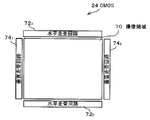
図2は、CMOS24の全体構成を示す平面図である。CMOS24の撮像領域70には、多数の画素(受光素子:フォトダイオード;図示せず)が二次元アレイ状に配列形成されている。この実施形態では、奇数行の画素行に対して偶数行の画素行が1/2画素ピッチづつずらして配列された、所謂、ハニカム画素配列とされている。
また、図2では図示を省略するが、本例示的実施形態では、位相差検出領域を含む撮像領域70の複数の画素の各々には、R(赤),G(緑),B(青)のカラーフィルタがベイヤ配列で配列された状態で積層されている。なお、RGBの配列は、ストライプ配列であってもよい。
本例示的実施形態に係るCMOS24には、更に、水平走査回路721、742と、垂直走査回路741、742が設けられている。なお、図示は省略するが、水平走査回路721、742には、水平信号線が接続され、垂直走査回路741、742には垂直選択線が接続されている。
垂直走査回路741は、垂直選択線を通じて、撮像領域70に配置された奇数行の第1の画素群の各画素を行(ライン)単位で選択する。この場合、最下端から一行ずつ順番に選択され、行毎に一括して画素信号の読み出しが行われる。なお、第1の画素群から行単位で読み出される各画素信号に対して相関二重サンプリングの処理を行ってリセット雑音を低減するCDS回路を設けてもよい。水平走査回路721は、第1の画素群から読み出された一行分の画素信号を、左端から順次画素単位で選択する。これにより、第1の画素群から読み出された各画素信号が水平信号線に出力される。このように水平信号線に順次出力される画素信号は後段のアンプ(図示せず)にて増幅された後に外部に出力される。
更にまた、垂直走査回路742は、垂直選択線を通じて、撮像領域70に配置された偶数行の第2の画素群の各画素を行単位で選択する。この場合、最下端から一行ずつ順番に選択され、行毎に一括して画素信号の読み出しが行われる。なお、第2の画素群から行単位で読み出される各画素信号に対して相関二重サンプリングの処理を行ってリセット雑音を低減するCDS回路を設けてもよい。水平走査回路722は、第2の画素群から出力される一行分の画素信号を、左端から順次画素単位で選択する。これにより、第2の画素群から読み出された各画素信号が水平信号線に出力される。このように水平信号線に順次出力される画素信号は後段のアンプ(図示せず)にて増幅された後に外部に出力される。
更にまた、垂直走査回路742は、垂直選択線を通じて、撮像領域70に配置された偶数行の第2の画素群の各画素を行単位で選択する。この場合、最下端から一行ずつ順番に選択され、行毎に一括して画素信号の読み出しが行われる。なお、第2の画素群から行単位で読み出される各画素信号に対して相関二重サンプリングの処理を行ってリセット雑音を低減するCDS回路を設けてもよい。水平走査回路722は、第2の画素群から出力される一行分の画素信号を、左端から順次画素単位で選択する。これにより、第2の画素群から読み出された各画素信号が水平信号線に出力される。このように水平信号線に順次出力される画素信号は後段のアンプ(図示せず)にて増幅された後に外部に出力される。
なお、本例示的実施形態では、撮像領域70の一部の領域、例えば中央位置に、矩形の位相差検出領域が設けられている。なお、位相差検出領域は、撮像領域70に対して1箇所だけ設けてもよいし、撮像領域70内のどこでもAF可能とできるよう複数箇所に設けてもよい。
図3は、位相差検出領域内の一部の表面拡大模式図である。図3には、位相差検出画素1xを配列したライン(ここでは奇数行)と、位相差検出画素1yを配列したライン(ここでは偶数行)とが交互に配列された状態が図示されている。位相差検出領域内においても、奇数行の画素行に対して偶数行の画素行が1/2画素ピッチづつずらして配列された、所謂ハニカム配列とされている。
なお、図3には、位相差検出画素1x、1yのみが配置されている様子が図示されているが、一部に撮像画素(位相差検出画素1x、1y以外の画素であって、遮光膜が設けられておらず、被写体画像を撮像するための通常の画素)が配置されていてもよい。また、位相差検出領域以外の撮像領域70には、撮像画素のみが配置されている(図示せず)。
図示する例では、各画素をR(赤),G(緑),B(青)で示している。R,G,Bは各画素上に積層したカラーフィルタの色を表し、奇数行の画素に対してカラーフィルタがベイヤ配列されると共に偶数行の画素に対してカラーフィルタがベイヤ配列されている。これにより、斜めに隣接する2つの位相差検出画素1x、1yを1つの組(ペア)としたときに、ペアを構成する斜めに隣接する2つの位相差検出画素1x、1yには、同色のカラーフィルタが配置された状態となっている。
また、位相差検出画素1x,1yは、その遮光膜開口2x,2yが撮像画素より小さく形成され、かつ、画素1xの遮光膜開口2xは左方向に偏心して設けられ、画素1yの遮光膜開口2yは、右方向(位相差検出方向)に偏心して設けられている。
このような構成により、位相差検出画素1xは、撮影レンズの主軸に対して一方の側(ここでは左側)を通過した光束が入射される。また、位相差検出画素1yは、ペアを構成する位相差検出画素1xに隣接するライン上に配置され、撮影レンズの主軸に対して他方の側(ここでは右側)を通過した光束が入射される。後述するように、ピントがずれた状態では、位相差検出画素1x、1yの各々が検出する像の位置、位相にズレが生じるため、このズレ量(位相差量)を検出して合焦制御が行なわれる。
なお、被写体測距のために全ての色の位相差検出画素ペアを用いる必要はなく、特定の色の位相差検出画素ペアのみを用いて位相差検出を行なってもよいし、特定の色の位相差検出画素ペアの中の特定の位相差検出画素ペアを用いて位相差検出を行なってもよい。また、位相差検出画素1x、1yを被写体画像の形成に用いることもできる。
図4は、G色のカラーフィルタが設けられた隣接する位相差検出画素1x,1yをペアとして被写体測距のための位相差検出に用いる場合の位相差検出方法を説明する説明図である。図4の下段に示す曲線Xは、横一行に並ぶG色の位相差検出画素1xの検出信号量をプロットしたグラフである。また、曲線Yは、これら画素1xと対になっているG色の位相差検出画素1yの検出信号量をプロットしたグラフである。
一対の位相差検出画素1x,1yは隣接画素であり極めて近接しているため、同一被写体からの光を受光していると考えられる。このため、後述するローリングシャッタによる歪みの影響が無ければ、曲線Xと曲線Yとはほぼ同一形状になると考えられ、その左右方向(位相差検出方向)のずれが、瞳分割した一対の位相差検出画素の一方の画素1xで見た画像と、他方の画素1yで見た画像との位相差量となる。
この曲線Xと曲線Yの相関演算を行うことで、横ズレ量(位相差量)を求めることができ、この位相差量により被写体までの距離を算出することが可能となる。曲線Xと曲線Yの相関量の評価値を求める方法は、公知の方法(例えば特開2010-8443号公報に記載された方法や特開2010-91991号公報に記載された方法)を採用すれば良い。例えば、曲線Xを構成する各点X(i)と、曲線Yを構成する各点Y(i+j)の差分の絶対値の積算値を評価値とし、最大評価値を与えるj値を、位相差量とする。
そして、この位相差量から求められた被写体までの距離に基づき、モータ駆動部34を制御して光学ユニット22の焦点調整モータを駆動してフォーカスレンズ位置を制御し、被写体に合焦させる。
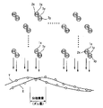
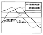
しかしながら、本例示的実施形態では固体撮像素子としてローリングシャッタ方式で制御されるCMOSを用いている。従って、読出しタイミングが同一でない2つの位相差検出画素からなる位相差検出画素ペアから取得される検出信号により相関演算を行なうと、このタイミングのずれの間に、被写体像が移動したり変化した場合、撮像された被写体像に歪みが生じ、相関演算で求めた位相差量に該ローリングシャッタによる歪みの影響(歪み量)が生じてしまう(図5Aも参照。)。
一方、図5Bに示すように、例えばラインの一端からの距離(水平方向の位置)が互いに等しい2つの位相差検出画素1x(図5Bでは位相差検出画素A,A’で示した)を1つの組(ペア)として、該ペアの検出信号の相関演算を行なえば、各位相差検出画素A、A’は、遮光膜開口の偏心方向が互いに等しい(撮影レンズの主軸に対して同じ側を通過した光束が入射される)こと。このから、本例示的実施形態は、ローリングシャッタによる歪み量のみを算出することができる。本例示的実施形態では、これら位相差検出画素のペアからの検出信号を用いて、上記通常の位相差検出画素ペアで算出された位相差量を補正して、AF制御を行なう。
なお、以下では、斜めに隣接し被写体測距のための位相差を検出する位相差検出画素のペア(位相差検出画素1x、1yからなるペア)を単に位相差検出画素ペアと呼称する。また、ローリングシャッタによる歪み量を検出するための位相差検出画素のペア(奇数行上に配置された2つの位相差検出画素1xからなるペア、又は偶数行上に配置された2つの位相差検出画素1yからなるペア)を、上記位相差検出画素ペアと区別するため、ローリング検出画素ペアと呼称する。
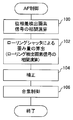
図6は、本例示的実施形態に係るAF制御の流れを示すフローチャートである。
ステップ100では、予め定められた斜めに隣接する位相差検出画素1x、1yからなる位相差検出画素ペアを構成する各位相差検出画素の各々から読み出された検出信号(以下、位相差検出画素信号と呼称する場合もある)の相関演算を行って、位相差量を求める。例えば、図7に示す例では、位相差検出画素ペアを構成する画素に斜線を付与した(後述する図8~図12も同様)。具体的には、7行目及び8行目の斜めに隣接するG色フィルタが設けられた一対の位相差検出画素1x、1yの各々を位相差検出画素ペアとして用いている。
ステップ102では、ローリング検出画素ペアを構成する各位相差検出画素の各々から読み出された検出信号(以下、ローリング検出画素信号と呼称する場合もある)の相関演算を行なって、ローリングシャッタによる歪み量を求める。例えば、上記位相差検出画素ペアのうち奇数行のライン上に配置された位相差検出画素1xと、該位相差検出画素1xが配置された奇数行のラインとは別の奇数行のライン上に配置され、同色のカラーフィルタが設けられた位相差検出画素1xとの組み合わせを、ローリング検出画素ペアとしてもよい。また、上記位相差検出画素ペアのうち偶数行のライン上に配置された位相差検出画素1yと、該位相差検出画素1yが配置された奇数行のラインとは別の奇数行のライン上に配置され、同色のカラーフィルタが設けられた位相差検出画素1yとの組み合わせを、ローリング検出画素ペアとしてもよい。図7では、ローリング検出画素ペアを構成する画素の一例を太線で示した(後述する図8~図12も同様)。具体的には、7行目のG色の位相差検出画素1xの各々と、11行目のG色の位相差検出画素1xとの組み合わせであって、各ラインの一端からの距離、すなわち水平方向の位置が等しい画素同士がローリング検出画素ペアとされている。
すなわち、図7に示す例では、7行目3列目の位相差検出画素1xと、11行目3列目の位相差検出画素1xとで構成されたローリング検出画素ペア、7行目7列目の位相差検出画素1xと、11行目7列目の位相差検出画素1xとで構成されたローリング検出画素ペア、7行目11列目の位相差検出画素1xと、11行目11列目の位相差検出画素1xとで構成されたローリング検出画素ペア、7行目15列目の位相差検出画素1xと、11行目15列目の位相差検出画素1xとで構成されたローリング検出画素ペアと、の各々の検出信号の相関演算を行ない、この相関演算により求められたズレ量に1/4を乗算し、ローリングシャッタによる歪み量を求める。
ここで1/4を乗算するのは、位相差検出画素ペアが、7行目及び8行目の画素であるのに対して、ローリング検出画素ペアは7行目及び11行目の画素である。このため、ローリング検出画素ペアの各画素の垂直方向の離間距離は、位相差検出画素ペアの各画素の垂直方向の離間距離の4倍になっており、読出に4倍の時間がかかる。
なお、ここでは、7行目と11行目のG画素の組(G色の位相差検出画素1xの組)でローリングシャッタによる歪み量を算出する例について説明した。しかしながら、7行目と15行目のG画素でローリングシャッタによる歪み量を算出するようにしてもよい。この場合には、ローリング検出画素信号の相関演算結果に1/8を乗算する必要がある。また、8行目と12行目のG画素の組(G色の位相差検出画素1yの組)でローリングシャッタによる歪み量を算出するようにしてもよい。
ステップ104では、ステップ100で求めた位相差量からステップ102で求めたローリングシャッタによる歪み量を減算して、ステップ100で求めた位相差量を補正する。
ステップ106では、補正された位相差量に基づいて、前述のように合焦制御を行なう。
(ローリングシャッタによる歪み量算出の変形例1)
なお、ローリングシャッタによる歪み量の算出方法は、上記図7を用いて説明した例に限定されない。例えば、複数のローリングシャッタによる歪み量を算出し、これを平均化して最終的なローリングシャッタによる歪み量を求めて、補正に用いるようにしてもよい。
具体的には、例えば、図7に示したローリング検出画素ペアから読み出した検出信号の相関演算を行なってローリングシャッタによる歪み量を求める(これを第1のローリングシャッタによる歪み量と呼称する)と共に、に加えて、図8に示すように、8行目4列目の位相差検出画素1yと、12行目4列目の位相差検出画素1yとで構成されたローリング検出画素ペア、8行目8列目の位相差検出画素1yと、12行目8列目の位相差検出画素1yとで構成されたローリング検出画素ペア、8行目12列目の位相差検出画素1yと、12行目12列目の位相差検出画素1yとで構成されたローリング検出画素ペア、8行目16列目の位相差検出画素1yと、12行目16列目の位相差検出画素1yとで構成されたローリング検出画素ペア、の各々から読み出した検出信号の相関演算を行なってもよい。さらに、この方法は、ローリングシャッタによる歪み量(これを第2のローリングシャッタによる歪み量と呼称する)を求めるように、第1のローリングシャッタによる歪み量と第2のローリングシャッタによる歪み量との平均値を求め、この平均値をステップ104における補正に用いてもよい。これにより、ローリングシャッタによる歪み量の算出精度が高くなり、AF制御の精度が向上する。
なお、ここでは、2つのローリングシャッタによる歪み量を算出して平均化して補正に用いる例について説明した。しかしながら、3つ以上のローリングシャッタによる歪み量を算出して平均化して補正に用いてもよい。
(ローリングシャッタによる歪み量算出の変形例2)
なお、デジタルカメラ10に、「通常撮影」モードと、「画素加算撮影」モードとが設けられていてもよい。「通常撮影」モードは、全画素の出力信号の個々から被写体の高精細画像を生成する。「画素加算撮影」モードは、全画素の出力信号を2画素加算或いは4画素加算など複数画素の信号を加算することで解像度を低解像度とする代わりに高感度撮影を行なう。どちらの撮影を行なうかは、タイミングジェネレータ32が固体撮像素子(CMOS)24に供給する駆動パルスの切り替えで行なう。4画素加算した結果、被写体画像の解像度は固体撮像素子の画素数に対して1/4となるが、露光量は4倍となる。このため、暗いシーンでも高S/Nの画像を得ることが可能となる。
この場合、AF制御も該撮影モードに応じた制御を行なうようにすればよい。すなわち、ラインの一端からの距離が互いに等しい複数の位相差検出画素1xの検出信号を加算した加算信号と、ラインの一端からの距離が互いに等しい複数の位相差検出画素1yの検出信号を加算した加算信号との相関演算を行なって位相差量を求めることができる。なお、以下では、ラインの一端からの距離が等しい複数画素からの検出信号を加算することを垂直加算という場合もある。
例えば、図9に示すように、3、7、11、15行目のG色の位相差検出画素1xの検出信号を加算した加算信号と、4、8、12、16行目のG色の位相差検出画素1yの検出信号を加算した加算信号との相関演算を行なって位相差量を求め、AF制御を行なう。そして、この場合においても、ローリングシャッタによる歪み量を算出して補正することができる。ここでは、7行目及び11行目のG色の位相検出画素1xだけでなく、3行目及び15行目のG色の位相差検出画素1xも組み合わせて用いる。
より具体的には、3行目のG色の位相差検出画素1xの検出信号と、11行目のG色の位相差検出画素1xの検出信号とを加算した加算信号aを、水平方向の位置が等しい画素毎に求め、7行目のG色の位相差検出画素1xの検出信号と、15行目のG色の位相差検出画素1xの検出信号とを加算した加算信号bを水平方向の位置が等しい画素毎に求め、水平方向の位置が等しい画素についての加算信号a、b同士の相関演算を行ない、ローリングシャッタによる歪み量を求めるようにしてもよい。
このように、多くの位相差検出画素を組み合わせてローリングシャッタによる歪み量の算出に用いることより、信号の高S/Nが上がり、ローリングシャッタによる歪み量算出の精度が向上する。
更にまた、4行目のG色の位相差検出画素1yの検出信号と、12行目のG色の位相差検出画素1yの検出信号とを加算した加算信号cを、水平方向の位置が等しい画素毎に求める。次に、8行目のG色の位相差検出画素1yの検出信号と、16行目のG色の位相差検出画素1yの検出信号とを加算した加算信号dを、水平方向の位置が等しい画素毎に求める。次に、水平方向の位置が等しい画素についての加算信号c、d同士の相関演算を行ない、ローリングシャッタによる歪み量を求め、更に、上記加算信号abから求めたローリングシャッタによる歪み量との平均値を最終的なローリングシャッタによる歪み量として求めてもよい。
(ローリングシャッタによる歪み量算出の変形例3)
更にまた、異なる色の画素を用いて垂直加算して、ローリングシャッタによる歪み量を求めることができる(図示せず)。具体的には、例えば、5行目のR色の位相差検出画素1xの検出信号と7行目のG色の位相差検出画素1xの検出信号とを加算した加算信号eを、水平方向の位置が等しい画素毎に求める。次に、7行目のG色の位相差検出画素1xの検出信号と9行目のR色の位相差検出画素1xの検出信号とを加算した加算信号fを水平方向の位置が等しい画素毎に求め、水平方向の位置が等しい画素についての加算信号e、fの相関演算を行なって、ローリングシャッタによる歪み量を求めるようにしてもよい。
(ローリングシャッタによる歪み量算出の変形例4)
更にまた、図示は省略するが、図8で例示したように2以上のローリングシャッタによる歪み量を求めて平均化して用いる場合にも、異なる色の画素を用いて垂直加算して、ローリングシャッタによる歪み量を求めることができる。
具体的には、例えば、5行目のR色の位相差検出画素1xの検出信号と7行目のG色の位相差検出画素1xの検出信号とを加算した加算信号eを、水平方向の位置が等しい画素毎に求める。次に、7行目のG色の位相差検出画素1xの検出信号と9行目のR色の位相差検出画素1xの検出信号とを加算した加算信号fを水平方向の位置が等しい画素毎に求める。次に、水平方向の位置が等しい画素についての加算信号e、fの相関演算を行なって、ローリングシャッタによる歪み量を求め(これを第1のローリングシャッタによる歪み量と呼称)、且つ6行目のR色の位相差検出画素1yの検出信号と8行目のG色の位相差検出画素1yの検出信号とを加算した加算信号gを、水平方向の位置が等しい画素毎に求める。次に、8行目のG色の位相差検出画素1yの検出信号と10行目のR色の位相差検出画素1yの検出信号とを加算した加算信号hを水平方向の位置が等しい画素毎に求める。次に、水平方向の位置が等しい画素についての加算信号g、hの相関演算を行なって、ローリングシャッタによる歪み量を求め(これを第2のローリングシャッタによる歪み量と呼称)る。さらに、第1のローリングシャッタによる歪み量と第2のローリングシャッタによる歪み量との平均値を、最終的なローリングシャッタによる歪み量として求め、位相差量の補正に用いる。
これにより、ローリングシャッタによる歪み量の算出精度を高め、AF制御の精度を向上できる。
(ローリングシャッタによる歪み量算出の変形例5)
また、垂直方向に等しい位置に並んだ異なる色の複数のローリング検出画素ペアの検出信号から求めた複数のローリングシャッタによる歪み量を平均化して用いることもできる。以下、図10、図11、図12を参照して説明する。なお、図10、図11、図12においても、図7、図8、図9と同様に、斜線が付与されている画素が、測距に用いる位相差量の算出に用いる画素であって、太線で描画されている画素が、ローリングシャッタによる歪み量の算出に用いる画素である。
図10に示すように、7行目のG色の位相差検出画素1xと、8行目の位相差検出画素1yとを位相差検出画素ペアとして位相差量を求める場合に、7行目と11行目のG色の検出信号の相関演算により求めたローリングシャッタによる歪み量と、7行目と11行目のB画素の相関演算により求めたローリングシャッタによる歪み量とを平均して最終的なローリングシャッタによる歪み量を求め、これを位相差量の補正に用いてもよい。
また、図11に示すように、7行目のG色の位相差検出画素1xと、8行目の位相差検出画素1yとを位相差検出画素ペアとして位相差量を求める場合に、まず、7行目と11行目のG色の検出信号の相関演算により求めたローリングシャッタによる歪み量と、7行目と11行目のB画素の検出信号の相関演算により求めたローリングシャッタによる歪み量とを平均して第1のローリングシャッタによる歪み量を求める。更に、8行目と12行目のG色の検出信号の相関演算により求めたローリングシャッタによる歪み量と、8行目と12行目のB画素の検出信号の相関演算により求めたローリングシャッタによる歪み量とを平均して第2のローリングシャッタによる歪み量を求める。そして、第1のローリングシャッタによる歪み量と第2のローリングシャッタによる歪み量との平均値を、最終的なローリングシャッタによる歪み量として求め、これを位相差量の補正に用いてもよい。
また、図12に示すように、垂直加算してローリングシャッタによる歪み量を求める場合も同様に、まず、3行目のG色の位相差検出画素1xの検出信号と、11行目のG色の位相差検出画素1xの検出信号とを加算した加算信号kを水平方向の位置が等しい画素毎に求める。次に、7行目のG色の位相差検出画素1xの検出信号と、15行目のG色の位相差検出画素1xの検出信号とを加算した加算信号lを水平方向の位置が等しい画素毎に求める。次に、水平方向の位置が等しい画素についての加算信号k、lの相関演算を行ない、第1のローリングシャッタによる歪み量を求める。更に、3行目のB色の位相差検出画素1xの検出信号と、11行目のB色の位相差検出画素1xの検出信号とを加算した加算信号mを水平方向の位置が等しい画素毎に求め、7行目のB色の位相差検出画素1xの検出信号と、15行目のB色の位相差検出画素1xの検出信号とを加算した加算信号nを水平方向の位置が等しい画素毎に求める。さらに、水平方向の位置が等しい画素についての加算信号m、nの相関演算を行ない、第2のローリングシャッタによる歪み量を求める。そして、第1のローリングシャッタによる歪み量と第2のローリングシャッタによる歪み量との平均値を、最終的なローリングシャッタによる歪み量として求め、これを位相差量の補正に用いてもよい。
なお、以下のようにローリングシャッタによる歪み量を求めてもよい(図示せず)。まず、図12を用いて説明したように演算して求めた最終的なローリングシャッタによる歪み量をここでは最終的なローリングシャッタによる歪み量とせずに、仮にこれをローリングシャッタによる歪み量Aとする。更に、4行目のG色の位相差検出画素1yの検出信号と、12行目のG色の位相差検出画素1yの検出信号とを加算した加算信号pを水平方向の位置が等しい画素毎に求める。次に、8行目のG色の位相差検出画素1yの検出信号と、16行目のG色の位相差検出画素1yの検出信号とを加算した加算信号qを水平方向の位置が等しい画素毎に求め、水平方向の位置が等しい画素についての加算信号p、qの相関演算を行なって、第3のローリングシャッタによる歪み量を求める。次に、4行目のB色の位相差検出画素1yの検出信号と、12行目のB色の位相差検出画素1yの検出信号とを加算した加算信号rを水平方向の位置が等しい画素毎に求め、8行目のB色の位相差検出画素1yの検出信号と、16行目のB色の位相差検出画素1yの検出信号とを加算した加算信号sを水平方向の位置が等しい画素毎に求める。さらに、水平方向の位置が等しい画素についての加算信号r、sの相関演算を行なって、第4のローリングシャッタによる歪み量を求める。さらに、第3のローリングシャッタによる歪み量と第4のローリングシャッタによる歪み量との平均値を、ローリングシャッタによる歪み量Bとする。そして、上記ローリングシャッタによる歪み量Aとローリングシャッタによる歪み量Bとの平均値を最終的なローリングシャッタによる歪み量として求め、これを位相差量の補正に用いるようにしてもよい。
このように、異なる色のローリング検出画素ペアを用いて平均化してローリングシャッタによる歪み量を算出して、ローリングシャッタによる歪み量の算出精度を高めることができる。
なお、本例示的実施形態では、常にローリング補正を行なう例について説明したが、これに限定されず、例えば、AF制御においてローリング補正を行なう第1のモードと、ローリング補正を行なわない第2のモードとを切り替える切替手段を設け、利用者が該切替手段により切り替えたモードに応じて、AF制御を行なうようにしてもよい。
[第2の例示的実施形態]
なお、ローリングシャッタによる歪み量は、被写体の動きや画角の変化によって変動するため、一定とは限らない。そこで、上記図8や図10~図12を用いて説明したように、複数のローリングシャッタによる歪み量を平均化して最終的なローリングシャッタによる歪み量を算出する場合において、該複数のローリングシャッタによる歪み量が大きく異なる場合には、急激に被写体の動きもしくは画角が変化したと判断して、AF動作を中止してもよい。以下、この制御ついて詳細に説明する。なお、本例示的実施形態のデジタルカメラ10の構成は第1の例示的実施形態と同様であるため、説明を省略する
図13において、ステップ110では、第1の例示的実施形態で説明したように位相差検出画素信号の相関演算を行なって、位相差量を求める。
ステップ112では、第1の例示的実施形態で図8、図10~12を用いて説明したように、複数のローリングシャッタによる歪み量を求め、これらを平均化して最終的なローリングシャッタによる歪み量を求める。なお、最終的なローリングシャッタによる歪み量を算出する前に算出した複数のローリングシャッタによる歪み量については、下記ステップ114での判断が終了するまで予め定められた記憶手段に記憶しておく。
ステップ114では、記憶手段に記憶されている(最終的なローリングシャッタによる歪み量除く)複数のローリングシャッタによる歪み量を互いに比較し、その差分が閾値以上となったものがあるか否かを判断する。ここで否定判断した場合には、ステップ116に進み、上記最終的に求めたローリングシャッタによる歪み量をステップ110で求めた位相差量から減算して補正する。そして、ステップ118で該補正した位相差量に基づいて合焦点制御する。
一方、ステップ114で肯定判断した場合には、ステップ120に進み、エラー処理を行なって、本AF制御を終了する。エラー処理とは、例えば、エラーメッセージを表示する等である。また、いったん本AF制御を終了した後、AF制御を再実行するようにしてもよい。
以上説明したように、ローリングシャッタによる歪み量の差が大きければ、合焦制御する前にAF制御ルーチンを終了するようにしたため、誤合焦を防止することができる。
なお、ここでは、ステップ114で判断する前に最終的なローリングシャッタによる歪み量を求める例について説明したが、ステップ114で否定判断された後に、最終的なローリングシャッタによる歪み量を求め、補正に用いてもよい。
また、デジタルカメラ10に、AF制御においてローリング補正を行なう第1のモードと、本例示的実施形態で説明したように算出された複数のローリングシャッタによる歪み量の差が大きい場合には、ローリング補正を行なわないようにする第2のモードとを切り替える切替手段を設け、利用者が該切替手段により切り替えたモードに応じて、AF制御を行なうようにしてもよい。
[第3の例示的実施形態]
第1の例示的実施形態では、AF制御の際は常にローリングシャッタによる歪み量を算出して補正する例について説明したが、ローリングシャッタによる歪みの影響が小さいと推定される場合にはローリングシャッタによる歪み量を算出して補正する処理を省略してもよい。以下、詳細に説明する。
なお、本例示的実施形態のデジタルカメラ10の構成は第1の例示的実施形態と同様であるため、説明を省略する。
図14は、本例示的実施形態に係るAF制御処理の流れの一例を示すフローチャートである。
ステップ200では、第1の例示的実施形態で説明したように位相差検出画素信号の相関演算を行なって、位相差量を求める。
ステップ202では、AF領域が予め定められた閾値以上の大きさか否かを判断する。ここで、AF領域とは、焦点を合わせる領域であり、デジタルカメラ10が、その使用者により任意にその位置や大きさを設定できるよう構成されている場合や、撮影モードに応じてAF領域の大きさが設定されるように構成されている場合等もある。本例示的実施形態では、デジタルカメラ10に設定されているAF領域の大きさの情報を取得し、予め定められた閾値と比較する。
ステップ202で肯定判断した場合には、ステップ204で、第1の例示的実施形態で説明したようにローリング検出画素信号の相関演算を行なって、ローリングシャッタによる歪み量を求める。ステップ206では、ステップ200で求めた位相差量からステップ204で求めたローリングシャッタによる歪み量を減算して、ステップ200で求めた位相差量を補正する。そして、ステップ208では、補正された位相差量に基づいて、合焦制御を行なう。
一方、ステップ202で否定判断した場合には、ステップ204、ステップ206をスキップして、ステップ208に進む。この場合には、ステップ208では、ステップ200で求めた位相差量(ローリングシャッタによる歪み量で補正していない位相差量)をそのまま用いて、合焦制御を行なう。
AF領域がそれほど大きくなければ、測距のための位相差を検出する位相差検出画素数も少なくなり、ローリングシャッタによる歪みの影響は小さいと考えられる。そこで、本例では、AF領域が閾値未満であれば、ローリングシャッタによる歪み量の算出及び補正は行なわずにAF制御を行なうようにした。これにより、AF制御にかかる時間を短縮することができる。
図15は、AF制御処理の流れの他の例を示すフローチャートである。
ステップ300では、第1の例示的実施形態で説明したように位相差検出画素信号の相関演算を行なって、位相差量を求める。
ステップ302では、読出し画素数(ステップ300で位相差量を演算するために用いられた位相差検出画素の数)が予め定められた閾値以上か否かを判断する。ステップ302で肯定判断した場合には、ステップ304で、第1の例示的実施形態で説明したようにローリング検出画素信号の相関演算を行なって、ローリングシャッタによる歪み量を求める。ステップ306では、ステップ300で求めた位相差量からステップ304で求めたローリングシャッタによる歪み量を減算して、ステップ300で求めた位相差量を補正する。そして、ステップ308では、補正された位相差量に基づいて、合焦制御を行なう。
一方、ステップ302で否定判断した場合には、ステップ304、ステップ306をスキップして、ステップ308に進む。この場合には、ステップ308では、ステップ300で求めた位相差量(ローリングシャッタによる歪み量で補正していない位相差量)をそのまま用いて、合焦制御を行なう。
読出し画素数が少なければ、ローリングシャッタによる歪みの影響は小さいと考えられる。そこで、本例示的実施形態では、読出し画素数が閾値未満であれば、ローリングシャッタによる歪み量の算出及び補正は行なわずにAF制御を行なうようにした。これにより、AF制御にかかる時間を短縮することができる。
なお、上記閾値を、画角に応じて変更するようにしてもよい。より具体的には、例えば、デジタルカメラ10が、ワイド(広角)モード・標準モード・テレ(望遠)モードに切り替え可能な構成であれば、各モード毎に閾値を予め設定しておき、AF制御時の撮影モードに応じて、上記閾値を変更するようにしてもよい。なお、画角がテレ側であるほど、ローリングシャッタによる歪みの影響が大きくなると推定されるため、ワイド側に比べてテレ側の閾値を小さく設定しておくようにしてもよい。
図16は、AF制御処理の流れの他の例を示すフローチャートである。
ステップ400では、第1の例示的実施形態で説明したように位相差検出画素信号の相関演算を行なって、位相差量を求める。
ステップ402では、被写体距離が閾値以上か否かを判断する。ここでは、上記ステップ400で求めた位相差量から暫定的に求めた被写体距離を予め定められた閾値と比較する。ここで比較される閾値は、AF領域の大きさ或いは上記読出し画素数に応じて変更されるものとする。ステップ402で肯定判断した場合には、ステップ404で、第1の例示的実施形態で説明したようにローリング検出画素信号の相関演算を行なって、ローリングシャッタによる歪み量を求める。ステップ406では、ステップ400で求めた位相差量からステップ406で求めたローリングシャッタによる歪み量を減算して、ステップ400で求めた位相差量を補正する。そして、ステップ408では、補正された位相差量に基づいて、合焦制御を行なう。
一方、ステップ402で否定判断した場合には、ステップ404、ステップ406をスキップして、ステップ408に進む。この場合には、ステップ408では、ステップ400で求めた位相差量(ローリングシャッタによる歪み量で補正していない位相差量)をそのまま用いて、合焦制御を行なう。
ローリングは撮影画角内の被写体の動きで影響度が変わる。特に被写体距離が長いほど、ローリングシャッタによる歪みの影響は大きくなると考えられる。そこで、本例では、被写体距離が閾値以上長い場合に、ローリングシャッタによる歪み量の算出及び補正を行ない、被写体距離が閾値より短い場合には、ローリングシャッタによる歪み量の算出及び補正を行なわないようにした。
図17は、AF制御処理の流れの他の例を示すフローチャートである。
ステップ500では、第1の例示的実施形態で説明したように位相差検出画素信号の相関演算を行なって、位相差量を求める。
ステップ502では、画角内の動体検出を行なう。例えば、メモリ48に記憶された過去の画像データと今回の画像データとの間で周知の動きベクトルを算出し、該動きベクトルの大きさに基づいて検出してもよい。
ステップ504では、上記検出結果に基づき、画角内に動体が存在するか否かを判断する。ステップ402で肯定判断した場合には、ステップ506で、第1の例示的実施形態で説明したようにローリング検出画素信号の相関演算を行なって、ローリングシャッタによる歪み量を求める。ステップ508では、ステップ500で求めた位相差量からステップ506で求めたローリングシャッタによる歪み量を減算して、ステップ500で求めた位相差量を補正する。そして、ステップ510では、補正された位相差量に基づいて、合焦制御を行なう。
一方、ステップ504で否定判断した場合には、ステップ506、ステップ508をスキップして、ステップ510に進む。この場合には、ステップ510では、ステップ500で求めた位相差量(ローリングシャッタによる歪み量で補正していない位相差量)をそのまま用いて、合焦制御を行なう。
ローリングは撮影画角内に動体が存在する場合に起こる。従って、本例では、動体を検出して、動体が存在する場合にのみローリングシャッタによる歪み量の算出及び補正を行ない、動体が存在しない場合には、ローリングシャッタによる歪み量の算出及び補正を行なわないようにした。
図18は、AF制御処理の流れの他の例を示すフローチャートである。
ステップ600では、第1の例示的実施形態で説明したように位相差検出画素信号の相関演算を行なって、位相差量を求める。
ステップ602では、AF領域内の動体検出を行なう。動体検出は、例えば、メモリ48に記憶された過去の画像データと今回の画像データとの間で周知の動きベクトルを算出し、該動きベクトルの大きさに基づいて検出してもよい。
ステップ604では、上記検出結果に基づき、AF領域内に動体が存在するか否かを判断する。ステップ602で肯定判断した場合には、ステップ606で、第1の例示的実施形態で説明したようにローリング検出画素信号の相関演算を行なって、ローリングシャッタによる歪み量を求める。ステップ608では、ステップ600で求めた位相差量からステップ606で求めたローリングシャッタによる歪み量を減算して、ステップ600で求めた位相差量を補正する。そして、ステップ610では、補正された位相差量に基づいて、合焦制御を行なう。
一方、ステップ604で否定判断した場合には、ステップ606、ステップ608をスキップして、ステップ610に進む。この場合には、ステップ610では、ステップ600で求めた位相差量(ローリングシャッタによる歪み量で補正していない位相差量)をそのまま用いて、合焦制御を行なう。
ローリングは撮影画角内に動体が存在する場合に起こる。従って、本例では、特にAF領域内で動体を検出して、AF領域内に動体が存在する場合にのみローリングシャッタによる歪み量の算出及び補正を行ない、動体が存在しない場合には、ローリングシャッタによる歪み量の算出及び補正を行なわないようにした。
以上説明したように、本例示的実施形態では、ローリングシャッタによる歪みの影響が少ないと推定される場合には、ローリングシャッタによる歪み量の算出及び補正を行なわないようにし、それ以外の場合には、ローリングシャッタによる歪み量を算出して補正を行なうようにした。このため、本例示的実施形態では、ローリングシャッタによる歪みの影響を抑制しつつ、AF制御において無駄な時間を削減できる。
なお、本例示的実施形態では、AF領域の大きさ、読出し画素数、被写体距離、撮影画角内の被写体の動き、AF領域内の被写体の動きのいずれかに応じて、ローリングシャッタによる歪み量の算出及び補正を行なうか否かを判断した。しかしながら、本発明は、これに限定されない。例えば、AF領域の大きさ、読出し画素数、被写体距離、撮影画角内の被写体の動き、AF領域内の被写体の動きの少なくとも1つに応じて、ローリングシャッタによる歪み量の算出及び補正を行なうか否かを判断するようにしてもよい。
また、デジタルカメラ10に、第1の例示的実施形態で説明したように常にローリング補正を行なう第1のモードと、第3の例示的実施形態で説明したようにローリングシャッタによる歪みの影響が小さいと推定される場合にはローリング補正を行なわないようにする第2のモードとを切り替える切替手段を設けてもよい。この場合、利用者が該切替手段により切り替えたモードに応じて、AF制御を行なうようにしてもよい。
また、上記各例示的実施形態では、撮像領域の一部に位相差検出領域を設けた例について説明した。しかしながら、本発明は、これに限定されるものではなくい。例えば、被写体の撮像に用いられる固体撮像素子とは別に位相差検出専用の撮像素子を設け、該撮像素子により位相差AF方式でAF制御する際にも、本発明を適用可能である。
また、位相差検出画素1x、1yは、上記各例示的実施形態で示した例に限定されない。例えば、位相差検出画素1xを、右半分が遮光され、左半分が開口された構成とし、位相差検出画素1yを、左半分が遮光され、右半分が開口された構成としてもよい。これによっても、上記と同様に、位相差検出画素1xには、撮影レンズの主軸に対して一方の側(左側)を通過した光束が入射され、位相差検出画素1yには、撮影レンズの主軸に対して他方の側(右側)を通過した光束が入射される。
また、上記各例示的実施形態では、位相差検出画素ペアを構成する位相差検出画素が隣接している画素である場合について説明した。しかしながら、例えば、互いに隣接しておらず、ペアを構成する画素の間に他の画素が配置されていてもよい。
なお、上記各例示的実施形態では、本発明をデジタルカメラに適用した場合について説明した。しかしながら、本発明はこれに限定されるものではない。例えば、携帯電話機、PDA等の撮影機能を有する他の装置に適用する形態とすることもできる。この場合も、上記各例示的実施形態と同様の効果を奏することができる。
更に、上記各例示的実施形態において説明した各種処理プログラムの処理の流れは一例であり、本発明の主旨を逸脱しない範囲内において、各ステップの処理順序の変更、処理内容の変更、不要なステップの削除、新たなステップの追加等を行なうことができることは言うまでもない。
日本出願2011-080033の開示は、その全体が参照により本明細書に取り込まれる。
本明細書に記載された全ての文献、特許出願、および技術規格は、個々の文献、特許出願、および技術規格が参照により取り込まれることが具体的かつ個々に記された場合と同程度に、本明細書中に参照により取り込まれる。
日本出願2011-080033の開示は、その全体が参照により本明細書に取り込まれる。
本明細書に記載された全ての文献、特許出願、および技術規格は、個々の文献、特許出願、および技術規格が参照により取り込まれることが具体的かつ個々に記された場合と同程度に、本明細書中に参照により取り込まれる。
Claims (8)
- 撮影レンズの主軸に対して一方の側を通過した光束が入射される第1の位相差検出画素を配列した第1のラインと、前記撮影レンズの主軸に対して他方の側を通過した光束が入射される第2の位相差検出画素を配列した第2のラインと、を交互に複数配列した撮像素子と、
前記撮像素子に対し、ローリングシャッタ方式で前記撮像素子に配列された位相差検出画素の信号を読み出す読出手段と、
前記第1の位相差検出画素及び前記第2の位相差検出画素からなる組から読み出された信号の相関演算を行なう第1の相関演算手段と、
前記第1のライン上に配置された複数の第1の位相差検出画素からなる組、及び前記第2のライン上に配置された複数の第2の位相差検出画素からなる組の少なくとも一方の組から読み出された信号の相関演算を行なう第2の相関演算手段と、
前記第1の相関演算手段による相関演算結果を、前記第2の相関演算手段による相関演算結果により補正する補正手段と、
前記補正された相関演算結果を用いて合焦制御する合焦手段と、
を備えた撮像装置。 - 前記第2の相関演算手段は、複数組の相関演算を行ない、
前記補正手段は、前記第1の相関演算手段による相関演算結果を、前記第2の相関演算手段による複数組の相関演算結果の平均値により補正する
請求項1に記載の撮像装置。 - 前記第2の相関演算手段は、4つ以上の位相差検出画素で構成された組から読み出された信号の相関演算を行なう場合には、該4つ以上の位相差検出画素を2つの群に分け、一方の群の検出信号を加算した加算信号と、他方の群の検出信号を加算した加算信号とを相関演算する
請求項1又は請求項2に記載の撮像装置。 - 前記第2の相関演算手段により複数組の各々の相関演算結果が得られた場合に、該複数組の各々の相関演算結果同士を比較する比較手段と、
前記比較手段により、予め定められた閾値以上異なる相関演算結果が存在する場合には、合焦制御が中止されるように制御するか、又は合焦制御を中止した後に再度読出手段による読み出しが行なわれて合焦制御が行なわれるように制御する制御手段と、
を更に備えた請求項1~請求項3のいずれか1項記載の撮像装置。 - 前記第2の相関演算手段は、前記第1の位相差検出画素及び前記第2の位相差検出画素からなる組の位相差検出画素に設けられたカラーフィルタの色と同じ色のカラーフィルタが設けられた位相差検出画素の組から読み出された信号の相関演算を行なう、
請求項1~請求項4のいずれか1項記載の撮像装置。 - 前記第2の相関演算手段は、前記第1の位相差検出画素及び前記第2の位相差検出画素からなる組の位相差検出画素に設けられたカラーフィルタの色と異なる色のカラーフィルタが設けられた位相差検出画素の組を含む組から読み出された信号の相関演算を行なう、
請求項1~請求項4のいずれか1項記載の撮像装置。 - 焦点を合わせる焦点領域の大きさ、前記第1の相関演算手段での相関演算に用いられる信号を読み出す位相差検出画素の数、撮影画角内の被写体の動き、及び前記焦点領域内の被写体の動き、の少なくとも1つに基づいて、前記補正手段による補正を行なうか否かを判断する判断手段を更に備え、
前記合焦手段は、前記判断手段により前記補正手段による補正を行なわないと判断された場合には、前記補正手段による補正の実行を中止し、前記補正される前の前記第1の相関演算手段の相関演算結果を用いて合焦制御する
請求項1~請求項6のいずれか1項記載の撮像装置。 - 撮影レンズの主軸に対して一方の側を通過した光束が入射される第1の位相差検出画素を配列した第1のラインと、前記撮影レンズの主軸に対して他方の側を通過した光束が入射される第2の位相差検出画素を配列した第2のラインと、を交互に複数配列した撮像素子を備えた撮像装置で行なわれる合焦制御方法であって、
前記撮像素子に対し、ローリングシャッタ方式で前記撮像素子に配列された位相差検出画素の信号を読み出す読出ステップと、
前記第1の位相差検出画素及び前記第2の位相差検出画素からなる組から読み出された信号の相関演算を行なう第1の相関演算ステップと、
前記第1のライン上に配置された複数の第1の位相差検出画素からなる組、及び前記第2のライン上に配置された複数の第2の位相差検出画素からなる組の少なくとも一方の組から読み出された信号の相関演算を行なう第2の相関演算ステップと、
前記第1の相関演算ステップによる相関演算結果を、前記第2の相関演算ステップによる相関演算結果により補正する補正手段と、
前記補正された相関演算結果を用いて合焦制御する合焦ステップと、
を備えた合焦制御方法。
Priority Applications (4)
| Application Number | Priority Date | Filing Date | Title |
|---|---|---|---|
| CN201280009830.XA CN103403599B (zh) | 2011-03-31 | 2012-03-08 | 摄像装置及其对焦控制方法 |
| JP2013507331A JP5468177B2 (ja) | 2011-03-31 | 2012-03-08 | 撮像装置及びその合焦制御方法 |
| US13/974,928 US20130335606A1 (en) | 2011-03-31 | 2013-08-23 | Imaging device and focus control method |
| US14/323,822 US8964098B2 (en) | 2011-03-31 | 2014-07-03 | Imaging device and focus control method having first and second correlation computations |
Applications Claiming Priority (2)
| Application Number | Priority Date | Filing Date | Title |
|---|---|---|---|
| JP2011080033 | 2011-03-31 | ||
| JP2011-080033 | 2011-03-31 |
Related Child Applications (1)
| Application Number | Title | Priority Date | Filing Date |
|---|---|---|---|
| US13/974,928 Continuation US20130335606A1 (en) | 2011-03-31 | 2013-08-23 | Imaging device and focus control method |
Publications (1)
| Publication Number | Publication Date |
|---|---|
| WO2012132827A1 true WO2012132827A1 (ja) | 2012-10-04 |
Family
ID=46930566
Family Applications (1)
| Application Number | Title | Priority Date | Filing Date |
|---|---|---|---|
| PCT/JP2012/056024 Ceased WO2012132827A1 (ja) | 2011-03-31 | 2012-03-08 | 撮像装置及びその合焦制御方法 |
Country Status (4)
| Country | Link |
|---|---|
| US (2) | US20130335606A1 (ja) |
| JP (1) | JP5468177B2 (ja) |
| CN (1) | CN103403599B (ja) |
| WO (1) | WO2012132827A1 (ja) |
Cited By (8)
| Publication number | Priority date | Publication date | Assignee | Title |
|---|---|---|---|---|
| CN104425635A (zh) * | 2013-09-03 | 2015-03-18 | (株)赛丽康 | 使用显微透镜的相位差检测像素 |
| JP2015079193A (ja) * | 2013-10-18 | 2015-04-23 | キヤノン株式会社 | 撮像装置、撮像システム、撮像装置の制御方法、プログラム、および、記憶媒体 |
| US9048152B2 (en) | 2011-09-27 | 2015-06-02 | Canon Kabushiki Kaisha | Image pickup apparatus and focus detection method |
| JP2015203793A (ja) * | 2014-04-15 | 2015-11-16 | キヤノン株式会社 | 撮像装置、制御装置、制御方法、プログラム、および、記憶媒体 |
| JP2015210489A (ja) * | 2014-04-30 | 2015-11-24 | キヤノン株式会社 | 撮像装置及び撮像方法 |
| JP2017212723A (ja) * | 2016-05-18 | 2017-11-30 | キヤノン株式会社 | 撮像装置および制御方法 |
| WO2018221382A1 (ja) * | 2017-05-31 | 2018-12-06 | キヤノン株式会社 | 撮像素子及び撮像装置 |
| JP2019070610A (ja) * | 2017-10-11 | 2019-05-09 | キヤノン株式会社 | 測距装置および測距方法 |
Families Citing this family (10)
| Publication number | Priority date | Publication date | Assignee | Title |
|---|---|---|---|---|
| JP6053652B2 (ja) * | 2013-09-20 | 2016-12-27 | 富士フイルム株式会社 | 撮像装置及び合焦制御方法 |
| US9554048B2 (en) * | 2013-09-26 | 2017-01-24 | Apple Inc. | In-stream rolling shutter compensation |
| JP6270400B2 (ja) * | 2013-10-09 | 2018-01-31 | オリンパス株式会社 | 画像処理装置、画像処理方法及び画像処理プログラム |
| JP5744161B2 (ja) * | 2013-11-18 | 2015-07-01 | シャープ株式会社 | 画像処理装置 |
| FR3017219B1 (fr) | 2014-01-31 | 2016-03-11 | Commissariat Energie Atomique | Amplificateur parametrique optique d'impulsions ultra-courtes |
| KR102269600B1 (ko) * | 2014-08-05 | 2021-06-25 | 삼성전자주식회사 | 위상차 포커스 검출 가능한 촬상소자 |
| JP6182681B2 (ja) * | 2014-11-18 | 2017-08-16 | 富士フイルム株式会社 | 合焦制御装置、合焦制御方法、合焦制御プログラム、レンズ装置、撮像装置 |
| JP6236580B2 (ja) * | 2015-09-30 | 2017-11-22 | 富士フイルム株式会社 | 合焦制御装置、合焦制御方法、合焦制御プログラム、レンズ装置、撮像装置 |
| KR102477757B1 (ko) * | 2015-12-16 | 2022-12-14 | 에스케이하이닉스 주식회사 | 자동 초점 시스템 및 방법 |
| CN112308783B (zh) * | 2019-07-24 | 2024-06-28 | 株式会社理光 | 一种卷帘效应校正方法、装置及计算机可读存储介质 |
Citations (3)
| Publication number | Priority date | Publication date | Assignee | Title |
|---|---|---|---|---|
| JP2008072470A (ja) * | 2006-09-14 | 2008-03-27 | Nikon Corp | 光電変換素子および撮像装置 |
| JP2008263352A (ja) * | 2007-04-11 | 2008-10-30 | Nikon Corp | 撮像素子、焦点検出装置および撮像装置 |
| JP2009128579A (ja) * | 2007-11-22 | 2009-06-11 | Nikon Corp | 焦点検出装置および撮像装置 |
Family Cites Families (7)
| Publication number | Priority date | Publication date | Assignee | Title |
|---|---|---|---|---|
| JP4946313B2 (ja) | 2006-09-27 | 2012-06-06 | 株式会社ニコン | 撮像装置 |
| JP4349407B2 (ja) | 2006-11-17 | 2009-10-21 | ソニー株式会社 | 撮像装置 |
| JP5095519B2 (ja) | 2008-06-24 | 2012-12-12 | 三星電子株式会社 | 撮像装置及び撮像方法 |
| JP5276371B2 (ja) * | 2008-07-09 | 2013-08-28 | キヤノン株式会社 | 撮像装置 |
| JP2010020015A (ja) | 2008-07-09 | 2010-01-28 | Canon Inc | 撮像装置 |
| JP5097077B2 (ja) | 2008-10-10 | 2012-12-12 | キヤノン株式会社 | 撮像装置及びその制御方法及びプログラム |
| CN103380392B (zh) * | 2011-03-31 | 2014-12-03 | 富士胶片株式会社 | 摄像装置及其对焦控制方法 |
-
2012
- 2012-03-08 JP JP2013507331A patent/JP5468177B2/ja active Active
- 2012-03-08 WO PCT/JP2012/056024 patent/WO2012132827A1/ja not_active Ceased
- 2012-03-08 CN CN201280009830.XA patent/CN103403599B/zh active Active
-
2013
- 2013-08-23 US US13/974,928 patent/US20130335606A1/en not_active Abandoned
-
2014
- 2014-07-03 US US14/323,822 patent/US8964098B2/en active Active
Patent Citations (3)
| Publication number | Priority date | Publication date | Assignee | Title |
|---|---|---|---|---|
| JP2008072470A (ja) * | 2006-09-14 | 2008-03-27 | Nikon Corp | 光電変換素子および撮像装置 |
| JP2008263352A (ja) * | 2007-04-11 | 2008-10-30 | Nikon Corp | 撮像素子、焦点検出装置および撮像装置 |
| JP2009128579A (ja) * | 2007-11-22 | 2009-06-11 | Nikon Corp | 焦点検出装置および撮像装置 |
Cited By (16)
| Publication number | Priority date | Publication date | Assignee | Title |
|---|---|---|---|---|
| DE102012217165B4 (de) | 2011-09-27 | 2019-09-19 | Canon Kabushiki Kaisha | Bildaufnahmevorrichtung und Brennpunkterfassungsverfahren |
| US9048152B2 (en) | 2011-09-27 | 2015-06-02 | Canon Kabushiki Kaisha | Image pickup apparatus and focus detection method |
| GB2497160B (en) * | 2011-09-27 | 2015-11-04 | Canon Kk | Image pickup apparatus and focus detection method |
| US9538068B2 (en) | 2011-09-27 | 2017-01-03 | Canon Kabushiki Kaisha | Image pickup apparatus and focus detection method |
| CN104425635A (zh) * | 2013-09-03 | 2015-03-18 | (株)赛丽康 | 使用显微透镜的相位差检测像素 |
| JP2015079193A (ja) * | 2013-10-18 | 2015-04-23 | キヤノン株式会社 | 撮像装置、撮像システム、撮像装置の制御方法、プログラム、および、記憶媒体 |
| JP2015203793A (ja) * | 2014-04-15 | 2015-11-16 | キヤノン株式会社 | 撮像装置、制御装置、制御方法、プログラム、および、記憶媒体 |
| JP2015210489A (ja) * | 2014-04-30 | 2015-11-24 | キヤノン株式会社 | 撮像装置及び撮像方法 |
| JP2017212723A (ja) * | 2016-05-18 | 2017-11-30 | キヤノン株式会社 | 撮像装置および制御方法 |
| WO2018221382A1 (ja) * | 2017-05-31 | 2018-12-06 | キヤノン株式会社 | 撮像素子及び撮像装置 |
| JP2018207227A (ja) * | 2017-05-31 | 2018-12-27 | キヤノン株式会社 | 撮像素子及び撮像装置 |
| CN110710200A (zh) * | 2017-05-31 | 2020-01-17 | 佳能株式会社 | 摄像器件和摄像设备 |
| US10911702B2 (en) | 2017-05-31 | 2021-02-02 | Canon Kabushiki Kaisha | Imaging device and imaging apparatus |
| CN110710200B (zh) * | 2017-05-31 | 2021-12-28 | 佳能株式会社 | 摄像器件、摄像设备和移动体 |
| JP2019070610A (ja) * | 2017-10-11 | 2019-05-09 | キヤノン株式会社 | 測距装置および測距方法 |
| JP7057090B2 (ja) | 2017-10-11 | 2022-04-19 | キヤノン株式会社 | 測距装置および測距方法 |
Also Published As
| Publication number | Publication date |
|---|---|
| US8964098B2 (en) | 2015-02-24 |
| CN103403599B (zh) | 2015-09-02 |
| JPWO2012132827A1 (ja) | 2014-07-28 |
| US20130335606A1 (en) | 2013-12-19 |
| JP5468177B2 (ja) | 2014-04-09 |
| US20140320709A1 (en) | 2014-10-30 |
| CN103403599A (zh) | 2013-11-20 |
Similar Documents
| Publication | Publication Date | Title |
|---|---|---|
| JP5468177B2 (ja) | 撮像装置及びその合焦制御方法 | |
| JP5744263B2 (ja) | 撮像装置及びその合焦制御方法 | |
| JP5493011B2 (ja) | 撮像装置及びその合焦位置検出方法 | |
| JP5241355B2 (ja) | 撮像装置とその制御方法 | |
| JP5430795B2 (ja) | 撮影装置及びプログラム | |
| JP5613843B2 (ja) | 固体撮像素子、撮像装置、及び合焦制御方法 | |
| CN103444185B (zh) | 彩色摄像元件及摄像装置 | |
| JP5850680B2 (ja) | 撮像装置及びその制御方法 | |
| JP6426890B2 (ja) | 焦点検出装置及び方法、及び撮像装置 | |
| JP5946421B2 (ja) | 撮像装置及びその制御方法 | |
| CN107370939B (zh) | 焦点检测装置及其控制方法、摄像设备和计算机可读介质 | |
| WO2013046973A1 (ja) | 固体撮像素子、撮像装置、及び合焦制御方法 | |
| US11290648B2 (en) | Image capture apparatus and control method thereof | |
| JP5608820B2 (ja) | 撮像装置及び合焦制御方法 | |
| JP5657184B2 (ja) | 撮像装置及び信号処理方法 | |
| CN103460702A (zh) | 彩色摄像元件、摄像装置及摄像程序 | |
| JP5224879B2 (ja) | 撮影装置 |
Legal Events
| Date | Code | Title | Description |
|---|---|---|---|
| 121 | Ep: the epo has been informed by wipo that ep was designated in this application |
Ref document number: 12763360 Country of ref document: EP Kind code of ref document: A1 |
|
| ENP | Entry into the national phase |
Ref document number: 2013507331 Country of ref document: JP Kind code of ref document: A |
|
| NENP | Non-entry into the national phase |
Ref country code: DE |
|
| 122 | Ep: pct application non-entry in european phase |
Ref document number: 12763360 Country of ref document: EP Kind code of ref document: A1 |