WO2012132609A1 - 基板処理装置及び回収装置 - Google Patents
基板処理装置及び回収装置 Download PDFInfo
- Publication number
- WO2012132609A1 WO2012132609A1 PCT/JP2012/053719 JP2012053719W WO2012132609A1 WO 2012132609 A1 WO2012132609 A1 WO 2012132609A1 JP 2012053719 W JP2012053719 W JP 2012053719W WO 2012132609 A1 WO2012132609 A1 WO 2012132609A1
- Authority
- WO
- WIPO (PCT)
- Prior art keywords
- flow
- gas
- flow passage
- processing chamber
- substrate processing
- Prior art date
- Legal status (The legal status is an assumption and is not a legal conclusion. Google has not performed a legal analysis and makes no representation as to the accuracy of the status listed.)
- Ceased
Links
Images




Classifications
-
- C—CHEMISTRY; METALLURGY
- C23—COATING METALLIC MATERIAL; COATING MATERIAL WITH METALLIC MATERIAL; CHEMICAL SURFACE TREATMENT; DIFFUSION TREATMENT OF METALLIC MATERIAL; COATING BY VACUUM EVAPORATION, BY SPUTTERING, BY ION IMPLANTATION OR BY CHEMICAL VAPOUR DEPOSITION, IN GENERAL; INHIBITING CORROSION OF METALLIC MATERIAL OR INCRUSTATION IN GENERAL
- C23C—COATING METALLIC MATERIAL; COATING MATERIAL WITH METALLIC MATERIAL; SURFACE TREATMENT OF METALLIC MATERIAL BY DIFFUSION INTO THE SURFACE, BY CHEMICAL CONVERSION OR SUBSTITUTION; COATING BY VACUUM EVAPORATION, BY SPUTTERING, BY ION IMPLANTATION OR BY CHEMICAL VAPOUR DEPOSITION, IN GENERAL
- C23C16/00—Chemical coating by decomposition of gaseous compounds, without leaving reaction products of surface material in the coating, i.e. chemical vapour deposition [CVD] processes
- C23C16/44—Chemical coating by decomposition of gaseous compounds, without leaving reaction products of surface material in the coating, i.e. chemical vapour deposition [CVD] processes characterised by the method of coating
- C23C16/4412—Details relating to the exhausts, e.g. pumps, filters, scrubbers, particle traps
-
- C—CHEMISTRY; METALLURGY
- C23—COATING METALLIC MATERIAL; COATING MATERIAL WITH METALLIC MATERIAL; CHEMICAL SURFACE TREATMENT; DIFFUSION TREATMENT OF METALLIC MATERIAL; COATING BY VACUUM EVAPORATION, BY SPUTTERING, BY ION IMPLANTATION OR BY CHEMICAL VAPOUR DEPOSITION, IN GENERAL; INHIBITING CORROSION OF METALLIC MATERIAL OR INCRUSTATION IN GENERAL
- C23C—COATING METALLIC MATERIAL; COATING MATERIAL WITH METALLIC MATERIAL; SURFACE TREATMENT OF METALLIC MATERIAL BY DIFFUSION INTO THE SURFACE, BY CHEMICAL CONVERSION OR SUBSTITUTION; COATING BY VACUUM EVAPORATION, BY SPUTTERING, BY ION IMPLANTATION OR BY CHEMICAL VAPOUR DEPOSITION, IN GENERAL
- C23C16/00—Chemical coating by decomposition of gaseous compounds, without leaving reaction products of surface material in the coating, i.e. chemical vapour deposition [CVD] processes
- C23C16/06—Chemical coating by decomposition of gaseous compounds, without leaving reaction products of surface material in the coating, i.e. chemical vapour deposition [CVD] processes characterised by the deposition of metallic material
- C23C16/18—Chemical coating by decomposition of gaseous compounds, without leaving reaction products of surface material in the coating, i.e. chemical vapour deposition [CVD] processes characterised by the deposition of metallic material from metallo-organic compounds
-
- C—CHEMISTRY; METALLURGY
- C23—COATING METALLIC MATERIAL; COATING MATERIAL WITH METALLIC MATERIAL; CHEMICAL SURFACE TREATMENT; DIFFUSION TREATMENT OF METALLIC MATERIAL; COATING BY VACUUM EVAPORATION, BY SPUTTERING, BY ION IMPLANTATION OR BY CHEMICAL VAPOUR DEPOSITION, IN GENERAL; INHIBITING CORROSION OF METALLIC MATERIAL OR INCRUSTATION IN GENERAL
- C23C—COATING METALLIC MATERIAL; COATING MATERIAL WITH METALLIC MATERIAL; SURFACE TREATMENT OF METALLIC MATERIAL BY DIFFUSION INTO THE SURFACE, BY CHEMICAL CONVERSION OR SUBSTITUTION; COATING BY VACUUM EVAPORATION, BY SPUTTERING, BY ION IMPLANTATION OR BY CHEMICAL VAPOUR DEPOSITION, IN GENERAL
- C23C16/00—Chemical coating by decomposition of gaseous compounds, without leaving reaction products of surface material in the coating, i.e. chemical vapour deposition [CVD] processes
- C23C16/44—Chemical coating by decomposition of gaseous compounds, without leaving reaction products of surface material in the coating, i.e. chemical vapour deposition [CVD] processes characterised by the method of coating
- C23C16/4401—Means for minimising impurities, e.g. dust, moisture or residual gas, in the reaction chamber
- C23C16/4408—Means for minimising impurities, e.g. dust, moisture or residual gas, in the reaction chamber by purging residual gases from the reaction chamber or gas lines
-
- H—ELECTRICITY
- H10—SEMICONDUCTOR DEVICES; ELECTRIC SOLID-STATE DEVICES NOT OTHERWISE PROVIDED FOR
- H10P—GENERIC PROCESSES OR APPARATUS FOR THE MANUFACTURE OR TREATMENT OF DEVICES COVERED BY CLASS H10
- H10P14/00—Formation of materials, e.g. in the shape of layers or pillars
- H10P14/60—Formation of materials, e.g. in the shape of layers or pillars of insulating materials
Definitions
- the present invention relates to a recovery apparatus and a substrate processing apparatus provided with the recovery apparatus, and in particular, a recovery apparatus that recovers an unreacted organometallic compound contained in the gas from a gas discharged from a processing chamber that performs substrate processing, And a substrate processing apparatus including the recovery apparatus.
- a CVD (Chemical Vapor Deposition) apparatus is used as one of semiconductor film deposition processing apparatuses.
- the CVD apparatus is an apparatus that forms a thin film on a wafer by supplying a source gas to a processing chamber in which a wafer is placed and reacting the source gas in the processing chamber.
- By-products and unreacted source gas generated in the film formation process (substrate process) of the CVD apparatus are exhausted to the outside of the process chamber. If exhausted by-products and unreacted raw material gases are released into the atmosphere as they are, it causes environmental pollution. Therefore, these by-products and source gas are captured and removed by a capture device provided in the exhaust system.
- Patent Document 1 a solidification unit that solidifies unreacted raw material gas by bringing the gas exhausted from the processing chamber into contact with a refrigerant and reprecipitates the raw material, and reprecipitation by filtering the refrigerant in the solidification unit.
- a capture device configured with a filtration and recovery unit that separates and recovers the raw material separated from the refrigerant is disclosed.
- Patent Document 2 discloses a collecting member that exposes a gas exhausted from a processing chamber to a high temperature, thermally decomposes an unreacted source gas contained in the exhaust gas, and attaches a metal contained in the source gas. A capture device is disclosed.
- Patent Document 3 discloses a capture device in which a plurality of exhaust collection units each having an exhaust passage through which gas exhausted from a processing chamber passes are arranged in series.
- the exhaust gas collection unit has a plurality of collision plates arranged so as to block the flow of gas.
- the capture device of Patent Document 2 has a configuration in which the gas exhausted from the processing chamber is exposed to a high temperature to thermally decompose the unreacted source gas contained in the exhaust gas, and the configuration of the device is also complicated and expensive. There was a problem.
- the present invention has been made in view of such circumstances, and recovers an unreacted organometallic compound from a gas exhausted from a processing chamber with a simple configuration, and the recovered organometallic compound is sublimated when the processing apparatus is idling. It is an object of the present invention to provide a substrate processing apparatus and a recovery apparatus that can prevent exhaustion.
- the substrate processing apparatus of one embodiment includes a processing chamber for performing substrate processing using a source gas containing an organometallic compound, and a recovery apparatus for recovering the organometallic compound.
- the recovery device cools the flow passage so that the gas discharged from the processing chamber flows and the unreacted organometallic compound contained in the gas flowing into the flow passage is deposited in the flow passage.
- a bypass passage opening / closing portion provided upstream of the opening / closing portion and the flow passage portion, which permits or blocks the inflow of gas discharged from the processing chamber to the bypass passage, and a discharge pipe provided downstream of the flow passage portion.
- the recovery device includes a flow passage through which a raw material gas discharged from a processing chamber that performs substrate processing using a raw material gas containing an organometallic compound flows, and a non-contained gas contained in the gas flowing into the flow passage.
- a cooling section that cools the flow-through section so as to precipitate the organometallic compound of the reaction in the flow-through section, a bypass path that connects the upstream side and the downstream side of the flow-through section, and an upstream side of the flow-through section.
- a first opening / closing portion that permits or blocks inflow of the gas discharged from the processing chamber to the flow passage, and an upstream side of the flow passage, and allows the gas discharged from the processing chamber to flow into the bypass passage. It includes a bypass passage opening / closing portion to be permitted or blocked and a discharge pipe provided on the downstream side of the flow passage portion.
- the organometallic compound is an organoruthenium compound
- a thin film made of a Ru metal film is formed on a wafer using CO (carbon monoxide) as a carrier gas.
- FIG. 1 is a block diagram showing a configuration example of the substrate processing apparatus 100 according to the present embodiment.
- the substrate processing apparatus 100 includes a source gas supply unit 1 that supplies a source gas containing a vaporized organic ruthenium compound, and a substrate film formation process using the source gas supplied from the source gas supply unit 1 ( A substrate processing), a recovery device 3 that recovers an unreacted organic ruthenium compound from a gas discharged from the film formation device 2, and a control unit 4 that controls the operation of each component.
- FIG. 2 is a side cross-sectional view schematically showing a configuration example of the source gas supply unit 1 and the film forming apparatus 2.
- the film forming apparatus 2 includes a cylindrical processing chamber 21, a holding unit 22 that holds the wafer W, a gate valve 23, and a shower head that is provided on the ceiling of the processing chamber 21. 24.
- the holding unit 22 includes a support column 22 a erected on the bottom of the processing chamber 21, a disk-shaped mounting table 22 b supported by the support column 22 a, and a heating unit 22 c configured to heat the wafer W. .
- a wafer W is mounted on the mounting table 22b.
- the mounting table 22b is made of a ceramic material such as AlN (aluminum nitride).
- the heating unit 22c can be configured to be provided inside the mounting table 22b. In this case, the heating unit 22c is made of, for example, a tungsten wire.
- the processing chamber 21 is made of, for example, an aluminum alloy.
- the processing chamber 21 includes an exhaust port 21 a provided at the bottom and an opening 21 b provided on the side wall for carrying in and out the wafer W.
- An exhaust system 26, which will be described later, is connected to the exhaust port 21a so that the inside of the processing chamber 21 can be in a reduced pressure atmosphere.
- the gate valve 23 is provided so as to open and close the opening 21b in an airtight manner.
- the shower head 24 includes a gas inlet 24a and a gas ejection hole 25 provided on the lower surface.
- the shower head 24 is configured to supply a raw material gas necessary for film formation from the gas ejection holes 25 into the processing chamber 21.
- the raw material gas supply unit 1 includes a raw material storage unit 11 for storing the solid raw material 10, a porous plate 11 a provided in the raw material storage unit 11, a storage unit heating unit 11 b for heating the raw material storage unit 11, and a raw material
- a carrier gas pipe 14 for supplying carrier gas to the storage unit 11, a flow rate controller 12 and a carrier gas on / off valve 13 provided in the carrier gas pipe 14, and a source gas vaporized in the source storage unit 11 are sent out
- the solid raw material 10 contains an organometallic compound used for film formation.
- the solid raw material 10 includes an organic ruthenium compound such as Ru 3 (CO) 12 .
- the solid raw material 10 generally has a characteristic that the vapor pressure is very low and hardly evaporates. Further, the amount contributing to the film formation reaction is very small, and about 90% of the organometallic compound is exhausted together with CO as the carrier gas in an unreacted state.
- the gas outlet 15 is provided in the ceiling part of the raw material storage part 11.
- One end of the raw material passage 17 is connected to the gas outlet 15 of the raw material storage unit 11, and the other end is connected to the gas inlet 24 a of the shower head 24 of the film forming apparatus 2 to connect the raw material gas supply unit 1 and the film forming apparatus 2. Connecting.
- the raw material gas generated in the raw material reservoir 11 can be supplied to the film forming apparatus 2 through the raw material passage 17.
- the on-off valve 16 is provided in a portion of the raw material passage 17 close to the raw material reservoir 11.
- the carrier gas pipe 14 is provided on the lower surface side of the raw material reservoir 11.
- the flow controller 12 may be a mass flow controller, for example.
- the carrier gas on-off valve 13 is provided between the flow rate controller 12 and the raw material reservoir 11.
- the perforated plate 11a is installed in the vicinity of the side where the carrier gas pipe 14 is installed inside the raw material reservoir 11.
- the porous plate 11a is provided with a plurality of holes, and the solid raw material 10 is held on the porous plate 11a.
- the carrier gas supplied from the carrier gas pipe 14 is uniformly supplied into the raw material reservoir 11 through the holes of the perforated plate 11a.
- CO (carbon monoxide) gas can be used as the carrier gas.
- the raw material storage unit 11 can be a tank, for example.
- the reservoir heating unit 11b is provided so as to cover the entire tank constituting the raw material reservoir 11, and promotes vaporization of the solid raw material 10.
- the temperature at which the reservoir heating unit 11b heats the solid raw material 10 can be set to a temperature at which the organic ruthenium compound can exist stably without being decomposed, for example, about 80 ° C.
- the bypass pipe 18 communicates the upstream side of the carrier gas pipe 14 with respect to the carrier gas on-off valve 13 (the side close to the flow rate controller 12) and the downstream side of the on-off valve 16 of the raw material passage 17.
- the bypass opening / closing valve 19 is provided in the bypass pipe 18 so that the carrier gas can flow through the film forming apparatus 2 by bypassing the raw material reservoir 11 as necessary.
- the source gas supply unit 1 further includes a heating unit (not shown) such as a tape heater provided in the source channel 17, and the source channel 17 is heated by the heating unit to resolidify the source gas. It comes to prevent.
- a heating unit such as a tape heater provided in the source channel 17, and the source channel 17 is heated by the heating unit to resolidify the source gas. It comes to prevent.
- the bypass pipe 18 is closed by the bypass on / off valve 19, and the carrier gas on / off valve 13 and on / off are closed. Open the valve 16.
- the raw material reservoir 11 by supplying the carrier gas to the raw material reservoir 11 while controlling the flow rate by the flow rate controller 12 and the carrier gas on-off valve 13, and heating the solid raw material 10 by the reservoir heating unit 11b, the raw material reservoir 11, the solid raw material 10 is vaporized and a raw material gas is formed.
- the source gas formed in the source storage part 11 is supplied to the film forming apparatus 2.
- the carrier gas on-off valve 13 and the on-off valve 16 are closed to close the flow of the carrier gas to the carrier gas pipe 14, and the bypass on-off valve 19 is opened.
- the carrier gas containing no raw material is supplied to the film forming apparatus 2.
- the exhaust system 26 includes an exhaust passage 26a connected to the exhaust port 21a of the processing chamber 21 of the film forming apparatus 2, a pressure adjusting valve 26b provided in this order from the upstream side to the downstream side in the exhaust passage 26a, and a vacuum pump unit. 26c, passage heater 26d, and recovery device 3.
- the gas in the processing chamber 21 of the film forming apparatus 2 is configured to be exhausted through the exhaust passage 26a.
- a dry pump (not shown) is provided further downstream of the recovery device 3.
- the pressure adjustment valve 26b is formed of a butterfly valve, for example, and has a function of adjusting the pressure in the processing chamber 21.
- the atmosphere in the processing chamber 21 can be evacuated by the turbo molecular pump 26c and the dry pump. In this case, only one of the turbo molecular pump 26c and the dry pump may be provided according to the set process pressure at the time of film formation.
- the passage heater 26d is provided along the exhaust passage 26a and prevents the unreacted organic ruthenium compound from condensing in the exhaust passage 26a.
- the collection apparatus 3 includes a flow section 5 through which the gas discharged from the processing chamber 21 of the film forming apparatus 2 flows and a gas discharged from the processing chamber 21 of the film forming apparatus 2.
- An inflow pipe 51 that flows into the flow section 5 a discharge pipe 52 that discharges the gas from which the organic ruthenium compound is recovered from the gas that flows into the flow section 5, and a first pipe provided in each of the inflow pipe 51 and the discharge pipe 52.
- the flow-through portion 5 can be made of a material having high thermal conductivity such as stainless steel or aluminum.
- the first on-off valve 53 opens and closes the inflow pipe 51 (upstream side of the flow part 5), and allows the gas discharged from the processing chamber 21 of the film forming apparatus 2 to flow into the inflow pipe 51 (flow part 5). Allow or block.
- the second on-off valve 54 opens and closes the discharge pipe 52 (downstream of the flow passage 5), and permits or blocks the outflow of gas from the discharge pipe 52 (flow passage 5).
- the first on-off valve 53 and the second on-off valve 54 can be, for example, pneumatic control valves, electromagnetic valves, and the like, and are controlled by the control unit 4 described later.
- the third on-off valve 62 opens and closes the bypass pipe 61 to allow or prevent the gas discharged from the processing chamber 21 of the film forming apparatus 2 from flowing into the bypass pipe 61.
- the third on-off valve 62 can be, for example, a pneumatic control valve, an electromagnetic valve, or the like, and is controlled by the control unit 4 described later.
- the heating unit 7 heats the inflow pipe 51, the first on-off valve 53, the portion on the upstream side of the third on-off valve 62 of the bypass pipe 61, and the third on-off valve 62.
- the heating unit 7 heats these portions at a temperature at which the organic ruthenium compound does not resolidify and can exist stably without being decomposed, for example, about 80 ° C.
- the heating unit 7 can be configured by, for example, a mantle heater that heats the inflow pipe 51 and the bypass pipe 61 and a cartridge heater that heats the first on-off valve 53 and the third on-off valve 62.
- the cooling part 8 cools the flow part 5 by, for example, flowing a refrigerant.
- the operations of the heating unit 7 and the cooling unit 8 are controlled by the control unit 4 described later.
- the flow passage portion 5 is provided in the flow passage portion 5 such that the gas flowing into the flow passage portion 5 is discharged to the discharge pipe 52 after meandering the flow passage portion 5. Including walls. A specific configuration of the flow part 5 will be described.
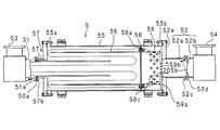
- FIG. 3 is a side sectional view showing an example of the configuration of the recovery device 3.
- the flow part 5 includes an outer cylinder 55, an annular part 57 (second closing part), an upstream inner cylinder 56, a partition plate 58 (first closing part), and a downstream inner cylinder 59. Including. In FIG. 3, the arrow shown with the broken line shows the flow of gas.
- the inflow pipe 51, the outer cylinder 55, the annular portion 57, the upstream inner cylinder 56, the partition plate 58, and the downstream inner cylinder 59 have a circular shape.
- the outer cylinder 55 is larger in diameter and longer than the inflow pipe 51.
- the outer cylinder 55 includes flanges 55a and 55b provided at both ends.
- the annular portion 57 closes the opening on the upstream side of the outer cylinder 55.
- the annular portion 57 has substantially the same diameter as the flange 55a of the outer cylinder 55, and is fastened to the flange 55a with a bolt.
- An opening is provided at the center of the annular portion 57.
- the downstream portion of the inflow pipe 51 passes through an opening provided in the center of the annular portion 57 and is inserted into the outer cylinder 55 coaxially with the outer cylinder 55 from the upstream side.
- a first opening / closing valve 53 is provided at the upstream end of the inflow pipe 51.
- the annular portion 57 includes a cylindrical portion 57a that protrudes upstream around the opening and is provided with a flange 57b at the tip.
- the inflow pipe 51 includes a flange 51a provided on the outer periphery at a predetermined position.
- the flange 57b at the tip of the cylindrical portion 57a and the flange 51a of the inflow pipe 51 are connected via a heat insulating member.
- the flange 57b at the distal end of the cylindrical portion 57a and the flange portion 51a of the inflow pipe 51 are in contact with each other via a heat insulating centering O-ring 50a and fastened by a clamp.
- the downstream inner cylinder 59 is larger in diameter than the inflow pipe 51 and smaller in diameter than the outer cylinder 55.
- a disc part 59 a having a diameter larger than that of the outer cylinder 55 is provided at the downstream end of the downstream inner cylinder 59.
- a plurality of holes 59b are provided in the central part of the disc part 59a.
- a plurality of holes 59 c are also provided in the peripheral wall of the downstream side inner cylinder 59.
- the flange 55b of the outer cylinder 55 is formed with a circular recess for accommodating the disc part 59a of the downstream inner cylinder 59 so as to be fitted therein.
- the downstream inner cylinder 59 is fitted to the outer cylinder 55 on the downstream side of the outer cylinder 55 by fitting the disc portion 59a into the recess formed in the flange 55b.
- the upstream inner cylinder 56 is fastened to the downstream inner cylinder 59 via a partition plate 58 at the upstream end (left end) of the downstream inner cylinder 59.
- the upstream inner cylinder 56 has a diameter substantially equal to that of the downstream inner cylinder 59, and is arranged inside the outer cylinder 55 so as to surround the periphery (outer periphery) of the inflow pipe 51.
- the upstream inner cylinder 56 is arranged coaxially with the outer cylinder 55 and the inflow pipe 51.
- the length in the longitudinal direction of the upstream inner cylinder 56 is set such that a predetermined gap is formed between the upstream end (left end) of the upstream inner cylinder 56 and the annular portion 57. .
- the outer diameter of the partition plate 58 is formed to be substantially the same as or slightly smaller than the inner diameter of the outer cylinder 55, and between the outer cylinder 55 and the upstream inner cylinder 56 and the downstream inner cylinder 59. It is separated. In the outer peripheral portion of the partition wall plate 58, a hole portion 58a for allowing the outer cylinder 55, the upstream inner cylinder 56, and the downstream inner cylinder 59 to flow from the upstream side to the downstream side is formed over the entire circumference. Yes.
- annular (circular shape) cooling ring 52e having an opening at the center is fitted and fixed.
- the cooling ring 52e can be substantially C-shaped.
- the cooling ring 52e and the flange 55b of the outer cylinder 55 are in contact with each other and fastened with bolts.
- the downstream inner cylinder 59 is also fixed to the outer cylinder 55 by bringing the cooling ring 52e and the flange 55b of the outer cylinder 55 into contact with each other and fastening them.
- the discharge pipe 52 is constituted by two first pipe parts 52a and a second pipe part 52b, and between the flange part 52c of the first pipe part 52a and the flange part 52d of the second pipe part 52b. Is provided with an O-ring 50b, and the first tube portion 52a and the second tube portion 52b are fixed to each other.
- the first pipe portion 52a of the discharge pipe 52 is continuously connected to the opening of the cooling ring 52e.
- the cooling ring 52e is configured such that a refrigerant, for example, water supplied from the cooling unit 8 (see FIG. 1) flows, and the cooling unit 52 is configured to cool the cooling ring 52e. .
- the disc part 59a of the downstream inner cylinder 59 is in contact with the cooling part 8 over almost the entire surface.
- the flange 55b of the outer cylinder 55 is in contact with the disc portion 59a.
- the upstream inner cylinder 56 and the downstream inner cylinder 59 are in contact with the partition plate 58. That is, the cooling ring 52 e is in direct or indirect contact with the downstream inner cylinder 59, the partition plate 58, the upstream inner cylinder 56, and the outer cylinder 55.
- the outer cylinder 55, the upstream inner cylinder 56, the partition plate 58, and the downstream inner cylinder 59 of the flow passage portion 5 are made of a material having high thermal conductivity. Therefore, when the cooling ring 52e is cooled, these parts can be cooled.
- the annular portion 57 and the inflow pipe 51 are connected via a centering O-ring 50a having heat insulation properties. Therefore, the inflow pipe 51 can be maintained at a high temperature by heating with the heating unit 7, and the high-temperature heat can be prevented from being transmitted to each part of the flow-through unit 5.
- the annular portion 57 that closes the upstream side of the outer cylinder 55 is provided between the heated inflow pipe 51 and the outer cylinder 55 that is cooled, and serves as a member that insulates each part. Function.
- the temperature of the inflow pipe 51 can be set to a temperature at which the organic ruthenium compound does not re-solidify, for example, 70 ° C. or more.
- the temperature of the inflow pipe 51 can be set to be equal to or lower than a temperature at which the organic ruthenium compound can be stably present without being decomposed, and can be set to, for example, 100 ° C. or lower.
- inflow pipe 51 is heated to about 80 ° C., for example.
- the temperature of the downstream inner cylinder 59, the partition wall plate 58, the upstream inner cylinder 56, and the outer cylinder 55 cooled by the cooling ring 52e can be set to a temperature at which the organic ruthenium compound is not resublimated, for example, 40 ° C. or less. can do. Further, as the refrigerant circulating in the cooling ring 52e, for example, public water of about 20 ° C. can be used.
- a second opening / closing valve 54 is provided at the downstream end of the discharge pipe 52.
- control unit 4 is, for example, a microcomputer having a CPU, a storage unit storing a computer program for controlling the operation of each component of the substrate processing apparatus 100, a temporary storage RAM, and an interface Etc. are connected to the CPU via the bus.
- the CPU controls the operations of the collection apparatus 3 and the film forming apparatus 2 by reading the computer program stored in the storage unit into the RAM and executing it.
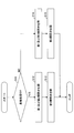
- FIG. 4 is a flowchart showing a processing procedure in which the control unit 4 controls the opening / closing of the first on-off valve 53, the second on-off valve 54, and the third on-off valve 62.
- the control unit 4 when the gas containing the organic ruthenium compound is discharged from the processing chamber 21 of the film forming apparatus 2, the control unit 4 selectively transmits the gas discharged from the processing chamber 21 to the flow passage 5.
- the first on-off valve 53 and the third on-off valve 53 are configured so that the gas discharged from the processing chamber 21 selectively flows into the bypass pipe 61.
- the operation of the valve 62 is controlled.
- the control unit 4 when the gas containing the organic ruthenium compound is discharged from the processing chamber 21 of the film forming apparatus 2, causes the gas to flow out from the flow-through unit 5 and the gas containing the organic ruthenium compound from the processing chamber 21.
- the operation of the second on-off valve 54 is controlled so that the gas does not flow out from the flow passage portion 5.
- control unit 4 stores data for managing the operation of the film forming apparatus 2 in a storage unit or a RAM.
- the control unit 4 determines whether the substrate is currently being processed using the data (step S11).
- step S11 If it is determined that the substrate is being processed (step S11: YES), the controller 4 causes the first on-off valve 53 and the second on-off valve so that the first on-off valve 53 and the second on-off valve 54 are opened. Then, the operation of the third on-off valve 62 is controlled so that the third on-off valve 62 is closed (step S13), and the processing is ended. Thereby, the gas discharged from the processing chamber 21 of the film forming apparatus 2 is selectively introduced into the flow passage 5 via the inflow pipe 51, and the gas from which the organic ruthenium compound is removed in the flow passage 5 is obtained. It is discharged from the discharge pipe 52. At this time, in the source gas supply unit 1, the bypass on-off valve 19 can be closed and the carrier gas on-off valve 13 and the on-off valve 16 can be opened. As a result, the source gas is supplied to the film forming apparatus 2.
- step S11 when it is determined in step S11 that the substrate processing is not being performed (step S11: NO), that is, when it is determined that the film forming apparatus 2 is idling during maintenance or the like, the control unit 4 includes the first on-off valve.
- the operations of the first on-off valve 53 and the second on-off valve 54 are controlled so that the 53 and the second on-off valve 54 are closed (step S14), and then the third on-off valve 62 is opened. Then, the operation of the third on-off valve 62 is controlled (step S15), and the process ends.
- the gas discharged from the film forming apparatus 2 selectively flows into the bypass pipe 61 and is discharged while bypassing the flow passage portion 5.
- the carrier gas on-off valve 13 and the on-off valve 16 can be closed and the bypass on-off valve 19 can be opened. As a result, only the carrier gas containing no raw material is supplied to the film forming apparatus 2.
- control of the first on-off valve 53 and the second on-off valve 54 and the control of the third on-off valve 62 may be executed in reverse order.
- the gas exhausted from the processing chamber 21 flows into the flow passage 5 through the heated inflow pipe 51 as shown in FIG. Since the inflow pipe 51 is heated to about 80 ° C., the organic ruthenium compound does not adhere to the inflow pipe 51.
- the gas that has flowed into the flow passage 5 flows in the right direction in the drawing and is turned back by the partition wall plate 58, flows between the inflow pipe 51 and the upstream inner cylinder 56 in the left direction in the drawing, and the annular portion 57. Then, it turns back again and flows between the outer cylinder 55 and the upstream inner cylinder 56 in the right direction in the figure.
- the gas exhausted from the processing chamber 21 is condensed on the inner peripheral surface and outer peripheral surface of the cooled upstream inner cylinder 56, the partition wall plate 58, and the inner peripheral surface of the outer cylinder 55, and solid organic ruthenium is formed on these wall surfaces. Compound adheres.
- the inflow pipe 51 and the upstream inner cylinder 56 are walls that allow the gas flowing into the flow passage 5 to be discharged to the discharge pipe 52 after meandering through the flow passage 5. Function. As described above, the gas meanders and moves in the flow passage portion 5, thereby increasing the distance that the gas moves in the flow passage portion 5, thereby increasing the amount of the organic ruthenium compound deposited.
- the gas flowing between the outer cylinder 55 and the upstream inner cylinder 56 flows through the hole 58 a of the partition plate 58 and the holes 59 c and 59 b of the downstream inner cylinder 59 from the discharge pipe 52. Exhausted. Most of the organic ruthenium compound contained in the gas is removed when it flows between the outer cylinder 55 and the upstream inner cylinder 56, but the remaining organic ruthenium compound is also removed from the downstream inner cylinder 59. Captured at. In the present embodiment, since the hole 58a of the partition wall plate 58 and the holes 59c and 59b of the downstream inner cylinder 59 are provided on the downstream side in the flow passage 5, the organic matter precipitated in the flow passage 5 is provided. The ruthenium compound can be easily collected in the flow passage portion 5.
- the unreacted organic ruthenium compound is recovered from the gas exhausted from the processing chamber 21 with a simple configuration, and the recovered organic ruthenium compound is prevented from being sublimated and exhausted when the film forming apparatus 2 is idle. be able to.
- the recovered organic ruthenium compound can be reused as a valuable resource.
- the organic ruthenium compound contained in the gas discharged from the processing chamber 21 is recovered by the recovery device 3, it can be prevented that the organic ruthenium compound included in the raw material gas is condensed in the exhaust line and the dry pump. Moreover, when providing an exclusion apparatus in the back
- the first on-off valve 53 and the second on-off valve 54 are closed, and the third on-off valve 62 is opened. Therefore, when a gas that does not contain an organic ruthenium compound is discharged from the processing chamber 21 of the film forming apparatus 2, the gas does not flow through the flow passage 5 but is exhausted through the bypass pipe 61. Therefore, it is possible to prevent the gas containing no organic ruthenium compound from flowing through the flow passage 5 during idling of the film forming apparatus 2 and exhausting the once captured organic ruthenium compound to the outside.
- organic ruthenium compounds have the property of destabilizing and decomposing unless carbon monoxide is allowed to flow as a carrier gas in a reduced pressure atmosphere.
- the recovery device 3 of the present embodiment when there is a possibility that the inside of the flow passage portion 5 is exposed to the reduced pressure atmosphere, the first open / close valve 53 and the second open / close valve 54 are closed, thereby reducing the reduced pressure atmosphere. It is possible to prevent the organic ruthenium compound captured by the flow passage 5 from being decomposed.
- the organic ruthenium compound can be efficiently recovered from the gas exhausted from the processing chamber 21. Further, it is possible to prevent the organic ruthenium compound once trapped in the flow passage 5 from being sublimated again by the gas flow and exhausted to the outside.
- the inflow pipe 51 is maintained at a high temperature, it is possible to prevent the organic ruthenium compound from condensing in the inflow pipe 51 and its upstream side.
- FIG. 5 is a side sectional view showing a configuration example of the recovery device 3 of the first modification.
- the recovery device 3 of Modification 1 has the same configuration as that of the above-described embodiment described with reference to FIG. 3, but between the first pipe portion 52 a and the second pipe portion 52 b that constitute the discharge pipe 52. Is different in that a mesh 150a is provided.
- the mesh 150a is provided so as to allow the gas to pass therethrough and not allow the deposited organic ruthenium compound to pass therethrough.
- a center ring 150b with a mesh 150a is provided between the first tube portion 52a and the second tube portion 52b.
- FIG. 6 is a side sectional view showing a configuration example of the recovery device 3 according to the second modification.
- the recovery device 3 of Modification 2 has the same configuration as that of the above-described embodiment described with reference to FIG. 3, but between the first pipe portion 52 a and the second pipe portion 52 b that constitute the discharge pipe 52. Furthermore, the point that a flow control orifice 205b with a flow control function is provided is different from the embodiment.
- the flow control orifice 205b has an orifice plate that is urged to bend toward the upstream side and has a hole (not shown) at the center, as indicated by the broken line in the figure.
- the orifice plate of the flow control orifice 205b bends against the urging force and closes the discharge pipe 52.
- a hole is formed in the central portion of the orifice plate of the flow control orifice 205b, a certain amount of gas flows.
- the orifice plate when the flow rate of the gas flowing through the flow passage 5 is large, the orifice plate is pushed downstream against the urging force, and the discharge pipe 52 is blocked. However, gas flows only from the hole (not shown) of the orifice plate. On the other hand, when the flow rate of the gas flowing through the flow passage 5 is small, the force for pushing the orifice plate to the downstream side does not work, so that the orifice plate is deflected to the upstream side by the urging force as shown by the broken line in the drawing, Is greatly open. By providing such an orifice plate, the flow rate of the gas flowing through the flow passage 5 can be limited to a certain value or less.
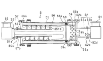
- FIG. 7 is a side sectional view showing a configuration example of the recovery device 3 according to the third modification.
- the recovery device 3 of Modification 3 has a collision plate 351b formed in a spiral shape on the outer peripheral surface of the inflow pipe 51 so as to block the flow of gas in the flow passage 5.
- the collision plate 351b is formed when the gas flowing into the upstream inner cylinder 56 flowing in from the inflow pipe 51 turns back at the partition plate 58 and moves to the left in the drawing along the inner peripheral surface of the upstream inner cylinder 56. In addition, it is provided so as to move spirally along the collision plate 351b.
- the gas discharged from the processing chamber 21 of the film forming apparatus 2 flows into the upstream inner cylinder 56 from the inflow pipe 51 and flows into the upstream inner cylinder 56.
- the time for which the organic ruthenium compound contained in gas stagnates in the flow-through part 5 can be lengthened. Thereby, the contact probability with the upstream inner cylinder 56 etc. cooled to the temperature which can be condensed can be raised.
- the collision plate 351b is also configured so that the gas that has flowed into the flow passage 5 is discharged to the discharge pipe 52 after meandering through the flow passage 5.
- the gas meanders and moves in the flow passage portion 5, thereby increasing the distance that the gas moves in the flow passage portion 5, thereby increasing the amount of the organic ruthenium compound deposited.
- organic ruthenium can be recovered more effectively from the gas discharged from the processing chamber 21 of the film forming apparatus 2.
- the spiral collision plate 351b has been described.
- the shape of the collision plate 351b is not particularly limited as long as the contact probability of the gas flowing through the flow passage 5 is increased.
- a configuration similar to that of the collision plate 351b can be introduced so that the gas moves spirally also in the region between the upstream inner cylinder 56 and the outer cylinder 55.
- the first on-off valve 53 and the third on-off valve 62 are provided on the downstream side where the bypass pipe 61 branches from the inflow pipe 51.
- the first on-off valve 53 and the third on-off valve 62 may be configured by a three-way valve, for example, and the bypass pipe 61 may be provided at a branch point where the inflow pipe 51 branches. In such a configuration, the gas containing the raw material can be prevented from flowing into the bypass pipe 61, and the upstream portion of the bypass pipe 61 need not be heated by the heating unit 7.
- the bypass pipe 61 is joined to the discharge pipe 52 on the downstream side of the second on-off valve 54, but the bypass pipe 61 is connected to the discharge pipe.
- the gas that has passed through the bypass pipe 61 may be discharged separately from the discharge pipe 52 without joining the 52.
- the second opening / closing valve 54 may not be provided.
- the substrate processing apparatus 100 and the recovery apparatus 3 of the present embodiment are organometallic compounds other than the organoruthenium compound. It can also be applied to.
- organometallic compound examples include W (CO) 6 , Ni (CO) 4 , Mo (CO) 6 , Co 2 CO) 8 , Rh 4 (CO) 12 , Re 2 (CO) 10 , Cr (CO) 6 , A carbonyl-based organometallic compound made of one or more materials selected from the group consisting of Os 3 (CO) 12 and Ta (CO) 5 can be used.
- the temperature at which the reservoir heating unit 11b heats the solid raw material 10 the temperature at which the heating unit 7 heats the inflow pipe 51, etc., the temperature at which the cooling unit 8 cools the flow-through unit 5, etc. It can be set accordingly.
- the gas exhausted from the processing chamber 21 of the film forming apparatus 2 flows through the flow part 5. Since the flow part 5 is cooled by the cooling part 8, the organometallic compound such as the organoruthenium compound contained in the gas is condensed and captured. By closing the first on-off valve 53 and the second on-off valve 54, it is possible to prevent the organometallic compound once captured by the flow passage portion 5 from being sublimated again and exhausted to the outside. In addition, when the first on-off valve 53 and the second on-off valve 54 are closed, by opening the third on-off valve 62 of the bypass pipe 61, the gas discharged from the processing chamber 2 is allowed to pass through the bypass pipe 61. Can flow downstream.
- the inflow pipe 51 is heated by the heating unit 7, it is possible to prevent the organometallic compound from adhering to the upstream side portion of the flow-through unit 5.
- the substrate processing apparatus 100 of the present embodiment when the substrate processing is performed in the processing chamber 21 of the film forming apparatus 2, the first on-off valve 53 and the second on-off valve 54 are open, and the third on-off valve 62 is closed. Accordingly, the gas exhausted from the processing chamber 21 flows through the flow passage 5, and the organometallic compound contained in the gas is captured.
- the first on-off valve 53 and the second on-off valve 54 are closed, and the third on-off valve 62 is opened. Therefore, when a gas other than the source gas, for example, a carrier gas, is discharged from the processing chamber 21 as a purge gas, the gas flows downstream through the bypass pipe 61 without flowing through the flow passage 5.
- a gas other than the source gas for example, a carrier gas
- the first on-off valve 53 and the second on-off valve 54 are opened, and the third on-off valve 62 is closed. It is good. In this case, there is a possibility that a large amount of organometallic compound is contained in the gas discharged from the film forming apparatus 2, but the gas discharged from the film forming apparatus 2 flows into the flow-through portion 5 and flows through the flow-through portion 5. Can be recovered.
- the mesh 150a constituted by the center ring 150b with the mesh 150a and the like is provided in the middle of the discharge pipe 52, so that it remains in the gas discharged from the flow passage portion 5.
- the organometallic compound is captured by the mesh 150a.
- the gas discharged from the processing chamber 21 of the film forming apparatus 2 is once captured by the flow passage 5 by restricting the flow rate through the flow passage 5. It is possible to prevent the organometallic compound from being exhausted to the outside by the gas flow.
- the gas flowing into the flow passage 5 through the inflow pipe 51 flows between the inflow pipe 51 and the upstream inner cylinder 56, and then the upstream inner cylinder 56. And is discharged from the outer cylinder 55.
- the organometallic compound contained in the gas is cooled and condensed by flowing between the inflow pipe 51, the upstream inner cylinder 56, and the outer cylinder 55, and the upstream inner cylinder 56 or the outer cylinder 55 Captured by the surrounding wall.
- the flow rate of the gas flowing through the gap between the outer cylinder 55 and the upstream inner cylinder 56 can be restricted, and the organometallic compound once captured by the flow passage 5 Can be prevented from being exhausted to the outside by the gas flow.
- the organic ruthenium compound that is, for example, Ru 3 (CO) 12 can be captured by the flow-through portion 5.
- the inflow pipe 51 is heated in a temperature range of 70 ° C. or higher and 100 ° C. or lower. By heating the inflow pipe 51 to 70 ° C. or higher, it is possible to prevent the Ru 3 (CO) 12 from re-condensing, and by suppressing the temperature at which the inflow pipe 51 is heated to 100 ° C. or lower, Ru 3 (CO) It can prevent that 12 decomposes
- the flow part 5 has a collision plate 351b provided so that the gas that has flowed in flows spirally. Therefore, the gas that has flowed into the flow passage portion 5 flows while colliding with the collision plate 351b. Accordingly, the probability that the vaporized organometallic compound contacts the collision plate 351b can be improved by extending the flow path. Further, since the collision plate 351b is spiral, a centrifugal force acts on the flowing gas, and a vortex flow is generated in a region surrounded by the inner wall (upstream inner cylinder 56) of the flow passage portion 5 and the collision plate 351b. Forming and effectively retaining the gas in the region.
- the unreacted organometallic compound is recovered from the gas exhausted from the processing chamber 21 with a simple configuration, and the recovered organometallic compound is sublimated and exhausted when the film forming apparatus 2 is idling. Can be prevented.
Landscapes
- Chemical & Material Sciences (AREA)
- General Chemical & Material Sciences (AREA)
- Chemical Kinetics & Catalysis (AREA)
- Engineering & Computer Science (AREA)
- Materials Engineering (AREA)
- Mechanical Engineering (AREA)
- Metallurgy (AREA)
- Organic Chemistry (AREA)
- Chemical Vapour Deposition (AREA)
- Electrodes Of Semiconductors (AREA)
Abstract
基板処理装置は、有機金属化合物を含む原料ガスを用いて基板処理を行う処理室と、有機金属化合物を回収する回収装置を含む。回収装置は、処理室から排出されたガスが通流する通流部、通流部に流入したガスに含まれる未反応の有機金属化合物を通流部内で析出させるよう該通流部を冷却する冷却部、通流部の上流側と下流側とを連通するバイパス路、通流部の上流側に設けられ、処理室から排出されたガスの通流部への流入を許可または阻止する第1開閉部、通流部の上流側に設けられ、処理室から排出されたガスのバイパス路への流入を許可または阻止するバイパス路開閉部、および通流部の下流側に設けられた排出管を含む。
Description
本発明は、回収装置、及び該回収装置を備えた基板処理装置に関し、とくに基板処理を行う処理室より排出されたガスから、該ガスに含まれる未反応の有機金属化合物を回収する回収装置、及び該回収装置を備えた基板処理装置に関する。
半導体デバイスの成膜処理装置の一つとしてCVD(Chemical Vapor Deposition)装置が利用されている。CVD装置は、原料ガスをウェハが載置された処理室に供給し、処理室内で原料ガスを反応させることによってウェハ上に薄膜を形成する装置である。CVD装置の成膜処理(基板処理)で発生した副生成物及び未反応の原料ガス等は、処理室外へ排気される。排気された副生成物及び未反応の原料ガス等がそのまま大気中に放出されると環境汚染等の原因となる。そのため、排気系に設けられた捕獲装置によってこれらの副生成物及び原料ガスを捕獲して除去するようにしてある。
特許文献1には、処理室から排気されたガスを冷媒と接触させることにより未反応の原料ガスを凝固させて原料を再析出させる凝固ユニットと、凝固ユニット内の冷媒を濾過することにより再析出された原料を冷媒から分離して回収する濾過回収ユニットとで構成された捕獲装置が開示されている。
特許文献2には、処理室から排気されたガスを高温に曝して排気ガス中に含まれる未反応の原料ガスを熱分解させて原料ガス中に含まれている金属を付着させる捕集部材を有する捕獲装置が開示されている。
特許文献3には、処理室から排気されたガスを通過させる排気通路が形成された複数の排気捕集ユニットを直列に配置してなる捕獲装置が開示されている。排気捕集ユニットは、ガスの流れを遮るように配置された複数の衝突板を有する。
しかしながら、特許文献1の捕獲装置においては、冷媒を循環させ、冷媒に接触して析出した未反応の原料を冷媒から濾過するなどの処理が必要であり、装置構成が複雑で高コストであるという問題があった。
特許文献2の捕獲装置においては、処理室から排気されたガスを高温に曝して排気ガス中に含まれる未反応の原料ガスを熱分解させる構成であり、やはり装置構成が複雑で高コストであるという問題があった。
また、特許文献2に記載の方法においては未反応の原料ガスが金属の状態で回収されるが、金属の状態で回収すると再精製にコストを要するという問題があった。
特許文献3の捕獲装置においては、処理装置のアイドリング時に処理室から排気されるガスが捕獲装置に流入した場合、捕獲された原料の一部が昇華し、外部へ排気されるという問題があった。
本発明はかかる事情に鑑みてなされたものであり、処理室より排気されたガスから、未反応の有機金属化合物を簡単な構成で回収し、回収された有機金属化合物が処理装置のアイドリング時に昇華して排気されることを防止することができる基板処理装置及び回収装置を提供することを目的とする。
一実施形態の基板処理装置は、有機金属化合物を含む原料ガスを用いて基板処理を行う処理室と、有機金属化合物を回収する回収装置を含む。回収装置は、処理室から排出されたガスが通流する通流部、通流部に流入したガスに含まれる未反応の有機金属化合物を通流部内で析出させるよう該通流部を冷却する冷却部、通流部の上流側と下流側とを連通するバイパス路、通流部の上流側に設けられ、処理室から排出されたガスの通流部への流入を許可または阻止する第1開閉部、通流部の上流側に設けられ、処理室から排出されたガスのバイパス路への流入を許可または阻止するバイパス路開閉部、および通流部の下流側に設けられた排出管を含む。
一実施形態の回収装置は、有機金属化合物を含む原料ガスを用いて基板処理を行う処理室から排出された原料ガスが通流する通流部と、通流部に流入したガスに含まれる未反応の有機金属化合物を通流部内で析出させるよう該通流部を冷却する冷却部と、通流部の上流側と下流側とを連通するバイパス路と、通流部の上流側に設けられ、処理室から排出されたガスの通流部への流入を許可または阻止する第1開閉部と、通流部の上流側に設けられ、処理室から排出されたガスのバイパス路への流入を許可または阻止するバイパス路開閉部と、および通流部の下流側に設けられた排出管とを含む。
以下、本発明をその実施の形態を示す図面に基づいて詳述する。
尚、すべての図面において、同様な構成要素には同様の符号を付し、適宜説明を省略する。
以下の実施の形態において、有機金属化合物が有機ルテニウム化合物であり、キャリアガスとしてCO(一酸化炭素)を用いてRu金属膜よりなる薄膜をウェハ上に成膜する場合を例として説明する。
図1は、本実施の形態の基板処理装置100の一構成例を示すブロック図である。
本実施の形態の基板処理装置100は、気化した有機ルテニウム化合物を含む原料ガスを供給する原料ガス供給部1と、原料ガス供給部1より供給された原料ガスを用いて基板の成膜処理(基板処理)を行う成膜装置2と、成膜装置2から排出されたガスから未反応の有機ルテニウム化合物を回収する回収装置3と、各構成部の動作を制御する制御部4とを備える。
図2は、原料ガス供給部1及び成膜装置2の一構成例を模式的に示す側断面図である。
成膜装置2は、筒体状の処理室21と、処理室21内に設けられ、ウェハWを保持する保持手段22と、ゲートバルブ23と、処理室21の天井部に設けられたシャワーヘッド24とを含む。
保持手段22は、処理室21の底部に立設された支柱22aと、支柱22aにより支持された円板状の載置台22bと、ウェハWを加熱するように構成された加熱部22cとを有する。載置台22b上には、ウェハWが載置される。載置台22bは、例えばAlN(窒化アルミニウム)等のセラミック材より構成される。加熱部22cは、載置台22b内部に設けられた構成とすることができる。この場合、加熱部22cは、例えばタングステンワイヤ等より構成される。
処理室21は、例えばアルミニウム合金等より構成される。処理室21は、底部に設けられた排気口21aと、側壁に設けられ、ウェハWを搬出入するための開口21bとを含む。排気口21aには、後述する排気系26が接続されて、処理室21内を減圧雰囲気にすることができるように構成される。ゲートバルブ23は、開口21bを気密に開閉するように設けられる。
シャワーヘッド24は、ガス入口24aと、下面に設けられたガス噴出孔25とを含む。シャワーヘッド24は、ガス噴出孔25から処理室21内へ成膜処理に必要な原料ガスを供給するように構成される。
原料ガス供給部1は、固体原料10を貯留する原料貯留部11と、原料貯留部11内に設けられた多孔板11aと、原料貯留部11を加熱するための貯留部加熱部11bと、原料貯留部11にキャリアガスを供給するためのキャリアガス管14と、キャリアガス管14に設けられた流量制御器12およびキャリアガス開閉弁13と、原料貯留部11内で気化された原料ガスを送出するガス出口15と、原料貯留部11のガス出口15と成膜装置2とを接続する原料通路17と、原料通路17に設けられた開閉弁16と、バイパス管18と、バイパス開閉弁19とを含む。
固体原料10は、成膜処理に用いる有機金属化合物を含む。本実施の形態において、固体原料10は、有機ルテニウム化合物、例えばRu3(CO)12を含む。この場合、固体原料10は、一般的には蒸気圧が非常に低くて蒸発し難い特性を有している。また、成膜反応に寄与する量は非常に少なく、90%程度の有機金属化合物が未反応状態でキャリアガスであるCOとともに、排気される。
ガス出口15は、原料貯留部11の天井部に設けられる。原料通路17は、一端が原料貯留部11のガス出口15に接続され、他端が成膜装置2のシャワーヘッド24のガス入口24aに接続されて原料ガス供給部1と成膜装置2とを接続する。原料貯留部11で発生した原料ガスは、原料通路17を介して成膜装置2に供給できるようになっている。開閉弁16は、原料通路17の原料貯留部11に近い部分に設けられている。
キャリアガス管14は、原料貯留部11の下面側に設けられる。流量制御器12は、たとえばマスフローコントローラとすることができる。キャリアガス開閉弁13は、流量制御器12と原料貯留部11との間に設けられる。
多孔板11aは、原料貯留部11内部のキャリアガス管14が設置された側の近傍に設置される。多孔板11aには複数の孔部が設けられ、固体原料10は、多孔板11aの上に保持される。このような構成において、キャリアガス管14から供給されたキャリアガスは、多孔板11aの孔部を介して、原料貯留部11内に均一に供給される。キャリアガスとしてここではCO(一酸化炭素)ガスを用いることができる。
原料貯留部11は、たとえばタンクとすることができる。貯留部加熱部11bは、原料貯留部11を構成するタンク全体を覆うようにして設けられており、固体原料10の気化を促進させるようになっている。貯留部加熱部11bが固体原料10を加熱する温度は、有機ルテニウム化合物が分解せずに安定的に存在できる温度、例えば約80℃程度とすることができる。
バイパス管18は、キャリアガス管14のキャリアガス開閉弁13よりも上流側(流量制御器12に近い側)と原料通路17の開閉弁16の下流側とを連通する。バイパス開閉弁19はバイパス管18に設けられ、必要に応じてキャリアガスを原料貯留部11をバイパスさせて成膜装置2に流すことができるようになっている。
また、原料ガス供給部1は、原料通路17に設けられた、テープヒータ等の加熱部(図示せず)をさらに含み、加熱部により原料通路17を加熱して原料ガスが再固化することを防止するようになっている。
以上のような構成の原料ガス供給部1において、原料ガス供給部1から成膜装置2に原料ガスを供給する場合、バイパス開閉弁19でバイパス管18を閉じるとともに、キャリアガス開閉弁13および開閉弁16を開く。この状態で、流量制御器12およびキャリアガス開閉弁13により、キャリアガスを流量制御しつつ原料貯留部11に供給して、貯留部加熱部11bにより固体原料10を加熱することにより、原料貯留部11内で固体原料10が気化され、原料ガスが形成される。原料貯留部11内で形成された原料ガスは成膜装置2に供給される。
一方、原料ガス供給部1から成膜装置2にキャリアガスのみを供給する場合は、キャリアガス開閉弁13および開閉弁16を閉じてキャリアガス管14へのキャリアガスの流れを閉じ、バイパス開閉弁19を開く。これにより、原料を含まないキャリアガスのみが成膜装置2に供給されるようになる。
排気系26は、成膜装置2の処理室21の排気口21aに接続された排気通路26aと、排気通路26aに上流側から下流側にこの順で設けられた圧力調整弁26b、真空ポンプ部26c、通路加熱ヒータ26dおよび回収装置3とを含む。成膜装置2の処理室21内のガスは、排気通路26aを通じて排気されるように構成されている。回収装置3の更に下流側には図示しないドライポンプが設けられている。
圧力調整弁26bは例えばバタフライ弁よりなり、処理室21内の圧力を調整する機能を有している。ターボ分子ポンプ26c及びドライポンプによって処理室21内の雰囲気を真空引きできるようになっている。この場合、成膜時の設定プロセス圧力に応じて、ターボ分子ポンプ26c及びドライポンプの内のいずれか一方のみを設けるようにしてもよい。
通路加熱ヒータ26dは、排気通路26aに沿って設けられ、排気通路26aに未反応の有機ルテニウム化合物が凝縮することを防止している。
図1に示すように、回収装置3は、成膜装置2の処理室21から排出されたガスが通流する通流部5と、成膜装置2の処理室21から排出されたガスを通流部5へ流入させる流入管51と、通流部5へ流入したガスから有機ルテニウム化合物が回収されたガスを排出する排出管52と、流入管51及び排出管52にそれぞれ設けられた第1開閉弁53(第1開閉部)及び第2開閉弁54(第2開閉部)と、通流部5の上流側と、下流側とを連通するバイパス管61(バイパス路)と、バイパス管61に設けられた第3開閉弁62(バイパス路開閉部)と、加熱部7と、冷却部8とを含む。
通流部5は、たとえばステンレス製又はアルミニウム製等、熱伝導性の高い材料により構成することができる。
第1開閉弁53は、流入管51(通流部5の上流側)を開閉し、成膜装置2の処理室21から排出されたガスの流入管51(通流部5)への流入を許可または阻止する。第2開閉弁54は、排出管52(通流部5の下流側)を開閉し、排出管52(通流部5)からのガスの流出を許可または阻止する。第1開閉弁53及び第2開閉弁54は、例えば、空気式制御弁、電磁弁などとすることができ、後述する制御部4によって制御される。
第3開閉弁62は、バイパス管61を開閉し、成膜装置2の処理室21から排出されたガスのバイパス管61へ流入を許可または阻止する。第3開閉弁62も、例えば、空気式制御弁、電磁弁などとすることができ、後述する制御部4によって制御される。
加熱部7は、流入管51、第1開閉弁53、バイパス管61の第3開閉弁62よりも上流側部分、及び第3開閉弁62を加熱する。加熱部7は、有機ルテニウム化合物が再固化しないとともに、分解せずに安定的に存在できる温度、例えば約80℃で、これらの部分を加熱する。加熱部7は、例えば、流入管51及びバイパス管61を加熱するマントルヒータならびに第1開閉弁53及び第3開閉弁62を加熱するカートリッジヒータにより構成することができる。
冷却部8は、例えば冷媒を通流させることによって、通流部5を冷却する。加熱部7及び冷却部8の動作は後述の制御部4によって制御される。
本実施の形態において、通流部5は、通流部5内に流入したガスが、通流部5内を蛇行した後に排出管52に排出されるように、通流部5内に設けられた壁部を含む。通流部5の具体的な構成を説明する。
図3は、回収装置3の一構成例を示す側断面図である。
通流部5は、外筒55と、円環部57(第2の閉鎖部)と、上流側内筒56と、隔壁板58(第1の閉鎖部)と、下流側内筒59とを含む。図3中、破線で示した矢印はガスの流れを示す。
ここで、流入管51と、外筒55と、円環部57と、上流側内筒56と、隔壁板58と、下流側内筒59は、円形形状を有する。
外筒55は、流入管51より直径が大きく、長さも長い。外筒55は、両端部に設けられたフランジ55aおよび55bを含む。円環部57は、外筒55の上流側の開口を閉鎖する。円環部57は、外筒55のフランジ55aと略同径であり、フランジ55aにボルトで締結されている。円環部57の中央部には、開口が設けられている。
流入管51の下流側部分は、円環部57の中央部に設けられた開口を貫通して、外筒55内に、上流側から外筒55と同軸に挿入される。流入管51の上流側端部には第1開閉弁53が設けられている。
円環部57は、開口周囲で上流側へ突出し、先端部にフランジ57bが設けられた筒部57aを含む。流入管51は、所定の位置で外周に設けられた鍔部51aを含む。筒部57aの先端部のフランジ57bと、流入管51の鍔部51aとは、断熱部材を介して接続されている。具体的には、筒部57aの先端部のフランジ57bと、流入管51の鍔部51aとは、断熱性のセンタリングOリング50aを介して当接し、クランプによって締結されている。
下流側内筒59は、流入管51より直径が大きく、外筒55よりも直径が小さい。下流側内筒59の下流側の端部には、外筒55よりも直径が大きい円板部59aが設けられている。円板部59aの中央部には、複数の孔部59bが設けられている。下流側内筒59の周壁にも複数の孔部59cが設けられている。ここで、外筒55のフランジ55bには、下流側内筒59の円板部59aを嵌合可能に収容する円状の凹部が形成されている。下流側内筒59は、円板部59aがフランジ55bに形成された凹部に嵌合することにより、外筒55の下流側で外筒55に嵌合される。
上流側内筒56は、下流側内筒59の上流側端部(左端部)で、隔壁板58を介して下流側内筒59と締結されている。上流側内筒56は、下流側内筒59と略等しい直径を有し、流入管51の周囲(外周)を囲むように外筒55の内側に配されている。上流側内筒56は、外筒55及び流入管51と同軸に配されている。上流側内筒56の長手方向の長さは、上流側内筒56の上流側端部(左端部)と、円環部57との間に所定の間隙が形成されるように設定されている。隔壁板58の外径は、外筒55の内径と略同一又は外筒55の内径よりも僅かに小さく形成され、外筒55と、上流側内筒56及び下流側内筒59との間を隔てている。隔壁板58の外周部分には、外筒55と、上流側内筒56及び下流側内筒59との間を上流側から下流側へ通流させる孔部58aが全周に亘って形成されている。
排出管52の上流側端部には、中央部に開口が設けられた環状(円形形状)の冷却リング52eが嵌合固定されている。冷却リング52eは、略C字状とすることもできる。該冷却リング52eと、外筒55のフランジ55bとが当接し、ボルトで締結されている。冷却リング52eと、外筒55のフランジ55bとを当接させ締結することによって、下流側内筒59も外筒55に固定される。
また、排出管52は、2つの第1管部52a及び第2管部52bによって構成されており、第1管部52aの鍔部52cと、第2管部52bの鍔部52dとの間には、Oリング50bが設けられ、第1管部52a及び第2管部52bが互いに固定されている。排出管52の第1管部52aは、冷却リング52eの開口に連続して接続されている。
冷却リング52eには、冷却部8(図1参照)から供給された冷媒、例えば水が通流するように構成されており、冷却部8によって冷却リング52eが冷却されるように構成されている。
本実施の形態において、下流側内筒59の円板部59aは、ほぼ全面にわたって冷却部8と接している。また、外筒55のフランジ55bは円板部59aと接している。また、上流側内筒56および下流側内筒59は、それぞれ隔壁板58に接している。つまり、冷却リング52eは、下流側内筒59、隔壁板58、上流側内筒56、外筒55に直接又は間接的に接触している。本実施の形態において、通流部5の外筒55、上流側内筒56、隔壁板58、および下流側内筒59は、熱伝導性の高い材料により構成されている。そのため、冷却リング52eが冷却されると、これらの各部を冷却することができる。
一方、円環部57と、流入管51との間は、断熱性を有するセンタリングOリング50aを介して接続されている。そのため、流入管51を加熱部7で加熱することにより高温に維持するとともに、この高温の熱が通流部5の各部に伝わらないようにすることができる。
なお、外筒55の上流側を閉鎖している円環部57は、加熱されている流入管51と、冷却されている外筒55との間に設けられており、各部を断熱する部材として機能する。
流入管51の温度は、有機ルテニウム化合物が再固化しない温度以上とすることができ、たとえば70℃以上とすることができる。また、流入管51の温度は、有機ルテニウム化合物が分解せず安定して存在し得る温度以下とすることができ、たとえば100℃以下とすることができる。本実施の形態において、流入管51は、たとえば約80℃に加熱される。
冷却リング52eにより冷却される下流側内筒59、隔壁板58、上流側内筒56および外筒55の温度は、有機ルテニウム化合物が再昇華しない温度以上とすることができ、たとえば40℃以下とすることができる。また、冷却リング52eに巡回させる冷媒としては、たとえば20℃程度の公共水を用いることができる。
排出管52の下流側端部には第2開閉弁54が設けられている。
図1に戻り、制御部4は、例えば、CPUを有するマイクロコンピュータであり、基板処理装置100の各構成部の動作を制御するためのコンピュータプログラムを記憶した記憶部、一時記憶用のRAM、インタフェース等がバスを介してCPUに接続されている。CPUは、前記記憶部が記憶するコンピュータプログラムをRAMに読み出して実行することにより、回収装置3及び成膜装置2の動作を制御する。
図4は、制御部4が第1開閉弁53、第2開閉弁54および第3開閉弁62の開閉を制御する処理手順を示したフローチャートである。
以下では、回収装置3の制御部分について説明する。
本実施の形態において、制御部4は、成膜装置2の処理室21から有機ルテニウム化合物を含むガスが排出される場合に、処理室21から排出されたガスが通流部5に選択的に流入し、処理室21から有機ルテニウム化合物を含むガスが排出されない場合に、処理室21から排出されたガスがバイパス管61に選択的に流入するよう、第1の開閉弁53および第3の開閉弁62の動作を制御する。また、制御部4は、成膜装置2の処理室21から有機ルテニウム化合物を含むガスが排出される場合に、通流部5からガスが流出され、処理室21から有機ルテニウム化合物を含むガスが排出されない場合に、通流部5からガスが流出されないよう、第2の開閉弁54の動作を制御する。
具体的には、制御部4は、成膜装置2の動作を管理するためのデータを記憶部又はRAMに記憶している。制御部4は、該データを用いて、現在、基板処理中であるか否かを判定する(ステップS11)。
基板処理中であると判定した場合(ステップS11:YES)、制御部4は、第1開閉弁53及び第2開閉弁54が開状態となるように、第1開閉弁53及び第2開閉弁54の動作を制御し(ステップS12)、次いで、第3開閉弁62が閉状態となるように、第3開閉弁62の動作を制御して(ステップS13)、処理を終える。これにより、成膜装置2の処理室21から排出されるガスが流入管51を介して通流部5内に選択的に流入され、通流部5内で有機ルテニウム化合物が取り除かれたガスが排出管52から排出される。なお、このとき、原料ガス供給部1では、バイパス開閉弁19を閉じて、キャリアガス開閉弁13および開閉弁16を開いておくことができる。これにより、原料ガスが成膜装置2に供給されるようになる。
一方、ステップS11で基板処理中で無いと判定した場合(ステップS11:NO)、つまり、成膜装置2がメンテナンス時等のアイドリング中であると判定した場合、制御部4は、第1開閉弁53及び第2開閉弁54が閉状態となるように、第1開閉弁53及び第2開閉弁54の動作を制御し(ステップS14)、次いで、第3開閉弁62が開状態となるように、第3開閉弁62の動作を制御して(ステップS15)、処理を終える。これにより、成膜装置2から排出されるガスは、バイパス管61に選択的に流入され、通流部5を迂回して排出される。なお、このとき、原料ガス供給部1では、キャリアガス開閉弁13および開閉弁16を閉じて、バイパス開閉弁19を開いておくことができる。これにより、原料を含まないキャリアガスのみが成膜装置2に供給されるようになる。
なお、言うまでもなく、第1開閉弁53及び第2開閉弁54の制御と、第3開閉弁62の制御とを逆順で実行しても良い。
本実施の形態の回収装置3及び基板処理装置100によれば、処理室21より排気されたガスは、図3に示すように、加熱された流入管51を通じて、通流部5に流入する。流入管51は約80℃に加熱されているため、流入管51に有機ルテニウム化合物が付着しない。
通流部5に流入したガスは、図中右方向に通流して隔壁板58で折り返し、流入管51と、上流側内筒56との間を図中左方向へ通流し、円環部57で再び折り返して、外筒55と、上流側内筒56との間を図中右方向に通流する。処理室21から排気されたガスは、冷却されている上流側内筒56の内周面及び外周面、隔壁板58、外筒55の内周面で凝縮し、これらの壁面に固体の有機ルテニウム化合物が付着する。
本実施の形態において、流入管51および上流側内筒56が、通流部5内に流入したガスが、通流部5内を蛇行した後に排出管52に排出されるようにする壁部として機能する。このようにガスが通流部5内を蛇行して移動することにより、ガスが通流部5内を移動する距離が長くなり、有機ルテニウム化合物の析出量を増やすことができる。
更に、外筒55と、上流側内筒56との間を通流するガスは、隔壁板58の孔部58a、下流側内筒59の孔部59cおよび59bを通流して、排出管52から排気される。ガスに含まれる有機ルテニウム化合物の大部分は、外筒55と、上流側内筒56との間を通流している段階で除去されるが、残留している有機ルテニウム化合物も下流側内筒59で捕獲される。本実施の形態において、通流部5内の下流側に隔壁板58の孔部58a、ならびに下流側内筒59の孔部59cおよび59bを設けているので、通流部5内で析出した有機ルテニウム化合物が通流部5内で回収されやすい構成とすることができる。
以上により、処理室21より排気されたガスから、未反応の有機ルテニウム化合物を簡単な構成で回収し、回収された有機ルテニウム化合物が成膜装置2のアイドリング時に昇華及び排気されることを防止することができる。回収された有機ルテニウム化合物は、有価物として再利用することができる。
処理室21から排出されたガスに含まれる有機ルテニウム化合物は、回収装置3によって回収されるため、原料ガスに含まれる有機ルテニウム化合物が排気ライン、ドライポンプに凝縮することを防止することができる。また、ドライポンプの後段に除外装置を設ける場合、除外装置にも有機ルテニウム化合物が析出することを防止することができ、除外装置のメンテナンスコストを低減することができる。
また、成膜装置2のメンテナンス時においては、第1開閉弁53及び第2開閉弁54を閉鎖し、第3開閉弁62を開放するように構成している。そのため、成膜装置2の処理室21から有機ルテニウム化合物を含まないガスが排出されている場合、該ガスは通流部5を通流せず、バイパス管61を通じて排気される。従って、成膜装置2のアイドリング中に有機ルテニウム化合物を含まないガスが通流部5を通流し、一旦捕獲された有機ルテニウム化合物が外部へ排気されることを防止することができる。
更に、有機ルテニウム化合物は、減圧雰囲気下においてはキャリアガスとして一酸化炭素を通量させなければ不安定化し、分解する性質がある。しかし、本実施の形態の回収装置3によれば、通流部5内部が減圧雰囲気に曝されるおそれがある場合、第1開閉弁53及び第2開閉弁54を閉鎖することによって、減圧雰囲気とならないようにすることができ、通流部5で捕獲された有機ルテニウム化合物が分解されることを防止することができる。
更にまた、隔壁板58によって、通流部5を通量するガスの流量を制限しているため、処理室21から排気されたガスから有機ルテニウム化合物を効率良く回収することができる。また、通流部5内に一旦捕獲された有機ルテニウム化合物がガスの通流によって再び昇華し、外部へ排気されることを防止することができる。
更にまた、流入管51は高温に維持されているため、流入管51及びその上流側で有機ルテニウム化合物が凝縮することを防止することができる。
更にまた、冷却リング52eに直接又は間接的に接触している下流側内筒59、隔壁板58、上流側内筒56、外筒55を間接的に冷却するように構成してあるため、冷却機構を簡単化、低コスト化し、メンテナンス性を向上させることができる。
(変形例1)
図5は、変形例1の回収装置3の構成例を示した側断面図である。
(変形例1)
図5は、変形例1の回収装置3の構成例を示した側断面図である。
変形例1の回収装置3は、図3を参照して説明した上記実施の形態と同様の構成であるが、排出管52を構成する第1管部52aと、第2管部52bとの間に、メッシュ150aが設けられた点で異なる。メッシュ150aは、ガスを通過させるとともに析出した有機ルテニウム化合物を通過させないように設けられる。具体的には、Oリング50bに代えて、第1管部52aと、第2管部52bとの間にメッシュ150a付きのセンターリング150bが設けられる。
変形例1の回収装置3及び基板処理装置100によれば、第1管部52aと、第2管部52bとの間にメッシュを設けることにより、通流部5で回収されなかった有機ルテニウム化合物をセンターリング150bのメッシュ150aで回収することができる。
(変形例2)
図6は、変形例2の回収装置3の構成例を示した側断面図である。
(変形例2)
図6は、変形例2の回収装置3の構成例を示した側断面図である。
変形例2の回収装置3は、図3を参照して説明した上記実施の形態と同様の構成であるが、排出管52を構成する第1管部52aと、第2管部52bとの間に、流量制御機能付きの流量制御オリフィス205bが設けられている点が実施の形態と異なる。
流量制御オリフィス205bは、図中破線で示したように、上流側へ撓むように付勢され、中央部に孔部(不図示)が形成されたオリフィス板を有する。流量制御オリフィス205bのオリフィス板は、排出管52を流れるガスの流量が一定値以上になると、付勢力に逆らって下流側へ撓み、排出管52を閉鎖する。ただし、流量制御オリフィス205bのオリフィス板の中央部には孔部が形成されているため、一定量のガスは通流するようになっている。
変形例2の回収装置3及び基板処理装置100によれば、通流部5を通量するガスの流量が多い場合、オリフィス板は付勢力に逆らって下流側へ押され、排出管52が閉塞し、オリフィス板の孔部(不図示)からのみガスが流れる。一方、通流部5を流れるガスの流量が少ない場合、オリフィス板を下流側へ押す力が働かないため、付勢力によって図中破線で示したようにオリフィス板が上流側に撓み、排出管52が大きく開放する。このようなオリフィス板を備えることによって、通流部5を流れるガスの流量を一定値以下に制限することができる。
従って、通流部5を流れるガスの流れによって、通流部5に固着した有機ルテニウム化合物が外部へ排気されることを防止するとともに、ガスを通流部5内に滞留させて捕獲回収率をより高めることができる。
(変形例3)
図7は、変形例3の回収装置3の構成例を示した側断面図である。
(変形例3)
図7は、変形例3の回収装置3の構成例を示した側断面図である。
変形例3の回収装置3は、通流部5内のガスの流れを遮るように、流入管51の外周面に螺旋状に形成された衝突板351bを有する。衝突板351bは、流入管51から流入した上流側内筒56内へ流入したガスが、隔壁板58で折り返して上流側内筒56の内周面に沿って図中左方向に移動する際に、衝突板351bに沿って螺旋状に移動するように設けられている。
変形例3の回収装置3及び基板処理装置100によれば、成膜装置2の処理室21から排出されたガスが流入管51から上流側内筒56内へ流入して上流側内筒56の内周面に沿って図中左方向に移動する際、螺旋状に形成された衝突板351bに衝突して上流側内筒56の内周面を螺旋状に移動する。そのため、衝突板351bを有しない構成に比べて、ガスに含まれる有機ルテニウム化合物が通流部5内部に滞留する時間を長くすることができる。これにより、凝縮可能な温度に冷却された上流側内筒56等との接触確率を高めることができる。つまり、螺旋状の衝突板351bを設けることにより、流路長を伸ばして冷却されている上流側内筒56との接触確率を向上させることができるとともに、遠心力を作用させて、上流側内筒56と衝突板351bとに囲まれた領域に渦流を形成して、ガスを領域内に効果的に滞留させることができる。
本例では、流入管51および上流側内筒56に加えて、衝突板351bも通流部5内に流入したガスが、通流部5内を蛇行した後に排出管52に排出されるようにする壁部として機能する。このようにガスが通流部5内を蛇行して移動することにより、ガスが通流部5内を移動する距離が長くなり、有機ルテニウム化合物の析出量を増やすことができる。
従って、成膜装置2の処理室21から排出されたガスから有機ルテニウムをより効果的に回収することができる。
なお、変形例3では、螺旋状の衝突板351bを説明したが、通流部5の内部を流れるガスの接触確率を上昇させる構成であれば、特にその形状は限定されない。たとえば、上流側内筒56と外筒55との間の領域においてもガスが螺旋状に移動するように、衝突板351bと同様の構成を導入することもできる。
また、以上の実施の形態では、たとえば図1に示したように、第1開閉弁53と第3開閉弁62とをそれぞれバイパス管61が流入管51から分岐した下流側に設けた例を示したが、第1開閉弁53と第3開閉弁62とをたとえば三方弁により構成し、バイパス管61が流入管51から分岐する分岐点に設けた構成とすることもできる。このような構成とした場合、原料を含むガスがバイパス管61に流入されるのを防ぐことができ、バイパス管61の上流側部分を加熱部7で加熱しなくてもよくなる。
また、以上の実施の形態では、たとえば図1に示したように、第2開閉弁54の下流側でバイパス管61が排出管52に合流した構成となっているが、バイパス管61が排出管52に合流することなく、バイパス管61を経由したガスが排出管52とは別に排出される構成とすることもできる。このような構成とした場合、バイパス管61から排出するガスが下流側から通流部5に逆流するおそれがないため、たとえば第2開閉弁54を設けない構成とすることもできる。
さらに、以上の実施の形態においては、有機金属化合物が有機ルテニウム化合物である場合を例として説明したが、本実施の形態の基板処理装置100および回収装置3は、有機ルテニウム化合物以外の有機金属化合物にも適用することができる。有機金属化合物は、たとえばW(CO)6、Ni(CO)4、Mo(CO)6、Co2CO)8、Rh4(CO)12、Re2(CO)10、Cr(CO)6、Os3(CO)12、Ta(CO)5よりなる群から選択される1又は複数の材料よりなるカルボニル系の有機金属化合物等とすることができる。この場合、貯留部加熱部11bが固体原料10を加熱する温度、加熱部7が流入管51等を加熱する温度、冷却部8が通流部5を冷却する温度等は、用いる有機金属化合物に応じて適宜設定することができる。
本実施の形態の基板処理装置によれば、成膜装置2の処理室21から排気されたガスが通流部5を通流する。通流部5は、冷却部8によって冷却されているため、該ガスに含まれる有機ルテニウム化合物等の有機金属化合物は凝縮し、捕獲される。第1開閉弁53及び第2開閉弁54を閉鎖することによって、一旦通流部5に捕獲された有機金属化合物が再び昇華し、外部へ排気されることを防止することが可能である。また、第1開閉弁53及び第2開閉弁54が閉鎖している状態で、バイパス管61の第3開閉弁62を開放することによって、処理室2から排出されたガスを、バイパス管61を通じて下流側へ流すことができる。
また、加熱部7によって流入管51を加熱しているため、通流部5の上流側部分に有機金属化合物が付着することを防止することができる。
本実施の形態の基板処理装置100によれば、成膜装置2の処理室21で基板処理が行われている場合、第1開閉弁53及び第2開閉弁54が開状態、第3開閉弁62が閉状態になる。従って、処理室21から排気されたガスが通流部5を通流し、該ガスに含まれる有機金属化合物が捕獲される。
基板処理が行われる前後の待機状態にある場合、第1開閉弁53及び第2開閉弁54が閉状態、第3開閉弁62が開状態になる。従って、処理室21から原料ガス以外のガス、例えばキャリアガスがパージガスとして排出されている場合、該ガスは通流部5を流れることなく、バイパス管61を通じて下流側へ流れる。
ただし、原料ガス供給部1から成膜装置2にキャリアガスのみを供給する場合でも、たとえば、成膜装置2に原料ガスを供給した後、成膜装置2をキャリアガス等で洗浄等する際に、成膜装置2から排出されるガス中の原有機金属化合物濃度が高いと考えられる場合には、第1開閉弁53及び第2開閉弁54を開いて、第3開閉弁62を閉じた状態としてもよい。この場合、成膜装置2から排出されるガスに多量の有機金属化合物が含まれる可能性があるが、成膜装置2から排出されたガスが通流部5内に流入され、通流部5で回収されるようにすることができる。
本実施の形態の基板処理装置100によれば、メッシュ150a付きのセンターリング150b等により構成されるメッシュ150aを排出管52の途中に設けることによって、通流部5から排出されたガスに残留する有機金属化合物がメッシュ150aによって捕獲される。
本実施の形態の基板処理装置100によれば、成膜装置2の処理室21から排出されたガスが通流部5を流れる流量を制限することによって、通流部5にて一旦捕獲された有機金属化合物がガスの通流によって外部へ排気されることを防止することができる。
本実施の形態の基板処理装置100によれば、流入管51を通じて通流部5に流入したガスは、流入管51と、上流側内筒56との間を流れ、次いで、上流側内筒56と、外筒55との間を流れ排出される。ガスに含まれる有機金属化合物は、流入管51と、上流側内筒56と、外筒55との間を通流することによって、冷却されて凝縮し、上流側内筒56又は外筒55の周壁に捕獲される。
本実施の形態の基板処理装置100によれば、外筒55及び上流側内筒56間の隙間を流れるガスの流量を制限することができ、通流部5にて一旦捕獲された有機金属化合物がガスの通流によって外部へ排気されることを防止することができる。
本実施の形態の基板処理装置100によれば、たとえばRu3(CO)12である有機ルテニウム化合物を通流部5で捕獲することができる。流入管51は、70℃以上100℃以下の温度範囲で加熱されている。流入管51を70℃以上に加熱することによってRu3(CO)12が再凝縮することを防ぐことができ、流入管51を加熱する温度を100℃以下に抑えることによって、Ru3(CO)12が分解することを防ぐことができる。従って、流入管51を70℃以上100℃以下の温度範囲で加熱することによって、流入管51にRu3(CO)12が付着することを防ぎ、通流部5側にRu3(CO)12を付着させることができる。
通流部5は、流入したガスが螺旋状に通流するように設けられた衝突板351bを有する。そのため、通流部5に流入したガスは衝突板351bに衝突しながら通流する。これにより、流路を伸ばし、気化した有機金属化合物が衝突板351bに接触する確率を向上させることができる。また、衝突板351bが螺旋状であるため、通流するガスに遠心力が作用し、通流部5の内壁(上流側内筒56)と、衝突板351bとで囲まれた領域に渦流を形成し、ガスを該領域内に効果的に滞留させることができる。
本実施の形態によれば、処理室21から排気されたガスから、未反応の有機金属化合物を簡単な構成で回収し、回収された有機金属化合物が成膜装置2のアイドリング時に昇華及び排気されることを防止することができる。
今回開示された実施の形態はすべての点で例示であって、制限的なものでは無いと考えられるべきである。本発明の範囲は、上記した意味では無く、特許請求の範囲によって示され、特許請求の範囲と均等の意味及び範囲内でのすべての変更が含まれることが意図される。
本国際出願は2011年3月26日に出願された日本国特許出願2011-069017号に基づく優先権を主張するものであり、その全内容をここに援用する。
Claims (18)
- 有機金属化合物を含む原料ガスを用いて基板処理を行う処理室と、および
前記処理室から排出されたガスが通流する通流部、
前記通流部に流入したガスに含まれる未反応の前記有機金属化合物を前記通流部内で析出させるよう該通流部を冷却する冷却部、
前記通流部の上流側と下流側とを連通するバイパス路、
前記通流部の上流側に設けられ、前記処理室から排出されたガスの前記通流部への流入を許可または阻止する第1開閉部、
前記通流部の上流側に設けられ、前記処理室から排出されたガスの前記バイパス路への流入を許可または阻止するバイパス路開閉部、および
前記通流部の下流側に設けられた排出管、
を含み、前記有機金属化合物を回収する回収装置と、
を備える基板処理装置。 - 前記処理室から前記有機金属化合物を含むガスが排出される場合に、前記処理室から排出されたガスが前記通流部に選択的に流入し、前記処理室から前記有機金属化合物を含むガスが排出されない場合に、前記処理室から排出されたガスが前記バイパス路に選択的に流入するよう、前記第1開閉部および前記バイパス路開閉部の動作を制御する制御部をさらに備える
請求項1に記載の基板処理装置。 - 前記処理室で基板処理が行われているか否かを判断し、前記処理室で基板処理が行われている場合に、前記処理室から排出されたガスが前記通流部に選択的に流入し、前記処理室で基板処理が行われていない場合に、前記処理室から排出されたガスが前記バイパス路に選択的に流入するよう、前記第1開閉部および前記バイパス路開閉部の動作を制御する制御部をさらに備える
請求項1に記載の基板処理装置。 - 前記回収装置は、
前記排出管に設けられ、前記通流部からのガスの流出を許可または阻止する第2開閉部を含む
請求項1に記載の基板処理装置。 - 前記処理室から前記有機金属化合物を含むガスが排出される場合に、前記処理室から排出されたガスが前記通流部に選択的に流入するとともに前記通流部からガスが流出され、前記処理室から前記有機金属化合物を含むガスが排出されない場合に、前記処理室から排出されたガスが前記バイパス路に選択的に流入するとともに前記通流部からガスが流出されないよう、前記第1開閉部、前記第2開閉部、および前記バイパス路開閉部の動作を制御する制御部をさらに備える
請求項4に記載の基板処理装置。 - 前記回収装置は、
前記排出管内に設けられ、ガスを通過させるとともに析出した前記有機金属化合物を通過させないメッシュを含む
請求項1に記載の基板処理装置。 - 前記回収装置は、
前記排出管内に設けられ、前記通流部内を流れるガスの流量に応じて、流量が多い場合に当該通流部から前記排出管に排出されるガスの通流面積が少なくなるように変化するオリフィスを含む
請求項1に記載の基板処理装置。 - 前記通流部は、該通流部内に流入したガスが、該通流部内を蛇行した後に前記排出管に排出されるように該通流部内に設けられた壁部を含む
請求項1に記載の基板処理装置。 - 前記通流部の上流側に設けられ、前記処理室から排出されたガスを前記通流部に流入する流入管をさらに含み、
前記通流部は、
前記流入管よりも大きい直径を有し、該流入管が上流側から挿入された外筒、
前記流入管よりも大きく前記外筒よりも小さい直径を有し、前記流入管の周囲を囲むように前記外筒の内側に配された内筒、
前記内筒の下流側端部に設けられ、当該内筒を閉鎖する第1の閉鎖部、
前記外筒の上流側端部に設けられ、前記流入管を貫通させ、前記内筒の上流側端部との間に間隙を設けて、前記外筒の上流側の開口を閉鎖する第2の閉鎖部
を含み、
前記流入管から流入したガスが、前記第1の閉鎖部で折り返して前記流入管と前記内筒との隙間を流通し、前記第2の閉鎖部でさらに折り返して前記内筒と前記外筒との隙間を通流するよう構成された
請求項1に記載の基板処理装置。 - 前記第1の閉鎖部は、前記内筒と前記外筒との隙間にも延在するよう設けられ、前記内筒と前記外筒との隙間部分に複数の通流孔が設けられた
請求項9に記載の基板処理装置。 - 前記通流部は、
前記外筒よりも小さい直径を有し、前記外筒内の下流側に設けられ、前記内筒と前記外筒との隙間を流通したガスを、前記外筒内の中心部に流通させるように複数の通流孔が設けられた下流側内筒をさらに含む
請求項9に記載の基板処理装置。 - 前記通流部は、
前記流入管と前記内筒との隙間に、当該隙間をガスが螺旋状に通流するよう設けられた衝突板を含む
請求項9に記載の基板処理装置。 - 前記通流部は、
当該通流部内に、当該通流部内を原料ガスが螺旋状に通流するよう設けられた衝突板を含む
請求項1に記載の基板処理装置。 - 前記処理室と前記通流部との間の領域を、前記原料ガスに含まれる有機金属化合物が再固化しない温度に加熱する前記加熱部をさらに備える
請求項1に記載の基板処理装置。 - 前記通流部の上流側に設けられ、前記処理室から排出されたガスを前記通流部に流入する流入管と、
前記流入管と前記通流部との間に設けられた断熱部材と、
をさらに含み、
前記加熱部は前記流入管を加熱し、前記流入管と前記通流部とは、前記断熱部材を介して接続された
請求項14に記載の基板処理装置。 - 前記有機金属化合物が有機ルテニウム化合物である請求項1に記載の基板処理装置。
- 前記有機ルテニウム化合物はRu3(CO)12であり、一酸化炭素であるキャリアガスを用いて前記処理室へ搬送するようにしてあり、
前記処理室と前記通流部との間の領域を70℃以上100℃以下に加熱する加熱部をさらに備える
請求項16に記載の基板処理装置。 - 有機金属化合物を含む原料ガスを用いて基板処理を行う処理室から排出された原料ガスが通流する通流部と、
前記通流部に流入したガスに含まれる未反応の前記有機金属化合物を前記通流部内で析出させるよう該通流部を冷却する冷却部と、
前記通流部の上流側と下流側とを連通するバイパス路と、
前記通流部の上流側に設けられ、前記処理室から排出されたガスの前記通流部への流入を許可または阻止する第1開閉部と、
前記通流部の上流側に設けられ、前記処理室から排出されたガスの前記バイパス路への流入を許可または阻止するバイパス路開閉部と、および
前記通流部の下流側に設けられた排出管と、
を備える回収装置。
Priority Applications (1)
| Application Number | Priority Date | Filing Date | Title |
|---|---|---|---|
| KR1020137027936A KR101674000B1 (ko) | 2011-03-26 | 2012-02-16 | 기판 처리 장치 및 회수 장치 |
Applications Claiming Priority (2)
| Application Number | Priority Date | Filing Date | Title |
|---|---|---|---|
| JP2011069017A JP5763947B2 (ja) | 2011-03-26 | 2011-03-26 | 基板処理装置及び回収装置 |
| JP2011-069017 | 2011-03-26 |
Publications (1)
| Publication Number | Publication Date |
|---|---|
| WO2012132609A1 true WO2012132609A1 (ja) | 2012-10-04 |
Family
ID=46930371
Family Applications (1)
| Application Number | Title | Priority Date | Filing Date |
|---|---|---|---|
| PCT/JP2012/053719 Ceased WO2012132609A1 (ja) | 2011-03-26 | 2012-02-16 | 基板処理装置及び回収装置 |
Country Status (4)
| Country | Link |
|---|---|
| JP (1) | JP5763947B2 (ja) |
| KR (1) | KR101674000B1 (ja) |
| TW (1) | TW201305383A (ja) |
| WO (1) | WO2012132609A1 (ja) |
Cited By (2)
| Publication number | Priority date | Publication date | Assignee | Title |
|---|---|---|---|---|
| JP2014159630A (ja) * | 2013-01-17 | 2014-09-04 | Air Products And Chemicals Inc | 六フッ化タングステンの回収及び再利用のためのシステム及び方法 |
| JP2019010612A (ja) * | 2017-06-30 | 2019-01-24 | 株式会社石垣 | 高分子凝集剤の加温添加装置 |
Citations (5)
| Publication number | Priority date | Publication date | Assignee | Title |
|---|---|---|---|---|
| JPH10176270A (ja) * | 1996-12-13 | 1998-06-30 | Nissin Electric Co Ltd | 除害装置 |
| JP2003247075A (ja) * | 2001-12-20 | 2003-09-05 | Tanaka Kikinzoku Kogyo Kk | Lpcvd装置及び薄膜製造方法 |
| JP2004346378A (ja) * | 2003-05-22 | 2004-12-09 | Hitachi Kokusai Electric Inc | 基板処理装置 |
| JP2006086392A (ja) * | 2004-09-17 | 2006-03-30 | Tokyo Electron Ltd | 半導体製造装置及びそのメンテナンス方法 |
| JP2008535211A (ja) * | 2005-03-22 | 2008-08-28 | エドワーズ リミテッド | トラップデバイス |
Family Cites Families (4)
| Publication number | Priority date | Publication date | Assignee | Title |
|---|---|---|---|---|
| JP4642379B2 (ja) | 2004-05-12 | 2011-03-02 | 東京エレクトロン株式会社 | 排気捕集装置 |
| US7432802B2 (en) * | 2005-04-04 | 2008-10-07 | Xlink Enterprises, Inc. | Autonomous interrogating transponder for direct communications with other transponders |
| JP5277784B2 (ja) | 2008-08-07 | 2013-08-28 | 東京エレクトロン株式会社 | 原料回収方法、トラップ機構、排気系及びこれを用いた成膜装置 |
| JP5696348B2 (ja) | 2008-08-09 | 2015-04-08 | 東京エレクトロン株式会社 | 金属回収方法、金属回収装置、排気系及びこれを用いた成膜装置 |
-
2011
- 2011-03-26 JP JP2011069017A patent/JP5763947B2/ja active Active
-
2012
- 2012-02-16 KR KR1020137027936A patent/KR101674000B1/ko active Active
- 2012-02-16 WO PCT/JP2012/053719 patent/WO2012132609A1/ja not_active Ceased
- 2012-03-23 TW TW101110147A patent/TW201305383A/zh unknown
Patent Citations (5)
| Publication number | Priority date | Publication date | Assignee | Title |
|---|---|---|---|---|
| JPH10176270A (ja) * | 1996-12-13 | 1998-06-30 | Nissin Electric Co Ltd | 除害装置 |
| JP2003247075A (ja) * | 2001-12-20 | 2003-09-05 | Tanaka Kikinzoku Kogyo Kk | Lpcvd装置及び薄膜製造方法 |
| JP2004346378A (ja) * | 2003-05-22 | 2004-12-09 | Hitachi Kokusai Electric Inc | 基板処理装置 |
| JP2006086392A (ja) * | 2004-09-17 | 2006-03-30 | Tokyo Electron Ltd | 半導体製造装置及びそのメンテナンス方法 |
| JP2008535211A (ja) * | 2005-03-22 | 2008-08-28 | エドワーズ リミテッド | トラップデバイス |
Cited By (2)
| Publication number | Priority date | Publication date | Assignee | Title |
|---|---|---|---|---|
| JP2014159630A (ja) * | 2013-01-17 | 2014-09-04 | Air Products And Chemicals Inc | 六フッ化タングステンの回収及び再利用のためのシステム及び方法 |
| JP2019010612A (ja) * | 2017-06-30 | 2019-01-24 | 株式会社石垣 | 高分子凝集剤の加温添加装置 |
Also Published As
| Publication number | Publication date |
|---|---|
| KR101674000B1 (ko) | 2016-11-08 |
| JP5763947B2 (ja) | 2015-08-12 |
| JP2012201952A (ja) | 2012-10-22 |
| TW201305383A (zh) | 2013-02-01 |
| KR20140029412A (ko) | 2014-03-10 |
Similar Documents
| Publication | Publication Date | Title |
|---|---|---|
| US10920315B2 (en) | Plasma foreline thermal reactor system | |
| JP5874469B2 (ja) | トラップ装置及び成膜装置 | |
| JP5482282B2 (ja) | 載置台構造及び成膜装置 | |
| KR101291982B1 (ko) | 금속 회수방법, 금속 회수장치, 배기계 및 이것을 이용한 성막장치 | |
| US8408025B2 (en) | Raw material recovery method and trapping mechanism for recovering raw material | |
| US10883171B2 (en) | CVD reactor and method for cleaning a CVD reactor | |
| KR20010034942A (ko) | 화학기상증착(cvd) 장치 | |
| WO2010101191A1 (ja) | 載置台構造、成膜装置、及び、原料回収方法 | |
| TWI599677B (zh) | CVD apparatus and CVD apparatus Treatment chamber purification method | |
| WO2012132609A1 (ja) | 基板処理装置及び回収装置 | |
| CN101466866B (zh) | 薄膜制造装置及薄膜制造装置用内部块 | |
| JP4111803B2 (ja) | Lpcvd装置及び薄膜製造方法 | |
| EP2788704B1 (en) | Heat exchanger for cooling a heating tube and method thereof | |
| JP2021031715A (ja) | 基板処理方法及び基板処理装置 | |
| JP2004327893A (ja) | 半導体製造装置用りんトラップ装置 | |
| KR100553194B1 (ko) | Lpcvd 장치 및 박막 제조방법 | |
| TW202600878A (zh) | 用於前驅物回收之方法及系統 | |
| KR101369739B1 (ko) | 다중형 플라즈마 방전관을 갖는 유기금속증착용 플라즈마 챔버 | |
| JP2005324075A (ja) | 排気捕集装置及びガス反応装置 | |
| JPH09306854A (ja) | 半導体装置の製造方法及び製造装置 |
Legal Events
| Date | Code | Title | Description |
|---|---|---|---|
| 121 | Ep: the epo has been informed by wipo that ep was designated in this application |
Ref document number: 12765965 Country of ref document: EP Kind code of ref document: A1 |
|
| NENP | Non-entry into the national phase |
Ref country code: DE |
|
| ENP | Entry into the national phase |
Ref document number: 20137027936 Country of ref document: KR Kind code of ref document: A |
|
| 122 | Ep: pct application non-entry in european phase |
Ref document number: 12765965 Country of ref document: EP Kind code of ref document: A1 |