WO2012132602A1 - 情報処理装置、処理システム、処理方法、及びプログラム - Google Patents
情報処理装置、処理システム、処理方法、及びプログラム Download PDFInfo
- Publication number
- WO2012132602A1 WO2012132602A1 PCT/JP2012/053603 JP2012053603W WO2012132602A1 WO 2012132602 A1 WO2012132602 A1 WO 2012132602A1 JP 2012053603 W JP2012053603 W JP 2012053603W WO 2012132602 A1 WO2012132602 A1 WO 2012132602A1
- Authority
- WO
- WIPO (PCT)
- Prior art keywords
- abnormality
- information
- countermeasure
- item
- unit
- Prior art date
- Legal status (The legal status is an assumption and is not a legal conclusion. Google has not performed a legal analysis and makes no representation as to the accuracy of the status listed.)
- Ceased
Links
Images



















Classifications
-
- G—PHYSICS
- G05—CONTROLLING; REGULATING
- G05B—CONTROL OR REGULATING SYSTEMS IN GENERAL; FUNCTIONAL ELEMENTS OF SUCH SYSTEMS; MONITORING OR TESTING ARRANGEMENTS FOR SUCH SYSTEMS OR ELEMENTS
- G05B19/00—Program-control systems
- G05B19/02—Program-control systems electric
- G05B19/418—Total factory control, i.e. centrally controlling a plurality of machines, e.g. direct or distributed numerical control [DNC], flexible manufacturing systems [FMS], integrated manufacturing systems [IMS] or computer integrated manufacturing [CIM]
- G05B19/41875—Total factory control, i.e. centrally controlling a plurality of machines, e.g. direct or distributed numerical control [DNC], flexible manufacturing systems [FMS], integrated manufacturing systems [IMS] or computer integrated manufacturing [CIM] characterised by quality surveillance of production
-
- G—PHYSICS
- G06—COMPUTING OR CALCULATING; COUNTING
- G06F—ELECTRIC DIGITAL DATA PROCESSING
- G06F11/00—Error detection; Error correction; Monitoring
- G06F11/30—Monitoring
-
- G—PHYSICS
- G05—CONTROLLING; REGULATING
- G05B—CONTROL OR REGULATING SYSTEMS IN GENERAL; FUNCTIONAL ELEMENTS OF SUCH SYSTEMS; MONITORING OR TESTING ARRANGEMENTS FOR SUCH SYSTEMS OR ELEMENTS
- G05B19/00—Program-control systems
- G05B19/02—Program-control systems electric
- G05B19/418—Total factory control, i.e. centrally controlling a plurality of machines, e.g. direct or distributed numerical control [DNC], flexible manufacturing systems [FMS], integrated manufacturing systems [IMS] or computer integrated manufacturing [CIM]
- G05B19/4184—Total factory control, i.e. centrally controlling a plurality of machines, e.g. direct or distributed numerical control [DNC], flexible manufacturing systems [FMS], integrated manufacturing systems [IMS] or computer integrated manufacturing [CIM] characterised by fault tolerance, reliability of production system
-
- G—PHYSICS
- G06—COMPUTING OR CALCULATING; COUNTING
- G06F—ELECTRIC DIGITAL DATA PROCESSING
- G06F11/00—Error detection; Error correction; Monitoring
- G06F11/30—Monitoring
- G06F11/32—Monitoring with visual or acoustical indication of the functioning of the machine
-
- G—PHYSICS
- G06—COMPUTING OR CALCULATING; COUNTING
- G06F—ELECTRIC DIGITAL DATA PROCESSING
- G06F11/00—Error detection; Error correction; Monitoring
- G06F11/30—Monitoring
- G06F11/34—Recording or statistical evaluation of computer activity, e.g. of down time, of input/output operation ; Recording or statistical evaluation of user activity, e.g. usability assessment
-
- G—PHYSICS
- G05—CONTROLLING; REGULATING
- G05B—CONTROL OR REGULATING SYSTEMS IN GENERAL; FUNCTIONAL ELEMENTS OF SUCH SYSTEMS; MONITORING OR TESTING ARRANGEMENTS FOR SUCH SYSTEMS OR ELEMENTS
- G05B2219/00—Program-control systems
- G05B2219/30—Nc systems
- G05B2219/31—From computer integrated manufacturing till monitoring
- G05B2219/31435—Paging support with display board, status monitoring and report compiling
-
- G—PHYSICS
- G05—CONTROLLING; REGULATING
- G05B—CONTROL OR REGULATING SYSTEMS IN GENERAL; FUNCTIONAL ELEMENTS OF SUCH SYSTEMS; MONITORING OR TESTING ARRANGEMENTS FOR SUCH SYSTEMS OR ELEMENTS
- G05B2219/00—Program-control systems
- G05B2219/30—Nc systems
- G05B2219/31—From computer integrated manufacturing till monitoring
- G05B2219/31462—Add time stamp to alarm message
-
- G—PHYSICS
- G05—CONTROLLING; REGULATING
- G05B—CONTROL OR REGULATING SYSTEMS IN GENERAL; FUNCTIONAL ELEMENTS OF SUCH SYSTEMS; MONITORING OR TESTING ARRANGEMENTS FOR SUCH SYSTEMS OR ELEMENTS
- G05B2219/00—Program-control systems
- G05B2219/30—Nc systems
- G05B2219/45—Nc applications
- G05B2219/45031—Manufacturing semiconductor wafers
-
- G—PHYSICS
- G06—COMPUTING OR CALCULATING; COUNTING
- G06F—ELECTRIC DIGITAL DATA PROCESSING
- G06F11/00—Error detection; Error correction; Monitoring
- G06F11/30—Monitoring
- G06F11/32—Monitoring with visual or acoustical indication of the functioning of the machine
- G06F11/321—Display for diagnostics, e.g. diagnostic result display, self-test user interface
-
- Y—GENERAL TAGGING OF NEW TECHNOLOGICAL DEVELOPMENTS; GENERAL TAGGING OF CROSS-SECTIONAL TECHNOLOGIES SPANNING OVER SEVERAL SECTIONS OF THE IPC; TECHNICAL SUBJECTS COVERED BY FORMER USPC CROSS-REFERENCE ART COLLECTIONS [XRACs] AND DIGESTS
- Y02—TECHNOLOGIES OR APPLICATIONS FOR MITIGATION OR ADAPTATION AGAINST CLIMATE CHANGE
- Y02P—CLIMATE CHANGE MITIGATION TECHNOLOGIES IN THE PRODUCTION OR PROCESSING OF GOODS
- Y02P90/00—Enabling technologies with a potential contribution to greenhouse gas [GHG] emissions mitigation
- Y02P90/02—Total factory control, e.g. smart factories, flexible manufacturing systems [FMS] or integrated manufacturing systems [IMS]
Definitions
- the present invention relates to an information processing apparatus, a processing system, a processing method, and a program for processing information related to a semiconductor processing apparatus.
- the present invention has been made in view of such circumstances.
- the purpose is to be able to accumulate various know-how by sending and sharing the handling information when dealing with the abnormalities that occurred to other computers, and to provide users with more appropriate handling methods It is to provide an information processing apparatus and the like.
- An information processing apparatus disclosed in the present application includes a display unit that displays abnormality information about an abnormality that has occurred when an abnormality occurs in the semiconductor processing apparatus in the information processing apparatus that processes information about the semiconductor processing apparatus, and an abnormality that has occurred.
- An accepting unit that accepts coping information at the time of coping, a storage unit that stores the received coping information in association with abnormality specifying information for identifying an abnormality that has occurred, and a communication unit that stores the stored abnormality identifying information and coping information.
- Output part that outputs to the outside via the interface, an item display part that displays a plurality of candidate countermeasure items when an abnormality occurs, and a countermeasure item selected from the displayed multiple processing items
- An item storage unit that stores the information in association with the item, and an item transmission unit that transmits the abnormality specifying information and the countermeasure item stored by the item storage unit to the outside via the communication unit
- An item receiving unit that receives statistics on the countermeasure items corresponding to the abnormality identification information transmitted from the item, and an item statistics display unit that displays statistics on the countermeasure items for the abnormality identification information received when the abnormality occurs Is provided.
- An information processing apparatus disclosed in the present application includes an acquisition unit that acquires countermeasure information corresponding to abnormality specifying information related to an abnormality, and a countermeasure information display unit that displays the countermeasure information acquired by the acquisition unit when an abnormality occurs With.
- the acquisition unit transmits the abnormality specifying information related to the abnormality to the outside via the communication unit, and the abnormality transmitted from the outside And a receiving unit that receives handling information corresponding to the specific information.
- the information processing apparatus disclosed in the present application includes a cause display unit that displays a plurality of abnormality cause causes, and a cause storage that stores the abnormality cause selected from the displayed abnormality causes in association with the abnormality specifying information. And a cause transmission unit that transmits the abnormality specifying information and the cause of the abnormality stored in the cause storage unit to the outside via the communication unit.
- the information processing apparatus disclosed in the present application includes a cause receiving unit that receives statistics on an abnormality occurrence cause corresponding to abnormality specifying information, and an abnormality occurrence cause corresponding to the abnormality specifying information received when the abnormality occurs
- the statistic is the number or ratio of a plurality of cause of anomalies corresponding to the anomaly specifying information
- the statistic display unit displays an anomaly related to the anomaly received when an anomaly occurs
- a plurality of abnormality occurrence causes corresponding to the specific information and the number or ratio of each abnormality occurrence cause are displayed in descending order.
- the accepting unit accepts handling information when dealing with an abnormality that has occurred and storage period information of the handling information, and the output unit stores stored abnormality specifying information, handling information, and storage The period information is output to the other computer.
- the processing system disclosed in the present application is a processing system in which a plurality of information processing devices that process information related to a semiconductor processing device and a server computer are connected via a communication network.
- a display unit that displays error information about the error that has occurred
- a reception unit that receives response information when dealing with the error that has occurred, and error identification information that identifies the error that caused the received response information
- a storage unit that stores the information in association with each other, an output unit that outputs the stored abnormality specifying information and countermeasure information to the server computer, and an item display unit that displays a plurality of candidate countermeasure items when an abnormality occurs
- An item storage unit that stores a countermeasure item selected from the displayed plurality of processing items in association with the abnormality specifying information, and the item storage unit
- An item transmitting unit that transmits the stored abnormality specifying information and countermeasure items to the server computer via the communication unit, and the server computer transmits the abnormality identifying information and countermeasures transmitted from the one information processing apparatus.
- An information storage unit for storing information, a reading unit for reading the handling information corresponding to the abnormality specifying information stored by the information storage unit, and the handling information corresponding to the read abnormality specifying information are transmitted to the other information processing apparatus.
- the handling item storage unit storing the abnormality specifying information and the handling item transmitted from the one information processing device,
- a statistic generation unit that generates statistics on a countermeasure item corresponding to the abnormality identification information, and a countermeasure item corresponding to the abnormality identification information generated by the statistic generation unit
- a statistics transmission unit that transmits statistics regarding the other computer, the other information processing apparatus receiving a handling information corresponding to the abnormality specifying information transmitted from the server computer, and the reception unit
- a handling information display unit for displaying the handling information received by the server, an item receiving unit for receiving statistics on the handling item corresponding to the abnormality specifying information transmitted from the server computer, and when an abnormality occurs, the received abnormality
- an item statistics display unit that displays statistics regarding
- the accepting unit accepts coping information and coping information storage period information when coping with the abnormality that has occurred, and the output unit stores the stored abnormality specifying information, coping information and coping period.
- Information is output to the server computer, and the server computer stores an abnormality specifying information, countermeasure information, and storage period information output from the one information processing apparatus, and a storage period based on the storage period information.
- an erasing unit for erasing the handling information of the abnormality specifying information that has passed.
- the processing method disclosed in the present application is a processing method for processing information related to a semiconductor processing apparatus by an information processing apparatus having a control unit.
- a display that displays abnormality information regarding the abnormality that has occurred
- the control unit stores the received step corresponding to the step and the receiving step for receiving the handling information at the time of dealing with the abnormality that has occurred, and the abnormality specifying information for specifying the abnormality that causes the received handling information.
- Item storage step for storing a step and a countermeasure item selected from a plurality of displayed processing items in association with abnormality specifying information
- the item transmission step for transmitting the abnormality specifying information and the countermeasure item stored in the item storing step to the outside via the communication unit and the statistics regarding the countermeasure item corresponding to the abnormality identifying information transmitted from the outside
- an item statistics display step in which, when an abnormality occurs, the control unit displays statistics regarding a countermeasure item for the received abnormality specifying information related to the abnormality.
- the program disclosed in the present application is a program that causes a computer having a control unit and a display unit to process information related to a semiconductor processing device.
- the accepting step for accepting the handling information when dealing with the occurred abnormality by the control unit, and the abnormality identifying information for identifying the abnormality that caused the accepted handling information A storage step stored by the control unit, an output step of outputting the stored abnormality specifying information and countermeasure information to the outside via the communication unit, and a plurality of candidate countermeasure items when the abnormality occurs Item display step to be displayed by the part and the action item selected from the displayed multiple processing items Item storing step for storing in correspondence with the abnormality specifying information, item transmitting step for transmitting the abnormality specifying information and the handling item stored in the item storing step to the outside via the communication unit, and an abnormality transmitted from the outside
- the apparatus it is possible to accumulate know-how for abnormality by accumulating and sharing countermeasure information when an abnormality occurs, and to provide an appropriate countermeasure method to the user. It becomes possible.
- FIG. 6 is a schematic diagram illustrating an overview of a processing system according to a second embodiment.
- 10 is a flowchart illustrating a procedure of handling information display processing according to the second embodiment.
- It is explanatory drawing which shows the record layout of the abnormal file which concerns on Embodiment 3.
- FIG. It is explanatory drawing which shows the image of an abnormality information display screen. It is explanatory drawing which shows the record layout of a countermeasure information file. It is explanatory drawing which shows the image of a countermeasure information input screen.
- FIG. 10 is a block diagram illustrating a hardware group of a server computer according to a fourth embodiment. It is explanatory drawing which shows the record layout of statistics DB. It is explanatory drawing which shows the display image of countermeasure information. It is a flowchart which shows the display process of statistics. It is a flowchart which shows the display process of statistics. It is explanatory drawing which shows the input screen of countermeasure information.
- FIG. 10 is a block diagram illustrating a hardware group of a server computer according to a fourth embodiment. It is explanatory drawing which shows the record layout of statistics DB. It is explanatory drawing which shows the display image of countermeasure information. It is a flowchart which shows the display process of statistics. It is explanatory drawing which shows the input screen of countermeasure information.
- FIG. 10 is a block diagram illustrating a hardware group of a server computer according to a fourth embodiment. It is explanatory drawing which shows the record layout of statistics DB. It is explanatory drawing which shows the display image of countermeasure information
- FIG. 20 is an explanatory diagram showing a record layout of a countermeasure information file according to the fifth embodiment. It is explanatory drawing which shows the record layout of handling information DB. It is a flowchart which shows the procedure of an erasure
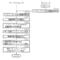
- FIG. It is explanatory drawing which shows the image of a warning screen. It is a flowchart which shows the procedure of an extraction process. It is a flowchart which shows the display processing procedure of warning information.
- FIG. 10 is a schematic diagram illustrating an overview of a processing system according to an eighth embodiment.
- FIG. 20 is a block diagram illustrating a hardware group of a computer according to a ninth embodiment. It is explanatory drawing which shows the record layout of statistics DB which concerns on Embodiment 10.
- FIG. It is a flowchart which shows the display processing procedure of a statistics. It is a flowchart which shows the display processing procedure of a statistics. It is explanatory drawing which shows the display image of countermeasure information.
- FIG. 1 is a schematic diagram showing an outline of a processing system.
- the processing system includes a computer 1, a semiconductor processing device 20, an information processing device 2, and the like.
- the semiconductor processing apparatus 20 is an apparatus that performs processing on a semiconductor according to the control of the information processing apparatus 2.
- the semiconductor processing apparatus 20 is, for example, a film forming apparatus, a cleaning apparatus, an etching apparatus, or an exposure apparatus that forms an oxide film on a wafer.
- the semiconductor processing apparatus 20 is described as the film forming apparatus 20, but the present invention is not limited to this.
- the information processing apparatus 2 is, for example, a computer incorporated in the film forming apparatus 20, a personal computer externally attached to the film forming apparatus 20, or a PDA (Personal Digital Assistance).
- a description will be given assuming that the computer 2 is incorporated in the film forming apparatus 20 as an example of the information processing apparatus 2.
- a computer 1 connected to a plurality of computers 2 via a communication network N such as a LAN (Local Area Network) or the Internet is, for example, a server computer or a personal computer.
- LAN Local Area Network
- the Internet is, for example, a server computer or a personal computer.
- the server computer 1 transmits / receives information to / from each computer 2A, 2B, 2C (hereinafter represented by the computer 2 in some cases) connected via the communication network N by using HTTP (HyperText Transfer Protocol) or the like. To do.
- HTTP HyperText Transfer Protocol
- the computers 2A, 2B, and 2C are incorporated in film forming apparatuses 20A, 20B, and 20C (hereinafter, represented by 20 in some cases). For example, when an abnormality occurs in the film forming apparatus 20A, the computer 2A displays abnormality information regarding the abnormality that has occurred. The user inputs countermeasure information when dealing with the abnormality to the computer 2A. The computer 2A transmits the input countermeasure information to the server computer 1 together with abnormality specifying information (hereinafter referred to as an abnormality ID) for specifying the abnormality.
- an abnormality ID abnormality specifying information
- each semiconductor processing apparatus 20 may be a different type of apparatus.
- the film forming apparatus 20A, the etching apparatus 20B, and the exposure apparatus 20C may be connected.
- each semiconductor processing apparatus 20 is installed in one factory or facility such as a laboratory will be described, but the present invention is not limited to this.
- the film forming apparatuses 20A and 20B may be installed in one factory and the film forming apparatus 20C may be installed in another factory and connected via the communication network N.
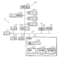
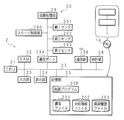
- FIG. 2 is a block diagram showing a hardware group of the computer 2.
- the computer 2 includes a central processing unit (CPU) 21 as a control unit, a random access memory (RAM) 22, an input unit 23, a display unit 24, a storage unit 25, a communication unit 26, a communication port 294, a clock unit 28, and the like.
- the film forming apparatus 20 is connected to the computer 2 via the communication port 294.
- the CPU 21 is connected to each part of the hardware via the bus 27.
- the CPU 21 controls each part of the hardware and executes various software functions according to the control program 25P stored in the storage unit 25.
- the input unit 23 is an input device such as a mouse, a keyboard, a control button for controlling the film forming apparatus 20, a switch, or a touch panel.
- the input unit 23 outputs the received operation information to the CPU 21.
- the display unit 24 is a liquid crystal display, an organic EL (electroluminescence) display, or the like, and displays various types of information including abnormality information according to instructions from the CPU 21.
- the RAM 22 is, for example, SRAM (Static RAM), DRAM (Dynamic RAM), flash memory, or the like.
- the RAM 22 also functions as a storage unit, and temporarily stores various data generated when the CPU 21 executes various programs.
- the communication unit 26 is a wireless or wired LAN card.
- the communication unit 26 transmits / receives information to / from the server computer 1 via the communication network N.
- the clock unit 28 outputs date / time information to the CPU 21.
- the storage unit 25 is, for example, a hard disk or a large-capacity flash memory.
- the storage unit 25 stores an abnormality file 251, a countermeasure information file 252, and an abnormality history file 253.
- an example in which the abnormal file 251, the countermeasure information file 252, and the abnormal history file 253 are stored in the storage unit 25 will be described.
- the present invention is not limited to this. Absent.
- the abnormal file 251, the countermeasure information file 252, or the abnormal history file 253 is stored in the server computer 1 or a database (not shown) server (not shown), and the CPU 21 reads or stores data as necessary. You may do it.
- the communication port 294 is, for example, a USB port (Universal Serial Bus) or a communication port based on the RS232C standard.
- the communication port 294 transmits and receives information between the computer 2 and the film forming apparatus 20.
- the film forming apparatus 20 includes a film forming processing unit 29, a stage control unit 290, a first sensor 291, a second sensor 292, a third sensor 293, and the like.
- the film formation processing unit 29 forms an oxide film or the like on the wafer, for example.
- the stage controller 290 controls the movement of the stage on which the wafer is placed.
- the first sensor 291 to the third sensor 293 are sensors that detect the temperature, gas flow rate, stage position, and the like of the film forming apparatus 20. In the present embodiment, only a part of the functions of the film forming apparatus 20 has been described for ease of explanation, but other configurations may be included.
- FIG. 3 is an explanatory diagram showing a record layout of the abnormal file 251.
- the abnormality file 251 stores abnormality information related to an abnormality that has occurred in the film forming apparatus 20 in association with the abnormality ID.
- the abnormality file 251 includes an abnormality ID field and an abnormality information field.
- the abnormality ID field a unique ID for specifying an abnormality occurring in the film forming apparatus 20 is stored.
- abnormality information field abnormality information is stored in association with the abnormality ID.
- the abnormality ID “1001” stores abnormality information indicating that the first sensor 291 that detects the movement of the stage in the X-axis direction has not reacted.
- the abnormality is specified by the abnormality ID, but the present invention is not limited to this.
- the abnormality ID “1001” may be replaced with “stage” and “first sensor”.
- the abnormality ID “1002” may be replaced with “stage” and “second sensor”.
- the abnormality ID “2003” may be replaced with “gas supply unit” and “third sensor”.
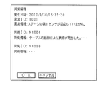
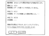
- FIG. 4 is an explanatory diagram showing a display image of abnormality information.
- the film forming apparatus 20 outputs an abnormality ID to the CPU 21 via the communication port 294.
- the CPU 21 reads the abnormality information corresponding to the abnormality ID from the abnormality file 251 and displays it on the display unit 24. Further, the CPU 21 acquires date / time information output from the clock unit 28 when the abnormality ID is output.
- the CPU 21 displays the acquired date / time information on the display unit 24 as the occurrence date / time.
- the abnormality ID, abnormality information, and occurrence date and time are displayed. “The first sensor on the stage is not responding” is displayed as the abnormality information of the abnormality ID “1001”. Note that image data and template data for screen display are stored in the storage unit 25.
- the CPU 21 displays a countermeasure information display button 241 for displaying the countermeasure information on the display unit 24. Processing when the handling information display button 241 is operated will be described later.
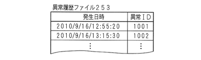
- FIG. 5 is an explanatory diagram showing a record layout of the abnormality history file 253.
- the abnormality history file 253 stores a history of abnormality that has occurred.
- the abnormality history file 253 includes an occurrence date / time field and an abnormality ID field.
- the occurrence date / time field stores the occurrence date / time when an abnormality occurred.
- an abnormality ID is stored in association with the occurrence date and time.
- the CPU 21 stores the abnormality ID and the occurrence date / time in the abnormality history file 253.
- FIG. 6 is an explanatory diagram showing an image of the selection screen.
- the user inputs, as know-how, countermeasure information when dealing with an abnormality
- the user inputs a selection screen display command for selecting an abnormality history that occurred in the past from the input unit 23.
- the CPU 21 reads the occurrence date and time and the abnormality ID from the abnormality history file 253 and displays them on the display unit 24.
- the CPU 21 displays an occurrence date and time, an abnormality ID, and a check box for selection on the selection screen.
- the user selects one occurrence date and time and an abnormality ID for inputting the countermeasure information from the input unit 23, and operates the “OK” button.
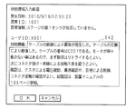
- FIG. 7 is an explanatory diagram showing an image of the countermeasure information input screen.
- the CPU 21 receives the occurrence date and time and the abnormality ID selected on the selection screen, and reads the abnormality information corresponding to the abnormality ID from the abnormality file 251. As shown in FIG. 7, the CPU 21 displays the occurrence date / time, the abnormality ID, and the abnormality information on the countermeasure information input screen. Further, the CPU 21 displays a screen that prompts input of a user ID. Further, the CPU 21 displays a countermeasure information input box 242 for inputting countermeasure information.
- the user ID is identification information for specifying the user who inputs the handling information.
- the CPU 21 receives a user ID input from the input unit 23. Instead of the user ID, information that can identify an individual such as a name may be input.
- the user inputs countermeasure information from the input unit 23 into the countermeasure information input box 242.
- the handling information the handling information when the user copes with the abnormality is input as a text sentence.
- the input of the handling information is not limited to a text sentence.
- an application file such as an image file, an audio file, or a PDF (Portable Document Format, registered trademark) file may be input.
- the OK button is input from the input unit 23, the CPU 21 receives the input user ID and handling information.
- the CPU 21 stores the received handling information and user ID in the handling information file 252 in association with the occurrence date and time and the abnormality ID.
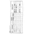
- FIG. 8 is an explanatory diagram showing a record layout of the countermeasure information file 252.
- the countermeasure information file 252 includes an occurrence date / time field, an abnormality ID field, a countermeasure ID field, a countermeasure information field, a user ID field, and the like.
- the countermeasure information field the countermeasure information input in the countermeasure information input box 242 is stored in association with the occurrence date and time and the abnormality ID.
- Unique identification information for specifying the countermeasure information is stored in the countermeasure ID field.
- the user ID field the user ID of the user who has input the handling information on the handling information input screen is stored in association with the handling information.
- the CPU 21 transmits information including the countermeasure information and the abnormality ID stored in the countermeasure information file 252 to the server computer 1 via the communication unit 26 at an appropriate timing.
- the example in which the countermeasure information file 252 is provided in the storage unit 25 has been described.
- the present invention is not limited to this. Instead of storing in the storage unit 25, it may be stored temporarily in the RAM 22 and the stored countermeasure information and abnormality ID may be transmitted to the server computer 1.
- the file and DB data layouts described in this embodiment are merely examples, and other forms may be used as long as the relationship between the data is maintained.
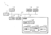
- FIG. 9 is an explanatory diagram showing a hardware group of the server computer 1.
- the server computer 1 includes a CPU 11 as a control unit, a RAM 12, an input unit 13, a display unit 14, a communication unit 16, a clock unit 18, a storage unit 15, and the like.
- the CPU 11 is connected to each part of the hardware via the bus 17.
- the CPU 11 controls each hardware and executes a software function according to a control program 15P stored in the storage unit 15.
- the clock unit 18 outputs the date and time to the CPU 11.
- the communication unit 16 is a gateway or the like that functions as a firewall, and transmits / receives information to / from the computer 2 or another server computer (not shown) by HTTP or the like.
- the input unit 13 is an input device such as a mouse, a keyboard, or a touch panel.
- the input unit 13 outputs the received operation information to the CPU 11.
- the display unit 14 is a liquid crystal display, an organic EL display, or the like, and displays various types of information including abnormality information according to instructions from the CPU 11.
- the RAM 12 is, for example, SRAM, DRAM, flash memory or the like.
- the RAM 12 also functions as a storage unit, and temporarily stores various data generated when the CPU 11 executes various programs.
- the storage unit 15 is, for example, a hard disk or a large capacity memory. In addition to the control program 15P described above, the storage unit 15 stores a device DB 151, a handling information DB 152, and the like.
- the device DB 151 or the handling information DB 152 may be stored in a DB server (not shown), and the CPU 11 may read or store data using SQL (Structured Query Query Language).
- SQL Structured Query Query Language
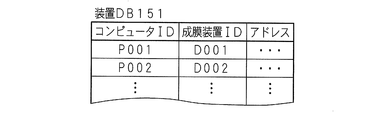
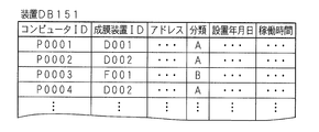
- FIG. 10 is an explanatory diagram showing a record layout of the device DB 151.
- the apparatus DB 151 includes a computer ID field, a film forming apparatus ID field, an address field, and the like.
- the computer ID field unique identification information for specifying the computer 2 is stored.
- the film forming apparatus ID field unique identification information for specifying the film forming apparatus 20 is stored in association with the computer ID.
- the address field the address of the computer 2 such as an IP (Internet Protocol) address or a MAC (Media Access Control) address is stored in association with the computer ID.
- IP Internet Protocol
- MAC Media Access Control
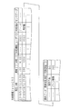
- FIG. 11 is an explanatory diagram showing a record layout of the countermeasure information DB 152.
- the countermeasure information DB 152 includes an occurrence date / time field, an abnormality ID field, a countermeasure ID field, a countermeasure information field, a user ID field, a computer ID field, and the like.
- the CPU 11 stores the information in the countermeasure information DB 152.
- the countermeasure information regarding the abnormality ID “1001” is transmitted from the computer 2A having the computer ID “P001” and the computer 2B having the computer ID “P002”, respectively.
- the countermeasure information is collected from the computer 2 of each film forming apparatus 20 for each abnormality ID.
- FIG. 12 is an explanatory diagram showing a display image of countermeasure information.
- the user desires to acquire the countermeasure information already collected when an abnormality occurs, the user inputs the countermeasure information display button 241 shown in FIG.
- the CPU 21 receives an operation of the countermeasure information display button 241 from the input unit 23, the CPU 21 transmits a computer ID, an abnormality ID, and a countermeasure information acquisition request to the server computer 1 via the communication unit 26.
- the CPU 11 of the server computer 1 receives a computer ID, abnormality ID, and handling information acquisition request via the communication unit 16.
- the CPU 11 extracts the countermeasure ID and the countermeasure information corresponding to the abnormality ID from the countermeasure information DB 152.
- the CPU 11 reads an address corresponding to the computer ID from the device DB 151.
- the CPU 11 transmits the read countermeasure ID and the countermeasure information to the computer 2 associated with the read address.
- the CPU 21 of the computer 2 displays the received countermeasure ID and countermeasure information on the display unit 24.
- the countermeasure information for the countermeasure IDs “N1001” and “N1008” is displayed as the countermeasure information for the abnormality ID “1001”.
- FIG. 13 is a flowchart showing a procedure of handling information reception processing.
- the CPU 21 receives an abnormality ID from the film forming apparatus 20 in which an abnormality has occurred via the communication port 294 (step S131).
- the CPU 21 reads out abnormality information corresponding to the abnormality ID from the abnormality file 251 (step S132).
- the CPU 21 displays the abnormality ID, the abnormality information, the occurrence date / time of the abnormality based on the date / time information acquired from the clock unit 28, and the countermeasure information display button 133 on the display unit 24 on the abnormality information display screen (step S133).
- the CPU 21 stores the occurrence date and time and the abnormality ID in association with each other in the abnormality history file 253 (step S134).
- the CPU 21 reads out the occurrence date and time and the abnormality ID stored in the abnormality history file 253 and displays them on the display unit 24.
- the CPU 21 accepts the selection of one occurrence date / time and an abnormality ID for which it is desired to input countermeasure information through the input unit 23 (step S135).
- the CPU 21 reads out from the abnormality file 251 the abnormality information corresponding to the date and time of occurrence of the selection and the abnormality ID.
- the CPU 21 displays the occurrence date, abnormality ID, and abnormality information on the countermeasure information input screen (step S136).
- the CPU 21 further displays a countermeasure information input box 242 on the display unit 24.
- the CPU 21 receives the user ID and the handling information from the input unit 23 (step S137).
- the CPU 21 generates a countermeasure ID corresponding to the input countermeasure information (step S138).
- the CPU 21 stores the occurrence date and time, the abnormality ID, the countermeasure ID, the countermeasure information, and the user ID in the countermeasure information file 252 (step S139). Thereafter, the CPU 21 transmits (outputs) the occurrence date and time, the abnormality ID, the countermeasure ID, the countermeasure information, the user ID, and the computer ID to the server computer 1 via the communication unit 26 (step S1310).
- FIG. 14 is a flowchart showing a procedure for handling information display processing.
- the CPU 11 receives the occurrence date and time, the abnormality ID, the countermeasure ID, the countermeasure information, the user ID, and the computer ID transmitted from the computer 2 (step S141).
- the CPU 11 stores the received occurrence date / time, abnormality ID, countermeasure ID, countermeasure information, user ID, and computer ID in the countermeasure information DB 152 (step S142).
- the CPU 21 of the computer 2 receives an input of the countermeasure information display button 241 from the input unit 23.
- the CPU 21 receives an input of the countermeasure information display button 241, it transmits a computer ID, an abnormality ID, and a countermeasure information acquisition request to the server computer 1 (step S143).
- the CPU 11 of the server computer 1 receives an acquisition request for a computer ID, an abnormality ID, and countermeasure information.
- the CPU 11 reads out the countermeasure ID and the countermeasure information corresponding to the received abnormality ID from the countermeasure information DB 152 (step S144).
- the CPU 11 reads an address corresponding to the computer ID received from the device DB 151 (step S145).
- the CPU 11 transmits the read countermeasure ID and the countermeasure information to the computer 2 addressed to the read address (step S146).
- the CPU 21 of the computer 2 receives (acquires) the countermeasure ID and the countermeasure information (step S147).
- the CPU 21 displays the received countermeasure ID and countermeasure information on the display unit 24 together with the abnormality ID, the abnormality information, and the date and time of occurrence (step S148).
- the handling information input by each computer 2 can be shared, and it becomes possible to deal with an abnormality efficiently.
- the server computer 1 transmits corresponding countermeasure information.
- the CPU 11 of the server computer 1 may transmit the handling information corresponding to the abnormality ID to each computer 2 periodically, for example, every 3 hours.
- Each computer 2 may store countermeasure information corresponding to the received abnormality ID in the storage unit 25.
- the CPU 21 of the computer 2 may read out the handling information corresponding to the abnormality ID from the storage unit 25 and display it.
- Embodiment 2 The second embodiment relates to a mode in which handling information is transmitted and received between the computers 2 without using the server computer 1.
- FIG. 15 is a schematic diagram showing an outline of a processing system according to the second embodiment.
- the computers 2A, 2B, 2C,... are connected via a communication network N on a peer-to-peer basis.
- the countermeasure information is input by the computer 2A and the countermeasure information file 252 is updated, the updated countermeasure information is also transmitted to the other computers 2B and 2C.
- the countermeasure information is displayed with reference to the countermeasure information file 252 of its own.
- FIG. 16 is a flowchart showing a procedure for handling information display processing according to the second embodiment.
- the CPU 21 receives the input of the user ID and the handling information from the input unit 23 (step S161).
- the CPU 11 generates a countermeasure ID for identifying the countermeasure information (step S162).
- the CPU 11 stores the occurrence date / time, the abnormality ID, the countermeasure ID, the countermeasure information, the user ID, and the computer ID in the countermeasure information file 252 (step S163).
- the CPU 21 transmits the newly stored occurrence date / time, abnormality ID, countermeasure ID, countermeasure information, user ID, and computer ID to the other computer 2 (step S164).
- each computer 2 transmits the updated data to another computer 2 each time the countermeasure information file 252 is updated.
- the CPU 21 of the computer 2 receives the occurrence date / time, the abnormality ID, the countermeasure ID, the countermeasure information, the user ID, and the computer ID transmitted from the other computer 2 (step S165).
- the CPU 21 stores the received information in the countermeasure information file 252 (step S166).
- the CPU21 receives the input of the countermeasure information display button 241 shown in FIG. 4 from the input part 23 (step S167).
- the CPU 21 reads out the countermeasure ID and the countermeasure information corresponding to the abnormality ID from the countermeasure information file 252 (step S168).
- the CPU 21 displays the read countermeasure ID and countermeasure information on the display unit 24 (step S169). This makes it possible to share the handling information between the computers 2 with a simple configuration.
- the second embodiment is as described above, and the other parts are the same as those of the first embodiment. Therefore, the corresponding parts are denoted by the same reference numerals, and detailed description thereof is omitted.
- Embodiment 3 relates to a form for collecting items to be dealt with at the time of abnormality and the cause of occurrence of the abnormality.
- FIG. 17 is an explanatory diagram showing a record layout of the abnormal file 251 according to the third embodiment.
- the abnormality file 251 includes an abnormality ID field, an abnormality information field, a countermeasure item field, an abnormality occurrence cause field, and the like.
- the countermeasure item field a plurality of candidate countermeasure items are stored when an abnormality occurs in association with the abnormality ID.
- three countermeasure items are stored as an example.
- the countermeasure items are, for example, “retry”, “process continuation”, and “restart”.
- Each candidate handling item stores a description regarding a specific handling item in association with the abnormality ID.
- the abnormality occurrence cause field a plurality of abnormality occurrence causes that cause an abnormality are stored in association with the abnormality ID. For example, “design failure” or “adjustment failure”.
- FIG. 18 is an explanatory diagram showing an image of the abnormality information display screen.
- the abnormality ID and abnormality information are displayed, and a plurality of candidate countermeasure items are displayed.
- the CPU 21 refers to the abnormal file 251 and displays on the display unit 24 candidates for countermeasure items corresponding to the abnormality ID and explanations regarding the respective countermeasure items. For example, if the action item “Retry” is “Retry” as an explanation, the stage will move up again. Is displayed.
- the user inputs one countermeasure item from the plurality of countermeasure items from the input unit 23.
- the CPU 21 accepts a countermeasure item input from the input unit 23.
- the CPU 21 outputs a signal corresponding to the handling item to the film forming apparatus 20.
- the film forming apparatus 20 controls the film forming processing unit 29 or the stage control unit 290 according to the signal corresponding to the handling item.
- the CPU 21 is input from the input unit 23 from the time of occurrence of the abnormality until the output of the abnormality ID is stopped, from the time of occurrence of the abnormality to the time when the abnormality is resolved, or after a predetermined time elapses from the time of occurrence of the abnormality.
- the operation data is stored in the storage unit 25 in association with the occurrence date and abnormality ID. Note that other operation data input from the film forming apparatus 20 may also be stored in the storage unit 25.
- operation data input from the input unit 23 is stored in the storage unit 25 from the occurrence of an abnormality until a predetermined time (for example, 5 minutes) has elapsed.
- the CPU 21 stores the setting data before the occurrence of the abnormality of the first sensor 291 to the third sensor 293 and the data at the time of occurrence of the abnormality (hereinafter referred to as sensor data depending on the case) in the storage unit 25 in association with the occurrence date and time and the abnormality ID.
- FIG. 19 is an explanatory diagram showing a record layout of the countermeasure information file 252. Furthermore, a countermeasure item field, a sensor data field, an operation data field, an abnormality occurrence cause field, and a replacement part ID field are provided. In the countermeasure item field, a countermeasure item selected by the user on the abnormality information display screen shown in FIG. 18 is stored. When a countermeasure item is input from the input unit 23, the CPU 21 stores the countermeasure item in the countermeasure information file 252 in association with the occurrence date and time and the abnormality ID.
- the sensor data field, operation data field, abnormality cause field, and replacement part ID field will be described later.
- FIG. 20 is an explanatory diagram showing an image of the countermeasure information input screen.
- data regarding replacement parts and the cause of occurrence of an abnormality can be input.
- the user inputs a replacement part ID from the input unit 23 when the part needs to be replaced when the abnormality is dealt with.
- the CPU 21 receives a replacement part ID input via the input unit 23.
- a list of replacement part names may be displayed and one replacement part may be selected.
- the CPU 21 stores the replacement part ID in the replacement part ID field of the handling information file 252 in association with the occurrence date and time and the abnormality ID.
- the CPU 21 reads out a plurality of cause of anomalies corresponding to the anomaly ID from the anomaly file 251.
- the CPU 21 displays a plurality of abnormality cause candidates on the display unit 24. As shown in FIG. 20, a plurality of candidates for the cause of abnormality are displayed together with check boxes.
- the user selects one cause of the abnormality from the displayed causes of the abnormality. In the present embodiment, an example of selecting one cause of occurrence of an abnormality is given for ease of explanation, but a plurality of causes may be selected.
- the CPU 21 receives the cause of the abnormality selected from the input unit 23.
- the CPU 21 stores the cause of the abnormality received in association with the occurrence date / time and the abnormality ID in the abnormality cause field of the handling information file 252.
- the CPU 21 displays information asking whether or not to store the operation data from the input unit 23 stored in association with the occurrence date and time and the abnormality ID in the handling information file 252 when the abnormality occurs on the display unit 24. To do. As shown in FIG. 20, when the operation data is stored, the check box of “Attach operation data” is clicked.
- the CPU 21 receives an operation data storage command from the input unit 23, the CPU 21 stores the operation data stored in the storage unit 25 in the operation data field of the handling information file 252 in association with the occurrence date and time and the abnormality ID.
- the CPU 21 stores the setting data of the first sensor 291 to the third sensor 293 and the data at the time of abnormality stored in the countermeasure information file 252 on the display unit 24 in association with the occurrence date and time and the abnormality ID when the abnormality occurs. Displays information that asks. As shown in FIG. 20, when storing the setting data of the first sensor 291 and the data at the time of abnormality, the user clicks the check box of “Attach first sensor data”. When the CPU 21 receives the setting data of the first sensor 291 to the third sensor 293 and the storage command of the data at the time of abnormality, the CPU 21 associates these data with the occurrence date and time and the abnormality ID, and the sensor data field of the countermeasure information file 252 To remember.
- the server computer stores the occurrence date / time, abnormality ID, countermeasure ID, countermeasure information, user ID, countermeasure item, sensor data, operation data, cause of abnormality, replacement part ID, and computer ID. Send to 1.
- FIG. 21 is an explanatory diagram showing a record layout of the countermeasure information DB 152 according to the second embodiment. Furthermore, a countermeasure item field, a sensor data field, an operation data field, an abnormality occurrence cause field, and a replacement part ID field are provided.
- the CPU 11 of the server computer 1 stores the date and time of occurrence, abnormality ID, countermeasure ID, countermeasure information, user ID, countermeasure item, sensor data, operation data, cause of abnormality, replacement part ID, and computer ID transmitted from the computer 2. Thereby, various know-how is accumulated from each computer 2.
- the CPU 21 receives an abnormality ID from the film forming apparatus 20 in which an abnormality has occurred via the communication port 294 (step S221).
- the CPU 21 reads abnormality information corresponding to the abnormality ID from the abnormality file 251 (step S222).
- the CPU 21 reads a plurality of countermeasure items corresponding to the abnormality ID from the abnormality file 251 (step S223).
- the CPU 21 displays the abnormality ID, the abnormality information, the occurrence date / time of the abnormality based on the date / time information acquired from the clock unit 28, a plurality of countermeasure items and the countermeasure information display button 133 on the abnormality information display screen (step S224). .
- the CPU 21 stores the operation data input from the operation mechanism and control mechanism (not shown) of the input unit 23 or the film forming apparatus 20 in the storage unit 25 in association with the date and time information output from the clock unit 28 (step S225).
- the CPU 21 associates the setting data stored in advance in the storage unit 25 of the first sensor 291 to the third sensor 293 with the abnormal data output from the first sensor 291 to the third sensor 293 in the event of an abnormality. 25 (step S226).
- the CPU 21 receives a countermeasure item selected from a plurality of countermeasure items via the input unit 23 (step S227).
- the CPU 21 stores the occurrence date and time, the abnormality ID, the handling item, the operation data, the setting data related to the first sensor 291 to the third sensor 293, and the data at the time of abnormality in the abnormality history file 253 in association with each other (step S228).
- the CPU 21 determines whether or not a handling information display request has been received through the handling information display button 241 (step S229). When the CPU 21 determines that a request for displaying the handling information has been received (YES in step S229), the CPU 21 performs the processing described in FIG. 14 and displays the handling information on the display unit 24 (step S231). If the CPU 21 has not received a display request for handling information (NO in step S229), the process proceeds to step S232.
- the CPU 21 In order for the user to input the handling information, the CPU 21 reads out the occurrence date and time and the abnormality ID stored in the abnormality history file 253 and displays them on the display unit 24.
- the CPU 21 receives selection of one occurrence date / time and an abnormality ID for which the handling information is desired to be input through the input unit 23 (step S232).
- the CPU 21 reads out from the abnormality file 251 the abnormality information corresponding to the date and time of occurrence of the selection and the abnormality ID.
- the CPU 21 displays the occurrence date and time, the abnormality ID, and the abnormality information on the countermeasure information input screen (step S233).
- the CPU 21 further displays a countermeasure information input box 242 on the display unit 24.
- the CPU 21 receives the user ID and the handling information from the input unit 23 (step S234).
- the CPU 21 generates a countermeasure ID corresponding to the input countermeasure information (step S235).
- the CPU 21 reads a plurality of cause of anomalies corresponding to the anomaly ID from the anomaly file 251 (step S236).
- the CPU 21 displays a plurality of abnormality occurrence causes on the display unit 24 (step S237).
- the CPU 21 accepts selection of the cause of the abnormality through the input unit 23 (step S238).
- the CPU 21 accepts the input of the replacement part ID (step S239). If there is no replacement part, there is no need to input the replacement part ID.
- the CPU 21 receives information on whether or not to attach operation data via the input unit 23 (step S2310).
- the CPU 21 receives information on whether to attach the data of the first sensor 291 to the third sensor 293 via the input unit 23 (step S2311).
- the CPU 21 stores the occurrence date / time, abnormality ID, countermeasure ID, countermeasure information, countermeasure item, user ID, cause of abnormality, replacement part ID, operation data, setting data, and abnormality data in the countermeasure information file 252 (step) S2312). Note that if the information to which the operation data is attached is not input in step S2310, the operation data may not be stored in the countermeasure information file 252. In step S2311, if the information that the data of the first sensor 291 to the third sensor 293 is attached is not received, the setting data and the data at the time of abnormality need not be stored in the handling information file 252.
- the CPU 21 via the communication unit 26 generates the occurrence date / time, abnormality ID, countermeasure ID, countermeasure information, countermeasure item, user ID, cause of abnormality, replacement part ID, operation data, setting data, data at the time of abnormality, and computer ID. Is transmitted to the server computer 1 (step S2313).
- the CPU 11 of the server computer 1 receives the occurrence date and time, the abnormality ID, the countermeasure ID, the countermeasure information, the user ID, the cause of the abnormality, the replacement part ID, the operation data, the setting data, the data at the time of abnormality, and the computer ID via the communication unit 16. Receive.
- the CPU 11 stores the received occurrence date / time, abnormality ID, countermeasure ID, countermeasure information, countermeasure item, user ID, cause of abnormality, replacement part ID, operation data, setting data, data at the time of abnormality, and computer ID in the countermeasure information DB 152. (Step S2314). Thereby, in addition to the handling information input by the input unit 23, various information can be accumulated as know-how.
- the third embodiment is as described above, and the other parts are the same as in the first and second embodiments. Therefore, the corresponding parts are denoted by the same reference numerals, and detailed description thereof is omitted.
- Embodiment 4 relates to a form for displaying countermeasure items and statistics of the cause of abnormality when displaying countermeasure information.
- FIG. 24 is a block diagram illustrating a hardware group of the server computer 1 according to the fourth embodiment.
- the storage unit 15 is newly provided with a statistics DB 153.
- FIG. 25 is an explanatory diagram showing a record layout of the statistics DB 153.
- the statistics DB 153 includes an abnormality ID field, a countermeasure item field, an abnormality occurrence cause field, a number field, and a ratio field.
- a plurality of action items are stored in association with the abnormality ID.
- the number field corresponding to the countermeasure item the number of selected countermeasure items is stored in association with the countermeasure item.
- the CPU 11 of the server computer 1 refers to the countermeasure information file 252 and counts the number of countermeasure items corresponding to the abnormality ID.
- the CPU 11 stores the counted value as the number of cases in the statistics DB 153 for each handling item.
- the CPU 11 calculates the ratio of each handling item by dividing the number of handling items by the number of all handling items and multiplying by 100.
- the CPU 11 stores the calculated ratio in the statistics DB 153 in association with the abnormality ID and the countermeasure item.
- the abnormality occurrence cause field a plurality of abnormality occurrence causes are stored in association with the abnormality ID. In the number of cases corresponding to the cause of abnormality occurrence, the number of selected cause of abnormality occurrence is stored in association with the cause of abnormality occurrence.
- the CPU 11 of the server computer 1 refers to the countermeasure information file 252 and counts the number of causes of the abnormality corresponding to the abnormality ID.
- the CPU 11 stores the counted value as the number of cases in the statistical DB 153 for each cause of abnormality.
- the CPU 11 calculates the ratio of each abnormality occurrence cause by dividing the number of occurrences of each abnormality occurrence by the number of all abnormality occurrence causes and multiplying by 100.
- the CPU 11 stores the calculated ratio in the statistics DB 153 in association with the abnormality ID and the cause of the abnormality.
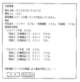
- FIG. 26 is an explanatory diagram showing a display image of countermeasure information.
- the statistics of the countermeasure item and the statistics of the cause of the abnormality are displayed.
- the CPU 11 of the server computer 1 receives the request for acquiring the abnormality ID and the countermeasure information, the CPU 11 refers to the statistical DB 153 to determine the countermeasure items corresponding to the abnormality ID, the number and ratio of the countermeasure items, the cause of the abnormality, and the cause of the abnormality. Read the number and ratio of such cases.
- the CPU 11 transmits the read countermeasure item, the number and ratio of the countermeasure item, the cause of the abnormality, and the number and ratio of the cause of the abnormality to the computer 2. As shown in FIG.
- the CPU 21 of the computer 2 displays the number and ratio of each countermeasure item as well as the number and ratio of the cause of the abnormality as shown in FIG.
- the OK button is input through the input unit 23
- the CPU 21 returns to the abnormality information display screen shown in FIG.
- an appropriate countermeasure item can be selected based on past countermeasure item statistics.
- an example is shown in which both the number of cases and the ratio are displayed as statistics, but this is an example and the present invention is not limited to this. Either the number of cases or the ratio may be used, and in the case of statistics, a graph or the like may be displayed.
- the display unit 24 may display the replacement part ID, operation data, setting data of the first sensor 291 to the third sensor 293, and data at the time of abnormality.
- the CPU 11 of the server computer 1 refers to the countermeasure information DB 152 and reads the countermeasure ID corresponding to the abnormality ID, the replacement part ID, the operation data, the setting data of the first sensor 291 to the third sensor 293, and the data at the time of abnormality.
- the CPU 11 transmits the countermeasure ID, the replacement part ID, the operation data, the setting data of the first sensor 291 to the third sensor 293, and the data at the time of abnormality to the computer 2.
- the CPU 21 of the computer 2 displays the received countermeasure ID, replacement part ID, operation data, setting data of the first sensor 291 to the third sensor 293, and data at the time of abnormality on the display unit 24.
- FIG. 27 and FIG. 28 are flowcharts showing the statistical display processing.
- the CPU 11 receives the abnormality ID, the countermeasure item, and the cause of the abnormality transmitted from the computer 2 (step S271).
- the CPU 11 refers to the handling information DB 152, counts the handling items and the cause of occurrence of the abnormality, and stores the counted number in the statistics DB 153 (step S272).
- the counting process may be performed periodically (for example, every hour) or whenever the abnormality ID, the countermeasure item, and the cause of the abnormality are transmitted from the computer 2.
- the CPU 11 calculates the ratio of the countermeasure item and the cause of occurrence of the abnormality based on the counted number, and stores the calculated ratio in the statistics DB 153 (step S273).
- the CPU 21 of the computer 2 receives an input of the countermeasure information display button 241 from the input unit 23.
- the CPU 21 receives an input of the countermeasure information display button 241, it transmits a computer ID, an abnormality ID, and a countermeasure information acquisition request to the server computer 1 (step S274).
- the CPU 11 of the server computer 1 receives the acquisition request for the computer ID, the abnormality ID, the countermeasure information, the replacement part ID, the operation data, the setting data of the first sensor 291 to the third sensor 293, and the data at the time of abnormality.
- the CPU 11 reads out the countermeasure ID, the countermeasure information, the replacement part ID, the operation data, the setting data of the first sensor 291 to the third sensor 293, and the data at the time of abnormality from the countermeasure information DB 152 corresponding to the received abnormality ID (step S275). ).
- the CPU 11 reads an address corresponding to the computer ID received from the device DB 151 (step S276).
- the CPU 11 transmits the read countermeasure ID, countermeasure information, replacement part ID, operation data, setting data of the first sensor 291 to the third sensor 293, and data at the time of abnormality to the computer 2 addressed to the read address (step) S277).
- the CPU 11 reads the number and ratio of the handling items corresponding to the abnormality ID and the number and ratio of the cause of the abnormality from the statistics DB 153 and transmits them to the computer 2 (step S278).
- the CPU 21 of the computer 2 receives the countermeasure ID, the countermeasure information, the replacement part ID, the operation data, the setting data of the first sensor 291 to the third sensor 293, and the data at the time of abnormality (step S279).
- the CPU 21 displays the received countermeasure ID, countermeasure information, replacement part ID, operation data, the setting data of the first sensor 291 to the third sensor 293 and the data at the time of abnormality together with the abnormality ID, abnormality information, and occurrence date and time. (Step S281).
- the CPU 21 receives the number and ratio of the handling items corresponding to the abnormality ID and the number and ratio of the cause of the abnormality (step S282).
- the CPU 21 displays the number and ratio of the handling items corresponding to the abnormality ID and the number and ratio of the cause of the abnormality on the display unit 24 (step S283).
- the statistics input in each computer 2 can be referred to, and an appropriate countermeasure item can be selected from a plurality of countermeasure items.
- the fourth embodiment is as described above, and the other parts are the same as those of the first to third embodiments. Therefore, the corresponding parts are denoted by the same reference numerals and the detailed description thereof is omitted.
- Embodiment 5 relates to a mode in which handling information is managed using information on a storage period.
- FIG. 29 is an explanatory diagram showing a handling information input screen. The user can input the storage period of the handling information through the input unit 23. Of course, the erasure date may be input instead of the retention period. In the present embodiment, an example of inputting a storage period will be described.
- the CPU 21 displays information for inputting the storage period from the storage unit 25. As shown in FIG. 29, the retention period is “permanent” for permanently storing the countermeasure information corresponding to the abnormality ID, “until the year, month, day,” until the predetermined date and time, and “until the predetermined month elapses” Month "is an example.
- the user selects “permanent” from the input unit 23. If the user thinks that erasing may be performed after a predetermined period, the user inputs the date and time for which the user wants to save or the number of months to save from the input unit 23.
- FIG. FIG. 30 is an explanatory diagram showing a record layout of the countermeasure information file 252 according to the fifth embodiment. A new retention period field is provided.
- the CPU 21 stores the storage period input through the input unit 23 in association with the occurrence date and time and the abnormality ID.
- the countermeasure information of the abnormality ID “1001” that occurred at 12:55:20 on September 16, 2010 is permanently stored.
- FIG. 31 is an explanatory diagram showing a record layout of the countermeasure information DB 152. A new retention period field is provided.
- the CPU 11 of the server computer 1 stores the retention period transmitted in association with the occurrence date / time and the abnormality ID in the handling information DB 152.
- the CPU 11 refers to the date / time information output from the clock unit 28 and deletes the record that has passed the storage period stored in the storage period field. Note that the operator may appropriately delete the less important handling information from the input unit 13 or another computer (not shown).
- FIG. 32 is a flowchart showing the procedure of the erasing process.
- the CPU 21 displays a countermeasure information input screen on the display unit 24 as shown in FIG. 29 (step S321).
- the CPU 21 receives the handling information and the storage period via the input unit 23 (step S322).
- the CPU 21 stores the occurrence date and time, the abnormality ID, the handling information, and the storage period in the handling information file 252 (step S323).
- the CPU 21 transmits the occurrence date and time, the abnormality ID, the countermeasure information, the storage period, and the computer ID to the server computer 1 (step S324).
- the CPU 11 of the server computer 1 receives the occurrence date / time, the abnormality ID, the countermeasure information, the storage period, and the computer ID (step S325).
- the CPU 11 stores the occurrence date / time, the abnormality ID, the handling information, the storage period, and the computer ID in the handling information DB 152 (step S326).
- the CPU 11 acquires date / time information from the clock unit 18 (step S327).
- the CPU 11 refers to the retention period field and date / time information in the countermeasure information DB 152, and determines whether there is countermeasure information that has passed the retention period (step S328). If the CPU 11 determines that it does not exist (NO in step S328), the process proceeds to step S327 and the process is repeated. Note that it is not necessary to process the handling information in which “permanent” is stored as the retention period.
- the CPU 11 determines that the countermeasure information that has passed the storage period is stored (YES in step S328), the CPU 11 deletes the countermeasure information that has passed the storage period (step S329). Specifically, the record including the handling information corresponding to the occurrence date and abnormality ID when the storage period of the handling information DB 152 has passed is deleted. As a result, only the handling information with higher importance and the data associated therewith are provided to the other computer 2, and the handling efficiency can be improved.
- the CPU 21 refers to the retention period field of the countermeasure information file and the date / time information output from the clock unit 28, and records related to the countermeasure information after the retention period has passed. Can be deleted.
- the fifth embodiment is as described above, and the other parts are the same as those of the first to fourth embodiments. Accordingly, the corresponding parts are denoted by the same reference numerals, and detailed description thereof is omitted.
- Embodiment 6 relates to a mode in which processing is executed based on statistics of countermeasure items.
- FIG. 33 is an explanatory diagram showing a record layout of the abnormal file 251 according to the sixth embodiment.
- a new execution instruction field is provided.
- an execution command for the film forming apparatus 20 is stored for each abnormality ID and countermeasure item.
- an execution command for moving the stage up again is stored in the stage control unit 290.
- the CPU 21 outputs an execution command to the film forming apparatus 20 via the communication port 294.
- the film forming apparatus 20 controls the stage control unit 290 to be raised according to the execution command.
- the countermeasure item “continue processing” is an instruction to ignore the abnormality information by the abnormality ID, for example, and continue the processing.
- the CPU 21 outputs a processing continuation command to the film forming apparatus 20 via the communication port 294.
- the film forming apparatus 20 continues the next process regardless of whether or not the first sensor 291 of the stage is reacting.
- the countermeasure item “restart” is a command to turn off the power of the computer 2 and the film forming apparatus 20 and turn it on again.
- the CPU 21 stops the power supply to the film forming apparatus 20 and then executes a restart process of the computer 2. After restarting, the CPU 21 starts supplying power to the film forming apparatus 20.
- the CPU 21 selects a handling item having the highest number or ratio based on the statistics described in the fourth embodiment, and reads out an execution command related to the handling item from the abnormal file 251.
- the CPU 21 performs processing for the film forming apparatus 20 based on the read execution instruction. For example, when the ratio of the countermeasure item “retry” is 95% or more, the process is executed based on the execution command related to “retry” when an abnormality occurs.
- FIG. 34 is a flowchart showing a procedure of execution processing.
- the CPU 21 transmits an acquisition request for a computer ID, an abnormality ID, and countermeasure information to the server computer 1 (step S341).
- the CPU 21 receives the number and ratio of each countermeasure item from the server computer 1 (step S342).
- the CPU 21 reads the threshold value for the number of cases and the threshold value for the ratio stored in advance from the storage unit 25 (step S343).
- the threshold for the number of cases is a value related to the total number of cases for all the handling items, and for example, “30” is stored.
- the threshold of the ratio is a value related to the ratio of the number of one handling item to the number of all the handling items, for example, 90% is stored.
- CPU 21 calculates the total value of the number of countermeasure items received in step S342.
- the CPU 21 determines whether or not the total number exceeds the threshold value of the number read in step S343 (step S344).
- the threshold value of the number read in step S343 the present invention is not limited to this.
- the number of handling items having the maximum number of cases may be compared with the threshold number of cases. If the CPU 21 determines that the total number of cases exceeds the threshold value of the number of cases (YES in step S344), the CPU 21 selects the ratio relating to the handling item having the highest ratio (step S345).
- the CPU 21 determines whether or not the ratio of the selected countermeasure item exceeds the threshold of the ratio read in step S343 (step S346). If the CPU 21 determines that the ratio of the selected countermeasure item exceeds the threshold of the ratio read in step S343 (YES in step S346), the CPU 21 proceeds to step S348. Note that the above-described threshold value can be changed by inputting an appropriate value from the input unit 23.
- step S344 if the CPU 21 determines that the threshold value is not exceeded (NO in step S344), if it is determined in step S346 that the ratio threshold value is not exceeded (NO in step S346), the process proceeds to step S347. As in step S283, the CPU 21 displays the number and ratio of the handling items on the display unit 24 (step S347). When YES is determined in the step S346, the CPU 21 reads out an execution command corresponding to the abnormality ID and the countermeasure item from the abnormality file 251 (step S348). The CPU 21 executes processing for the computer 2 or the film forming apparatus 20 in accordance with the read execution instruction (step S349). As a result, in the case of a highly reliable handling item, even if an abnormality occurs, it is possible to quickly return to the normal state by executing the corresponding process.
- the sixth embodiment is as described above, and the other parts are the same as those of the first to fifth embodiments. Therefore, the corresponding parts are denoted by the same reference numerals, and detailed description thereof is omitted.
- Embodiment 7 relates to a mode of providing countermeasure information to the computer 2 having the related film forming apparatus 20.
- FIG. 35 is an explanatory diagram showing a record layout of the device DB 151 according to the seventh embodiment. Further, a classification field, an installation date field, and an operation time field are provided. In the classification field, information for specifying the classification of the film forming apparatus 20 is stored. For example, a model number, a model name, and the like are stored. In this embodiment, for ease of explanation, it is assumed that classifications “A”, “B”, etc. are stored.
- the installation date field the installation date of the film forming apparatus 20 is stored together with the computer ID and the film forming apparatus ID.
- the operation time field the total value of the operation time of the film forming apparatus 20 is stored in association with the computer ID and the film forming apparatus ID.
- the computer 2 periodically transmits the operating time of the film forming apparatus 20 to the server computer 1.
- the CPU 11 of the server computer 1 stores the total operating time of the film forming apparatus 20 after installation in the operating time field.
- the CPU 11 extracts a computer 2 in which a similar abnormality may occur based on the classification and the total date of installation date or operation time.
- the CPU 11 extracts another computer 2 having the same classification as that of the one computer 2 and having an installation date that differs only by a predetermined period (for example, one month) stored in the storage unit 15.
- the CPU 11 extracts another computer 2 that has the same classification as the one computer 2 and whose operating time total value differs only by a predetermined time (for example, 24 hours).
- a predetermined time for example, 24 hours.
- FIG. 36 is an explanatory diagram showing an image of a warning screen.
- the CPU 11 of the server computer 1 reads out the abnormality ID and the countermeasure information corresponding to the abnormality ID from the countermeasure information DB 152.
- the CPU 11 describes the read countermeasure information and abnormality ID as an HTML (HyperText Markup Language) document.
- the CPU 11 further describes access information for browsing detailed information corresponding to the abnormality ID in the HTML document. For example, a URL (Uniform Resource Locator) partially including an abnormality ID is described.
- the CPU 11 refers to the extracted address of the computer 2 and transmits the warning information described as described above to the computer 2.
- the warning information shown in FIG. 36 is displayed on the display unit 24 of the computer 2.
- a display request for an abnormal ID and detailed information is transmitted to the server computer 1.
- the CPU 11 of the server computer 1 accepts an abnormality ID and detailed information display request.
- the CPU 11 refers to the countermeasure information DB 152 and transmits a countermeasure item corresponding to the abnormality ID, sensor data, operation data, cause of the abnormality, or replacement part information to the computer 2.
- FIG. 37 is a flowchart showing the procedure of the extraction process.
- the CPU 21 of the computer 2 transmits the computer ID and the operating time of the film forming apparatus 20 (step S371). For example, when the film forming apparatus 20 is powered off, the operating time may be obtained from the power on state to the off state. Note that when the film forming apparatus 20 has a function of calculating a total value of operation time from the installation time, the total value may be used.
- the CPU 11 of the server computer 1 receives the computer ID and the operating time (step S372).
- the CPU 11 refers to the operating time field of the device DB 151 and calculates the total operating time (step S373). Specifically, the CPU 11 adds the received operating time and the operating time stored in the operating time field.
- CPU11 memorize
- the CPU 11 refers to the device DB 151 and extracts computer IDs of the same classification (step S375).
- the CPU 11 reads the total value of the operating times of the extracted computer ID from the device DB 151.
- CPU11 reads the threshold value of operation time from the memory
- the CPU 11 extracts a computer ID whose difference between the total values of the operating times of the two computer IDs is within a threshold (step S377).
- the CPU 11 extracts an address corresponding to the extracted computer ID (step S378). This makes it possible to extract computer IDs that have the same classification and approximate operating time.
- FIG. 38 is a flowchart showing a warning information display processing procedure.
- the CPU 11 of the server computer 1 receives the abnormality ID and the countermeasure information from the one computer 2 (step S381).
- CPU11 extracts the address of the other computer 2 relevant to the one computer 2 by the process shown in FIG. 37 (step S382).
- CPU11 produces
- the CPU 11 refers to the address extracted in step S382 and transmits the abnormality ID, the countermeasure information, and the URL as warning information to another computer 2 (step S384).
- the CPU 21 of the other computer 2 receives the abnormality ID, the countermeasure information, and the URL (step S385).
- the CPU 21 displays the abnormality ID, the countermeasure information, and the URL as warning information on the display unit 24 (step S386).
- the CPU 21 transmits a display request for the computer ID, the abnormality ID, and the detailed information to the server computer 1 by using the user's URL operation as a trigger (step S387).
- the CPU 11 of the server computer 1 receives the computer ID, the abnormality ID, and the detailed information display request (step S388).
- the CPU 11 transmits the handling item corresponding to the abnormality ID, sensor data, operation data, the cause of the abnormality, and information on the replacement part to the other computer 2 (step S389).
- the countermeasure item and abnormality cause statistics may be transmitted together.
- the CPU 21 of the other computer 2 displays on the display unit 24 the countermeasure item corresponding to the abnormality ID, sensor data, operation data, cause of the abnormality, and replacement part information. Accordingly, even if no abnormality has occurred, it is possible to quickly know the abnormality that has occurred in the highly relevant film forming apparatus 20.
- Embodiment 8 relates to a mode in which information of a plurality of server computers 1 is shared.
- FIG. 39 is a schematic diagram showing an outline of a processing system according to the eighth embodiment.
- You may provide the server computer 3, the computer 4, and the film-forming apparatus 20 of the structure similar to the server computer 1, the computer 2, and the film-forming apparatus 20 which were described by embodiment mentioned above.
- the server computer 3 also includes a plurality of computers 4A, 4B, and 4C, and each of the computers 4A, 4B, and 4C is incorporated in each of the film forming apparatuses 40A, 40B, and 40C (hereinafter represented by 40 in some cases).
- the server computer 1 and the server computer 3 are connected to the general server computer 10 via a communication network N such as the Internet.
- a communication network N such as the Internet.
- a communication network N such as the Internet
- the stored contents of the handling information DB 152 described in the server computer 1 are stored in a storage unit (not shown) of the general server computer 10.
- a countermeasure information DB (not shown) of the server computer 3 is also stored in the storage unit of the general server computer 10.
- the general server computer 10 reads out the handling information corresponding to the abnormality ID from the handling information received from each of the server computers 1, 3,.
- the general server computer 10 transmits the handling information to the server computer 1 or the server computer 3.
- the server computer 1 or the server computer 3 transmits the handling information to the computer 2 or the computer 4.
- the eighth embodiment is as described above, and the other parts are the same as those of the first to seventh embodiments. Accordingly, the corresponding parts are denoted by the same reference numerals, and detailed description thereof is omitted.
- FIG. 40 is a block diagram illustrating a hardware group of the computer 2 according to the ninth embodiment.
- a program for operating the computer 2 according to the first to eighth embodiments reads a portable recording medium 1A such as a USB memory or a CD-ROM into a reading unit (not shown). It may be stored in the storage unit 25.
- the program can also be downloaded from another server computer (not shown) connected via a communication network N such as the Internet. The contents will be described below.
- the computer 2 shown in FIG. 40 downloads the program for executing the above-described various software processes from the other server computer (not shown) by the portable recording medium 1A or via the communication network N.
- the program is installed as the control program 25P, loaded into the RAM 22, and executed. Thereby, it functions as the computer 2 described above.
- the ninth embodiment is as described above, and the other parts are the same as those of the first to eighth embodiments. Therefore, the corresponding parts are denoted by the same reference numerals, and detailed description thereof is omitted.
- Embodiment 10 The tenth embodiment relates to a form for displaying statistics on replacement parts.
- FIG. 41 is an explanatory diagram showing a record layout of the statistics DB 153 according to the tenth embodiment.
- the CPU 11 of the server computer 1 stores the replacement part ID in the countermeasure information DB 152 in association with the abnormality ID and the abnormality cause.
- the CPU 11 refers to the countermeasure information DB 152 and counts the number of replacement parts ID corresponding to the abnormality ID, the cause of the abnormality, and the replacement part ID.
- the CPU 11 stores the counted number in the statistics DB 153 in association with the abnormality ID, the cause of the abnormality, and the replacement part ID.
- the CPU 11 calculates the ratio by dividing the number of the abnormality ID, the cause of the abnormality and the number of the replacement part ID by the total number of all the replacement part IDs corresponding to the cause of the abnormality and multiplying by 100.
- the CPU 11 stores the calculated ratio in association with the number of cases. Note that the record of items to be dealt with is omitted for the sake of space.
- the CPU 11 receives the abnormality ID, the countermeasure item, the cause of the abnormality, and the replacement part ID transmitted from the computer 2 (step S421). Note that descriptions of operation data, sensor data, and the like are omitted.
- the CPU 11 stores the received abnormality ID, countermeasure item, abnormality cause, and replacement part ID in the countermeasure information DB 152 (step S422).
- the CPU 11 refers to the countermeasure information DB 152, counts the countermeasure item corresponding to the abnormality ID and the cause of the abnormality, and stores the number of cases in the statistics DB 153 (step S423). Specifically, the CPU 11 extracts a handling item corresponding to the abnormality ID and counts the number of handling items.
- the CPU 11 stores the counted number in the statistics DB 153 in association with the abnormality ID and the countermeasure item.
- the CPU 11 may increment the number of cases corresponding to the abnormality ID and the countermeasure item in the statistics DB 153.
- the CPU 11 refers to the countermeasure information DB 152, extracts the cause of the abnormality corresponding to the abnormality ID, and counts the number of causes of the abnormality.
- the CPU 11 stores the counted number in the statistics DB 153 in association with the abnormality ID and the cause of the abnormality. Note that the CPU 11 may increment the abnormality ID of the statistical DB 153 and the number of cases corresponding to the cause of the abnormality when receiving the cause of the abnormality corresponding to the abnormality ID.
- the CPU 11 refers to the statistics DB 153, calculates the ratio of the handling items and the ratio of the cause of the abnormality, and stores them in the statistics DB 153 (step S424).
- the CPU 11 calculates the ratio by dividing the number of countermeasure items corresponding to the abnormality ID by the number of all countermeasure items corresponding to the abnormality ID and multiplying by 100.
- the CPU 11 stores the calculated ratio in the statistics DB 153 in association with the handling item corresponding to the abnormality ID.
- the CPU 11 calculates the ratio by dividing the number of causes of abnormality occurrence corresponding to the abnormality ID by the number of causes of all abnormality occurrences corresponding to the abnormality ID and multiplying by 100.
- the CPU 11 stores the calculated ratio in the statistics DB 153 in association with the cause of the abnormality corresponding to the abnormality ID.
- the CPU 11 refers to the handling information DB 152, counts the number of replacement IDs corresponding to the abnormality ID and the cause of the abnormality, and stores the number in the statistics DB 153 (step S425). Specifically, the CPU 11 extracts the replacement part ID that satisfies the abnormality ID and the cause of occurrence of the abnormality under the AND condition, and counts the extracted number. The CPU 11 stores the counted number in the statistics DB 153 in association with the abnormality ID and the cause of the abnormality. Note that the CPU 11 may increment the number of cases corresponding to the abnormality ID and the cause of the abnormality in the statistics DB 153 when the replacement part ID corresponding to the abnormality ID and the cause of the abnormality is received.
- the CPU 11 refers to the statistics DB 153, calculates the replacement part ID ratio, and stores it in the statistics DB 153 (step S426). Specifically, the CPU 11 calculates the ratio by dividing the number of one replacement part ID satisfying the abnormality ID and the cause of the abnormality by the AND condition by the number of all replacement part IDs satisfying the same condition and multiplying by 100. The CPU 11 stores the ratio calculated in association with the abnormality ID, the cause of the abnormality, and the replacement part ID in the statistics DB 153. By repeating the above processing, the number and ratio of the replacement part ID corresponding to the abnormality ID and the cause of the abnormality are accumulated.
- the CPU 21 of the computer 2 receives an input of the countermeasure information display button 241 from the input unit 23.
- the CPU 21 receives an input of the countermeasure information display button 241, it transmits a computer ID, an abnormality ID, and a countermeasure information acquisition request to the server computer 1 (step S427).
- the CPU 11 of the server computer 1 receives an acquisition request for a computer ID, an abnormality ID, and countermeasure information.
- the CPU 11 reads out the handling information corresponding to the received abnormality ID from the handling information DB 152 (step S428).
- the CPU 11 reads out a plurality of countermeasure items from the statistics DB 153 in descending order of the countermeasure items corresponding to the abnormality ID (step S429).
- what is necessary is just to set the number read out to three in order from the thing with a high ratio, for example.
- the number of cases may be read instead of the ratio. In this case, it is only necessary to read out about three items in descending order. Further, both the ratio and the number of cases may be read out.
- the CPU 11 reads a plurality of cause of abnormality from the statistics DB 153 in descending order of the cause of abnormality corresponding to the received abnormality ID (step S431).
- the CPU 11 reads a plurality of replacement part IDs from the statistical DB 153 in descending order of the abnormality ID and the replacement part ID for the read cause of the abnormality (step S432).
- the CPU 11 determines whether or not the replacement part ID has been read for all the causes of the abnormality read in step S431 (step S433). If the CPU 11 determines that the process has not ended (NO in step S433), the process returns to step S432. Thus, replacement part IDs for a plurality of causes of abnormality are read out. If the CPU 11 determines that the process has been completed for all the causes of the abnormality (YES in step S433), the process proceeds to step S434.
- the CPU 11 reads an address corresponding to the computer ID received from the device DB 151 (step S434).
- the CPU 11 sends the countermeasure information corresponding to the abnormality ID, a plurality of countermeasure items and ratios, a plurality of causes and ratios of abnormalities, and a component name and ratio corresponding to the plurality of replacement part IDs to the computer 2 addressed to the read address. Transmit (step S435).
- the CPU 11 refers to the storage unit 15 in which the part name corresponding to the replacement part ID is stored in advance, and extracts the part name corresponding to the replacement part ID.
- the CPU 21 of the personal computer 2 receives the handling information, a plurality of handling items and ratios, a plurality of causes and ratios of abnormalities, and a plurality of replacement part IDs, part names and ratios via the communication unit 26 (step S436). ). The CPU 21 displays countermeasure information, a plurality of countermeasure items and ratios, a plurality of abnormality causes and ratios, and a plurality of replacement part IDs, part names and ratios on the display unit 24 (step S437).
- FIG. 44 is an explanatory diagram showing a display image of countermeasure information.
- the CPU 21 displays the handling item, the cause of the abnormality, and the replacement part ID.
- the CPU 21 displays a plurality of countermeasure items in descending order of proportion.
- an example in which the CPU 11 of the server computer 1 reads out the handling items in descending order is not limited to this.
- the plurality of countermeasure items and ratios received by the CPU 21 of the personal computer 2 may be displayed on the display unit 24 in order from the countermeasure item with the highest ratio by sorting based on the ratio.
- the CPU 21 displays the cause of the abnormality on the display unit 24 in descending order of the ratio.
- “mechanical part failure” having the highest ratio of 65% is displayed first, and then “electric part failure” having the highest ratio of 30% is displayed next on the lower side or the right side.
- the CPU 21 displays the part name, replacement part ID, and ratio in descending order of the cause of each abnormality.
- the part A having the highest ratio of 80% with respect to “mechanical part failure” is displayed first, and then the part B having the highest ratio of 10% is displayed on the lower side or the right side, for example.
- the part C having a high ratio of 5% is displayed.
- the countermeasure items and the cause of occurrence of the abnormality are displayed together with the ratios in the descending order, the user can take an appropriate countermeasure.
- the names of parts to be replaced are displayed together with the ratio for each cause of abnormality, it is possible to order parts that require time to obtain quickly and appropriately.
- the tenth embodiment is as described above, and the other parts are the same as those of the first to ninth embodiments. Therefore, the corresponding parts are denoted by the same reference numerals and the detailed description thereof is omitted.
Landscapes
- Engineering & Computer Science (AREA)
- General Engineering & Computer Science (AREA)
- Quality & Reliability (AREA)
- Physics & Mathematics (AREA)
- General Physics & Mathematics (AREA)
- Theoretical Computer Science (AREA)
- Automation & Control Theory (AREA)
- Manufacturing & Machinery (AREA)
- Computer Hardware Design (AREA)
- Debugging And Monitoring (AREA)
- Testing And Monitoring For Control Systems (AREA)
- General Factory Administration (AREA)
- Management, Administration, Business Operations System, And Electronic Commerce (AREA)
- Control Or Security For Electrophotography (AREA)
Abstract
コンピュータ2Aは成膜装置20Aに関する情報を処理する。コンピュータ2Aは、成膜装置20Aに異常が発生した場合に、発生した異常に関する異常情報を表示する。コンピュータ2Aは、発生した異常に対処した際の対処情報を受け付ける。コンピュータ2Aは、受け付けた対処情報を、発生した異常を特定するための異常特定情報に対応付けて記憶する。コンピュータ2Aは記憶した異常特定情報及び対処情報を、サーバコンピュータ1へ出力する。成膜装置20Bに異常が発生した場合、コンピュータ2Bは異常特定情報に対応する対処情報をサーバコンピュータ1から受信し、表示する。
Description
本発明は、半導体処理装置に関する情報を処理する情報処理装置、処理システム、処理方法、及びプログラムに関する。
従来、工場内の産業機械を監視するホストコンピュータと、ベンダ側のコンピュータとを接続し、産業機械に異常が発生した場合に、ベンダ側のコンピュータがホストコンピュータへ応答情報を送信するシステムが提案されている(例えば、特許文献1参照)。
しかしながら、ベンダ側のコンピュータに提供すべき情報が存在しない場合、適切な情報を現場に提供することが出来ないという問題があった。このような場合、結果として作業員が直接現場にて対応する必要があり負担が大きかった。
本発明は斯かる事情に鑑みてなされたものである。その目的は、発生した異常に対処した際の対処情報を他のコンピュータへ送信し共有することにより、様々なノウハウの蓄積が可能となり、またより適切な対処方法をユーザに提供することが可能な情報処理装置等を提供することにある。
本願に開示する情報処理装置は、半導体処理装置に関する情報を処理する情報処理装置において、半導体処理装置に異常が発生した場合に、発生した異常に関する異常情報を表示する表示部と、発生した異常に対処した際の対処情報を受け付ける受け付け部と、受け付けた対処情報を発生した異常を特定するための異常特定情報に対応付けて記憶する記憶部と、記憶した異常特定情報及び対処情報を、通信部を介して外部へ出力する出力部と、異常が発生した場合に、候補となる複数の対処項目を表示する項目表示部と、表示された複数の処理項目から選択された対処項目を異常特定情報に対応付けて記憶する項目記憶部と、該項目記憶部により記憶した異常特定情報及び対処項目を、前記通信部を介して外部へ送信する項目送信部と外部から送信された異常特定情報に対応する対処項目に関する統計を受信する項目受信部と、異常が発生した場合、受信した前記異常に係る異常特定情報に対する対処項目に関する統計を表示する項目統計表示部とを備える。
本願に開示する情報処理装置は、異常が発生した場合に、該異常に係る異常特定情報に対応する対処情報を取得する取得部と、前記取得部が取得した対処情報を表示する対処情報表示部とを備える。
本願に開示する情報処理装置は、前記取得部は、異常が発生した場合に、該異常に係る異常特定情報を、前記通信部を介して外部へ送信する送信部と、外部から送信された異常特定情報に対応する対処情報を受信する受信部とを含む。
本願に開示する情報処理装置は、異常発生原因の候補を複数表示する原因表示部と、表示された複数の異常発生原因から選択された異常発生原因を異常特定情報に対応付けて記憶する原因記憶部と、該原因記憶部に記憶した異常特定情報及び異常発生原因を、前記通信部を介して外部へ送信する原因送信部とを備える。
本願に開示する情報処理装置は、異常特定情報に対応する異常発生原因に関する統計を受信する原因受信部と、異常が発生した場合に、受信した前記異常に係る異常特定情報に対応する異常発生原因に関する統計を表示する統計表示部とを備える。
本願に開示する情報処理装置は、前記統計は異常特定情報に対応する複数の異常発生原因の数または割合であり、前記統計表示部は、異常が発生した場合に、受信した前記異常に係る異常特定情報に対応する複数の異常発生原因と、各異常発生原因の数または割合を高い順に表示する。
本願に開示する情報処理装置は、前記受け付け部は、発生した異常に対処した際の対処情報及び該対処情報の保存期間情報を受け付け、前記出力部は、記憶した異常特定情報、対処情報及び保存期間情報を前記他のコンピュータへ出力する。
本願に開示する処理システムは、半導体処理装置に関する情報を処理する複数の情報処理装置及びサーバコンピュータが通信網を介して接続された処理システムにおいて、一の情報処理装置は、半導体処理装置に異常が発生した場合に、発生した異常に関する異常情報を表示する表示部と、発生した異常に対処した際の対処情報を受け付ける受け付け部と、受け付けた対処情報を発生した異常を特定するための異常特定情報に対応付けて記憶する記憶部と、記憶した異常特定情報及び対処情報を、前記サーバコンピュータへ出力する出力部と、異常が発生した場合に、候補となる複数の対処項目を表示する項目表示部と、表示された複数の処理項目から選択された対処項目を異常特定情報に対応付けて記憶する項目記憶部と、該項目記憶部により記憶した異常特定情報及び対処項目を、前記通信部を介して前記サーバコンピュータへ送信する項目送信部とを備え、前記サーバコンピュータは、前記一の情報処理装置から送信された異常特定情報及び対処情報を記憶する情報記憶部と、前記情報記憶部により記憶した異常特定情報に対応する対処情報を読み出す読み出し部と、読み出した異常特定情報に対応する対処情報を前記他の情報処理装置へ送信する送信部と、前記一の情報処理装置から送信された異常特定情報及び対処項目を記憶する対処項目記憶部と、該対処項目記憶部により記憶した複数の異常特定情報に対応する対処項目に基づき、異常特定情報に対応する対処項目に関する統計を生成する統計生成部と、該統計生成部により生成した異常特定情報に対応する対処項目に関する統計を前記他のコンピュータへ送信する統計送信部とを備え、前記他の情報処理装置は、前記サーバコンピュータから送信された異常特定情報に対応する対処情報を受信する受信部と、該受信部が受信した対処情報を表示する対処情報表示部と、前記サーバコンピュータから送信された異常特定情報に対応する対処項目に関する統計を受信する項目受信部と、異常が発生した場合、受信した前記異常に係る異常特定情報に対応する対処項目に関する統計を表示する項目統計表示部とを備える。
本願に開示する処理システムは、前記受け付け部は、発生した異常に対処した際の対処情報及び該対処情報の保存期間情報を受け付け、前記出力部は、記憶した異常特定情報、対処情報及び保存期間情報を前記サーバコンピュータへ出力し、前記サーバコンピュータは、前記一の情報処理装置から出力された異常特定情報、対処情報及び保存期間情報を記憶する期間記憶部と、保存期間情報に基づき、保存期間を経過した異常特定情報の対処情報を消去する消去部とを備える。
本願に開示する処理方法は、半導体処理装置に関する情報を、制御部を有する情報処理装置により処理する処理方法において、半導体処理装置に異常が発生した場合に、発生した異常に関する異常情報を表示する表示ステップと、発生した異常に対処した際の対処情報を前記制御部により受け付ける受け付けステップと、受け付けた対処情報を発生した異常を特定するための異常特定情報に対応付けて、前記制御部により記憶する記憶ステップと、記憶した異常特定情報及び対処情報を、通信部を介して外部へ出力する出力ステップと、異常が発生した場合に、候補となる複数の対処項目を前記制御部により表示する項目表示ステップと、表示された複数の処理項目から選択された対処項目を異常特定情報に対応付けて記憶する項目記憶ステップと、該項目記憶ステップにより記憶した異常特定情報及び対処項目を、前記通信部を介して外部へ送信する項目送信ステップと外部から送信された異常特定情報に対応する対処項目に関する統計を受信する項目受信ステップと、異常が発生した場合、受信した前記異常に係る異常特定情報に対する対処項目に関する統計を前記制御部により表示する項目統計表示ステップとを含む。
本願に開示するプログラムは、半導体処理装置に関する情報を、制御部及び表示部を有するコンピュータに処理させるプログラムにおいて、コンピュータに、半導体処理装置に異常が発生した場合に、発生した異常に関する異常情報を前記制御部により表示する表示ステップと、発生した異常に対処した際の対処情報を前記制御部により受け付ける受け付けステップと、受け付けた対処情報を発生した異常を特定するための異常特定情報に対応付けて、前記制御部により記憶する記憶ステップと、記憶した異常特定情報及び対処情報を、通信部を介して外部へ出力する出力ステップと、異常が発生した場合に、候補となる複数の対処項目を前記制御部により表示する項目表示ステップと、表示された複数の処理項目から選択された対処項目を異常特定情報に対応付けて記憶する項目記憶ステップと、該項目記憶ステップにより記憶した異常特定情報及び対処項目を、前記通信部を介して外部へ送信する項目送信ステップと、外部から送信された異常特定情報に対応する対処項目に関する統計を受信する項目受信ステップと、異常が発生した場合、受信した前記異常に係る異常特定情報に対する対処項目に関する統計を前記制御部により表示する項目統計表示ステップとを実行させる。
当該装置の一観点によれば、異常が発生した場合でも対処した際の対処情報を蓄積し、共有することにより、異常に対するノウハウを蓄積でき、また、適切な対処方法をユーザに提供することが可能となる。
実施の形態1
以下実施の形態を、図面を参照して説明する。図1は処理システムの概要を示す模式図である。処理システムは、コンピュータ1、半導体処理装置20及び情報処理装置2等を含む。半導体処理装置20は、情報処理装置2の制御に従い半導体に対して処理を行う装置である。半導体処理装置20は例えば、ウェハ上に酸化膜を成膜する成膜装置、洗浄装置、エッチング装置または露光装置である。本実施形態においては、半導体処理装置20を成膜装置20として説明するがこれに限るものではない。
以下実施の形態を、図面を参照して説明する。図1は処理システムの概要を示す模式図である。処理システムは、コンピュータ1、半導体処理装置20及び情報処理装置2等を含む。半導体処理装置20は、情報処理装置2の制御に従い半導体に対して処理を行う装置である。半導体処理装置20は例えば、ウェハ上に酸化膜を成膜する成膜装置、洗浄装置、エッチング装置または露光装置である。本実施形態においては、半導体処理装置20を成膜装置20として説明するがこれに限るものではない。
情報処理装置2は例えば、成膜装置20内部に組み込まれるコンピュータ、成膜装置20の外部に外付けされるパーソナルコンピュータまたはPDA(Personal Digital Assistance)等である。本実施形態では情報処理装置2の一例として成膜装置20内部に組み込まれるコンピュータ2であるものとして説明する。複数のコンピュータ2にLAN(Local Area Network)またはインターネット等の通信網Nを介して接続されるコンピュータ1は、例えばサーバコンピュータまたはパーソナルコンピュータである。以下ではコンピュータ1をサーバコンピュータ1であるものとして説明する。サーバコンピュータ1は通信網Nを介して接続された各コンピュータ2A、2B、2C(以下、場合によりコンピュータ2で代表する)・・・との間で、HTTP(HyperText Transfer Protocol)等により情報を送受信する。
コンピュータ2A、2B、2Cはそれぞれ成膜装置20A、20B、20C(以下、場合により20で代表する)に組み込まれる。例えば、成膜装置20Aに異常が発生した場合、コンピュータ2Aは発生した異常に関する異常情報を表示する。ユーザは異常に対処した際の対処情報をコンピュータ2Aへ入力する。コンピュータ2Aは入力された対処情報を、異常を特定するための異常特定情報(以下、異常IDという)と共に、サーバコンピュータ1へ送信する。
後に、同様の異常が他の成膜装置20Bに発生した場合、コンピュータ2Bは異常IDをサーバコンピュータ1へ送信する。サーバコンピュータ1は異常IDに対応する対処情報をコンピュータ2Bへ送信する。コンピュータ2Bには異常情報と共に、送信された対処情報が表示され、ユーザはノウハウとしての対処情報に基づき、異常に対応することが可能となる。以下詳細を説明する。なお、各半導体処理装置20は異なる種類の装置であっても良い。例えば成膜装置20A、エッチング装置20B及び露光装置20Cを接続する形態であっても良い。また本実施形態では各半導体処理装置20を一の工場または研究所等の施設に設置する例を挙げて説明するがこれに限るものではない。例えば、成膜装置20A及び20Bを一の工場に設置し、成膜装置20Cを他の工場に設置し、通信網Nを介して接続するようにしても良い。
図2はコンピュータ2のハードウェア群を示すブロック図である。コンピュータ2は制御部としてのCPU(Central Processing Unit)21、RAM(Random AccessMemory)22、入力部23、表示部24、記憶部25、通信部26、通信ポート294及び時計部28等を含む。成膜装置20は通信ポート294を介してコンピュータ2に接続されている。
CPU21は、バス27を介してハードウェア各部と接続されている。CPU21はハードウェア各部を制御すると共に、記憶部25に格納された制御プログラム25Pに従って、種々のソフトウェア機能を実行する。入力部23はマウス、キーボード、成膜装置20を制御するための制御ボタン、スイッチ、タッチパネル等の入力デバイスである。入力部23は、受け付けた操作情報をCPU21へ出力する。表示部24は液晶ディスプレイまたは有機EL(electroluminescence)ディスプレイ等であり、CPU21の指示に従い異常情報を含む各種情報を表示する。
RAM22は例えばSRAM(Static RAM)、DRAM(Dynamic RAM)、フラッシュメモリ等である。RAM22は、記憶部としても機能し、CPU21による各種プログラムの実行時に発生する種々のデータを一時的に記憶する。通信部26は無線または有線のLANカード等である。通信部26はサーバコンピュータ1との間で通信網Nを介して情報の送受信を行う。時計部28は日時情報をCPU21へ出力する。
記憶部25は、例えばハードディスクまたは大容量フラッシュメモリ等である。記憶部25には上述した制御プログラム25Pの他、異常ファイル251、対処情報ファイル252、及び、異常履歴ファイル253を格納している。なお、本実施形態では説明を容易にするために、異常ファイル251、対処情報ファイル252、及び、異常履歴ファイル253が記憶部25に格納されている例を挙げて説明するがこれに限るものではない。異常ファイル251、対処情報ファイル252、または、異常履歴ファイル253をサーバコンピュータ1または図示しないデータベース(以下、DBという)サーバに格納しておき、CPU21は必要に応じてデータを読み出し、または、記憶するようにしても良い。
通信ポート294は例えばUSBポート(Universal Serial Bus)またはRS232C規格に基づく通信ポート等である。通信ポート294はコンピュータ2と成膜装置20との間の情報の送受信を行う。成膜装置20は成膜処理部29、ステージ制御部290、第1センサ291、第2センサ292及び第3センサ293等を含む。成膜処理部29は例えばウェハ上に酸化膜等を成膜する。ステージ制御部290はウェハが載置されるステージの移動を制御する。第1センサ291~第3センサ293は成膜装置20の温度、ガス流量、ステージの位置等を検出するセンサである。なお、本実施形態では説明を容易にするために成膜装置20の一部の機能についてのみ説明したが、これ以外の構成を含んでも良い。
図3は異常ファイル251のレコードレイアウトを示す説明図である。異常ファイル251は異常IDに対応付けて成膜装置20に発生した異常に関する異常情報を記憶している。異常ファイル251は異常IDフィールド及び異常情報フィールドを含む。異常IDフィールドには、成膜装置20に発生する異常を特定するための固有のIDが記憶されている。異常情報フィールドには、異常IDに対応づけて異常情報が記憶されている。例えば異常ID「1001」はステージのX軸方向の移動を検出する第1センサ291が反応していない事を示す異常情報が記憶される。また本実施形態においては異常を異常IDで特定したがこれに限るものではない。例えば、成膜処理部29内の部品またはセンサ等の組み合わせで特定するようにしても良い。例えば異常ID「1001」については、「ステージ」と「第1センサ」とに替えても良い。また異常ID「1002」については、「ステージ」と「第2センサ」とに替えても良い。さらに異常ID「2003」については、「ガス供給部」と「第3センサ」とに替えても良い。
図4は異常情報の表示イメージを示す説明図である。異常が発生した場合、成膜装置20は通信ポート294を介して異常IDをCPU21へ出力する。CPU21は異常IDに対応する異常情報を異常ファイル251から読み出し、表示部24に表示する。またCPU21は異常IDが出力された際に時計部28から出力される日時情報を取得する。CPU21は取得した日時情報を発生日時として表示部24に表示する。図4に示すように、異常ID、異常情報及び発生日時が表示される。異常ID「1001」の異常情報として「ステージの第1センサが反応していません。」が表示されている。なお、画面表示用の画像データ及びテンプレートデータは記憶部25に記憶されている。その他、CPU21は、対処情報を表示するための対処情報表示ボタン241を表示部24に表示する。対処情報表示ボタン241を操作した場合の処理は後述する。
図5は異常履歴ファイル253のレコードレイアウトを示す説明図である。異常履歴ファイル253は発生した異常の履歴を記憶する。異常履歴ファイル253は発生日時フィールド及び異常IDフィールドを含む。発生日時フィールドには異常が発生した際の発生日時を記憶している。異常IDフィールドには、発生日時に対応付けて異常IDを記憶している。CPU21は異常IDが成膜装置20から出力された場合、異常ID及び発生日時を異常履歴ファイル253に記憶する。
図6は選択画面のイメージを示す説明図である。ユーザは異常に対処した際の対処情報をノウハウとして入力する場合、入力部23から過去に発生した異常履歴を選択するための選択画面の表示命令を入力する。CPU21は入力部23から選択画面の表示命令を受け付けた場合、異常履歴ファイル253から発生日時及び異常IDを読み出し、表示部24に表示する。CPU21は、選択画面に発生日時、異常ID及び選択するためのチェックボックスを表示する。ユーザは入力部23から対処情報を入力する一の発生日時及び異常IDを選択し、「OK」ボタンを操作する。
図7は対処情報入力画面のイメージを示す説明図である。CPU21は選択画面において選択された発生日時及び異常IDを受け付け、異常IDに対応する異常情報を異常ファイル251から読み出す。CPU21は図7に示すように、発生日時、異常ID、異常情報を対処情報入力画面に表示する。またCPU21はユーザIDの入力を促す画面を表示する。さらにCPU21は対処情報を入力するための対処情報入力ボックス242を表示する。ユーザIDは対処情報を入力するユーザを特定するための識別情報である。CPU21は入力部23から入力されたユーザIDを受け付ける。なお、ユーザIDに代えて、氏名等の個人を特定できる情報を入力しても良い。
ユーザは入力部23から対処情報入力ボックス242に対処情報を入力する。対処情報はユーザが異常に対処した際の対処情報をテキスト文で入力する。なお、対処情報の入力は、テキスト文に限るものではない。例えば、画像ファイル、音声ファイル、または、PDF(Portable Document Format、登録商標)ファイル等のアプリケーションファイルを入力しても良い。OKボタンが入力部23から入力された場合、CPU21は入力されたユーザID及び対処情報を受け付ける。CPU21は受け付けた対処情報及びユーザIDを発生日時及び異常IDに対応付けて、対処情報ファイル252に記憶する。
図8は対処情報ファイル252のレコードレイアウトを示す説明図である。対処情報ファイル252は発生日時フィールド、異常IDフィールド、対処IDフィールド、対処情報フィールド及びユーザIDフィールド等を含む。対処情報フィールドには、対処情報入力ボックス242に入力された対処情報が発生日時及び異常IDに対応付けて記憶されている。対処IDフィールドには対処情報を特定するための固有の識別情報が記憶されている。ユーザIDフィールドには、対処情報入力画面にて対処情報を入力したユーザのユーザIDが対処情報に対応付けて記憶されている。CPU21は適宜のタイミングで対処情報ファイル252に記憶した対処情報及び異常IDを含む情報を、通信部26を介してサーバコンピュータ1へ送信する。なお、本実施の形態においては対処情報ファイル252を記憶部25に設ける例を挙げて説明したがこれに限るものではない。記憶部25に記憶することなく、RAM22に一時的に記憶し、記憶した対処情報及び異常IDをサーバコンピュータ1へ送信するようにしても良い。また本実施形態で述べるファイル及びDBのデータレイアウトは一例であり、データ間の関係が維持されていれば他の形態であっても良い。
図9はサーバコンピュータ1のハードウェア群を示す説明図である。サーバコンピュータ1は、制御部としてのCPU11、RAM12、入力部13、表示部14、通信部16、時計部18及び記憶部15等を含む。CPU11は、バス17を介してハードウェア各部と接続されている。CPU11は各ハードウェアを制御すると共に、記憶部15に格納された制御プログラム15Pに従って、ソフトウェア機能を実行する。時計部18は日時をCPU11へ出力する。通信部16はファイアウォールとしての機能を果たすゲートウェイ等であり、コンピュータ2または図示しない他のサーバコンピュータとの間でHTTP等により情報を送受信する。
入力部13はマウス、キーボード、タッチパネル等の入力デバイスである。入力部13は、受け付けた操作情報をCPU11へ出力する。表示部14は液晶ディスプレイまたは有機ELディスプレイ等であり、CPU11の指示に従い異常情報を含む各種情報を表示する。RAM12は例えばSRAM、DRAM、フラッシュメモリ等である。RAM12は、記憶部としても機能し、CPU11による各種プログラムの実行時に発生する種々のデータを一時的に記憶する。記憶部15は例えばハードディスクまたは大容量メモリ等である。記憶部15は上述した制御プログラム15Pの他、装置DB151及び対処情報DB152等を記憶している。なお、本実施形態では説明を容易にするために、装置DB151及び対処情報DB152が記憶部15に格納されている例を挙げて説明するがこれに限るものではない。装置DB151または対処情報DB152を図示しないDBサーバに格納しておき、CPU11はSQL(Structured Query Language)を用いてデータを読み出し、または、記憶するようにしても良い。
図10は装置DB151のレコードレイアウトを示す説明図である。装置DB151はコンピュータIDフィールド、成膜装置IDフィールド及びアドレスフィールド等を含む。コンピュータIDフィールドには、コンピュータ2を特定するための固有の識別情報が記憶されている。成膜装置IDフィールドには、成膜装置20を特定するための固有の識別情報がコンピュータIDに対応付けて記憶されている。アドレスフィールドにはIP(Internet Protocol)アドレス、または、MAC(Media AccessControl)アドレス等のコンピュータ2のアドレスが、コンピュータIDに対応付けて記憶されている。
図11は対処情報DB152のレコードレイアウトを示す説明図である。対処情報DB152は発生日時フィールド、異常IDフィールド、対処IDフィールド、対処情報フィールド、ユーザIDフィールド、及び、コンピュータIDフィールド等を含む。CPU11は、通信部16を介してコンピュータ2から発生日時、異常ID、対処ID、対処情報、ユーザID及びコンピュータIDが送信された場合、対処情報DB152に記憶する。例えば異常ID「1001」に関する対処情報は、コンピュータID「P001」のコンピュータ2A、及び、コンピュータID「P002」のコンピュータ2Bからそれぞれ送信されている。これにより、異常ID毎に対処情報が各成膜装置20のコンピュータ2から収集されることになる。
図12は対処情報の表示イメージを示す説明図である。ユーザは異常発生時に既に収集された対処情報の取得を希望する場合、図4に示した対処情報表示ボタン241を、入力部23を通じて入力する。CPU21は入力部23から対処情報表示ボタン241の操作を受け付けた場合、コンピュータID、異常ID及び対処情報の取得要求を、通信部26を介してサーバコンピュータ1へ送信する。サーバコンピュータ1のCPU11は通信部16を介して、コンピュータID、異常ID及び対処情報の取得要求を受信する。CPU11は異常IDに対応する対処ID及び対処情報を、対処情報DB152から抽出する。CPU11はコンピュータIDに対応するアドレスを装置DB151から読み出す。
CPU11は読み出したアドレスに係るコンピュータ2へ、読み出した対処ID及び対処情報を送信する。コンピュータ2のCPU21は受信した対処ID及び対処情報を表示部24に表示する。図12の例では、異常ID「1001」に対する対処情報として、対処ID「N1001」及び「N1008」の対処情報が表示される。以上のハードウェア構成において、ソフトウェア処理を、フローチャートを用いて説明する。
図13は対処情報の受け付け処理の手順を示すフローチャートである。CPU21は通信ポート294を介して異常が発生した成膜装置20から異常IDを受け付ける(ステップS131)。CPU21は異常ファイル251から異常IDに対応する異常情報を読み出す(ステップS132)。CPU21は異常情報表示画面に、異常ID、異常情報、時計部28から取得した日時情報に基づく異常の発生日時、及び、対処情報表示ボタン133を表示部24に表示する(ステップS133)。CPU21は異常履歴ファイル253に発生日時及び異常IDを対応付けて記憶する(ステップS134)。
ユーザに、対処情報を入力させるべく、CPU21は異常履歴ファイル253に記憶した発生日時及び異常IDを読み出し、表示部24に表示する。CPU21は入力部23を通じて、対処情報の入力を希望する一の発生日時及び異常IDの選択を受け付ける(ステップS135)。CPU21は選択を受け付けた発生日時及び異常IDに対応する異常情報を異常ファイル251から読み出す。CPU21は発生日時、異常ID及び異常情報を対処情報入力画面に表示する(ステップS136)。CPU21はさらに、対処情報入力ボックス242を表示部24に表示する。CPU21はユーザID及び対処情報を、入力部23から受け付ける(ステップS137)。
CPU21は入力された対処情報に対応する対処IDを生成する(ステップS138)。CPU21は発生日時、異常ID、対処ID、対処情報及びユーザIDを対処情報ファイル252に記憶する(ステップS139)。その後CPU21は、通信部26を介して、発生日時、異常ID、対処ID、対処情報、ユーザID及びコンピュータIDをサーバコンピュータ1へ送信(出力)する(ステップS1310)。
図14は対処情報の表示処理の手順を示すフローチャートである。CPU11はコンピュータ2から送信された発生日時、異常ID、対処ID、対処情報、ユーザID及びコンピュータIDを受信する(ステップS141)。CPU11は受信した発生日時、異常ID、対処ID、対処情報、ユーザID及びコンピュータIDを、対処情報DB152に記憶する(ステップS142)。コンピュータ2のCPU21は入力部23から、対処情報表示ボタン241の入力を受け付ける。CPU21は対処情報表示ボタン241の入力を受け付けた場合、コンピュータID、異常ID及び対処情報の取得要求をサーバコンピュータ1へ送信する(ステップS143)。
サーバコンピュータ1のCPU11は、コンピュータID、異常ID及び対処情報の取得要求を受信する。CPU11は受信した異常IDに対応する対処ID及び対処情報を対処情報DB152から読み出す(ステップS144)。CPU11は装置DB151から受信したコンピュータIDに対応するアドレスを読み出す(ステップS145)。CPU11は読み出した対処ID及び対処情報を、読み出したアドレス宛のコンピュータ2へ送信する(ステップS146)。コンピュータ2のCPU21は対処ID及び対処情報を受信(取得)する(ステップS147)。
CPU21は受信した対処ID及び対処情報を、異常ID、異常情報及び発生日時と共に表示部24に表示する(ステップS148)。これにより各コンピュータ2で入力された対処情報を共有でき、効率よく異常に対処することが可能となる。なお、本実施形態においてはコンピュータ2が対処情報の取得要求をサーバコンピュータ1へ送信した場合に、サーバコンピュータ1が対応する対処情報を送信する例を挙げたがこれに限るものではない。サーバコンピュータ1のCPU11は例えば3時間毎等定期的に、異常IDに対応する対処情報を各コンピュータ2へ送信しても良い。各コンピュータ2は記憶部25に受信した異常IDに対応する対処情報を記憶しても良い。異常が発生した場合、コンピュータ2のCPU21が異常IDに対応する対処情報を記憶部25から読み出して表示しても良い。
実施の形態2
実施の形態2はサーバコンピュータ1を介すことなく、コンピュータ2間で対処情報を送受信する形態に関する。図15は実施の形態2に係る処理システムの概要を示す模式図である。コンピュータ2A、2B、2C、・・・はピアツーピアで通信網Nを介して接続されている。コンピュータ2Aで対処情報が入力され、対処情報ファイル252が更新された場合、更新された対処情報が他のコンピュータ2B及び2Cにも送信される。異常発生時には、自身の対処情報ファイル252を参照して対処情報を表示する。
実施の形態2はサーバコンピュータ1を介すことなく、コンピュータ2間で対処情報を送受信する形態に関する。図15は実施の形態2に係る処理システムの概要を示す模式図である。コンピュータ2A、2B、2C、・・・はピアツーピアで通信網Nを介して接続されている。コンピュータ2Aで対処情報が入力され、対処情報ファイル252が更新された場合、更新された対処情報が他のコンピュータ2B及び2Cにも送信される。異常発生時には、自身の対処情報ファイル252を参照して対処情報を表示する。
図16は実施の形態2に係る対処情報の表示処理の手順を示すフローチャートである。CPU21は図7で示したように、ユーザID及び対処情報の入力を入力部23から受け付ける(ステップS161)。CPU11は対処情報を特定するための対処IDを生成する(ステップS162)。CPU11は発生日時、異常ID、対処ID、対処情報、ユーザID及びコンピュータIDを、対処情報ファイル252に記憶する(ステップS163)。CPU21は新たに記憶した発生日時、異常ID、対処ID、対処情報、ユーザID及びコンピュータIDを他のコンピュータ2へ送信する(ステップS164)。
このようにして各コンピュータ2は対処情報ファイル252が更新される度に、更新されたデータを他のコンピュータ2へ送信する。コンピュータ2のCPU21は他のコンピュータ2から送信された発生日時、異常ID、対処ID、対処情報、ユーザID及びコンピュータIDを受信する(ステップS165)。CPU21は受信したこれらの情報を対処情報ファイル252に記憶する(ステップS166)。
CPU21は図4に示した対処情報表示ボタン241の入力を、入力部23から受け付ける(ステップS167)。CPU21は異常IDに対応する対処ID及び対処情報を対処情報ファイル252から読み出す(ステップS168)。CPU21は読み出した対処ID及び対処情報を表示部24に表示する(ステップS169)。これにより簡易な構成で各コンピュータ2間での対処情報の共有が可能となる。
本実施の形態2は以上の如きであり、その他は実施の形態1と同様であるので、対応する部分には同一の参照番号を付してその詳細な説明を省略する。
実施の形態3
実施の形態3は異常時の対処項目及び異常発生原因を収集する形態に関する。図17は実施の形態3に係る異常ファイル251のレコードレイアウトを示す説明図である。異常ファイル251は異常IDフィールド、異常情報フィールド、対処項目フィールド、及び異常発生原因フィールド等を含む。対処項目フィールドには、異常IDに対応付けて異常が発生した場合に候補となる複数の対処項目が記憶されている。本実施形態では一例として3つの対処項目を記憶している。対処項目は例えば「リトライ」、「処理継続」及び「再起動」である。候補となる各対処項目には具体的な対処項目に関する説明が異常IDに対応付けて記憶されている。異常発生原因フィールドには、異常が発生する原因となった異常発生原因を、異常IDに対応付けて複数記憶している。例えば、「設計不良」、または「調整不良」等である。
実施の形態3は異常時の対処項目及び異常発生原因を収集する形態に関する。図17は実施の形態3に係る異常ファイル251のレコードレイアウトを示す説明図である。異常ファイル251は異常IDフィールド、異常情報フィールド、対処項目フィールド、及び異常発生原因フィールド等を含む。対処項目フィールドには、異常IDに対応付けて異常が発生した場合に候補となる複数の対処項目が記憶されている。本実施形態では一例として3つの対処項目を記憶している。対処項目は例えば「リトライ」、「処理継続」及び「再起動」である。候補となる各対処項目には具体的な対処項目に関する説明が異常IDに対応付けて記憶されている。異常発生原因フィールドには、異常が発生する原因となった異常発生原因を、異常IDに対応付けて複数記憶している。例えば、「設計不良」、または「調整不良」等である。
図18は異常情報表示画面のイメージを示す説明図である。異常ID及び異常情報が表示され、候補となる複数の対処項目が表示される。CPU21は、異常ファイル251を参照し、異常IDに対応する対処項目の候補と、各対処項目に関する説明を表示部24に表示する。例えば対処項目「リトライ」は、説明として「「リトライ」の場合、再度ステージの上昇動作を行います。」と表示される。ユーザは入力部23から複数の対処項目の中から一の対処項目を入力する。CPU21は入力部23から入力された対処項目を受け付ける。CPU21は対処項目に対応する信号を成膜装置20へ出力する。
成膜装置20は対処項目に対応する信号に従い、成膜処理部29またはステージ制御部290等の制御を行う。CPU21は成膜装置20から異常発生時から異常IDの出力が停止されるまで、異常発生時から異常が解消するまで、または、異常発生時から所定時間経過後までに入力部23から入力された操作データを、発生日時及び異常IDに対応付けて記憶部25に記憶する。なお、成膜装置20から入力された他の操作データも併せて記憶部25に記憶しても良い。本実施形態においては説明を容易にするために、異常発生時から所定時間(例えば5分間)経過までに入力部23から入力された操作データを記憶部25に記憶する例を挙げて説明する。またCPU21は、第1センサ291~第3センサ293の異常発生前の設定データ及び異常発生時のデータ(以下、場合によりセンサデータという)を、発生日時及び異常IDに対応づけて記憶部25に記憶する。
図19は対処情報ファイル252のレコードレイアウトを示す説明図である。さらに、対処項目フィールド、センサデータフィールド、操作データフィールド、異常発生原因フィールド及び交換部品IDフィールドが設けられている。対処項目フィールドには、図18に示す異常情報表示画面において、ユーザが選択した対処項目が記憶される。CPU21は入力部23から対処項目が入力された場合、発生日時及び異常IDに対応付けて対処項目を対処情報ファイル252に記憶する。センサデータフィールド、操作データフィールド、異常発生原因フィールド及び交換部品IDフィールドについては後述する。
図20は対処情報入力画面のイメージを示す説明図である。実施の形態1の構成に加え、さらに交換部品及び異常発生原因に関するデータを入力することができる。ユーザは異常に対処した際に部品の交換が必要となった場合は、交換部品IDを入力部23から入力する。CPU21は入力部23を介して入力された交換部品IDを受け付ける。なお、直接交換部品IDを入力させるほか、交換部品名称を一覧表示させ、一の交換部品を選択させても良い。CPU21は入力部23から交換部品IDを受け付けた場合、対処情報ファイル252の交換部品IDフィールドに、発生日時及び異常IDに対応付けて交換部品IDを記憶する。
CPU21は、異常ファイル251から異常IDに対応する複数の異常発生原因を読み出す。CPU21は、複数の異常発生原因の候補を表示部24に表示する。図20に示すようにチェックボックスと共に、複数の異常発生原因の候補が表示される。ユーザは、表示された複数の異常発生の原因から一の異常発生原因を選択する。なお、本実施形態では説明を容易するために一の異常発生原因を選択する例を挙げたが、複数選択させても良い。
CPU21は入力部23から選択された異常発生原因を受け付ける。CPU21は対処情報ファイル252の異常発生原因フィールドに、発生日時及び異常IDに対応付けて受け付けた異常発生原因を記憶する。CPU21は表示部24に、異常発生時に記憶部25に、発生日時及び異常IDに対応づけて記憶した入力部23からの操作データを、対処情報ファイル252に記憶するか否かを問う情報を表示する。図20に示す如く、操作データを記憶する場合は、「操作データを添付する。」のチェックボックスをクリックする。CPU21は入力部23から、操作データの記憶命令を受け付けた場合、記憶部25に記憶した操作データを、発生日時及び異常IDに対応づけて、対処情報ファイル252の操作データフィールドに記憶する。
CPU21は表示部24に、異常発生時に発生日時及び異常IDに対応づけて記憶した第1センサ291~第3センサ293の設定データ及び異常時のデータを、対処情報ファイル252に記憶するか否かを問う情報を表示する。図20に示す如く、第1センサ291の設定データ及び異常時のデータを記憶する場合、ユーザは、「第1センサデータを添付する。」のチェックボックスをクリックする。CPU21は、第1センサ291~第3センサ293の設定データ及び異常時のデータの記憶命令を受け付けた場合、これらのデータを発生日時及び異常IDに対応づけて、対処情報ファイル252のセンサデータフィールドに記憶する。CPU21はOKボタンを入力部23から受け付けた場合、発生日時、異常ID、対処ID、対処情報、ユーザID、対処項目、センサデータ、操作データ、異常発生原因、交換部品ID及びコンピュータIDをサーバコンピュータ1へ送信する。
図21は実施の形態2に係る対処情報DB152のレコードレイアウトを示す説明図である。さらに、対処項目フィールド、センサデータフィールド、操作データフィールド、異常発生原因フィールド及び交換部品IDフィールドが設けられている。サーバコンピュータ1のCPU11はコンピュータ2から送信された発生日時、異常ID、対処ID、対処情報、ユーザID、対処項目、センサデータ、操作データ、異常発生原因、交換部品ID及びコンピュータIDを記憶する。これにより、各コンピュータ2から様々なノウハウが蓄積される。
図22及び23は対処情報の受け付け処理の手順を示すフローチャートである。CPU21は通信ポート294を介して異常が発生した成膜装置20から異常IDを受け付ける(ステップS221)。CPU21は異常ファイル251から異常IDに対応する異常情報を読み出す(ステップS222)。CPU21は異常ファイル251から異常IDに対応する複数の対処項目を読み出す(ステップS223)。CPU21は異常情報表示画面に、異常ID、異常情報、時計部28から取得した日時情報に基づく異常の発生日時、複数の対処項目及び対処情報表示ボタン133を表示部24に表示する(ステップS224)。
CPU21は入力部23または成膜装置20の図示しない操作機構、制御機構から入力された操作データを、時計部28から出力される日時情報に対応付けて記憶部25に記憶する(ステップS225)。CPU21は第1センサ291~第3センサ293の予め記憶部25に記憶された設定データと、異常時に第1センサ291~第3センサ293から出力された異常時のデータとを対応付けて記憶部25に記憶する(ステップS226)。CPU21は複数の対処項目の中から選択された対処項目を、入力部23を介して受け付ける(ステップS227)。CPU21は異常履歴ファイル253に発生日時、異常ID、対処項目、操作データ、第1センサ291~第3センサ293に係る設定データ及び異常時のデータを対応付けて記憶する(ステップS228)。
CPU21は対処情報表示ボタン241の入力を通じて、対処情報の表示要求を受け付けたか否かを判断する(ステップS229)。CPU21は対処情報の表示要求を受け付けたと判断した場合(ステップS229でYES)、図14で述べた処理を行い、対処情報を表示部24に表示する(ステップS231)。CPU21は対処情報の表示要求を受け付けていない場合(ステップS229でNO)、処理をステップS232へ移行させる。
ユーザに、対処情報を入力させるべく、CPU21は異常履歴ファイル253に記憶した発生日時及び異常IDを読み出し、表示部24に表示する。CPU21は入力部23を通じて、対処情報の入力を希望する一の発生日時及び異常IDの選択を受け付ける(ステップS232)。CPU21は選択を受け付けた発生日時及び異常IDに対応する異常情報を異常ファイル251から読み出す。CPU21は発生日時、異常ID及び異常情報を対処情報入力画面に表示する(ステップS233)。CPU21はさらに、対処情報入力ボックス242を表示部24に表示する。CPU21はユーザID及び対処情報を、入力部23から受け付ける(ステップS234)。
CPU21は入力された対処情報に対応する対処IDを生成する(ステップS235)。CPU21は異常IDに対応する複数の異常発生原因を異常ファイル251から読み出す(ステップS236)。CPU21は複数の異常発生原因を表示部24に表示する(ステップS237)。CPU21は入力部23を通じて、異常発生原因の選択を受け付ける(ステップS238)。CPU21は交換部品のIDの入力を受け付ける(ステップS239)。なお、交換部品が存在しない場合、交換部品のIDを入力する必要はない。
CPU21は操作データを添付するか否かの情報を、入力部23を介して受け付ける(ステップS2310)。CPU21は第1センサ291~第3センサ293のデータを添付するか否かの情報を、入力部23を介して受け付ける(ステップS2311)。CPU21は発生日時、異常ID、対処ID、対処情報、対処項目、ユーザID、異常発生原因、交換部品ID、操作データ、設定データ、及び、異常時のデータを対処情報ファイル252に記憶する(ステップS2312)。なお、ステップS2310で操作データを添付する情報が入力されていない場合は、操作データを対処情報ファイル252に記憶しなくても良い。またステップS2311において、第1センサ291~第3センサ293のデータを添付するとの情報を受け付けていない場合、設定データ及び異常時のデータを対処情報ファイル252に記憶しなくても良い。
その後CPU21は、通信部26を介して、発生日時、異常ID、対処ID、対処情報、対処項目、ユーザID、異常発生原因、交換部品ID、操作データ、設定データ、異常時のデータ及びコンピュータIDをサーバコンピュータ1へ送信する(ステップS2313)。サーバコンピュータ1のCPU11は、通信部16を介して、発生日時、異常ID、対処ID、対処情報、ユーザID、異常発生原因、交換部品ID、操作データ、設定データ、異常時のデータ及びコンピュータIDを受信する。CPU11は、受信した発生日時、異常ID、対処ID、対処情報、対処項目、ユーザID、異常発生原因、交換部品ID、操作データ、設定データ、異常時のデータ及びコンピュータIDを対処情報DB152に記憶する(ステップS2314)。これにより、入力部23により入力される対処情報に加えて、様々な情報がノウハウとして蓄積することが可能となる。
本実施の形態3は以上の如きであり、その他は実施の形態1及び2と同様であるので、対応する部分には同一の参照番号を付してその詳細な説明を省略する。
実施の形態4
実施の形態4は対処情報を表示する際に、対処項目及び異常発生原因の統計を表示する形態に関する。図24は実施の形態4に係るサーバコンピュータ1のハードウェア群を示すブロック図である。記憶部15には新たに統計DB153が設けられている。図25は統計DB153のレコードレイアウトを示す説明図である。統計DB153は異常IDフィールド、対処項目フィールド、異常発生原因フィールド、件数フィールド及び割合フィールドを含む。
実施の形態4は対処情報を表示する際に、対処項目及び異常発生原因の統計を表示する形態に関する。図24は実施の形態4に係るサーバコンピュータ1のハードウェア群を示すブロック図である。記憶部15には新たに統計DB153が設けられている。図25は統計DB153のレコードレイアウトを示す説明図である。統計DB153は異常IDフィールド、対処項目フィールド、異常発生原因フィールド、件数フィールド及び割合フィールドを含む。
対処項目フィールドには、異常IDに対応付けて複数の対処項目が記憶されている。対処項目に対応する件数フィールドには、対処項目に対応付けて、選択された対処項目の件数が記憶されている。サーバコンピュータ1のCPU11は対処情報ファイル252を参照し、異常IDに対応する対処項目の数を計数する。CPU11は計数した値を件数として、対処項目毎に、統計DB153に記憶する。CPU11は各対処項目が占める件数を、全対処項目の件数で除し、100を乗ずることで、各対処項目の割合を算出する。CPU11は算出した割合を異常ID及び対処項目に対応付けて、統計DB153に記憶する。
異常発生原因フィールドには、異常IDに対応付けて複数の異常発生原因が記憶されている。異常発生原因に対応する件数フィールドには、異常発生原因に対応付けて、選択された異常発生原因の件数が記憶されている。サーバコンピュータ1のCPU11は対処情報ファイル252を参照し、異常IDに対応する異常発生原因の数を計数する。CPU11は計数した値を件数として、異常発生原因毎に、統計DB153に記憶する。CPU11は各異常発生原因が占める件数を、全異常発生原因の件数で除し、100を乗ずることで、各異常発生原因の割合を算出する。CPU11は算出した割合を異常ID及び異常発生原因に対応付けて、統計DB153に記憶する。
図26は対処情報の表示イメージを示す説明図である。異常IDに対応する対処情報に加えて、対処項目の統計及び異常発生原因の統計が表示される。サーバコンピュータ1のCPU11は異常ID及び対処情報の取得要求を受信した場合、統計DB153を参照し、異常IDに対応する対処項目、対処項目に係る件数及び割合と、異常発生原因、異常発生原因に係る件数及び割合とを読み出す。CPU11は読み出した対処項目、対処項目に係る件数及び割合と、異常発生原因、異常発生原因に係る件数及び割合とをコンピュータ2へ送信する。コンピュータ2のCPU21は表示部24に、図26の如く、対処項目毎の件数及び割合を表示し、また異常発生原因の件数及び割合を表示する。ここでOKボタンが入力部23を通じて入力された場合、CPU21は図18に示した異常情報表示画面に戻る。ここで、過去の対処項目統計に基づき、適切な対処項目を選択することができる。なお、本実施形態においては、統計として件数及び割合の双方を表示する例を挙げたが、一例でありこれに限るものではない。件数または割合のいずれか一方でも良く、また統計であればグラフ等により表示しても良い。さらに、本実施形態では対処項目の統計と、異常発生原因の統計との双方を表示する例を挙げたが、いずれか一方を表示しても良い。
表示部24には、交換部品ID、操作データ、並びに、第1センサ291~第3センサ293の設定データ及び異常時のデータを表示しても良い。サーバコンピュータ1のCPU11は対処情報DB152を参照し、異常IDに対応する対処ID、交換部品ID、操作データ並びに第1センサ291~第3センサ293の設定データ及び異常時のデータを読み出す。CPU11は対処ID、交換部品ID、操作データ並びに第1センサ291~第3センサ293の設定データ及び異常時のデータをコンピュータ2へ送信する。コンピュータ2のCPU21は表示部24に受信した対処ID、交換部品ID、操作データ並びに第1センサ291~第3センサ293の設定データ及び異常時のデータを表示する。
図27及び図28は統計の表示処理を示すフローチャートである。CPU11はコンピュータ2から送信された異常ID、対処項目及び異常発生原因を受信する(ステップS271)。CPU11は対処情報DB152を参照し、異常IDに係る対処項目及び異常発生原因を計数し、計数した件数を統計DB153に記憶する(ステップS272)。なお計数処理は定期的(例えば1時間毎)に行うほか、コンピュータ2から異常ID、対処項目及び異常発生原因が送信される度に行っても良い。CPU11は計数した件数に基づき、対処項目及び異常発生原因の割合を算出し、算出した割合を統計DB153に記憶する(ステップS273)。
コンピュータ2のCPU21は入力部23から、対処情報表示ボタン241の入力を受け付ける。CPU21は対処情報表示ボタン241の入力を受け付けた場合、コンピュータID、異常ID及び対処情報の取得要求をサーバコンピュータ1へ送信する(ステップS274)。
サーバコンピュータ1のCPU11は、コンピュータID、異常ID、対処情報、交換部品ID、操作データ、並びに、第1センサ291~第3センサ293の設定データ及び異常時のデータの取得要求を受信する。CPU11は受信した異常IDに対応する対処ID、対処情報、交換部品ID、操作データ、並びに、第1センサ291~第3センサ293の設定データ及び異常時のデータを対処情報DB152から読み出す(ステップS275)。CPU11は装置DB151から受信したコンピュータIDに対応するアドレスを読み出す(ステップS276)。CPU11は読み出した対処ID、対処情報、交換部品ID、操作データ、並びに、第1センサ291~第3センサ293の設定データ及び異常時のデータを、読み出したアドレス宛のコンピュータ2へ送信する(ステップS277)。
CPU11は異常IDに対応する対処項目の件数及び割合と、異常発生原因の件数と割合とを、統計DB153から読み出し、コンピュータ2へ送信する(ステップS278)。コンピュータ2のCPU21は対処ID、対処情報、交換部品ID、操作データ、並びに、第1センサ291~第3センサ293の設定データ及び異常時のデータを受信する(ステップS279)。
CPU21は受信した対処ID、対処情報、交換部品ID、操作データ、並びに、第1センサ291~第3センサ293の設定データ及び異常時のデータを、異常ID、異常情報及び発生日時と共に表示部24に表示する(ステップS281)。CPU21は異常IDに対応する対処項目の件数及び割合と、異常発生原因の件数と割合とを受信する(ステップS282)。CPU21は異常IDに対応する対処項目の件数及び割合と、異常発生原因の件数と割合とを表示部24に表示する(ステップS283)。これにより、各コンピュータ2で入力された統計を参照することができ、複数の対処項目の中から相応しい対処項目を選択することができる。また、異常発生原因の統計を参照することで、適切な対応を採ることが可能となる。
本実施の形態4は以上の如きであり、その他は実施の形態1乃至3と同様であるので、対応する部分には同一の参照番号を付してその詳細な説明を省略する。
実施の形態5
実施の形態5は対処情報を保存期間の情報を用いて管理する形態に関する。図29は対処情報の入力画面を示す説明図である。ユーザは入力部23を通じて対処情報の保存期間を入力することができる。なお、保存期間に替えて消去日時を入力しても良いことはもちろんである。本実施形態においては保存期間を入力する例を挙げて説明する。CPU21は記憶部25から、保存期間を入力するための情報を表示する。図29に示すように、保存期間は、異常IDに対応する対処情報を永久に保存する「永久」、所定の日時まで保存する「 年 月 日まで」、及び、所定月経過するまで保存する「 ヶ月」が一例として挙げられる。ユーザは対処情報が重要であり長期間に亘り保存する必要があると考えた場合、「永久」を入力部23から選択する。ユーザは所定期間後に消去しても良いと考える場合は、保存を希望する日時、または、保存する月数を入力部23から入力する。
実施の形態5は対処情報を保存期間の情報を用いて管理する形態に関する。図29は対処情報の入力画面を示す説明図である。ユーザは入力部23を通じて対処情報の保存期間を入力することができる。なお、保存期間に替えて消去日時を入力しても良いことはもちろんである。本実施形態においては保存期間を入力する例を挙げて説明する。CPU21は記憶部25から、保存期間を入力するための情報を表示する。図29に示すように、保存期間は、異常IDに対応する対処情報を永久に保存する「永久」、所定の日時まで保存する「 年 月 日まで」、及び、所定月経過するまで保存する「 ヶ月」が一例として挙げられる。ユーザは対処情報が重要であり長期間に亘り保存する必要があると考えた場合、「永久」を入力部23から選択する。ユーザは所定期間後に消去しても良いと考える場合は、保存を希望する日時、または、保存する月数を入力部23から入力する。
CPU21は入力部23から入力された保存期間を対処情報ファイル252に、記憶する。図30は実施の形態5に係る対処情報ファイル252のレコードレイアウトを示す説明図である。新たに保存期間フィールドが設けられている。CPU21は入力部23を通じて入力された保存期間を、発生日時及び異常IDに対応付けて記憶する。図の例では、2010年9月16日12時55分20秒に発生した異常ID「1001」の対処情報については永久に保存される。
コンピュータ2のCPU21は通信部26を介してサーバコンピュータ1へ、発生日時及び異常IDに対応する保存期間を送信する。図31は対処情報DB152のレコードレイアウトを示す説明図である。新たに保存期間フィールドが設けられている。サーバコンピュータ1のCPU11は発生日時及び異常IDに対応付けて送信された保存期間を、対処情報DB152に記憶する。CPU11は時計部28から出力される日時情報を参照し、保存期間フィールドに記憶された保存期間を経過したレコードを消去する。なお、オペレータが入力部13または他の図示しないコンピュータから重要性の低い対処情報を適宜消去しても良い。
図32は消去処理の手順を示すフローチャートである。CPU21は図29に示す如く対処情報入力画面を表示部24に表示する(ステップS321)。CPU21は対処情報及び保存期間を、入力部23を介して受け付ける(ステップS322)。CPU21は発生日時、異常ID、対処情報及び保存期間を対処情報ファイル252に記憶する(ステップS323)。CPU21は発生日時、異常ID、対処情報、保存期間及びコンピュータIDをサーバコンピュータ1へ送信する(ステップS324)。サーバコンピュータ1のCPU11は発生日時、異常ID、対処情報、保存期間及びコンピュータIDを受信する(ステップS325)。
CPU11は発生日時、異常ID、対処情報、保存期間及びコンピュータIDを対処情報DB152に記憶する(ステップS326)。CPU11は時計部18から日時情報を取得する(ステップS327)。CPU11は対処情報DB152の保存期間フィールド及び日時情報を参照し、保存期間を経過した対処情報が存在するか否かを判断する(ステップS328)。CPU11は存在しないと判断した場合(ステップS328でNO)、ステップS327へ移行し、処理を繰り返す。なお、保存期間として「永久」が記憶されている対処情報については処理を行わなくて良い。
CPU11は保存期間を経過した対処情報が記憶されていると判断した場合(ステップS328でYES)、保存期間を経過した対処情報を消去する(ステップS329)。具体的には対処情報DB152の保存期間を経過した発生日時及び異常IDに対応する対処情報を含むレコードを消去する。これにより、より重要度の高い対処情報及びこれに付随するデータのみが他のコンピュータ2に提供され、対処効率を向上させることが可能となる。なお実施の形態2の如くコンピュータ2間で情報を送受信する場合、CPU21が対処情報ファイルの保存期間フィールド及び時計部28から出力される日時情報を参照し、保存期間を経過した対処情報に係るレコードを消去すればよい。
本実施の形態5は以上の如きであり、その他は実施の形態1乃至4と同様であるので、対応する部分には同一の参照番号を付してその詳細な説明を省略する。
実施の形態6
実施の形態6は対処項目の統計に基づき処理を実行する形態に関する。図33は実施の形態6に係る異常ファイル251のレコードレイアウトを示す説明図である。新たに実行命令フィールドが用意されている。実行命令フィールドには異常ID及び対処項目毎に、成膜装置20に対する実行命令が記憶されている。例えば対処項目「リトライ」についてはステージ制御部290に対し、再度ステージを上昇動作させる実行命令が記憶されている。CPU21は実行命令を成膜装置20へ、通信ポート294を介して出力する。成膜装置20は実行命令に従いステージ制御部290を上昇させるべく制御する。
実施の形態6は対処項目の統計に基づき処理を実行する形態に関する。図33は実施の形態6に係る異常ファイル251のレコードレイアウトを示す説明図である。新たに実行命令フィールドが用意されている。実行命令フィールドには異常ID及び対処項目毎に、成膜装置20に対する実行命令が記憶されている。例えば対処項目「リトライ」についてはステージ制御部290に対し、再度ステージを上昇動作させる実行命令が記憶されている。CPU21は実行命令を成膜装置20へ、通信ポート294を介して出力する。成膜装置20は実行命令に従いステージ制御部290を上昇させるべく制御する。
また対処項目「処理継続」については、例えば異常IDによる異常情報を無視し、処理を継続する命令である。CPU21は成膜装置20へ処理継続命令を、通信ポート294を介して出力する。成膜装置20は、ステージの第1センサ291が反応しているか否かにかかわらず、次の処理を継続して行う。また対処項目「再起動」については、コンピュータ2及び成膜装置20の電源をオフ状態とし、再度オン状態とする命令である。CPU21は成膜装置20に対する電源供給を停止し、その後コンピュータ2の再起動処理を実行する。CPU21は再起動後、成膜装置20への電源供給を開始する。
CPU21は実施の形態4で述べた統計に基づき、最も高い件数または割合を有する対処項目を選択し、対処項目に係る実行命令を異常ファイル251から読み出す。CPU21は読み出した実行命令に基づき、成膜装置20に対する処理を行う。例えば、対処項目「リトライ」の割合が95%以上の場合、異常発生時に「リトライ」に係る実行命令に基づき、処理を実行する。
図34は実行処理の手順を示すフローチャートである。CPU21はステップS274で述べたように、コンピュータID、異常ID及び対処情報の取得要求をサーバコンピュータ1へ送信する(ステップS341)。ステップS282で述べたように、CPU21はサーバコンピュータ1から各対処項目の件数及び割合を受信する(ステップS342)。CPU21は記憶部25から予め記憶した件数の閾値及び割合の閾値を読み出す(ステップS343)。件数の閾値は、全ての対処項目の件数の合計値に関する値であり、例えば「30」が記憶されている。割合の閾値は、一の対処項目の件数が、全ての対処項目の件数に占める割合に関する値であり、例えば90%が記憶されている。
CPU21はステップS342で受信した対処項目の件数の合計値を算出する。CPU21は合計件数がステップS343で読み出した件数の閾値を越えるか否かを判断する(ステップS344)。なお本実施形態においては件数の合計値と、件数の閾値とを比較する例を挙げたがこれに限るものではない。例えば、最大の件数をもつ対処項目の件数と、件数の閾値とを比較してもよい。CPU21は合計件数が件数の閾値を越えると判断した場合(ステップS344でYES)、最も割合の高い対処項目に係る割合を選択する(ステップS345)。
CPU21は選択した対処項目の割合が、ステップS343で読み出した割合の閾値を越えるか否かを判断する(ステップS346)。CPU21は選択した対処項目の割合が、ステップS343で読み出した割合の閾値を越えると判断した場合(ステップS346でYES)、ステップS348へ移行する。なお、上述した閾値は入力部23から適宜の値を入力することにより、変更することが可能である。
ステップS344において、CPU21は閾値を越えないと判断した場合(ステップS344でNO)、ステップS346において割合の閾値を越えないと判断した場合(ステップS346でNO)、処理をステップS347へ移行させる。CPU21はステップS283と同じく、対処項目の件数及び割合を表示部24に表示する(ステップS347)。ステップS346でYESの場合、CPU21は異常ID及び対処項目に対応する実行命令を、異常ファイル251から読み出す(ステップS348)。CPU21は読み出した実行命令に従い、コンピュータ2または成膜装置20に対する処理を実行する(ステップS349)。これにより、信頼性の高い対処項目である場合、異常が発生した場合でも、対応する処理を実行することにより早期に正常状態へ復帰することが可能となる。
本実施の形態6は以上の如きであり、その他は実施の形態1乃至5と同様であるので、対応する部分には同一の参照番号を付してその詳細な説明を省略する。
実施の形態7
実施の形態7は関連する成膜装置20を有するコンピュータ2へ対処情報を提供する形態に関する。図35は実施の形態7に係る装置DB151のレコードレイアウトを示す説明図である。さらに分類フィールド、設置年月日フィールド及び稼働時間フィールドが設けられている。分類フィールドは成膜装置20の分類を特定するための情報が記憶されており、例えば型番、機種名等が記憶される。本実施形態においては説明を容易にするために分類「A」、「B」等が記憶されているものとして説明する。
実施の形態7は関連する成膜装置20を有するコンピュータ2へ対処情報を提供する形態に関する。図35は実施の形態7に係る装置DB151のレコードレイアウトを示す説明図である。さらに分類フィールド、設置年月日フィールド及び稼働時間フィールドが設けられている。分類フィールドは成膜装置20の分類を特定するための情報が記憶されており、例えば型番、機種名等が記憶される。本実施形態においては説明を容易にするために分類「A」、「B」等が記憶されているものとして説明する。
設置年月日フィールドには、成膜装置20の設置年月日がコンピュータID及び成膜装置IDと共に記憶されている。稼働時間フィールドには、コンピュータID及び成膜装置IDに対応付けて、成膜装置20の稼働時間の合計値が記憶されている。なお、コンピュータ2は定期的に、サーバコンピュータ1に対し成膜装置20の稼働時間を送信するものとして説明する。サーバコンピュータ1のCPU11はコンピュータ2から送信された稼働時間に基づき、設置してからの成膜装置20の稼働時間の合計値を稼働時間フィールドに記憶する。CPU11は分類と、設置年月日または稼働時間の合計値とに基づき同様の異常が発生する可能性のあるコンピュータ2を抽出する。CPU11は一のコンピュータ2と分類が同一であり、かつ、設置年月日が記憶部15に記憶した所定期間(例えば1ヶ月)しか相違しない他のコンピュータ2を抽出する。
その他、CPU11は一のコンピュータ2と分類が同一であり、かつ、稼働時間の合計値が所定時間(例えば24時間)しか相違しない他のコンピュータ2を抽出する。本実施形態では一例として後者の稼働時間の合計値を用いる例を挙げて説明する。一のコンピュータ2から異常ID及び対処情報が送信された場合、抽出した他のコンピュータ2へ異常ID及び対処情報を送信する。
図36は警告画面のイメージを示す説明図である。サーバコンピュータ1のCPU11は異常ID及び異常IDに対応する対処情報を対処情報DB152から読み出す。CPU11は読み出した対処情報及び異常IDをHTML(HyperText Markup Language)文書として記述する。CPU11はさらに異常IDに対応する詳細な情報を閲覧するためのアクセス情報をHTML文書に記述する。例えば、異常IDが一部に含まれたURL(Uniform Resource Locator)を記述する。CPU11は抽出したコンピュータ2のアドレスを参照し、以上のとおり記述した警告情報をコンピュータ2へ送信する。コンピュータ2の表示部24には図36に示す警告情報が表示される。
ユーザは入力部23を操作し、URLをクリックした場合、異常ID及び詳細情報の表示要求がサーバコンピュータ1へ送信される。サーバコンピュータ1のCPU11は異常ID及び詳細情報の表示要求を受け付ける。CPU11は対処情報DB152を参照し、異常IDに対応する対処項目、センサデータ、操作データ、異常発生原因、または、交換部品の情報をコンピュータ2へ送信する。
図37は抽出処理の手順を示すフローチャートである。コンピュータ2のCPU21はコンピュータID及び成膜装置20の稼働時間を送信する(ステップS371)。稼働時間は例えば成膜装置20の電源オフ時に、電源オン状態からオフ状態までの時間を求めるようにすればよい。なお、成膜装置20で設置時からの稼働時間の合計値を算出する機能を有する場合、当該合計値を利用すればよい。サーバコンピュータ1のCPU11はコンピュータID及び稼働時間を受信する(ステップS372)。CPU11は装置DB151の稼働時間フィールドを参照し、稼働時間の合計値を算出する(ステップS373)。具体的には、CPU11は受信した稼働時間と、稼働時間フィールドに記憶した稼働時間とを加算する。
CPU11はコンピュータIDに対応付けて稼働時間の合計値を記憶する(ステップS374)。CPU11は装置DB151を参照し、同一分類のコンピュータIDを抽出する(ステップS375)。CPU11は抽出したコンピュータIDの各稼働時間の合計値を装置DB151から読み出す。CPU11は稼働時間の閾値を記憶部15から読み出す(ステップS376)。CPU11は2つのコンピュータIDの稼働時間の合計値の差が閾値以内のコンピュータIDを抽出する(ステップS377)。CPU11は抽出したコンピュータIDに対応するアドレスを抽出する(ステップS378)。これにより、分類が同じで、稼働時間が近似するコンピュータIDを抽出することが可能となる。
図38は警告情報の表示処理手順を示すフローチャートである。上述したようにサーバコンピュータ1のCPU11は一のコンピュータ2から異常ID及び対処情報を受信する(ステップS381)。CPU11は、図37で示した処理により、一のコンピュータ2に関連する他のコンピュータ2のアドレスを抽出する(ステップS382)。CPU11はサーバコンピュータ1へアクセスするための異常IDを含むURLを生成する(ステップS383)。CPU11はステップS382で抽出したアドレスを参照し、異常ID、対処情報及びURLを警告情報として他のコンピュータ2へ送信する(ステップS384)。
他のコンピュータ2のCPU21は異常ID、対処情報及びURLを受信する(ステップS385)。CPU21は異常ID、対処情報及びURLを警告情報として表示部24に表示する(ステップS386)。CPU21は、ユーザのURLの操作をトリガに、コンピュータID、異常ID及び詳細情報の表示要求をサーバコンピュータ1へ送信する(ステップS387)。サーバコンピュータ1のCPU11はコンピュータID、異常ID及び詳細情報の表示要求を受信する(ステップS388)。
CPU11は異常IDに対応する対処項目、センサデータ、操作データ、異常発生原因、及び、交換部品の情報を他のコンピュータ2へ送信する(ステップS389)。なお、対処項目及び異常発生原因の統計を併せて送信するようにしても良い。他のコンピュータ2のCPU21は表示部24に、異常IDに対応する対処項目、センサデータ、操作データ、異常発生原因、及び、交換部品の情報を表示する。これにより、異常が発生していなくとも、関連性の強い成膜装置20にて発生した異常を早期に知ることが可能となる。
実施の形態8
実施の形態8は複数のサーバコンピュータ1の情報を共有する形態に関する。図39は実施の形態8に係る処理システムの概要を示す模式図である。上述した実施形態で述べたサーバコンピュータ1、コンピュータ2及び成膜装置20と同様の構成のサーバコンピュータ3、コンピュータ4及び成膜装置20を設けても良い。サーバコンピュータ3も複数のコンピュータ4A、4B、4Cを備え、成膜装置40A、40B、40C(以下場合により40で代表する)には各コンピュータ4A、4B、4Cがそれぞれ組み込まれている。サーバコンピュータ1とサーバコンピュータ3とはインターネット等の通信網Nを介して総合サーバコンピュータ10に接続されている。本実施形態では説明を容易にするために、サーバコンピュータ1とサーバコンピュータ3との2つを用いる例を挙げて説明するが、さらに多くのサーバコンピュータ1、コンピュータ2及び成膜装置20の組み合わせを設けても良い。
実施の形態8は複数のサーバコンピュータ1の情報を共有する形態に関する。図39は実施の形態8に係る処理システムの概要を示す模式図である。上述した実施形態で述べたサーバコンピュータ1、コンピュータ2及び成膜装置20と同様の構成のサーバコンピュータ3、コンピュータ4及び成膜装置20を設けても良い。サーバコンピュータ3も複数のコンピュータ4A、4B、4Cを備え、成膜装置40A、40B、40C(以下場合により40で代表する)には各コンピュータ4A、4B、4Cがそれぞれ組み込まれている。サーバコンピュータ1とサーバコンピュータ3とはインターネット等の通信網Nを介して総合サーバコンピュータ10に接続されている。本実施形態では説明を容易にするために、サーバコンピュータ1とサーバコンピュータ3との2つを用いる例を挙げて説明するが、さらに多くのサーバコンピュータ1、コンピュータ2及び成膜装置20の組み合わせを設けても良い。
サーバコンピュータ1で述べた対処情報DB152の記憶内容は総合サーバコンピュータ10の図示しない記憶部に記憶される。同様にサーバコンピュータ3の図示しない対処情報DBも総合サーバコンピュータ10の記憶部に記憶される。コンピュータ2またはコンピュータ4から異常IDに対応する対処情報の表示要求が送信された場合、サーバコンピュータ1またはサーバコンピュータ3は総合サーバコンピュータ10へ異常ID及び対処情報の表示要求を送信する。総合サーバコンピュータ10は各サーバコンピュータ1、3・・・から受信した対処情報から異常IDに対応する対処情報を読み出す。総合サーバコンピュータ10は対処情報をサーバコンピュータ1またはサーバコンピュータ3へ送信する。サーバコンピュータ1またはサーバコンピュータ3は対処情報をコンピュータ2またはコンピュータ4へ送信する。このように、総合サーバコンピュータ10にて対処情報DBを共有することにより、さらなる情報の共有を達成することが可能となる。
本実施の形態8は以上の如きであり、その他は実施の形態1乃至7と同様であるので、対応する部分には同一の参照番号を付してその詳細な説明を省略する。
実施の形態9
図40は実施の形態9に係るコンピュータ2のハードウェア群を示すブロック図である。実施の形態1乃至8に係るコンピュータ2を動作させるためのプログラムは、本実施の形態9のように、読み取り部(図示せず)にUSBメモリ、CD-ROM等の可搬型記録媒体1Aを読み取らせて記憶部25に記憶しても良い。また、当該プログラムは、インターネット等の通信網Nを介して接続される他のサーバコンピュータ(図示せず)からダウンロードすることも可能である。以下に、その内容を説明する。
図40は実施の形態9に係るコンピュータ2のハードウェア群を示すブロック図である。実施の形態1乃至8に係るコンピュータ2を動作させるためのプログラムは、本実施の形態9のように、読み取り部(図示せず)にUSBメモリ、CD-ROM等の可搬型記録媒体1Aを読み取らせて記憶部25に記憶しても良い。また、当該プログラムは、インターネット等の通信網Nを介して接続される他のサーバコンピュータ(図示せず)からダウンロードすることも可能である。以下に、その内容を説明する。
図40に示すコンピュータ2は、上述した各種ソフトウェア処理を実行するプログラムを、可搬型記録媒体1Aによりまたは通信網Nを介して他のサーバコンピュータ(図示せず)からダウンロードする。当該プログラムは、制御プログラム25Pとしてインストールされ、RAM22にロードして実行される。これにより、上述したコンピュータ2として機能する。
本実施の形態9は以上の如きであり、その他は実施の形態1乃至8と同様であるので、対応する部分には同一の参照番号を付してその詳細な説明を省略する。
実施の形態10
実施の形態10は交換部品に関する統計を表示する形態に関する。図41は実施の形態10に係る統計DB153のレコードレイアウトを示す説明図である。サーバコンピュータ1のCPU11はコンピュータ2から異常ID、異常発生原因及び交換部品IDが送信された場合、異常ID及び異常発生原因に対応づけて、交換部品IDを対処情報DB152に記憶する。CPU11は対処情報DB152を参照し、異常ID、異常発生原因及び交換部品IDに対応する交換部品IDの数を計数する。CPU11は計数した数を、異常ID、異常発生原因及び交換部品IDに対応づけて統計DB153に記憶する。またCPU11は異常ID、異常発生原因及び交換部品IDの件数を、異常発生原因に対応する全ての交換部品IDの全件数で除し、100を乗じることで割合を算出する。CPU11は算出した割合を件数に対応づけて記憶する。なお、紙面の都合上対処項目等のレコードの記載は省略している。
実施の形態10は交換部品に関する統計を表示する形態に関する。図41は実施の形態10に係る統計DB153のレコードレイアウトを示す説明図である。サーバコンピュータ1のCPU11はコンピュータ2から異常ID、異常発生原因及び交換部品IDが送信された場合、異常ID及び異常発生原因に対応づけて、交換部品IDを対処情報DB152に記憶する。CPU11は対処情報DB152を参照し、異常ID、異常発生原因及び交換部品IDに対応する交換部品IDの数を計数する。CPU11は計数した数を、異常ID、異常発生原因及び交換部品IDに対応づけて統計DB153に記憶する。またCPU11は異常ID、異常発生原因及び交換部品IDの件数を、異常発生原因に対応する全ての交換部品IDの全件数で除し、100を乗じることで割合を算出する。CPU11は算出した割合を件数に対応づけて記憶する。なお、紙面の都合上対処項目等のレコードの記載は省略している。
図42及び図43は統計の表示処理手順を示すフローチャートである。CPU11はコンピュータ2から送信された異常ID、対処項目、異常発生原因及び交換部品IDを受信する(ステップS421)。なお、操作データ及びセンサデータ等の記載は省略している。CPU11は受信した異常ID、対処項目、異常発生原因及び交換部品IDを対処情報DB152に記憶する(ステップS422)。CPU11は対処情報DB152を参照し、異常IDに対応する対処項目及び異常発生原因を計数し、件数を統計DB153に記憶する(ステップS423)。具体的にはCPU11は異常IDに対応する対処項目を抽出し、対処項目の数を計数する。CPU11は計数した数を異常ID及び対処項目に対応づけて、統計DB153に記憶する。なお、CPU11は異常IDに対応する対処項目を受信した場合に、統計DB153の異常ID及び対処項目に対応する件数をインクリメントしても良い。
また、CPU11は、対処情報DB152を参照し、異常IDに対応する異常発生原因を抽出し、異常発生原因の数を計数する。CPU11は計数した数を異常ID及び異常発生原因に対応づけて、統計DB153に記憶する。なお、CPU11は異常IDに対応する異常発生原因を受信した場合に、統計DB153の異常ID及び異常発生原因に対応する件数をインクリメントしても良い。CPU11は統計DB153を参照し、対処項目の割合及び異常発生原因の割合を算出し、統計DB153に記憶する(ステップS424)。具体的にはCPU11は異常IDに対応する対処項目の件数を、異常IDに対応する全対処項目の件数で除し、100を乗じることで割合を算出する。CPU11は算出した割合を異常IDに対応する対処項目に対応づけて、統計DB153に記憶する。同様に、CPU11は異常IDに対応する異常発生原因の件数を、異常IDに対応する全異常発生原因の件数で除し、100を乗じることで割合を算出する。CPU11は算出した割合を異常IDに対応する異常発生原因に対応づけて、統計DB153に記憶する。
CPU11は対処情報DB152を参照し、異常ID及び異常発生原因に対応する交換部品IDの数を計数し、件数を統計DB153に記憶する(ステップS425)。具体的にはCPU11は異常ID及び異常発生原因をアンド条件で満たす交換部品IDを抽出し、抽出した数を計数する。CPU11は計数した数を異常ID及び異常発生原因に対応づけて、統計DB153に記憶する。なお、CPU11は異常ID及び異常発生原因に対応する交換部品IDを受信した場合に、統計DB153の異常ID及び異常発生原因に対応する件数をインクリメントしても良い。CPU11は統計DB153を参照し、交換部品IDの割合を算出し、統計DB153に記憶する(ステップS426)。具体的にはCPU11は異常ID及び異常発生原因をアンド条件で満たす一の交換部品IDの数を、同条件を満たす全ての交換部品ID数で除し、100を乗じることで割合を算出する。CPU11は異常ID、異常発生原因及び交換部品IDに対応づけて算出した割合を統計DB153に記憶する。以上の処理を繰り返すことにより、異常ID及び異常発生原因に対応する交換部品IDの件数及び割合が蓄積されることとなる。
コンピュータ2のCPU21は入力部23から、対処情報表示ボタン241の入力を受け付ける。CPU21は対処情報表示ボタン241の入力を受け付けた場合、コンピュータID、異常ID及び対処情報の取得要求をサーバコンピュータ1へ送信する(ステップS427)。
サーバコンピュータ1のCPU11は、コンピュータID、異常ID及び対処情報の取得要求を受信する。CPU11は、受信した異常IDに対応する対処情報を対処情報DB152から読み出す(ステップS428)。CPU11は異常IDに対応する対処項目のうち、割合の高い順に複数の対処項目を、統計DB153から読み出す(ステップS429)。なお、読み出す数は、例えば割合の高いものから順に3つとすれば良い。その他、割合が一定値以上(例えば20%以上)のものだけを読み出しても良い。また本実施形態では割合を抽出して表示する例を挙げて説明するが、これに限るものではない。割合に代えて件数を読み出しても良い。この場合、件数の多い順に3つ程度、読み出せば良い。また割合と件数との双方を読み出しても良い。
CPU11は、受信した異常IDに対応する異常発生原因のうち、割合の高い順に複数の異常発生原因を統計DB153から読み出す(ステップS431)。CPU11は異常ID及び読み出した異常発生原因に対する交換部品IDのうち、割合の高い順に複数の交換部品IDを、統計DB153から読み出す(ステップS432)。CPU11はステップS431にて読み出した全ての異常発生原因に対する交換部品IDの読み出しが終了したか否かを判断する(ステップS433)。CPU11は終了していないと判断した場合(ステップS433でNO)、処理をステップS432へ戻す。これにより、複数の異常発生原因に対する交換部品IDが読み出されていく。CPU11は全ての異常発生原因について処理が終了したと判断した場合(ステップS433でYES)、処理をステップS434へ移行させる。
CPU11は装置DB151から受信したコンピュータIDに対応するアドレスを読み出す(ステップS434)。CPU11は異常IDに対応する対処情報、複数の対処項目と割合、複数の異常発生原因と割合、及び、複数の交換部品IDと対応する部品名と割合とを、読み出したアドレス宛のコンピュータ2へ送信する(ステップS435)。なおCPU11は交換部品IDに対応する部品名を予め記憶した記憶部15を参照し、交換部品IDに対応する部品名を抽出する。
パーソナルコンピュータ2のCPU21は対処情報、複数の対処項目と割合、複数の異常発生原因と割合、及び、複数の交換部品IDと部品名と割合とを、通信部26を介して受信する(ステップS436)。CPU21は対処情報、複数の対処項目と割合、複数の異常発生原因と割合、及び、複数の交換部品IDと部品名と割合とを、表示部24に表示する(ステップS437)。
図44は対処情報の表示イメージを示す説明図である。CPU21は対処情報に加えて、対処項目、異常発生原因及び交換部品IDを表示する。CPU21は複数の対処項目を割合の高い順に表示する。なお、本実施形態では、サーバコンピュータ1のCPU11が割合の高い順に対処項目を読み出す例を挙げたがこれに限るものではない。パーソナルコンピュータ2のCPU21が受信した複数の対処項目及び割合について、割合に基づきソートすることで、割合の高い対処項目から順に表示部24に表示しても良い。
CPU21は同様に異常発生原因を割合の高い順に表示部24に表示する。図44の例では、割合が65%と最も高い「メカパーツ不良」が最初に表示され、次いで割合が30%と高い「エレキパーツ不良」が次に下側または右側に表示される。なお、紙面の都合上これよりも低い割合の異常発生原因については記載を省略している。CPU21は各異常発生原因について割合の高い順に部品名及び交換部品IDと、割合とを表示する。図44の例では、「メカパーツ不良」に対し、割合が80%と最も高い部品Aが最初に表示され、次いで10%と割合が高い部品Bが、例えば下側または右側に表示される。次いで5%と割合が高い部品Cが表示される。このように対処項目及び異常発生原因について割合の高い順に割合と共に表示するようにしたので、ユーザは適切な対応をとることができる。また異常発生原因毎に交換すべき部品名を割合と共に表示したので、入手に時間を要する部品を早期に、また適切に発注することが可能となる。
本実施の形態10は以上の如きであり、その他は実施の形態1乃至9と同様であるので、対応する部分には同一の参照番号を付してその詳細な説明を省略する。
1 サーバコンピュータ
1A 可搬型記録媒体
2、2A、2B、2C コンピュータ
3 サーバコンピュータ
4、4A、4B、4C コンピュータ
10 総合サーバコンピュータ
11 CPU
12 RAM
13 入力部
14 表示部
15 記憶部
15P 制御プログラム
16 通信部
18 時計部
20、20A、20B、20C 成膜装置
40、40A、40B、40C 成膜装置
21 CPU
22 RAM
23 入力部
24 表示部
25 記憶部
25P 制御プログラム
26 通信部
28 時計部
29 成膜処理部
151 装置DB
152 対処情報DB
153 統計DB
251 異常ファイル
252 対処情報ファイル
253 異常履歴ファイル
290 ステージ制御部
291 第1センサ
292 第2センサ
293 第3センサ
294 通信ポート
N 通信網
1A 可搬型記録媒体
2、2A、2B、2C コンピュータ
3 サーバコンピュータ
4、4A、4B、4C コンピュータ
10 総合サーバコンピュータ
11 CPU
12 RAM
13 入力部
14 表示部
15 記憶部
15P 制御プログラム
16 通信部
18 時計部
20、20A、20B、20C 成膜装置
40、40A、40B、40C 成膜装置
21 CPU
22 RAM
23 入力部
24 表示部
25 記憶部
25P 制御プログラム
26 通信部
28 時計部
29 成膜処理部
151 装置DB
152 対処情報DB
153 統計DB
251 異常ファイル
252 対処情報ファイル
253 異常履歴ファイル
290 ステージ制御部
291 第1センサ
292 第2センサ
293 第3センサ
294 通信ポート
N 通信網
Claims (11)
- 半導体処理装置に関する情報を処理する情報処理装置において、
半導体処理装置に異常が発生した場合に、発生した異常に関する異常情報を表示する表示部と、
発生した異常に対処した際の対処情報を受け付ける受け付け部と、
受け付けた対処情報を発生した異常を特定するための異常特定情報に対応付けて記憶する記憶部と、
記憶した異常特定情報及び対処情報を、通信部を介して外部へ出力する出力部と、
異常が発生した場合に、候補となる複数の対処項目を表示する項目表示部と、
表示された複数の処理項目から選択された対処項目を異常特定情報に対応付けて記憶する項目記憶部と、
該項目記憶部により記憶した異常特定情報及び対処項目を、前記通信部を介して外部へ送信する項目送信部と、
外部から送信された異常特定情報に対応する対処項目に関する統計を受信する項目受信部と、
異常が発生した場合、受信した前記異常に係る異常特定情報に対する対処項目に関する統計を表示する項目統計表示部と
を備える情報処理装置。 - 異常が発生した場合に、該異常に係る異常特定情報に対応する対処情報を取得する取得部と、
前記取得部が取得した対処情報を表示する対処情報表示部と
を備える請求項1に記載の情報処理装置。 - 前記取得部は、
異常が発生した場合に、該異常に係る異常特定情報を、前記通信部を介して外部へ送信する送信部と、
外部から送信された異常特定情報に対応する対処情報を受信する受信部と
を含む請求項2に記載の情報処理装置。 - 異常発生原因の候補を複数表示する原因表示部と、
表示された複数の異常発生原因から選択された異常発生原因を異常特定情報に対応付けて記憶する原因記憶部と、
該原因記憶部に記憶した異常特定情報及び異常発生原因を、前記通信部を介して外部へ送信する原因送信部と
を備える請求項3に記載の情報処理装置。 - 異常特定情報に対応する異常発生原因に関する統計を受信する原因受信部と、
異常が発生した場合に、受信した前記異常に係る異常特定情報に対応する異常発生原因に関する統計を表示する統計表示部と
を備える請求項4に記載の情報処理装置。 - 前記統計は異常特定情報に対応する複数の異常発生原因の数または割合であり、
前記統計表示部は、
異常が発生した場合に、受信した前記異常に係る異常特定情報に対応する複数の異常発生原因と、各異常発生原因の数または割合を高い順に表示する
請求項5に記載の情報処理装置。 - 前記受け付け部は、
発生した異常に対処した際の対処情報及び該対処情報の保存期間情報を受け付け、
前記出力部は、
記憶した異常特定情報、対処情報及び保存期間情報を前記他のコンピュータへ出力する
請求項1乃至6のいずれか一つに記載の情報処理装置。 - 半導体処理装置に関する情報を処理する複数の情報処理装置及びサーバコンピュータが通信網を介して接続された処理システムにおいて、
一の情報処理装置は、
半導体処理装置に異常が発生した場合に、発生した異常に関する異常情報を表示する表示部と、
発生した異常に対処した際の対処情報を受け付ける受け付け部と、
受け付けた対処情報を発生した異常を特定するための異常特定情報に対応付けて記憶する記憶部と、
記憶した異常特定情報及び対処情報を、前記サーバコンピュータへ出力する出力部と、
異常が発生した場合に、候補となる複数の対処項目を表示する項目表示部と、
表示された複数の処理項目から選択された対処項目を異常特定情報に対応付けて記憶する項目記憶部と、
該項目記憶部により記憶した異常特定情報及び対処項目を、前記通信部を介して前記サーバコンピュータへ送信する項目送信部とを備え、
前記サーバコンピュータは、
前記一の情報処理装置から送信された異常特定情報及び対処情報を記憶する情報記憶部と、
前記情報記憶部により記憶した異常特定情報に対応する対処情報を読み出す読み出し部と、
読み出した異常特定情報に対応する対処情報を前記他の情報処理装置へ送信する送信部と、
前記一の情報処理装置から送信された異常特定情報及び対処項目を記憶する対処項目記憶部と、
該対処項目記憶部により記憶した複数の異常特定情報に対応する対処項目に基づき、異常特定情報に対応する対処項目に関する統計を生成する統計生成部と、
該統計生成部により生成した異常特定情報に対応する対処項目に関する統計を前記他のコンピュータへ送信する統計送信部とを備え、
前記他の情報処理装置は、
前記サーバコンピュータから送信された異常特定情報に対応する対処情報を受信する受信部と、
該受信部が受信した対処情報を表示する対処情報表示部と、
前記サーバコンピュータから送信された異常特定情報に対応する対処項目に関する統計を受信する項目受信部と、
異常が発生した場合、受信した前記異常に係る異常特定情報に対応する対処項目に関する統計を表示する項目統計表示部とを備える
処理システム。 - 前記受け付け部は、
発生した異常に対処した際の対処情報及び該対処情報の保存期間情報を受け付け、
前記出力部は、
記憶した異常特定情報、対処情報及び保存期間情報を前記サーバコンピュータへ出力し、
前記サーバコンピュータは、
前記一の情報処理装置から出力された異常特定情報、対処情報及び保存期間情報を記憶する期間記憶部と、
保存期間情報に基づき、保存期間を経過した異常特定情報の対処情報を消去する消去部と
を備える請求項8に記載の処理システム。 - 半導体処理装置に関する情報を、制御部を有する情報処理装置により処理する処理方法において、
半導体処理装置に異常が発生した場合に、発生した異常に関する異常情報を表示する表示ステップと、
発生した異常に対処した際の対処情報を前記制御部により受け付ける受け付けステップと、
受け付けた対処情報を発生した異常を特定するための異常特定情報に対応付けて、前記制御部により記憶する記憶ステップと、
記憶した異常特定情報及び対処情報を、通信部を介して外部へ出力する出力ステップと、
異常が発生した場合に、候補となる複数の対処項目を前記制御部により表示する項目表示ステップと、
表示された複数の処理項目から選択された対処項目を異常特定情報に対応付けて記憶する項目記憶ステップと、
該項目記憶ステップにより記憶した異常特定情報及び対処項目を、前記通信部を介して外部へ送信する項目送信ステップと
外部から送信された異常特定情報に対応する対処項目に関する統計を受信する項目受信ステップと、
異常が発生した場合、受信した前記異常に係る異常特定情報に対する対処項目に関する統計を前記制御部により表示する項目統計表示ステップと
を含む処理方法。 - 半導体処理装置に関する情報を、制御部及び表示部を有するコンピュータに処理させるプログラムにおいて、
コンピュータに、
半導体処理装置に異常が発生した場合に、発生した異常に関する異常情報を前記制御部により表示する表示ステップと、
発生した異常に対処した際の対処情報を前記制御部により受け付ける受け付けステップと、
受け付けた対処情報を発生した異常を特定するための異常特定情報に対応付けて、前記制御部により記憶する記憶ステップと、
記憶した異常特定情報及び対処情報を、通信部を介して外部へ出力する出力ステップと、
異常が発生した場合に、候補となる複数の対処項目を前記制御部により表示する項目表示ステップと、
表示された複数の処理項目から選択された対処項目を異常特定情報に対応付けて記憶する項目記憶ステップと、
該項目記憶ステップにより記憶した異常特定情報及び対処項目を、前記通信部を介して外部へ送信する項目送信ステップと、
外部から送信された異常特定情報に対応する対処項目に関する統計を受信する項目受信ステップと、
異常が発生した場合、受信した前記異常に係る異常特定情報に対する対処項目に関する統計を前記制御部により表示する項目統計表示ステップと
を実行させるプログラム。
Priority Applications (2)
| Application Number | Priority Date | Filing Date | Title |
|---|---|---|---|
| KR1020137025636A KR101824762B1 (ko) | 2011-03-29 | 2012-02-16 | 정보 처리 장치, 처리 시스템, 처리 방법, 및 프로그램을 저장한 컴퓨터 판독가능한 기억 매체 |
| US14/040,783 US9256221B2 (en) | 2011-03-29 | 2013-09-30 | Information processing apparatus, processing system, processing method, and program |
Applications Claiming Priority (2)
| Application Number | Priority Date | Filing Date | Title |
|---|---|---|---|
| JP2011072935A JP5771426B2 (ja) | 2011-03-29 | 2011-03-29 | 情報処理装置、処理システム、処理方法、及びプログラム |
| JP2011-072935 | 2011-03-29 |
Related Child Applications (1)
| Application Number | Title | Priority Date | Filing Date |
|---|---|---|---|
| US14/040,783 Continuation US9256221B2 (en) | 2011-03-29 | 2013-09-30 | Information processing apparatus, processing system, processing method, and program |
Publications (1)
| Publication Number | Publication Date |
|---|---|
| WO2012132602A1 true WO2012132602A1 (ja) | 2012-10-04 |
Family
ID=46930365
Family Applications (1)
| Application Number | Title | Priority Date | Filing Date |
|---|---|---|---|
| PCT/JP2012/053603 Ceased WO2012132602A1 (ja) | 2011-03-29 | 2012-02-16 | 情報処理装置、処理システム、処理方法、及びプログラム |
Country Status (5)
| Country | Link |
|---|---|
| US (1) | US9256221B2 (ja) |
| JP (1) | JP5771426B2 (ja) |
| KR (1) | KR101824762B1 (ja) |
| TW (1) | TWI553469B (ja) |
| WO (1) | WO2012132602A1 (ja) |
Families Citing this family (15)
| Publication number | Priority date | Publication date | Assignee | Title |
|---|---|---|---|---|
| SG11201704188TA (en) * | 2014-11-26 | 2017-06-29 | Tlv Co Ltd | Device management system and maintenance work method using the system |
| JPWO2017212552A1 (ja) * | 2016-06-07 | 2018-06-14 | 三菱電機株式会社 | データ処理装置、データ処理方法及びデータ処理プログラム |
| JP2018005714A (ja) * | 2016-07-06 | 2018-01-11 | 三菱電機ビルテクノサービス株式会社 | 異常データの重要度判定装置及び異常データの重要度判定方法 |
| JP2018067626A (ja) * | 2016-10-19 | 2018-04-26 | 東京エレクトロン株式会社 | 半導体システム及びデータ編集支援方法 |
| WO2018154701A1 (ja) * | 2017-02-24 | 2018-08-30 | 株式会社Fuji | 不具合情報共有システム |
| JP6612825B2 (ja) * | 2017-09-21 | 2019-11-27 | 株式会社東芝 | プラント監視装置および分散制御システム |
| JP6693540B2 (ja) * | 2018-07-31 | 2020-05-13 | 横河電機株式会社 | 装置、方法およびプログラム |
| JP7166846B2 (ja) * | 2018-09-03 | 2022-11-08 | エスペック株式会社 | 情報管理システム、情報管理方法、端末装置、サーバ、及び情報管理プログラム |
| RU2739866C2 (ru) * | 2018-12-28 | 2020-12-29 | Акционерное общество "Лаборатория Касперского" | Способ обнаружения совместимых средств для систем с аномалиями |
| JP7220573B2 (ja) * | 2019-01-24 | 2023-02-10 | 株式会社荏原製作所 | 情報処理システム、情報処理方法、プログラム及び基板処理装置 |
| JP6734985B1 (ja) * | 2019-10-31 | 2020-08-05 | 株式会社 日立産業制御ソリューションズ | 業務管理システム及び業務管理方法 |
| US11765022B2 (en) | 2019-11-08 | 2023-09-19 | Nippon Telegraph And Telephone Corporation | Information distribution system, monitoring device, sharing device and information distribution method |
| JP2022119371A (ja) * | 2021-02-04 | 2022-08-17 | キヤノン株式会社 | 情報処理装置、情報処理方法、及び物品の製造方法 |
| JP2022145665A (ja) * | 2021-03-18 | 2022-10-04 | 株式会社Pignus | 情報処理装置 |
| JP7666251B2 (ja) * | 2021-09-07 | 2025-04-22 | 株式会社オートネットワーク技術研究所 | 車載システム、車載装置、及びソフトウェア切替方法 |
Citations (5)
| Publication number | Priority date | Publication date | Assignee | Title |
|---|---|---|---|---|
| JP2000090161A (ja) * | 1998-09-10 | 2000-03-31 | Hitachi Building Systems Co Ltd | ビル設備保守会社のコールセンタ |
| JP2002163295A (ja) * | 2000-11-24 | 2002-06-07 | Nec Fielding Ltd | 障害保守作業システムおよび障害保守作業方法 |
| JP2003099501A (ja) * | 2001-09-26 | 2003-04-04 | Sumitomo Heavy Ind Ltd | 加工機ノウハウサポートシステム |
| JP2005339571A (ja) * | 1996-07-31 | 2005-12-08 | Canon Inc | 産業用機器の遠隔保守システムおよび方法、ならびにデバイス生産方法 |
| JP2009217457A (ja) * | 2008-03-10 | 2009-09-24 | Seiko Epson Corp | 不具合原因探索装置および不具合原因探索方法 |
Family Cites Families (7)
| Publication number | Priority date | Publication date | Assignee | Title |
|---|---|---|---|---|
| JP2706793B2 (ja) | 1988-12-23 | 1998-01-28 | 東京エレクトロン株式会社 | 塗布現像装置 |
| TWI249760B (en) * | 1996-07-31 | 2006-02-21 | Canon Kk | Remote maintenance system |
| US6505145B1 (en) * | 1999-02-22 | 2003-01-07 | Northeast Equipment Inc. | Apparatus and method for monitoring and maintaining plant equipment |
| JP2002032274A (ja) * | 2000-07-19 | 2002-01-31 | Hitachi Ltd | 設備のリモート診断システム及びリモート診断方法 |
| EP1364263B1 (en) * | 2001-03-01 | 2005-10-26 | Fisher-Rosemount Systems, Inc. | Data sharing in a process plant |
| TW583522B (en) * | 2001-04-27 | 2004-04-11 | Tokyo Electron Ltd | Remote maintenance system for semiconductor manufacturing apparatus and plant-side client and vendor-side server and storage medium and remote maintenance method for semiconductor manufacturing apparatus |
| JP2004030799A (ja) * | 2002-06-26 | 2004-01-29 | Victor Co Of Japan Ltd | テキストデータ記録方法及び装置並びにオーディオディスク、コンピュータプログラム、オーディオディスクの再生装置 |
-
2011
- 2011-03-29 JP JP2011072935A patent/JP5771426B2/ja not_active Expired - Fee Related
-
2012
- 2012-02-16 KR KR1020137025636A patent/KR101824762B1/ko not_active Expired - Fee Related
- 2012-02-16 WO PCT/JP2012/053603 patent/WO2012132602A1/ja not_active Ceased
- 2012-03-19 TW TW101109387A patent/TWI553469B/zh not_active IP Right Cessation
-
2013
- 2013-09-30 US US14/040,783 patent/US9256221B2/en not_active Expired - Fee Related
Patent Citations (5)
| Publication number | Priority date | Publication date | Assignee | Title |
|---|---|---|---|---|
| JP2005339571A (ja) * | 1996-07-31 | 2005-12-08 | Canon Inc | 産業用機器の遠隔保守システムおよび方法、ならびにデバイス生産方法 |
| JP2000090161A (ja) * | 1998-09-10 | 2000-03-31 | Hitachi Building Systems Co Ltd | ビル設備保守会社のコールセンタ |
| JP2002163295A (ja) * | 2000-11-24 | 2002-06-07 | Nec Fielding Ltd | 障害保守作業システムおよび障害保守作業方法 |
| JP2003099501A (ja) * | 2001-09-26 | 2003-04-04 | Sumitomo Heavy Ind Ltd | 加工機ノウハウサポートシステム |
| JP2009217457A (ja) * | 2008-03-10 | 2009-09-24 | Seiko Epson Corp | 不具合原因探索装置および不具合原因探索方法 |
Also Published As
| Publication number | Publication date |
|---|---|
| TWI553469B (zh) | 2016-10-11 |
| TW201303579A (zh) | 2013-01-16 |
| JP2012208659A (ja) | 2012-10-25 |
| KR20140010118A (ko) | 2014-01-23 |
| US9256221B2 (en) | 2016-02-09 |
| JP5771426B2 (ja) | 2015-08-26 |
| KR101824762B1 (ko) | 2018-02-01 |
| US20140032151A1 (en) | 2014-01-30 |
Similar Documents
| Publication | Publication Date | Title |
|---|---|---|
| JP5771426B2 (ja) | 情報処理装置、処理システム、処理方法、及びプログラム | |
| JP6749453B2 (ja) | プロセス制御システムに検索サービスを提供するためのシステム、方法、製品、プログラム | |
| US10852910B2 (en) | Vehicle diagnostic systems and methods | |
| US9740186B2 (en) | Monitoring control system and control device | |
| US9372479B1 (en) | System and method for a database layer for managing a set of energy consuming devices | |
| CN106458110A (zh) | 用于促进汽车机修工之间的协作的系统和方法 | |
| JP2012084124A (ja) | 機器管理装置及び機器管理プログラム | |
| CN111624958A (zh) | 一种设备状态信息监测方法、装置及存储介质 | |
| CN118674237A (zh) | 机床报工方法、装置、设备及存储介质 | |
| CN112506969A (zh) | 一种bmc地址查询方法、系统、设备及可读存储介质 | |
| US20160274646A1 (en) | System and Method for a Database Layer for Managing a Set of Energy Consuming Devices | |
| CN102195808A (zh) | 装置管理设备和装置管理方法 | |
| Zhang et al. | Research on condition monitoring and fault diagnosis of intelligent copper ball production lines based on big data | |
| JP2010128958A (ja) | 機器管理装置、機器管理システム、動作設定管理方法、動作設定管理プログラム、及びそのプログラムを記録した記録媒体 | |
| JP2017068418A (ja) | 計画支援システム及び計画支援方法 | |
| CN112904807B (zh) | 工业分析系统、方法和非暂态计算机可读介质 | |
| CN112069031B (zh) | 异常查询方法、装置、设备及计算机可读存储介质 | |
| CN117194757A (zh) | 基于大数据的报表生成方法、装置、设备及存储介质 | |
| CN113728286B (zh) | 画面数据生成系统、画面数据生成方法及记录介质 | |
| CN117642703A (zh) | 管理辅助程序、管理辅助装置、管理系统及管理辅助方法 | |
| JP2017076164A (ja) | 機器監視装置およびアラート情報管理方法 | |
| US20260064439A1 (en) | Method and system for configuring a user interface (ui) for a user of a building management system | |
| JP2016170827A (ja) | 機器管理装置、資産管理装置、及び機器管理方法 | |
| US20220094615A1 (en) | Management device, assistance device, management method, and recording medium | |
| WO2025248719A1 (ja) | アプリケーション管理システム、アプリケーション管理方法及びプログラム |
Legal Events
| Date | Code | Title | Description |
|---|---|---|---|
| 121 | Ep: the epo has been informed by wipo that ep was designated in this application |
Ref document number: 12765693 Country of ref document: EP Kind code of ref document: A1 |
|
| ENP | Entry into the national phase |
Ref document number: 20137025636 Country of ref document: KR Kind code of ref document: A |
|
| NENP | Non-entry into the national phase |
Ref country code: DE |
|
| 122 | Ep: pct application non-entry in european phase |
Ref document number: 12765693 Country of ref document: EP Kind code of ref document: A1 |