US9256221B2 - Information processing apparatus, processing system, processing method, and program - Google Patents
Information processing apparatus, processing system, processing method, and program Download PDFInfo
- Publication number
- US9256221B2 US9256221B2 US14/040,783 US201314040783A US9256221B2 US 9256221 B2 US9256221 B2 US 9256221B2 US 201314040783 A US201314040783 A US 201314040783A US 9256221 B2 US9256221 B2 US 9256221B2
- Authority
- US
- United States
- Prior art keywords
- abnormality
- countermeasure
- information
- item
- identification information
- Prior art date
- Legal status (The legal status is an assumption and is not a legal conclusion. Google has not performed a legal analysis and makes no representation as to the accuracy of the status listed.)
- Expired - Fee Related, expires
Links
- 230000010365 information processing Effects 0.000 title claims abstract description 62
- 238000012545 processing Methods 0.000 title claims abstract description 60
- 238000003672 processing method Methods 0.000 title description 2
- 230000005856 abnormality Effects 0.000 claims abstract description 665
- 238000004891 communication Methods 0.000 claims abstract description 63
- 239000004065 semiconductor Substances 0.000 claims abstract description 42
- 238000004321 preservation Methods 0.000 claims description 44
- 230000008030 elimination Effects 0.000 claims description 2
- 238000003379 elimination reaction Methods 0.000 claims description 2
- 238000010586 diagram Methods 0.000 description 62
- 238000000034 method Methods 0.000 description 12
- 230000008569 process Effects 0.000 description 12
- 238000009434 installation Methods 0.000 description 7
- 230000004044 response Effects 0.000 description 7
- 230000015572 biosynthetic process Effects 0.000 description 4
- 230000002159 abnormal effect Effects 0.000 description 3
- 238000012217 deletion Methods 0.000 description 3
- 230000037430 deletion Effects 0.000 description 3
- 238000005401 electroluminescence Methods 0.000 description 3
- 230000008901 benefit Effects 0.000 description 2
- 238000005530 etching Methods 0.000 description 2
- 239000004973 liquid crystal related substance Substances 0.000 description 2
- 230000009471 action Effects 0.000 description 1
- 238000004140 cleaning Methods 0.000 description 1
- 238000013461 design Methods 0.000 description 1
- 238000012986 modification Methods 0.000 description 1
- 230000004048 modification Effects 0.000 description 1
- 230000003068 static effect Effects 0.000 description 1
- 238000012546 transfer Methods 0.000 description 1
Images


Classifications
-
- G—PHYSICS
- G05—CONTROLLING; REGULATING
- G05B—CONTROL OR REGULATING SYSTEMS IN GENERAL; FUNCTIONAL ELEMENTS OF SUCH SYSTEMS; MONITORING OR TESTING ARRANGEMENTS FOR SUCH SYSTEMS OR ELEMENTS
- G05B19/00—Programme-control systems
- G05B19/02—Programme-control systems electric
- G05B19/418—Total factory control, i.e. centrally controlling a plurality of machines, e.g. direct or distributed numerical control [DNC], flexible manufacturing systems [FMS], integrated manufacturing systems [IMS] or computer integrated manufacturing [CIM]
- G05B19/4184—Total factory control, i.e. centrally controlling a plurality of machines, e.g. direct or distributed numerical control [DNC], flexible manufacturing systems [FMS], integrated manufacturing systems [IMS] or computer integrated manufacturing [CIM] characterised by fault tolerance, reliability of production system
-
- G—PHYSICS
- G06—COMPUTING; CALCULATING OR COUNTING
- G06F—ELECTRIC DIGITAL DATA PROCESSING
- G06F11/00—Error detection; Error correction; Monitoring
- G06F11/30—Monitoring
-
- G—PHYSICS
- G05—CONTROLLING; REGULATING
- G05B—CONTROL OR REGULATING SYSTEMS IN GENERAL; FUNCTIONAL ELEMENTS OF SUCH SYSTEMS; MONITORING OR TESTING ARRANGEMENTS FOR SUCH SYSTEMS OR ELEMENTS
- G05B19/00—Programme-control systems
- G05B19/02—Programme-control systems electric
- G05B19/418—Total factory control, i.e. centrally controlling a plurality of machines, e.g. direct or distributed numerical control [DNC], flexible manufacturing systems [FMS], integrated manufacturing systems [IMS] or computer integrated manufacturing [CIM]
- G05B19/41875—Total factory control, i.e. centrally controlling a plurality of machines, e.g. direct or distributed numerical control [DNC], flexible manufacturing systems [FMS], integrated manufacturing systems [IMS] or computer integrated manufacturing [CIM] characterised by quality surveillance of production
-
- G—PHYSICS
- G06—COMPUTING; CALCULATING OR COUNTING
- G06F—ELECTRIC DIGITAL DATA PROCESSING
- G06F11/00—Error detection; Error correction; Monitoring
- G06F11/30—Monitoring
- G06F11/32—Monitoring with visual or acoustical indication of the functioning of the machine
-
- G—PHYSICS
- G06—COMPUTING; CALCULATING OR COUNTING
- G06F—ELECTRIC DIGITAL DATA PROCESSING
- G06F11/00—Error detection; Error correction; Monitoring
- G06F11/30—Monitoring
- G06F11/34—Recording or statistical evaluation of computer activity, e.g. of down time, of input/output operation ; Recording or statistical evaluation of user activity, e.g. usability assessment
-
- G—PHYSICS
- G05—CONTROLLING; REGULATING
- G05B—CONTROL OR REGULATING SYSTEMS IN GENERAL; FUNCTIONAL ELEMENTS OF SUCH SYSTEMS; MONITORING OR TESTING ARRANGEMENTS FOR SUCH SYSTEMS OR ELEMENTS
- G05B2219/00—Program-control systems
- G05B2219/30—Nc systems
- G05B2219/31—From computer integrated manufacturing till monitoring
- G05B2219/31435—Paging support with display board, status monitoring and report compiling
-
- G—PHYSICS
- G05—CONTROLLING; REGULATING
- G05B—CONTROL OR REGULATING SYSTEMS IN GENERAL; FUNCTIONAL ELEMENTS OF SUCH SYSTEMS; MONITORING OR TESTING ARRANGEMENTS FOR SUCH SYSTEMS OR ELEMENTS
- G05B2219/00—Program-control systems
- G05B2219/30—Nc systems
- G05B2219/31—From computer integrated manufacturing till monitoring
- G05B2219/31462—Add time stamp to alarm message
-
- G—PHYSICS
- G05—CONTROLLING; REGULATING
- G05B—CONTROL OR REGULATING SYSTEMS IN GENERAL; FUNCTIONAL ELEMENTS OF SUCH SYSTEMS; MONITORING OR TESTING ARRANGEMENTS FOR SUCH SYSTEMS OR ELEMENTS
- G05B2219/00—Program-control systems
- G05B2219/30—Nc systems
- G05B2219/45—Nc applications
- G05B2219/45031—Manufacturing semiconductor wafers
-
- G—PHYSICS
- G06—COMPUTING; CALCULATING OR COUNTING
- G06F—ELECTRIC DIGITAL DATA PROCESSING
- G06F11/00—Error detection; Error correction; Monitoring
- G06F11/30—Monitoring
- G06F11/32—Monitoring with visual or acoustical indication of the functioning of the machine
- G06F11/321—Display for diagnostics, e.g. diagnostic result display, self-test user interface
-
- Y—GENERAL TAGGING OF NEW TECHNOLOGICAL DEVELOPMENTS; GENERAL TAGGING OF CROSS-SECTIONAL TECHNOLOGIES SPANNING OVER SEVERAL SECTIONS OF THE IPC; TECHNICAL SUBJECTS COVERED BY FORMER USPC CROSS-REFERENCE ART COLLECTIONS [XRACs] AND DIGESTS
- Y02—TECHNOLOGIES OR APPLICATIONS FOR MITIGATION OR ADAPTATION AGAINST CLIMATE CHANGE
- Y02P—CLIMATE CHANGE MITIGATION TECHNOLOGIES IN THE PRODUCTION OR PROCESSING OF GOODS
- Y02P90/00—Enabling technologies with a potential contribution to greenhouse gas [GHG] emissions mitigation
- Y02P90/02—Total factory control, e.g. smart factories, flexible manufacturing systems [FMS] or integrated manufacturing systems [IMS]
Definitions
- the present invention relates to an information processing apparatus, a processing system, a processing method, and a program for processing information regarding a semiconductor treatment apparatus.
- an information processing apparatus for processing information on a semiconductor treatment apparatus includes an abnormality information display device which displays information on an abnormality when the abnormality occurs in a semiconductor treatment apparatus, a countermeasure information receiving device which receives countermeasure information on a countermeasure to the abnormality, a countermeasure information storing device which stores the countermeasure information such that the countermeasure information is matched with abnormality identification information for identifying the abnormality, an output device which outputs the countermeasure information and the abnormality identification information stored in the countermeasure information storing device via a communication device to the outside, a countermeasure item display device which displays countermeasure item candidates when the abnormality occurs, a countermeasure item storing device which stores a countermeasure item selected from the countermeasure item candidates displayed on the countermeasure item display device such that the countermeasure item is matched with the abnormality identification information, a countermeasure item transmitting device which transmits the countermeasure item and the abnormality identification information stored in the countermeasure item storing device via the communication device to the outside, a countermeasure item statistic receiving device which receives
- a semiconductor treatment system includes a semiconductor treatment apparatus, multiple information processing apparatuses for processing information on the semiconductor treatment apparatus, and a server computer connected to the information processing apparatuses via a communication network.
- the information processing apparatuses includes a first information processing apparatus and a second information processing apparatus, the first information processing apparatus has an abnormality information display device which displays information on an abnormality when the abnormality occurs in the semiconductor treatment apparatus, a countermeasure information receiving device which receives countermeasure information regarding a countermeasure for the abnormality, a countermeasure information storing device which stores the countermeasure information such that the countermeasure information is matched with abnormality identification information for identifying the abnormality, an output device which outputs the countermeasure information and the abnormality identification information stored in the countermeasure information storing device to the server computer via the communication network, a countermeasure item display device which displays countermeasure item candidates when the abnormality occurs, a countermeasure item storing device which stores a countermeasure item selected from the countermeasure item candidates displayed on the countermeasure item display device such that the countermeasure item is
- a method of processing information on a semiconductor treatment apparatus using an information processing apparatus includes displaying information on an abnormality when the abnormality occurs in a semiconductor treatment apparatus, receiving countermeasure information regarding a countermeasure for the abnormality by a control device of the information processing apparatus, storing the countermeasure information received by the control device in the control device such that the countermeasure information is matched with abnormality identification information for identifying the abnormality, outputting the abnormality identification information and the countermeasure information stored in the control device to the outside via a communication device, displaying countermeasure item candidates according to the control device when the abnormality occurs, storing a countermeasure item selected from the countermeasure item candidates such that the countermeasure item is matched with the abnormality identification information, transmitting the abnormality identification information and countermeasure item stored to the outside via the communication device, receiving the statistic regarding the countermeasure item corresponding to the abnormality identification information transmitted from the outside, and displaying the statistic regarding the countermeasure item for the abnormality identification information on the abnormality according to the control device when the abnormality occurs.
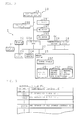
- FIG. 1 is a schematic diagram illustrating a processing system
- FIG. 2 is a block diagram illustrating a hardware group of a computer
- FIG. 3 is an explanatory diagram illustrating a record layout of an abnormality file
- FIG. 4 is an explanatory diagram illustrating a display image of abnormality information
- FIG. 5 is an explanatory diagram illustrating a record layout of an abnormality history file
- FIG. 6 is an explanatory diagram illustrating an image on a selection screen
- FIG. 7 is an explanatory diagram illustrating an image on a countermeasure information input screen
- FIG. 8 is an explanatory diagram illustrating a record layout of a countermeasure information file
- FIG. 9 is an explanatory diagram illustrating a hardware group of a server computer
- FIG. 10 is an explanatory diagram illustrating a record layout of an apparatus DB
- FIG. 11 is an explanatory diagram illustrating a record layout of a countermeasure information DB
- FIG. 12 is an explanatory diagram illustrating a display image of countermeasure information
- FIG. 13 is a flowchart illustrating a sequence of countermeasure information input processing
- FIG. 14 is a flowchart illustrating a sequence of countermeasure information display processing
- FIG. 15 is a schematic diagram illustrating a processing system according to Embodiment 2.
- FIG. 16 is a flowchart illustrating a sequence of countermeasure information display processing according to Embodiment 2;
- FIG. 17 is an explanatory diagram illustrating a record layout of an abnormality file according to Embodiment 3.
- FIG. 18 is an explanatory diagram illustrating an image of an abnormality information display screen
- FIG. 19 is an explanatory diagram illustrating a record layout of a countermeasure information file
- FIG. 20 is an explanatory diagram illustrating an image of a countermeasure information input screen
- FIG. 21 is an explanatory diagram illustrating a record layout of a countermeasure information DB according to Embodiment 2;
- FIG. 22 is a flowchart illustrating a sequence of countermeasure information input processing
- FIG. 23 is a flowchart illustrating a sequence of countermeasure information input processing
- FIG. 24 is a block diagram illustrating a hardware group of a server computer according to Embodiment 4.
- FIG. 25 is an explanatory diagram illustrating a record layout of a statistic DB
- FIG. 26 is an explanatory diagram illustrating a display image of countermeasure information
- FIG. 27 is a flowchart illustrating a statistic display processing
- FIG. 28 is a flowchart illustrating a statistic display processing
- FIG. 29 is an explanatory diagram illustrating a countermeasure information input screen
- FIG. 30 is an explanatory diagram illustrating a record layout of a countermeasure information file according to Embodiment 5;
- FIG. 31 is an explanatory diagram illustrating a record layout of a countermeasure information DB
- FIG. 32 is a flowchart illustrating a sequence of deletion processing
- FIG. 33 is an explanatory diagram illustrating a record layout of an abnormality file according to Embodiment 6;
- FIG. 34 is a flowchart illustrating a sequence of execution processing
- FIG. 35 is an explanatory diagram illustrating a record layout of an apparatus DB according to Embodiment 7;
- FIG. 36 is an explanatory diagram illustrating an image of a warning screen
- FIG. 37 is a flowchart illustrating a sequence of selection processing
- FIG. 38 is a flowchart illustrating a sequence of warning information display processing
- FIG. 39 is a schematic diagram illustrating a processing system according to Embodiment 8.
- FIG. 40 is a block diagram illustrating a hardware group of a computer according to Embodiment 9;
- FIG. 41 is an explanatory diagram illustrating a record layout of a statistic DB according to Embodiment 10.
- FIG. 42 is a flowchart illustrating a sequence of statistic display processing
- FIG. 43 is a flowchart illustrating a sequence of statistic display processing.
- FIG. 44 is an explanatory diagram illustrating a display image of countermeasure information.
- FIG. 1 is a schematic diagram illustrating a processing system.
- the processing system includes a computer 1 , a semiconductor treatment apparatus 20 , an information processing apparatus 2 , and the like.
- the semiconductor treatment apparatus 20 is an apparatus for performing a treatment for a semiconductor under control of the information processing apparatus 2 .
- the semiconductor treatment apparatus 20 is, for example, a film forming apparatus, a cleaning apparatus, an etching apparatus, or an exposure apparatus for forming an oxide film on a wafer. In Embodiment 1, it is assumed that the semiconductor treatment apparatus 20 is a film-forming apparatus 20 , but is not limited to that.
- the information processing apparatus 2 includes, for example, a computer embedded in the film-forming apparatus 20 , a personal computer (PC) or a personal digital assistant (PDA) mounted in the external side of the film-forming apparatus 20 , or the like.
- the information processing apparatus 2 is, for example, a computer 2 embedded in the film-forming apparatus 20 .
- the computer 1 connected to multiple computers 2 via a communication network N such as a local area network (LAN) or the Internet is, for example, a server computer or a personal computer.
- LAN local area network
- the Internet is, for example, a server computer or a personal computer.
- the computer 1 is a server computer 1 .
- the server computer 1 transmits and receives information between computers 2 A, 2 B, 2 C, . . . , and so on (hereinafter, representatively referred to as a computer 2 ) connected via a communication network N based on a protocol such as a hypertext transfer protocol (HTTP).
- HTTP hypertext transfer protocol
- the computers 2 A, 2 B, and 2 C are embedded in the film-forming apparatuses 20 A, 20 B, and 20 C, respectively (hereinafter representatively referred to as 20 ). For example, when an abnormality is generated in the film-forming apparatus 20 A, the computer 2 A displays abnormality information regarding the generated abnormality. A user inputs countermeasure information for addressing the abnormality to the computer 2 A. The computer 2 A transmits to the server computer 1 the input countermeasure information together with abnormality identification information (hereinafter referred to as abnormality ID) for identifying the abnormality.
- abnormality ID abnormality identification information
- Each semiconductor treatment apparatus 20 may be another type of apparatus.
- the semiconductor treatment apparatus 20 may be obtained by integrating the film-forming apparatus 20 A, the etching apparatus 20 B, and the exposure apparatus 20 C.
- each semiconductor treatment apparatus 20 is installed in a single facility such as a factory or a laboratory in Embodiment 1, the invention is not limited to that.
- the film-forming apparatuses 20 A and 20 B may be installed in a single factory, and the film-forming apparatus 20 C may be installed in another factory, so that they may be connected to each other via a communication network N.
- FIG. 2 is a block diagram illustrating a hardware group of the computer 2 .
- the computer 2 includes a central processing unit (CPU) 21 as a controller, a random access memory (RAM) 22 , an input section 23 , a display section 24 , a memory section 25 , a communication section 26 , a communication port 294 , a timepiece section 28 and the like.
- the film-forming apparatus 20 is connected to the computer 2 using the communication port 294 .
- the CPU 21 is connected to each section of the hardware through a bus 27 .
- the CPU 21 controls each section of the hardware and executes various software functionalities depending on a control program 25 P stored in the memory section 25 .
- the input section 23 is an input device such as a mouse, a keyboard, a control button, a switch, and a touch panel for controlling the film-forming apparatus 20 .
- the input section 23 outputs the input manipulation information to the CPU 21 .
- the display section 24 is a liquid crystal display, an organic electroluminescence (EL) display, or the like for displaying various types of information such as abnormality information in response to an instruction from the CPU 21 .
- EL organic electroluminescence
- the RAM 22 includes, for example, a static RAM (SRAM), a dynamic RAM (DRAM), a flash memory, or the like.
- the RAM 22 also serves as a memory section to temporarily store various data generated in the course of execution of various programs in the CPU 21 .
- the communication section 26 includes a wireless/wired LAN card and the like. The communication section 26 transmits or receives information to/from the server computer 1 via a communication network N.
- the timepiece section 28 outputs the date/time information to the CPU 21 .
- the memory section 25 includes, for example, a hard disk, a large-capacity flash memory, or the like.
- the memory section 25 stores an abnormality file 251 , a countermeasure information file 252 , and an abnormality history file 253 .
- the abnormality file 251 , the countermeasure information file 252 , and the abnormality history file 253 are stored in the memory section 25 .
- the invention is not limited to that.
- the abnormality file 251 , the countermeasure information file 252 , or the abnormality history file 253 may be stored in a server computer 1 or a database (hereinafter referred to as a DB) server (not illustrated), and the CPU 21 may read or store the data as necessary.
- a server computer 1 or a database (hereinafter referred to as a DB) server (not illustrated)
- the CPU 21 may read or store the data as necessary.
- the communication port 294 includes, for example, a universal serial bus (USB) port, a communication port based on a standard RS232C, or the like.
- the communication port 294 is used to transmit or receive information between the computer 2 and the film-forming apparatus 20 .
- the film-forming apparatus 20 includes a film formation processing section 29 , a stage control section 290 , a first sensor 291 , a second sensor 292 , a third sensor 293 , and the like.
- the film formation processing section 29 forms, for example, an oxide film or the like on a wafer.
- the stage control section 290 controls movement of a stage where the wafer is placed.
- the first to third sensors 291 to 293 are sensors for detecting a temperature of the film-forming apparatus 20 , a gas flow rate, a position of the stage, and the like. Although only a part of the functionalities of the film-forming apparatus 20 are described in Embodiment 1 for the sake of simplified description, other structures may also be included.
- FIG. 3 is an explanatory diagram illustrating a record layout of the abnormality file 251 .
- the abnormality file 251 stores abnormality information regarding abnormalities generated in the film-forming apparatus 20 by matching the abnormality ID.
- the abnormality file 251 includes an abnormality ID field and an abnormality information field.
- the abnormality ID field contains a unique ID for identifying abnormalities generated in the film-forming apparatus 20 .
- the abnormality information field contains abnormality information by matching the abnormality ID.
- an abnormality ID “1001” corresponds to abnormality information indicating a fact that the first sensor 291 that detects movement in the X-axis direction of the stage is not activated.
- an abnormality is identified using the abnormality ID.
- the invention is not limited to that.
- an abnormality may be identified using a combination of parts or sensors in the film formation processing section 29 .
- the abnormality ID “1001” may correspond to an abnormality in the “stage” and the “first sensor.”
- the abnormality ID “1002” may correspond to an abnormality in the “stage” and the “second sensor.”
- the abnormality ID “2003” may correspond to an abnormality in the “gas supply section” and the “third sensor.”
- FIG. 4 is an explanatory diagram illustrating a display image of the abnormality information.
- the film-forming apparatus 20 outputs the abnormality ID to the CPU 21 via the communication port 294 .
- the CPU 21 reads the abnormality information corresponding to the abnormality ID from the abnormality file 251 and displays the abnormality information on the display section 24 .
- the CPU 21 obtains date/time information output from the timepiece section 28 when the abnormality ID is output.
- the CPU 21 displays the obtained date/time information on the display section 24 as occurrence date/time.
- the abnormality ID, the abnormality information and the occurrence date/time are displayed.
- As the abnormality information of the abnormality ID “1001,” a notification “first sensor of stage is in response” is displayed.
- the image data and the template data for screen display are stored in the memory section 25 .
- the CPU 21 displays the countermeasure information display button 241 for displaying the countermeasure information on the display section 24 . The processing performed when the countermeasure information display button 241 is pressed will be described below.
- FIG. 5 is an explanatory diagram illustrating a record layout of the abnormality history file 253 .
- the abnormality history file 253 stores a history of the generated abnormality.
- the abnormality history file 253 includes an occurrence date/time field and an abnormality ID field.
- the occurrence date/time field contains the occurrence date/time at the time of occurrence of the abnormality.
- the abnormality ID field contains the abnormality ID by matching the occurrence date/time.
- the CPU 21 stores the abnormality ID and the occurrence date/time in the abnormality history file 253 when the abnormality ID is output from the film-forming apparatus 20 .
- FIG. 6 is an explanatory diagram illustrating an image of the selection screen.
- a command to display a selection screen for selecting a history of the abnormality generated in the past is input from the input section 23 .
- the CPU 21 receives a command to display the selection screen from the input section 23 , the CPU 21 reads the occurrence date/time and the abnormality ID from the abnormality history file 253 and displays them on the display section 24 .
- the CPU 21 displays occurrence date/time, the abnormality ID, and check boxes for selection on the selection screen.
- a user inputs the countermeasure information from the input section 23 and selects one of the occurrence date/times and one of the abnormality IDs and presses the OK-button.
- FIG. 7 is an explanatory diagram illustrating an image of the countermeasure information input screen.
- the CPU 21 receives the occurrence date/time and the abnormality ID selected on the selection screen and reads the abnormality information corresponding to the abnormality ID from the abnormality file 251 . As illustrated in FIG. 7 , the CPU 21 displays the occurrence date/time, the abnormality ID, and the abnormality information on the countermeasure information input screen. In addition, the CPU 21 displays a screen for prompting input of the user ID. Furthermore, the CPU 21 displays the countermeasure information input box 242 for inputting the countermeasure information.
- the user ID is identification information for identifying a user who inputs the countermeasure information. The CPU 21 receives the user ID input from the input section 23 . Instead of the user ID, information, such as a name, that can be used to identify a user may be input.
- a user inputs the countermeasure information to the countermeasure information input box 242 from the input section 23 .
- the countermeasure information is input by a text sentence when a user confronts an abnormality.
- the input of the countermeasure information is not limited to the text sentence.
- an application file such as an image file, a voice file, or a portable document format (PDF, registered trademark) file may also be input.
- PDF portable document format
- the CPU 21 receives the input user ID and the input countermeasure information.
- the CPU 21 stores the input countermeasure information and the input user ID in the countermeasure information file 252 by matching the occurrence date/time and the abnormality ID.
- FIG. 8 is an explanatory diagram illustrating a record layout of the countermeasure information file 252 .
- the countermeasure information file 252 includes an occurrence date/time field, an abnormality ID field, a countermeasure ID field, a countermeasure information field, a user ID field, and the like.
- the countermeasure information field contains the countermeasure information input to the countermeasure information input box 242 by matching the occurrence date/time and the abnormality ID.
- the countermeasure ID field contains unique identification information for identifying the countermeasure information.
- the user ID field contains the user ID of a user who inputs the countermeasure information on the countermeasure information input screen by matching the countermeasure information.
- the CPU 21 transmits information containing the abnormality ID and the countermeasure information stored in the countermeasure information file 252 to the server computer 1 via the communication section 26 at an appropriate timing.
- the countermeasure information file 252 is prepared in the memory section 25 in Embodiment 1, the invention is not limited to that.
- the countermeasure information and the abnormality ID may be temporarily stored in the RAM 22 without using the memory section 25 and may be transmitted to the server computer 1 .
- a data layout of the file and the DB referred to in Embodiment 1 is just for illustrative purposes, and any other type may be employed if a relationship between the data is maintained.
- FIG. 9 is an explanatory diagram illustrating a hardware group of the server computer 1 .
- the server computer 1 includes a CPU 11 as a controller, a RAM 12 , an input section 13 , a display section 14 , a communication section 16 , a timepiece section 18 , a memory section 15 , and the like.
- the CPU 11 is connected to each section of the hardware via a bus 17 .
- the CPU 11 controls each section of the hardware and executes a software functionality based on a control program 15 P stored in the memory section 15 .
- the timepiece section 18 outputs date/time to the CPU 11 .
- the communication section 16 is a gateway that performs a functionality of the firewall or the like and is used to transmit or receive information between a computer 2 and other server computers (not illustrated) via a protocol such as HTTP.
- the input section 13 is an input device such as a mouse, a keyboard, and a touch panel.
- the input section 13 outputs the input manipulation information to the CPU 11 .
- the display section 14 includes a liquid crystal, an organic EL display, or the like and displays various types of information such as abnormality information in response to an instruction from the CPU 11 .
- the RAM 12 includes, for example, an SRAM, a DRAM, a flash memory, or the like.
- the RAM 12 also serves as a memory section and temporarily stores various data generated when the CPU 11 executes various programs.
- the memory section 15 includes, for example, a hard disk, a large-capacity memory, or the like.
- the memory section 15 stores an apparatus DB 151 , a countermeasure information DB 152 , and the like, in addition to the control program 15 P described above.
- the apparatus DB 151 and the countermeasure information DB 152 are stored in the memory section 15 .
- the apparatus DB 151 or the countermeasure information DB 152 may be stored in a DB server (not illustrated), and the CPU 11 may read or store data using a structured query language (SQL).
- SQL structured query language
- FIG. 10 is an explanatory diagram illustrating a record layout of the apparatus DB 151 .
- the apparatus DB 151 contains a computer ID field, a film-forming apparatus ID field and an address field.
- the computer ID field contains unique identification information for identifying the computer 2 .
- the film-forming apparatus ID field contains unique identification information for identifying the film-forming apparatus 20 by matching the computer ID.
- the address field contains an address of the computer 2 , such as an Internet protocol (IP) address or a media access control (MAC) address, by matching the computer ID.
- IP Internet protocol
- MAC media access control
- FIG. 11 is an explanatory diagram illustrating a record layout of the countermeasure information DB 152 .
- the countermeasure information DB 152 stores an occurrence date/time field, an abnormality ID field, a countermeasure ID field, a countermeasure information field, a user ID field, a computer ID field, and the like.
- the CPU 11 stores the occurrence date/time, the abnormality ID, the countermeasure ID, the countermeasure information, the user ID, and the computer ID in the countermeasure information DB 152 when they are transmitted from the computer 2 via the communication section 16 .
- the countermeasure information regarding the abnormality ID “1001” is transmitted from the computer 2 A having the computer ID “P001” and the computer 2 B having the computer ID “P002.”
- the countermeasure information for each abnormality ID is collected from the computers 2 of each film-forming apparatus 20 .
- FIG. 12 is an explanatory diagram illustrating a display image of the countermeasure information.
- a user inputs the countermeasure information display button 241 illustrated in FIG. 4 using the input section 23 when a user desires to obtain the countermeasure information that has been already collected at the time of occurrence of an abnormality.
- the CPU 21 transmits a request for acquiring the computer ID, the abnormality ID, and the countermeasure information to the server computer 1 via the communication section 26 .
- the CPU 11 of the server computer 1 receives the request for acquiring the computer ID, the abnormality ID, and the countermeasure information via the communication section 16 .
- the CPU 11 selects the countermeasure information and the countermeasure ID corresponding to the abnormality ID from the countermeasure information DB 152 .
- the CPU 11 reads the address corresponding to the computer ID from the apparatus DB 151 .
- the CPU 11 transmits the read countermeasure ID and the read countermeasure information to the computer 2 corresponding to the read address.
- the CPU 21 of the computer 2 displays the received countermeasure ID and the received countermeasure information on the display section 24 .
- the countermeasure information for the abnormality ID “1001” the countermeasure information of the countermeasure IDs “N1001” and “N1008” is displayed.
- FIG. 13 is a flowchart illustrating a sequence of the countermeasure information input processing.
- the CPU 21 receives the abnormality ID from the abnormal film-forming apparatus 20 via the communication port 294 (step S 131 ).
- the CPU 21 reads the abnormality information corresponding to the abnormality ID from the abnormality file 251 (step S 132 ).
- the CPU 21 displays the abnormality ID, the abnormality information, the occurrence date/time of the abnormality based on the date/time information obtained from the timepiece section 28 , and the countermeasure information display button 133 (step S 133 ).
- the CPU 21 stores the occurrence date/time and the abnormality ID in the abnormality history file 253 by matching each other (step S 134 ).
- the CPU 21 reads the occurrence date/time and the abnormality ID stored in the abnormality history file 253 and displays them on the display section 24 .
- the CPU 21 receives, via the input section 23 , the user's selection of the occurrence date/time and the abnormality ID desired to input the countermeasure information (step S 135 ).
- the CPU 21 reads the abnormality information corresponding to the selected occurrence date/time and the selected abnormality ID from the abnormality file 251 .
- the CPU 21 displays the occurrence date/time, the abnormality ID, and the abnormality information on the countermeasure information input screen (step S 136 ).
- the CPU 21 displays the countermeasure information input box 242 on the display section 24 .
- the CPU 21 receives the user ID and the countermeasure information from the input section 23 (step S 137 ).
- the CPU 21 generates a countermeasure ID corresponding to the input countermeasure information (step S 138 ).
- the CPU 21 stores the occurrence date/time, the abnormality ID, the countermeasure ID, the countermeasure information, and the user ID in the countermeasure information file 252 (step S 139 ). Then, the CPU 21 transmits (outputs) the occurrence date/time, the abnormality ID, the countermeasure ID, the countermeasure information, the user ID, and the computer ID to the server computer 1 via the communication section 26 (step S 1310 ).
- FIG. 14 is a flowchart illustrating a sequence of the countermeasure information display processing.
- the CPU 11 receives the occurrence date/time, the abnormality ID, the countermeasure ID, the countermeasure information, the user ID, and the computer ID transmitted from the computer 2 (step S 141 ).
- the CPU 11 stores the received occurrence date/time, the received abnormality ID, the received countermeasure ID, the received countermeasure information, the received user ID, and the received computer ID in the countermeasure information DB 152 (step S 142 ).
- the CPU 21 of the computer 2 receives an input of the countermeasure information display button 241 from the input section 23 .
- the CPU 21 transmits a request for acquiring the computer ID, the abnormality ID, and the countermeasure information to the server computer 1 (step S 143 ).
- the CPU 11 of the server computer 1 receives the request for acquiring the computer ID, the abnormality ID, and the countermeasure information.
- the CPU 11 reads the countermeasure ID and the countermeasure information corresponding to the received abnormality ID from the countermeasure information DB 152 (step S 144 ).
- the CPU 11 reads an address corresponding to the received computer ID from the apparatus DB 151 (step S 145 ).
- the CPU 11 transmits the read countermeasure ID and the read countermeasure information to a computer 2 corresponding to the read address (step S 146 ).
- the CPU 21 of the computer 2 receives (acquires) the countermeasure ID and the countermeasure information (step S 147 ).
- the CPU 21 displays the received countermeasure ID and the received countermeasure information together with the abnormality ID, the abnormality information, and the occurrence date/time (step S 148 ).
- the CPU 21 displays the received countermeasure ID and the received countermeasure information together with the abnormality ID, the abnormality information, and the occurrence date/time (step S 148 ).
- the computer 2 transmits the request for acquiring the countermeasure information to the server computer 1
- the server computer 1 transmits the corresponding countermeasure information.
- the CPU 11 of the server computer 1 may transmit the countermeasure information corresponding to the abnormality ID to each computer 2 on a regular basis such as every three hours.
- Each computer 2 may store the countermeasure information corresponding to the received abnormality ID in the memory section 25 .
- the CPU 21 of the computer 2 may perform a control action such that the countermeasure information corresponding to the abnormality ID is read from the memory section 25 and is displayed.
- FIG. 15 is a schematic diagram illustrating a processing system according to Embodiment 2.
- the computers 2 A, 2 B, 2 C, . . . , and so on are connected to each other via a communication network N in peer-to-peer manner.
- the countermeasure information is input to the computer 2 A, and the countermeasure information file 252 is updated, the updated countermeasure information is also transmitted to other computers 2 B and 2 C.
- the computer 2 A displays the countermeasure information by referencing the countermeasure information file 252 by itself.
- FIG. 16 is a flowchart illustrating a sequence of the countermeasure information display processing according to Embodiment 2.
- the CPU 21 receives the user ID and the countermeasure information input from the input section 23 (step S 161 ).
- the CPU 11 generates the countermeasure ID for identifying the countermeasure information (step S 162 ).
- the CPU 11 stores the occurrence date/time, the abnormality ID, the countermeasure ID, the countermeasure information, the user ID, and the computer ID in the countermeasure information file 252 (step S 163 ).
- the CPU 21 transmits, to other computers 2 , the occurrence date/time, the abnormality ID, the countermeasure ID, the countermeasure information, the user ID, and the computer ID stored newly (step S 164 ).
- each computer 2 transmits the updated data to other computers 2 when the countermeasure information file 252 is updated.
- the CPU 21 of the computer 2 receives the occurrence date/time, the abnormality ID, the countermeasure ID, the countermeasure information, the user ID, and the computer ID transmitted from other computers 2 (step S 165 ).
- the CPU 21 stores such received information in the countermeasure information file 252 (step S 166 ).
- the CPU 21 receives an input of the countermeasure information display button 241 illustrated in FIG. 4 from the input section 23 (step S 167 ).
- the CPU 21 reads the countermeasure information and the countermeasure ID corresponding to the abnormality ID from the countermeasure information file 252 (step S 168 ).
- the CPU 21 displays the read countermeasure information and the read countermeasure ID on the display section 24 (step S 169 ). As a result, it is possible to share the countermeasure information between each computer 2 with a simplified structure.
- Embodiment 2 except for those described above, other structures are the same as those in Embodiment 1. Therefore, the same reference numerals apply to corresponding elements, and their descriptions are omitted.
- FIG. 17 is an explanatory diagram illustrating a record layout of the abnormality file 251 according to Embodiment 3.
- the abnormality file 251 contains an abnormality ID field, an abnormality information field, a countermeasure item field, a cause-of-abnormality field, and the like.
- the countermeasure item field stores multiple candidate countermeasure items at the time of abnormality by matching the abnormality ID. According to Embodiment 3, for example, three countermeasure items are stored.
- the countermeasure items may include “retry,” “processing continued,” and “reboot.” In each of the candidate countermeasure items, details of the countermeasure item are described by matching the abnormality ID.
- the cause-of-abnormality field contains multiple causes of abnormality by matching the abnormality ID.
- the causes of abnormality may include “design failure,” “adjustment failure,” and the like.
- FIG. 18 is an explanatory diagram illustrating an image of the abnormality information display screen.
- the abnormality ID, the abnormality information, and multiple candidate countermeasure items are displayed.
- the CPU 21 displays a description of each countermeasure item and the candidate countermeasure item corresponding to the abnormality ID on the display section 24 with reference to the abnormality file 251 . For example, as a description of the countermeasure item “retry,” a message “stage will be lifted again in case of ‘retry’” may be displayed.
- a user inputs one of the countermeasure items from the input section 23 .
- the CPU 21 receives the countermeasure item input from the input section 23 .
- the CPU 21 outputs a signal corresponding to the countermeasure item to the film-forming apparatus 20 .
- the film-forming apparatus 20 controls the film formation processing section 29 or the stage control section 290 in response to the signal corresponding to the countermeasure item.
- the CPU 21 stores the manipulation data input from the input section 23 in the memory section 25 by matching the occurrence date/time and the abnormality ID after an abnormality occurs in the film-forming apparatus 20 until an output of the abnormality ID stops, from occurrence of the abnormality to removal of the abnormality, or from occurrence of the abnormality to a predetermined elapsed time.
- other manipulation data input from the film-forming apparatus 20 may also be stored in the memory section 25 .
- the manipulation data input from the input section 23 are stored in the memory section 25 from occurrence of the abnormality to a predetermined elapsed time (for example, 5 minutes).
- the CPU 21 stores, in the memory section 25 , the setup data obtained before occurrence of an abnormality and the data obtained when an abnormality occurs (hereinafter, referred to as sensor data) of the first to third sensors 291 , 292 , and 293 by matching the occurrence date/time and the abnormality ID.
- FIG. 19 is an explanatory diagram illustrating a record layout of the countermeasure information file 252 .
- a countermeasure item field contains the countermeasure item selected by a user on the abnormality information display screen of FIG. 18 .
- the CPU 21 stores the countermeasure item in the countermeasure information file 252 by matching the occurrence date/time and the abnormality ID.
- the sensor data field, the manipulation data field, the cause-of-abnormality field, and the replacement part ID field will be described below.
- FIG. 20 is an explanatory diagram illustrating an image of the countermeasure information input screen.
- data on the replacement parts and the cause of an abnormality may be input.
- a user inputs the replacement part ID using the input section 23 when a failed part is to be replaced in the case of an abnormality.
- the CPU 21 receives the replacement part ID input through the input section 23 .
- names of the replacement parts may be listed, and one of them may be selected.
- the CPU 21 stores the replacement part ID in the replacement part ID field of the countermeasure information file 252 by matching the occurrence date/time and the abnormality ID.
- the CPU 21 reads multiple causes of abnormality corresponding to the abnormality ID from the abnormality file 251 .
- the CPU 21 displays multiple candidate causes of abnormality on the display section 24 . As illustrated in FIG. 20 , multiple candidate causes of abnormality are displayed together with a check box as illustrated in FIG. 20 . A user selects one of the displayed causes of abnormality. In Embodiment 3, for the sake of simplified description, it is assumed that one of the causes of abnormality is selected. However, multiple causes of abnormality may also be selected.
- the CPU 21 receives the selected cause of abnormality from the input section 23 .
- the CPU 21 stores the received cause of abnormality in the cause-of-abnormality field of the countermeasure information file 252 by matching the occurrence date/time and the abnormality ID.
- the CPU 21 displays information on whether or not the countermeasure information file 252 stores the manipulation data obtained from the input section 23 and stored in the memory section 25 by matching the occurrence date/time and the abnormality ID at the time of occurrence of abnormality.
- a check box “attach manipulation data” is selected.
- the CPU 21 stores the manipulation data of the memory section 25 in the manipulation data field of the countermeasure information file 252 by matching the occurrence date/time and the abnormality ID.
- the CPU 21 displays information on whether or not the countermeasure information file 252 stores the setup data and the abnormality data of the first to third sensors 291 , 292 , and 293 stored at the time of occurrence of abnormality by matching the occurrence date/time and the abnormality ID.
- the setup data and the abnormality data of the first sensor 291 are stored, a user selects the check box “attach first sensor data.”
- the CPU 21 stores such data in the sensor data field of the countermeasure information file 252 by matching the occurrence date/time and the abnormality ID.
- the CPU 21 transmits to the server computer 1 the occurrence date/time, the abnormality ID, the countermeasure ID, the countermeasure information, the user ID, the countermeasure information, the sensor data, the manipulation data, the cause of abnormality, the replacement part ID, and the computer ID.
- FIG. 21 is an explanatory diagram illustrating a record layout of the countermeasure information DB 152 according to Embodiment 2.
- a countermeasure information field a sensor data field, a manipulation data field, a cause-of-abnormality field, and a replacement part ID field are provided.
- the CPU 11 of the server computer 1 stores the occurrence date/time, the abnormality ID, the countermeasure ID, the countermeasure information, the user ID, the countermeasure item, the sensor data, the manipulation data, the cause of abnormality, the replacement part ID, and the computer ID transmitted from the computer 2 .
- various types of know-how are accumulated in each computer 2 .
- FIGS. 22 and 23 are flowcharts illustrating a sequence of the countermeasure information input processing.
- the CPU 21 receives the abnormality ID from the abnormal film-forming apparatus 20 via the communication port 294 (step S 221 ).
- the CPU 21 reads the abnormality information corresponding to the abnormality ID from the abnormality file 251 (step S 222 ).
- the CPU 21 reads multiple countermeasure items corresponding to the abnormality IDs from the abnormality file 251 (step S 223 ).
- the CPU 21 displays the abnormality ID, the abnormality information, the abnormality occurrence date/time based on the date/time information obtained from the timepiece section 28 , multiple countermeasure items, and the countermeasure information display button 133 on the abnormality information display screen 24 (step S 224 ).
- the CPU 21 stores the manipulation data input from a manipulation system or a control system (not illustrated) of the input section 23 or the film-forming apparatus 20 in the memory section 25 by matching the date/time information output from the timepiece section 28 (step S 225 ).
- the CPU 21 stores, in the memory section 25 , the setup data stored in the memory section 25 of the first to third sensors 291 , 292 , and 293 in advance and the abnormality data output from the first to third sensors 291 , 292 , and 293 at the time of abnormality by matching each other (step S 226 ).
- the CPU 21 receives the one selected from multiple countermeasure items via the input section 23 (step S 227 ).
- the CPU 21 stores in the abnormality history file 253 the occurrence date/time, the abnormality ID, the countermeasure item, the manipulation data, and the setup data and the abnormality data of the first to third sensors 291 , 292 , and 293 by matching each other (step S 228 ).
- the CPU 21 determines whether or not a request for displaying the countermeasure information is received based on the input of the countermeasure information display button 241 (step S 229 ). If it is determined that the request for displaying the countermeasure information is received (YES in step S 229 ), the CPU 21 performs the processing of FIG. 14 to display the countermeasure information on the display section 24 (step S 231 ). If it is determined that the request for displaying the countermeasure information is not received (NO in step S 229 ), the CPU 21 advances the process to step S 232 .
- the CPU 21 reads the occurrence date/times and the abnormality IDs stored in the abnormality history file 253 and displays them on the display section 24 .
- the CPU 21 receives a selection of the occurrence date/time and a selection of the abnormality ID desired to input the countermeasure information via the input section 23 (step S 232 ).
- the CPU 21 reads the abnormality information corresponding to the selected occurrence date/time and the selected abnormality ID from the abnormality file 251 .
- the CPU 21 displays the occurrence date/time, the abnormality ID, and the abnormality information on the countermeasure information input screen (step S 233 ).
- the CPU 21 displays the countermeasure information input box 242 on the display section 24 .
- the CPU 21 receives the user ID and the countermeasure information from the input section 23 (step S 234 ).
- the CPU 21 generates a countermeasure ID corresponding to the input countermeasure information (step S 235 ).
- the CPU 21 reads multiple causes of abnormality corresponding to the abnormality ID from the abnormality file 251 (step S 236 ).
- the CPU 21 displays multiple causes of abnormality on the display section 24 (step S 237 ).
- the CPU 21 receives a selection of the cause of abnormality via the input section 23 (step S 238 ).
- the CPU 21 receives an input of the replacement part ID (step S 239 ). If there is no replacement part, it is not necessary to input the replacement part ID.
- the CPU 21 receives, via the input section 23 , information on whether or not the manipulation data is attached (step S 2310 ).
- the CPU 21 receives, via the input section 23 , information on whether or not the data of the first to third sensors 291 , 292 , and 293 are attached (step S 2311 ).
- the CPU 21 stores the occurrence date/time, the abnormality ID, the countermeasure ID, the countermeasure information, the countermeasure item, the user ID, the cause of abnormality, the replacement part ID, the manipulation data, the setup data, and the abnormality data in the countermeasure information file 252 (step S 2312 ). If the information for attaching the manipulation data is not input in step S 2310 , the manipulation data may not be stored in the countermeasure information file 252 . If the information on whether or not the data of the first to third sensors 291 , 292 , and 293 is not received in step S 2311 , the setup data and the abnormality data may not be stored in the countermeasure information file 252 .
- the CPU 21 transmits the occurrence date/time, the abnormality ID, the countermeasure ID, the countermeasure information, the countermeasure item, the user ID, the cause of abnormality, the replacement part ID, the manipulation data, the setup data, the abnormality data, and the computer ID to the server computer 1 via the communication section 26 (step S 2313 ).
- the CPU 11 of the server computer 1 receives the occurrence date/time, the abnormality ID, the countermeasure ID, the countermeasure information, the user ID, the cause of abnormality, the replacement part ID, the manipulation data, the setup data, the abnormality data, and the computer ID via the communication section 16 .
- the CPU 11 stores the received occurrence date/time, the received abnormality ID, the received countermeasure ID, the received countermeasure information, the received user ID, the received cause of abnormality, the received replacement part ID, the received manipulation data, the received setup data, the received abnormality data, and the received computer ID in the countermeasure information DB 152 (step S 2314 ).
- various types of information can be accumulated as know-how.
- Embodiment 3 except for those described above, other structures are the same as those of Embodiments 1 and 2. Therefore, the same reference numerals apply to corresponding elements, and their descriptions are omitted.
- FIG. 24 is a block diagram illustrating a hardware group of the server computer 1 according to Embodiment 4.
- a statistic DB 153 is newly provided in the memory section 15 .
- FIG. 25 is an explanatory diagram illustrating a record layout of the statistic DB 153 .
- the statistic DB 153 contains an abnormality ID field, a countermeasure item field, a cause-of-abnormality field, a number-of-events field and a percentage field.
- the countermeasure item field contains multiple countermeasure items by matching the abnormality ID.
- the number-of-events field corresponding to the countermeasure item contains the number of events of the selected countermeasure item by matching the countermeasure item.
- the CPU 11 of the server computer 1 counts the number of countermeasure items corresponding to the abnormality ID with reference to the countermeasure information file 252 .
- the CPU 11 stores, in the statistic DB 153 , the count value for each countermeasure item as the number of events.
- the CPU 11 computes a percentage of each countermeasure item by subtracting the number of events of each countermeasure item from a total number of the countermeasure items and multiplying the result by 100.
- the CPU 11 stores the computed percentage in the statistic DB 153 by matching the abnormality ID and the countermeasure item.
- the cause-of-abnormality field contains multiple causes of abnormality by matching the abnormality ID.
- the number-of-events field corresponding to the cause of abnormality contains a count of the selected cause of abnormality by matching the cause of abnormality.
- the CPU 11 of the server computer 1 counts the number of causes of abnormality corresponding to the abnormality ID with reference to the countermeasure information file 252 .
- the CPU 11 stores in the statistic DB 153 the count result for each cause of abnormality as the number of events.
- the CPU 11 computes a percentage of each cause of abnormality by subtracting the number of events of each countermeasure item from a total number of the countermeasure items and multiplying the result by 100.
- the CPU 11 stores the computed percentage in the statistic DB 153 by matching the abnormality ID and the countermeasure item.
- FIG. 26 is an explanatory diagram illustrating a display image of the countermeasure information.
- a statistic of the countermeasure item and a statistic of the cause of abnormality are displayed.
- the CPU 11 of the server computer 1 reads the countermeasure item corresponding to the abnormality ID, the number of events and the percentage of the countermeasure item, the cause of abnormality, and the number of events and the percentage of the cause of abnormality with reference to the statistic DB 153 .
- the CPU 11 transmits the countermeasure item, the number of events and the percentage of the countermeasure item, the cause of abnormality, and the number of events and the percentage of the cause of abnormality to the computer 2 .
- the CPU 21 of the computer 2 displays the number of events and the percentage of each countermeasure item and the number of events and the percentage of the cause of abnormality as illustrated in FIG. 26 .
- the CPU 21 returns to the abnormality information display screen of FIG. 18 .
- an appropriate countermeasure item based on a statistic of the past countermeasure item.
- a statistic both the number of events and the percentage are displayed.
- the invention is not limited to that. Any one of the number of events and the percentage may be displayed, and the statistic may be displayed using a graph or the like.
- both the statistic of the countermeasure item and the statistic of the cause of abnormality are displayed. However, either one of them may also be displayed.
- the replacement part ID, the manipulation data, and the setup data and the abnormality data of the first to third sensors 291 , 292 , and 293 may also be displayed on the display section 24 .
- the CPU 11 of the server computer 1 reads the countermeasure ID corresponding to the abnormality ID, the replacement part ID, the manipulation data, and the setup data and the abnormality data of the first to third sensors 291 , 292 , and 293 with reference to the countermeasure information DB 152 .
- the CPU 11 transmits to the computer 2 the countermeasure ID, the replacement part ID, the manipulation data, and the setup data and the abnormality data of the first to third sensors 291 , 292 , and 293 .
- the CPU 21 of the computer 2 displays the received countermeasure ID, the received replacement part ID, the received manipulation data, the received setup data and abnormality data of the first to third sensors 291 , 292 , and 293 .
- FIGS. 27 and 28 are flowcharts illustrating a statistic display processing.
- the CPU 11 receives the abnormality ID, the countermeasure item, and the cause of abnormality transmitted from the computer 2 (step S 271 ).
- the CPU 11 counts the countermeasure item and the cause of abnormality relating to the abnormality ID with reference to the countermeasure information DB 152 and stores the counted number of events in the statistic DB 153 (step S 272 ).
- the counting may be performed on a regular basis (for example, every one hour) or may be performed when the abnormality ID, the countermeasure item, and the cause of abnormality are transmitted from the computer 2 .
- the CPU 11 computes the percentages of the countermeasure item and the cause of abnormality based on the counted number of events and stores the computed percentages in the statistic DB 153 (step S 273 ).
- the CPU 21 of the computer 2 receives an input of the countermeasure information display button 241 from the input section 23 .
- the CPU 21 transmits to the server computer 1 a request for acquiring the computer ID, the abnormality ID, and the countermeasure information (step S 274 ).
- the CPU 11 of the server computer 1 receives the request for acquiring the computer ID, the abnormality ID, the countermeasure information, the replacement part ID, the manipulation data, and the setup data and abnormality data of the first to third sensors 291 , 292 , and 293 .
- the CPU 11 reads, from the countermeasure information DB 152 , the countermeasure ID, the countermeasure information, the replacement part ID, and the manipulation data corresponding to the received abnormality ID, and the setup data and abnormality data of the first to third sensors 291 , 292 , and 293 (step S 275 ).
- the CPU 11 reads an address corresponding to the received computer ID from the apparatus DB 151 (step S 276 ).
- the CPU 11 transmits the countermeasure ID, the countermeasure information, the replacement part ID, the manipulation data, and the setup data and abnormality data of the first to third sensors 291 , 292 , and 293 to a computer 2 destined to the read address (step S 277 ).
- the CPU 11 reads the number of events and the percentage of the countermeasure item corresponding to the abnormality ID and the number of events and the percentage of the cause of abnormality from the statistic DB 153 and transmits them to the computer 2 (step S 278 ).
- the CPU 21 of the computer 2 receives the countermeasure ID, the countermeasure information, the replacement part ID, the manipulation data, and the setup data and abnormality data of the first to third sensors 291 , 292 , and 293 (step S 279 ).
- the CPU 21 displays the countermeasure ID, the countermeasure information, the received replacement part ID, the manipulation data, and the setup data and abnormality data of the first to third sensors 291 , 292 , and 293 together with the abnormality ID, the abnormality information, and the occurrence date/time (step S 281 ).
- the CPU 21 receives the number of events and the percentage of the countermeasure item corresponding to the abnormality ID and the number of events and the percentage of the cause of abnormality (step S 282 ).
- the CPU 21 displays the number of events and the percentage of the countermeasure item corresponding to the abnormality ID and the number of events and the percentage of the causes of abnormality on the display section 24 (step S 283 ).
- Embodiment 4 except for those described above, other structures are the same as those of Embodiments 1 to 3. Therefore, the same numerals apply to corresponding elements, and their descriptions are omitted.
- FIG. 29 is an explanatory diagram illustrating a countermeasure information input screen.
- a user may input a preservation period of the countermeasure information via an input section 23 .
- a deletion date/time may be input.
- the CPU 21 displays information for inputting the preservation period from the memory section 25 . As illustrated in FIG.
- the preservation period may include, for example, “PERMANENT” in which the countermeasure information corresponding to the abnormality ID is permanently stored, “YEAR/MONTH/DATE” in which the countermeasure information is stored to a predetermined date/time, and “NUMBER OF MONTHS” in which the countermeasure information is stored for a predetermined number of months.
- a user selects the “PERMANENT” from the input section 23 when it is considered that the countermeasure information is important, and it is necessary to store the countermeasure information for a long time.
- a user inputs the date/time or the number of months desired for preservation from the input section 23 .
- FIG. 30 is an explanatory diagram illustrating a record layout of the countermeasure information file 252 according to Embodiment 5. Referring to FIG. 30 , a preservation period field is newly provided. The CPU 21 stores the preservation period input via the input section 23 by matching the occurrence date/time and the abnormality ID. In the example of FIG. 30 , the countermeasure information corresponding to the abnormality ID “1001” generated at 12:55:20, Sep. 16, 2010 is permanently stored.
- FIG. 31 is an explanatory diagram illustrating a record layout of the countermeasure information DB 152 .
- a preservation period field is newly provided.
- the CPU 11 of the server computer 1 stores in the countermeasure information DB 152 the preservation period transmitted by matching the occurrence date/time and the abnormality ID.
- the CPU 11 deletes a record after the preservation period stored in the preservation period field elapses with reference to the date/time information output from the timepiece section 28 .
- an operator may appropriately delete less important countermeasure information from the input section 13 or other non-illustrated computers.
- FIG. 32 is a flowchart illustrating a sequence of the deletion processing.
- the CPU 21 displays the countermeasure information input screen on the display section 24 as illustrated in FIG. 29 (step S 321 ).
- the CPU 21 receives the countermeasure information and the preservation period via the input section 23 (step S 322 ).
- the CPU 21 stores in the countermeasure information file 252 the occurrence date/time, the abnormality ID, the countermeasure information, and the preservation period (step S 323 ).
- the CPU 21 transmits to the server computer 1 the occurrence date/time, the abnormality ID, the countermeasure information, the preservation period, and the computer ID (step S 324 ).
- the CPU 11 of the server computer 1 receives the occurrence date/time, the abnormality ID, the countermeasure information, the preservation period, and the computer ID (step S 325 ).
- the CPU 11 stores the occurrence date/time, the abnormality ID, the countermeasure information, the preservation period, and the computer ID (step S 326 ).
- the CPU 11 obtains the date/time information from the timepiece section 18 (step S 327 ).
- the CPU 11 determines whether or not there is countermeasure information whose preservation period elapsed with reference to the date/time information and the preservation period field in the countermeasure information DB 152 (step S 328 ). If it is determined that there is no countermeasure information whose preservation period elapsed (NO in step S 328 ), the CPU 11 advances to step S 327 and repeats the process.
- the countermeasure information whose preservation period is stored as “PERMANENT” may not be processed.
- step S 328 the CPU 11 deletes the countermeasure information whose preservation period has elapsed (step S 329 ). Specifically, a record containing the countermeasure information corresponding to the occurrence date/time and abnormality ID whose preservation period has elapsed is deleted from the countermeasure information DB 152 . As a result, only more important countermeasure information and related data are provided to other computers 2 , and it is possible to improve the efficiency of the countermeasure.
- the CPU 21 may delete a record relating to the countermeasure information whose preservation period has elapsed with reference to the preservation period field of the countermeasure information file and the date/time information output from the timepiece section 28 .
- Embodiment 5 except for those described above, other structures are the same as those of Embodiments 1 to 4. Therefore, the same reference numerals apply to those corresponding elements, and their descriptions are omitted.
- FIG. 33 is an explanatory diagram illustrating a record layout of the abnormality file 251 according to Embodiment 6.
- the execution command field contains an execution command for the film-forming apparatus 20 corresponding to the abnormality ID and the countermeasure item.
- an execution command for lifting a stage again is stored in the stage control section 290 .
- the CPU 21 outputs the execution command to the film-forming apparatus 20 via the communication port 294 .
- the film-forming apparatus 20 performs control such that the stage control section 290 is lifted in response to the execution command.
- a command for continuing the processing by neglecting the abnormality information for the abnormality ID is output.
- the CPU 21 outputs a command for continuing the processing to the film-forming apparatus 20 via the communication port 294 .
- the film-forming apparatus 20 continuously performs the next processing regardless of whether or not the first sensor 291 of the stage reacts.
- the countermeasure item “REBOOT” a command for turning off a power supply of the computer 2 and the film-forming apparatus 20 and turning them on again is output.
- the CPU 21 stops the power supply to the film-forming apparatus 20 and then executes the rebooting of the computer 2 .
- the CPU 21 starts to supply power to the film-forming apparatus 20 after the rebooting.
- the CPU 21 selects the countermeasure information having the greatest number of events or the highest percentage based on the statistic of Embodiment 4 and reads the execution command corresponding to the countermeasure item from the abnormality file 251 .
- the CPU 21 performs a processing of the film-forming apparatus 20 based on the read execution command. For example, when the percentage of the countermeasure item “RETRY” is 95% or higher, the processing is executed based on the execution command relating to the “RETRY” when abnormality occurs.
- FIG. 34 is a flowchart illustrating an execution processing sequence.
- the CPU 21 transmits a request for acquiring the computer ID, the abnormality ID, and the countermeasure information to the server computer 1 as described in step S 274 (step S 341 ).
- the CPU 21 receives the number of events and the percentage of each countermeasure item from the server computer 1 (step S 342 ).
- the CPU 21 reads a threshold value of the number of events and a threshold value of the percentage stored in advance from the memory section 25 (step S 343 ).
- the threshold value of the number of events is a value related to a total number of the events of overall countermeasure items and may be set to, for example, “30.”
- the threshold value of the percentage is a value related to a percentage of the number of events of a certain countermeasure item against the number of events of overall countermeasure items and may be set to, for example, 90%.
- the CPU 21 computes a total number of events of the countermeasure item received in step S 342 .
- the CPU 21 determines whether or not the total number of events exceeds a threshold value of the number of events read in step S 343 (step S 344 ).
- a threshold value of the number of events it is assumed that the total number of events is compared with a threshold value of the number of events.
- the invention is not limited thereto. For example, a maximum number of events of the countermeasure item may be compared with the threshold value of the number of events. If it is determined that the total number of events exceeds the threshold value of the number of events (YES in step S 344 ), the CPU 21 selects the highest percentage of the countermeasure item (step S 345 ).
- the CPU 21 determines whether or not the percentage of the selected countermeasure item exceeds the threshold value of the percentage read in step S 343 (step S 346 ). If it is determined that the percentage of the selected countermeasure item exceeds the threshold value of the percentage read in step S 343 (YES in step S 346 ), the CPU 21 advances the process to step S 348 .
- the threshold value described above may be changed by inputting an appropriate value using the input section 23 .
- step S 344 If it is determined that the total number of events does not exceed the threshold value in step S 344 (NO in step S 344 ), or if it is determined that the percentage does not exceed the threshold value in step S 346 (NO in step S 346 ), the CPU 21 advances the process to step S 347 .
- the CPU 21 displays the number of events and the percentage of the countermeasure item on the display section 24 as in step S 283 (step S 347 ). If it is determined YES in step S 346 , the CPU 21 reads the execution command corresponding to the abnormality ID and the countermeasure item from the abnormality file 251 (step S 348 ).
- the CPU 21 executes the processing for the computer 2 or the film-forming apparatus 20 in response to the read execution command (step S 349 ).
- Embodiment 6 except for those described above, other structures are the same as those of Embodiments 1 to 5. Therefore, the same reference numerals apply to corresponding elements, and their descriptions are omitted.
- FIG. 35 is an explanatory diagram illustrating a record layout of the apparatus DB 151 according to Embodiment 7.
- the classification field contains information for specifying a classification of the film-forming apparatus 20 , such as a product number or a model name.
- a classification field contains information for specifying a classification of the film-forming apparatus 20 , such as a product number or a model name.
- the installation year/month/date field contains an installation year/month/date of the film-forming apparatus 20 together with the computer ID and the film-forming apparatus ID.
- the operating time field contains a total operating time of the film-forming apparatus 20 by matching the computer ID and the film-forming apparatus ID. It is assumed that the computer 2 transmits the operating time of the film-forming apparatus 20 to the server computer 1 on a regular basis.
- the CPU 11 of the server computer 1 stores in the operating time field a total sum of the operating time of the film-forming apparatus 20 after installation based on the operating time transmitted from the computer 2 .
- the CPU 11 selects computers 2 having a possibility of generating the same abnormality based on a classification, an installation year/month/date or a total sum of the operating time.
- the CPU 11 selects another computer 2 having the same classification as that of one computer 2 and having an installation year/month/date different from that of the one computer 3 within a predetermined period (for example, one month) stored in the memory section 15 .
- the CPU 11 selects another computer 2 having the same classification as that of one computer 2 and having a total sum of the operating time different from that of the one computer 2 within a predetermined time (for example, 24 hours). In Embodiment 7, for example, it is assumed that a total sum of the operating time referred to in the latter case is employed.
- FIG. 36 is an explanatory diagram illustrating an image of a warning screen.
- the CPU 11 of the server computer 1 reads the abnormality ID and the countermeasure information corresponding to the abnormality ID from the countermeasure information DB 152 .
- the CPU 11 describes the read countermeasure information and the read abnormality ID as a hypertext markup language (HTML) document.
- the CPU 11 further describes access information for accessing detailed information corresponding to the abnormality ID on the HTML document.
- the CPU 11 describes a uniform resource locator (URL) in which the abnormality ID is partially included.
- the CPU 11 transmits the warning information as described above to the computer 2 with reference to the address of the selected computer 2 .
- the warning information of FIG. 36 is displayed on the display section 24 of the computer 2 .
- a request for displaying the abnormality ID and the detailed information is transmitted to the server computer 1 .
- the CPU 11 of the server computer 1 receives the request for displaying the abnormality ID and the detailed information.
- the CPU 11 transmits the countermeasure information corresponding to the abnormality ID, the sensor data, the manipulation data, the cause of abnormality, or the information on a replacement part to the computer 2 with reference to the countermeasure information DB 152 .
- FIG. 37 is a flowchart illustrating a sequence of the selection process.
- the CPU 21 of the computer 2 transmits the computer ID and the operating time of the film-forming apparatus 20 (step S 371 ).
- the operating time may be obtained by counting time from a power-on state to a power-off state when a power source of the film-forming apparatus 20 is turned off.
- the total sum may be used as the operating time.
- the CPU 11 of the server computer 1 receives the computer ID and the operating time (step S 372 ).
- the CPU 11 computes a total sum of the operating time with reference to the operating time field of the apparatus DB 151 (step S 373 ). Specifically, the CPU 11 adds the received operating time and the operating time contained in the operating time field.
- the CPU 11 stores the total sum of the operating time by matching the computer ID (step S 374 ).
- the CPU 11 selects computer IDs of the same classification with reference to the apparatus DB 151 (step S 375 ).
- the CPU 11 reads the total sums of the operating times of the selected computer IDs from the apparatus DB 151 .
- the CPU 11 reads a threshold value of the operating time from the memory section 15 (step S 376 ).
- the CPU 11 compares a difference between the total sums of the operating times of two computer IDs with the threshold value and selects the computer IDs if the difference is smaller than the threshold value (step S 377 ).
- the CPU 11 selects an address corresponding to the selected computer ID (step S 378 ). As a result, it is possible to select the countermeasure ID having the same classification and approximately the same operating time.
- FIG. 38 is a flowchart illustrating a sequence of the warning information display processing.
- the CPU 11 of the server computer 1 receives the abnormality ID and the countermeasure information from one computer 2 (step S 381 ).
- the CPU 11 selects an address of another computer 2 relating to the one computer 2 through the processing illustrated in FIG. 37 (step S 382 ).
- the CPU 11 creates a URL including an abnormality ID for accessing the server computer 1 (step S 383 ).
- the CPU 11 transmits the abnormality ID, the countermeasure information, and the URL to another computer 2 as warning information with reference to the address selected in step S 382 (step S 384 ).
- the CPU 21 of another computer 2 receives the abnormality ID, the countermeasure information, and the URL (step S 385 ).
- the CPU 21 displays the abnormality ID, the countermeasure information, and the URL as warning information (step S 386 ).
- the CPU 21 triggers a user's manipulation on the URL and transmits a request for displaying the computer ID, the abnormality ID, and detailed information to the server computer 1 (step S 387 ).
- the CPU 11 of the server computer 1 receives the request for displaying the computer ID, the abnormality ID, and the detailed information (step S 388 ).
- the CPU 11 transmits information on the countermeasure item corresponding to the abnormality ID, the sensor data, the manipulation data, the cause of abnormality, and the replacement part to another computer 2 (step S 389 ). In addition, statistics of the countermeasure item and the cause of abnormality may be transmitted together. On the display section 24 , the CPU 21 of another computer 2 displays information on the countermeasure item corresponding to the abnormality ID, the sensor data, the manipulation data, the cause of abnormality, and the replacement part. As a result, even when no abnormality occurs, it is possible early to recognize strongly related abnormalities generated in the film-forming apparatus 20 .
- FIG. 39 is a schematic diagram illustrating a processing system according to Embodiment 8.
- a server computer 3 a computer 4 , and a film-forming apparatus 20 having the same structures as the server computer 1 , the computer 2 , and the film-forming apparatus 20 described in the aforementioned embodiments may be provided.
- the server computer 3 has multiple computers 4 A, 4 B, and 4 C, and the computers 4 A, 4 B and 4 C are embedded in the film-forming apparatuses 40 A, 40 B, and 40 C (hereinafter represented as 40 ), respectively.
- the server computer 1 and the server computer 3 are connected to an integrated server computer 10 via a communication network N such as the Internet.
- a communication network N such as the Internet.
- more film-forming apparatuses 20 , more server computers 1 , and more computers 2 may also be combined.
- the content stored in the countermeasure information DB 152 described in conjunction with the server computer 1 is stored in the memory section (not illustrated) of the integrated server computer 10 .
- the countermeasure information DB (not illustrated) in the server computer 3 is also stored in the memory section of the integrated server computer 10 .
- the server computer 1 or 3 transmits a request for displaying the abnormality ID and the countermeasure information to the integrated server computer 10 .
- the integrated server computer 10 reads the countermeasure information corresponding to the abnormality ID from the countermeasure information received from each server computer 1 , 3 , . . . , and so on.
- the integrated server computer 10 transmits the countermeasure information to the server computer 1 or 3 .
- the server computer 1 or 3 transmits the countermeasure information to the computer 2 or 4 .
- the integrated server computer 10 it is possible to share new information.
- Embodiment 8 except for those described above, other structures are the same as those of Embodiments 1 to 7. Therefore, the same reference numerals apply to corresponding elements, and their descriptions are omitted.
- FIG. 40 is a block diagram illustrating a hardware group of the computer 2 according to Embodiment 9.
- a program for operating the computer 2 according to Embodiments 1 to 8 may be read by a reading section (not illustrated) using a USB memory or a portable recording medium 1 A such as CD-ROM and be stored in the memory section 25 .
- the program may be downloaded from other server computers (not illustrated) connected to a communication network N such as the Internet. Its details are described as follows.
- the computer 2 of FIG. 40 downloads a program for executing various software processes described above from other server computers (not illustrated) using a portable recording medium 1 A or using a communication network N.
- the program is installed as a control program 25 P and is loaded on the RAM 22 for execution.
- the program serves as the computer 2 described above.
- Embodiment 9 except for those described above, other structures are the same as those of Embodiments 1 to 8. Therefore, the same reference numerals apply to corresponding elements, and their descriptions are omitted.
- FIG. 41 is an explanatory diagram illustrating a record layout of a statistic DB 153 according to Embodiment 10.
- the CPU 11 of the server computer 1 stores the replacement part ID in the countermeasure information DB 152 by matching the abnormality ID and the cause of abnormality.
- the CPU 11 counts the number of replacement part IDs corresponding to the abnormality ID, the cause of abnormality, and the replacement part ID with reference to the countermeasure information DB 152 .
- the CPU 11 stores the count number in the statistic DB 153 by matching the abnormality ID, the cause of abnormality, and the replacement part ID.
- the CPU 11 computes a percentage by subtracting the number of events of the abnormality ID, the cause of abnormality, and the replacement part ID from a total number of events of overall replacement part IDs corresponding to the cause of abnormality and multiplying the result by 100.
- the CPU 11 stores the computed percentage by matching the number of events.
- a description of the record such as the countermeasure information is omitted intentionally for want of space.
- FIGS. 42 and 43 are flowcharts illustrating a sequence of the statistic display processing.
- the CPU 11 receives the abnormality ID, the countermeasure item, the cause of abnormality, and the replacement part ID transmitted from the computer 2 (step S 421 ). In addition, a description is omitted for the manipulation data, the sensor data, and the like.
- the CPU 11 stores the abnormality ID, the countermeasure item, the cause of abnormality, and the replacement part ID in the countermeasure information DB 152 (step S 422 ).
- the CPU 11 counts the cause of abnormality and the countermeasure item corresponding to the abnormality ID with reference to the countermeasure item DB 152 and stores the number of events in the statistic DB 153 (step S 423 ).
- the CPU 11 selects the countermeasure items corresponding to the abnormality ID and counts the number of countermeasure items.
- the CPU 11 stores the counted number in the statistic DB 153 by matching the abnormality ID and the countermeasure item.
- the CPU 11 may increment the number of events corresponding to the countermeasure item and the abnormality ID of the statistic DB 153 when the countermeasure item corresponding to the abnormality ID is received.
- the CPU 11 selects the cause of abnormality corresponding to the abnormality ID with reference to the countermeasure information DB 152 and counts the number of causes of abnormality.
- the CPU 11 stores the counted number in the statistic DB 153 by matching the abnormality ID and the cause of abnormality.
- the CPU 11 may increment the number of events corresponding to the abnormality ID and the cause of abnormality of the statistic DB 153 .
- the CPU 11 computes the percentage of the countermeasure item and the percentage of the cause of abnormality with reference to the statistic DB 153 and stores them in the statistic DB 153 (step S 424 ).
- the CPU 11 computes the percentage by subtracting the number of events of the countermeasure item corresponding to the abnormality ID from the number of events of overall countermeasure item corresponding to the abnormality ID and multiplying the result by 100.
- the CPU 11 stores the computed percentage in the statistic DB 153 by matching the countermeasure item corresponding to the abnormality ID.
- the CPU 11 computes the percentage by subtracting the number of events of the cause of abnormality corresponding to the abnormality ID from the number of events of overall causes of abnormality corresponding to the abnormality ID and multiplying the result by 100.
- the CPU 11 stores the computed percentage in the statistic DB 153 by matching the cause of abnormality corresponding to the abnormality ID.
- the CPU 11 counts the number of replacement part IDs corresponding to the abnormality ID and the cause of abnormality with reference to the countermeasure information DB 152 and stores the number of events in the statistic DB 153 (step S 425 ). Specifically, the CPU 11 selects the replacement part ID satisfying the abnormality ID and the cause of abnormality with an AND-condition and counts the number of the selected replacement part IDs. The CPU 11 stores the counted number in the statistic DB 153 by matching the abnormality ID and the cause of abnormality. In addition, when the replacement part ID corresponding to the abnormality ID and the cause of abnormality is received, the CPU 11 may increment the number of events corresponding to the abnormality ID and the cause of abnormality of the statistic DB 153 .
- the CPU 11 computes a percentage of the replacement part ID with reference to the statistic DB 153 and stores the percentage in the statistic DB 153 (step S 426 ). Specifically, the CPU 11 computes the percentage by subtracting the number of one replacement part ID satisfying the abnormality ID and the cause of abnormality with an AND-condition from the number of overall replacement part IDs satisfying the same condition and multiplying the result by 100. The CPU 11 stores the computed percentage in the statistic DB 153 by matching the abnormality ID, the cause of abnormality, and the replacement part ID. By repeating the aforementioned processing, the number of events and the percentage of the replacement part ID corresponding to the abnormality ID and the cause of abnormality are accumulated.
- the CPU 21 of the computer 2 receives an input of the countermeasure information display button 241 from the input section 23 . As the input of the countermeasure information display button 241 is received, the CPU 21 transmits a request for acquiring the computer ID, the abnormality ID, and the countermeasure information to the server computer 1 (step S 427 ).
- the CPU 11 of the server computer 1 receives the request for acquiring the computer ID, the abnormality ID, and the countermeasure information.
- the CPU 11 reads the countermeasure information corresponding to the received abnormality ID from the countermeasure information DB 152 (step S 428 ).
- the CPU 11 reads several countermeasure items out of the multiple countermeasure items corresponding to the abnormality ID from the statistic DB 153 on a higher percentage basis (step S 429 ). For example, three countermeasure items having the highest percentage may be read. Alternatively, the countermeasure items having the percentage equal to or higher than a predetermined value (for example, 20% or higher) may be read. Although the percentage is selected and displayed in Embodiment 8, the invention is not limited to that.
- the countermeasure items may be read on a greater number-of-events basis. In this case, three countermeasure items having the greatest number of events may be read. Alternatively, the countermeasure items may be read on both a higher percentage basis and a greater number-of-events basis.
- the CPU 11 reads multiple causes of abnormality out of the causes of abnormality corresponding to the received abnormality ID from the statistic DB 153 on a higher percentage basis (step S 431 ).
- the CPU 11 reads multiple replacement part IDs out of the replacement part IDs for the abnormality ID and the read cause of abnormality from the statistic DB 153 on a higher percentage basis (step S 432 ).
- the CPU 11 determines whether or not the reading of the replacement part ID for overall causes of abnormality read in step S 432 is terminated (step S 433 ). If it is determined that the reading is not terminated (NO in step S 433 ), the CPU 11 returns the process to step S 432 . As a result, the replacement part IDs for multiple causes of abnormality are read. If it is determined that the processing for overall causes of abnormality is terminated (YES in step S 433 ), the CPU 11 advances the process to step S 434 .
- the CPU 11 reads the address corresponding to the computer ID received from the apparatus DB 151 (step S 434 ).
- the CPU 11 transmits the countermeasure information corresponding to the abnormality ID, multiple countermeasure items and percentages, multiple causes of abnormality and percentages, and multiple replacement part IDs, corresponding parts names, and percentages to the computer 2 corresponding to the read address (step S 435 ).
- the CPU 11 selects a part name corresponding to the replacement part ID with reference to the memory section 15 in which part names corresponding to the replacement part IDs are stored in advance.
- the CPU 21 of the personal computer 2 receives the countermeasure information, multiple countermeasure items and their percentages, multiple causes of abnormality and their percentages, and multiple replacement part IDs and part names and their percentages via a communication section 26 (step S 436 ).
- the CPU 21 displays the countermeasure information, multiple countermeasure items and their percentages, multiple causes of abnormality and their percentages, and multiple replacement part IDs and their percentages (step S 437 ).
- FIG. 44 is an explanatory diagram illustrating a display image of countermeasure information.
- the CPU 21 displays the countermeasure item, the cause of abnormality, and the replacement part ID in addition to the countermeasure information.
- the CPU 21 displays multiple countermeasure items in a descending order.
- the CPU 11 of the server computer 1 reads the countermeasure items in a descending order on a higher percentage basis.
- the invention is not limited to that. Multiple countermeasure items may be displayed on the display section 24 on a higher percentage basis in a descending order by sorting multiple countermeasure items and their percentages received by the CPU 21 of the personal computer 2 on a higher percentage basis.
- the CPU 21 displays the causes of abnormality on the display section 24 in a descending order on a higher percentage basis.
- “MECHANICAL PARTS FAILURE” having the highest percentage of 65% is displayed first, and “ELECTRICAL PARTS FAILURE” having the next highest percentage of 30% is displayed on the lower side or the right side.
- the CPU 21 displays part names and replacement part IDs in a descending order on a higher percentage basis for each cause of abnormality. In the example of FIG.
- a part A having the highest percentage of 80% is displayed first, and a part B having the next highest percentage of 10% is then displayed, for example, on the lower side or the right side. Subsequently, a part C having the next highest percentage of 5% is displayed.
- the countermeasure items and the causes of abnormality are displayed together with the percentages in a descending order on a percentage basis, it is possible to take an appropriate countermeasure.
- the part names to be replaced are displayed together with percentages for each cause of abnormality, allowing appropriate orders to be placed long in advance.
- Embodiment 10 except for those described above, other structures are the same as those of Embodiments 1 to 9. Therefore, the same reference numerals apply to corresponding elements, and their descriptions are omitted.
- the countermeasure information is transmitted to and shared by other computers when a countermeasure is taken for an abnormality. Therefore, it is possible to accumulate various types of know-how and provide a user with a more appropriate countermeasure.
- an information processing apparatus that processes information on a semiconductor treatment apparatus, including: a display section structured to display information on an abnormality when the abnormality occurs in a semiconductor treatment apparatus; a receiving section structured to receive countermeasure information on a countermeasure for the abnormality; a memory section structured to store the received countermeasure information by matching abnormality identification information for identifying the abnormality; an output section structured to output the countermeasure information and the abnormality identification information to the outside via a communication section; a display section structured to display multiple countermeasure item candidates when an abnormality occurs; an item storing section structured to store a countermeasure item selected from the multiple displayed countermeasure item candidates by matching abnormality identification information; an item transmitting section structured to transmit the countermeasure information and the abnormality identification information stored in the item storing section to the outside via the communication section; an item receiving section structured to receive a statistic regarding the countermeasure item corresponding to the abnormality identification information transmitted from the outside; and an item statistic display section structured to display a statistic regarding a countermeasure item for the received abnormality identification information when
- the information processing apparatus further includes: an acquisition section structured to acquire countermeasure information corresponding to abnormality identification information when an abnormality occurs; and a countermeasure information display section structured to display countermeasure information corresponding to the abnormality identification information obtained by the acquisition section.
- the acquisition section has a transmitting section structured to transmit the abnormality identification information to the outside via the communication section when an abnormality occurs, and a receiving section structured to receive countermeasure information corresponding to the abnormality identification information transmitted from the outside.
- the information processing apparatus further includes: a cause display section structured to display multiple cause-of-abnormality candidates; a cause storing section structured to store a cause of abnormality selected from the multiple cause-of-abnormality candidates displayed on the cause display section by matching the abnormality identification information; and a transmitting section structured to transmit the cause of abnormality and the abnormality identification information stored in the cause storing section to the outside via the communication section.
- the information processing apparatus further includes: a cause receiving section structured to receive a statistic regarding the cause of abnormality corresponding to the abnormality identification information; and a statistic display section structured to display a statistic regarding the cause of abnormality corresponding to the received abnormality identification information relating to the abnormality.
- the statistic includes counts or percentages of multiple causes of abnormality corresponding to the abnormality identification information
- the statistic display section is structured to display multiple causes of abnormality corresponding to the received abnormality identification information as the abnormality occurs, and counts or percentages of each cause of abnormality in a descending order.
- the receiving section is structured to receive the countermeasure information to cope with the generated abnormality and preservation period information of the countermeasure information, and the output section outputs the stored abnormality identification information, the stored countermeasure information and the stored preservation period information to another computer.
- a semiconductor treatment system including: multiple information processing apparatuses that process information on a semiconductor treatment apparatus; and a server computer connected to the mutiple information processing apparatuses via a communication network.
- One information processing apparatus has a display section structured to display information on an abnormality when the abnormality occurs in the semiconductor treatment apparatus, a receiving section structured to receive countermeasure information regarding a countermeasure for the abnormality, a memory section structured to store the received countermeasure information by matching abnormality identification information for identifying the abnormality, an output section structured to output the stored countermeasure information and the stored abnormality identification information to the server computer, an item display section structured to display multiple countermeasure item candidates as an abnormality occurs, an item storing section structured to store a countermeasure item selected from the multiple displayed countermeasure items by matching the abnormality identification information, and an item transmitting section structured to transmit the countermeasure item and the abnormality identification information stored in the item storing section to the server computer via the communication network.
- the server computer has an information storing section structured to store the abnormality identification information and the countermeasure information transmitted from the one information processing apparatus, a reading section structured to read countermeasure information corresponding to the abnormality identification information stored in the information storing section, a transmitting section structured to transmit countermeasure information corresponding to the read abnormality identification information to another information processing apparatus, a countermeasure item storing section structured to store the countermeasure item and the abnormality identification information transmitted from the one information processing apparatus, a statistic generating section structured to generate a statistic regarding the countermeasure item corresponding to the abnormality identification information based on the countermeasure item corresponding to multiple pieces of the abnormality identification information stored in the countermeasure item storing section, and a statistic transmitting section structured to transmit a statistic regarding the countermeasure item corresponding to the abnormality identification information generated by the statistic generating section to the other information processing apparatus.
- the other information processing apparatus has a receiving section structured to receive countermeasure information corresponding to the abnormality identification information transmitted from the server computer, a countermeasure information display section structured to display the countermeasure information received by the receiving section, an item receiving section structured to receive a statistic regarding the countermeasure item corresponding to the abnormality identification information transmitted from the server computer, and an item statistic display section structured to display a statistic regarding the countermeasure item corresponding to the received abnormality identification information as the abnormality occurs.
- the receiving section receives the countermeasure information for the generated abnormality and the preservation period information of the countermeasure information
- the output section outputs the stored abnormality identification information, the stored countermeasure information, and the stored preservation period information to the server computer
- the server computer has a period storing section structured to store the abnormality identification information, the countermeasure information, and the preservation period information output from the one information processing apparatus, and an elimination section structured to eliminate the countermeasure information of the abnormality identification information whose preservation period elapses based on the preservation period information.
- a method of processing information on a semiconductor treatment apparatus using an information processing apparatus having a control section including: displaying information on an abnormality as the abnormality occurs in the semiconductor treatment apparatus; receiving countermeasure information regarding a countermeasure for the abnormality using the control section; by using the control section, storing the received countermeasure information by matching abnormality identification information for identifying the abnormality; outputting the stored abnormality identification information and the stored countermeasure information to the outside via a communication section; displaying multiple countermeasure item candidates using the control section as the abnormality occurs; storing the countermeasure item selected from the multiple displayed countermeasure item candidates by matching the abnormality identification information; transmitting the stored abnormality identification information and the stored countermeasure item to the outside via the communication section; receiving a statistic regarding the countermeasure item corresponding to the abnormality identification information transmitted from the outside; and displaying a statistic regarding the countermeasure item for the received abnormality identification information relating to the received abnormality using the control section when an abnormality occurs.
- a program that processes information on a semiconductor treatment apparatus using a computer having a control section and a display section, whereby the program causes the computer to execute steps of: causing the control section to display abnormality information when an abnormality occurs in the semiconductor treatment apparatus; causing the control section to receive countermeasure information regarding a countermeasure for the abnormality; causing the control section to store the received countermeasure information by matching abnormality identification information for identifying the generated abnormality; outputting the stored abnormality identification information and the stored countermeasure information to the outside via a communication section; causing the control section to display multiple countermeasure item candidates as the abnormality occurs; storing the countermeasure item selected from the multiple displayed countermeasure item candidates by matching the abnormality identification information; transmitting the stored abnormality identification information and the stored countermeasure item to the outside via the communication section; receiving a statistic regarding the countermeasure item corresponding to the abnormality identification information transmitted from the outside; and causing the control section to display a statistic regarding the countermeasure item for the received abnormality identification information as the abnormality occurs.
Landscapes
- Engineering & Computer Science (AREA)
- General Engineering & Computer Science (AREA)
- Quality & Reliability (AREA)
- Physics & Mathematics (AREA)
- General Physics & Mathematics (AREA)
- Theoretical Computer Science (AREA)
- Manufacturing & Machinery (AREA)
- Automation & Control Theory (AREA)
- Computer Hardware Design (AREA)
- Debugging And Monitoring (AREA)
- General Factory Administration (AREA)
- Management, Administration, Business Operations System, And Electronic Commerce (AREA)
- Testing And Monitoring For Control Systems (AREA)
- Control Or Security For Electrophotography (AREA)
Applications Claiming Priority (3)
| Application Number | Priority Date | Filing Date | Title |
|---|---|---|---|
| JP2011-072935 | 2011-03-29 | ||
| JP2011072935A JP5771426B2 (ja) | 2011-03-29 | 2011-03-29 | 情報処理装置、処理システム、処理方法、及びプログラム |
| PCT/JP2012/053603 WO2012132602A1 (ja) | 2011-03-29 | 2012-02-16 | 情報処理装置、処理システム、処理方法、及びプログラム |
Related Parent Applications (1)
| Application Number | Title | Priority Date | Filing Date |
|---|---|---|---|
| PCT/JP2012/053603 Continuation WO2012132602A1 (ja) | 2011-03-29 | 2012-02-16 | 情報処理装置、処理システム、処理方法、及びプログラム |
Publications (2)
| Publication Number | Publication Date |
|---|---|
| US20140032151A1 US20140032151A1 (en) | 2014-01-30 |
| US9256221B2 true US9256221B2 (en) | 2016-02-09 |
Family
ID=46930365
Family Applications (1)
| Application Number | Title | Priority Date | Filing Date |
|---|---|---|---|
| US14/040,783 Expired - Fee Related US9256221B2 (en) | 2011-03-29 | 2013-09-30 | Information processing apparatus, processing system, processing method, and program |
Country Status (5)
| Country | Link |
|---|---|
| US (1) | US9256221B2 (ja) |
| JP (1) | JP5771426B2 (ja) |
| KR (1) | KR101824762B1 (ja) |
| TW (1) | TWI553469B (ja) |
| WO (1) | WO2012132602A1 (ja) |
Cited By (3)
| Publication number | Priority date | Publication date | Assignee | Title |
|---|---|---|---|---|
| US20170323238A1 (en) * | 2014-11-26 | 2017-11-09 | Tlv Co., Ltd. | Device Management System and Maintenance Work Method Using the System |
| US10452767B2 (en) * | 2016-10-19 | 2019-10-22 | Tokyo Electron Limited | Semiconductor system and method for supporting data editing |
| US11157344B2 (en) * | 2017-02-24 | 2021-10-26 | Fuji Corporation | Failure information sharing system |
Families Citing this family (8)
| Publication number | Priority date | Publication date | Assignee | Title |
|---|---|---|---|---|
| WO2017212552A1 (ja) * | 2016-06-07 | 2017-12-14 | 三菱電機株式会社 | データ処理装置、データ処理方法及びデータ処理プログラム |
| JP2018005714A (ja) * | 2016-07-06 | 2018-01-11 | 三菱電機ビルテクノサービス株式会社 | 異常データの重要度判定装置及び異常データの重要度判定方法 |
| JP6612825B2 (ja) * | 2017-09-21 | 2019-11-27 | 株式会社東芝 | プラント監視装置および分散制御システム |
| JP6693540B2 (ja) * | 2018-07-31 | 2020-05-13 | 横河電機株式会社 | 装置、方法およびプログラム |
| JP7166846B2 (ja) * | 2018-09-03 | 2022-11-08 | エスペック株式会社 | 情報管理システム、情報管理方法、端末装置、サーバ、及び情報管理プログラム |
| RU2739866C2 (ru) * | 2018-12-28 | 2020-12-29 | Акционерное общество "Лаборатория Касперского" | Способ обнаружения совместимых средств для систем с аномалиями |
| JP7294443B2 (ja) * | 2019-11-08 | 2023-06-20 | 日本電信電話株式会社 | 情報流通システム、監視装置及び情報流通方法 |
| JP2022119371A (ja) * | 2021-02-04 | 2022-08-17 | キヤノン株式会社 | 情報処理装置、情報処理方法、及び物品の製造方法 |
Citations (11)
| Publication number | Priority date | Publication date | Assignee | Title |
|---|---|---|---|---|
| JP2706793B2 (ja) | 1988-12-23 | 1998-01-28 | 東京エレクトロン株式会社 | 塗布現像装置 |
| JP2000090161A (ja) | 1998-09-10 | 2000-03-31 | Hitachi Building Systems Co Ltd | ビル設備保守会社のコールセンタ |
| US20020013908A1 (en) * | 2000-07-19 | 2002-01-31 | Kouji Nishihata | Remote diagnostic system for facilities and remote diagnostic method |
| JP2002163295A (ja) | 2000-11-24 | 2002-06-07 | Nec Fielding Ltd | 障害保守作業システムおよび障害保守作業方法 |
| US20030004656A1 (en) * | 1999-02-22 | 2003-01-02 | Bjornson Carl C. | Apparatus and method for monitoring and maintaining plant equipment |
| US20030028268A1 (en) * | 2001-03-01 | 2003-02-06 | Evren Eryurek | Data sharing in a process plant |
| JP2003099501A (ja) | 2001-09-26 | 2003-04-04 | Sumitomo Heavy Ind Ltd | 加工機ノウハウサポートシステム |
| TW583522B (en) | 2001-04-27 | 2004-04-11 | Tokyo Electron Ltd | Remote maintenance system for semiconductor manufacturing apparatus and plant-side client and vendor-side server and storage medium and remote maintenance method for semiconductor manufacturing apparatus |
| US6963786B2 (en) * | 1996-07-31 | 2005-11-08 | Canon Kabushiki Kaisha | Remote maintenance system |
| JP2005339571A (ja) | 1996-07-31 | 2005-12-08 | Canon Inc | 産業用機器の遠隔保守システムおよび方法、ならびにデバイス生産方法 |
| JP2009217457A (ja) | 2008-03-10 | 2009-09-24 | Seiko Epson Corp | 不具合原因探索装置および不具合原因探索方法 |
Family Cites Families (1)
| Publication number | Priority date | Publication date | Assignee | Title |
|---|---|---|---|---|
| JP2004030799A (ja) * | 2002-06-26 | 2004-01-29 | Victor Co Of Japan Ltd | テキストデータ記録方法及び装置並びにオーディオディスク、コンピュータプログラム、オーディオディスクの再生装置 |
-
2011
- 2011-03-29 JP JP2011072935A patent/JP5771426B2/ja not_active Expired - Fee Related
-
2012
- 2012-02-16 KR KR1020137025636A patent/KR101824762B1/ko active IP Right Grant
- 2012-02-16 WO PCT/JP2012/053603 patent/WO2012132602A1/ja active Application Filing
- 2012-03-19 TW TW101109387A patent/TWI553469B/zh not_active IP Right Cessation
-
2013
- 2013-09-30 US US14/040,783 patent/US9256221B2/en not_active Expired - Fee Related
Patent Citations (13)
| Publication number | Priority date | Publication date | Assignee | Title |
|---|---|---|---|---|
| JP2706793B2 (ja) | 1988-12-23 | 1998-01-28 | 東京エレクトロン株式会社 | 塗布現像装置 |
| US6963786B2 (en) * | 1996-07-31 | 2005-11-08 | Canon Kabushiki Kaisha | Remote maintenance system |
| TWI246708B (en) | 1996-07-31 | 2006-01-01 | Canon Kk | Remote maintenance system |
| JP2005339571A (ja) | 1996-07-31 | 2005-12-08 | Canon Inc | 産業用機器の遠隔保守システムおよび方法、ならびにデバイス生産方法 |
| JP2000090161A (ja) | 1998-09-10 | 2000-03-31 | Hitachi Building Systems Co Ltd | ビル設備保守会社のコールセンタ |
| US20030004656A1 (en) * | 1999-02-22 | 2003-01-02 | Bjornson Carl C. | Apparatus and method for monitoring and maintaining plant equipment |
| US20020013908A1 (en) * | 2000-07-19 | 2002-01-31 | Kouji Nishihata | Remote diagnostic system for facilities and remote diagnostic method |
| JP2002163295A (ja) | 2000-11-24 | 2002-06-07 | Nec Fielding Ltd | 障害保守作業システムおよび障害保守作業方法 |
| US20030028268A1 (en) * | 2001-03-01 | 2003-02-06 | Evren Eryurek | Data sharing in a process plant |
| US20040176868A1 (en) * | 2001-04-27 | 2004-09-09 | Naoyuki Haga | Remote maintenance system and remote maintenance method for semiconductor manufacturing apparatus |
| TW583522B (en) | 2001-04-27 | 2004-04-11 | Tokyo Electron Ltd | Remote maintenance system for semiconductor manufacturing apparatus and plant-side client and vendor-side server and storage medium and remote maintenance method for semiconductor manufacturing apparatus |
| JP2003099501A (ja) | 2001-09-26 | 2003-04-04 | Sumitomo Heavy Ind Ltd | 加工機ノウハウサポートシステム |
| JP2009217457A (ja) | 2008-03-10 | 2009-09-24 | Seiko Epson Corp | 不具合原因探索装置および不具合原因探索方法 |
Non-Patent Citations (1)
| Title |
|---|
| International Search Report issued Apr. 24, 2012, in PCT Application No. PCT/JP2012/053603, filed Feb. 16, 2012. |
Cited By (4)
| Publication number | Priority date | Publication date | Assignee | Title |
|---|---|---|---|---|
| US20170323238A1 (en) * | 2014-11-26 | 2017-11-09 | Tlv Co., Ltd. | Device Management System and Maintenance Work Method Using the System |
| US10460268B2 (en) * | 2014-11-26 | 2019-10-29 | Tlv Co., Ltd. | System and method for generating device work orders based on work patterns and plant location |
| US10452767B2 (en) * | 2016-10-19 | 2019-10-22 | Tokyo Electron Limited | Semiconductor system and method for supporting data editing |
| US11157344B2 (en) * | 2017-02-24 | 2021-10-26 | Fuji Corporation | Failure information sharing system |
Also Published As
| Publication number | Publication date |
|---|---|
| US20140032151A1 (en) | 2014-01-30 |
| KR101824762B1 (ko) | 2018-02-01 |
| JP5771426B2 (ja) | 2015-08-26 |
| JP2012208659A (ja) | 2012-10-25 |
| TW201303579A (zh) | 2013-01-16 |
| KR20140010118A (ko) | 2014-01-23 |
| TWI553469B (zh) | 2016-10-11 |
| WO2012132602A1 (ja) | 2012-10-04 |
Similar Documents
| Publication | Publication Date | Title |
|---|---|---|
| US9256221B2 (en) | Information processing apparatus, processing system, processing method, and program | |
| JP6112220B2 (ja) | トレースデータ記録システム、トレースデータ記録サーバ、トレースデータ記録方法、プログラム、及び情報記憶媒体 | |
| JP2019159730A (ja) | 保守システム、保守サーバ、保守方法 | |
| CN109545366B (zh) | 用于汇总诊断分析仪相关信息的方法和系统 | |
| JP5966270B2 (ja) | システム及び機器管理プログラム | |
| JP6161850B2 (ja) | 情報処理装置、情報処理システムおよび情報処理プログラム | |
| KR20150033453A (ko) | 빅데이터 처리 방법, 이를 수행하는 빅데이터 처리 장치 및 이를 저장하는 기록매체 | |
| US20140280300A1 (en) | Guided data collection management system | |
| JP2019144716A (ja) | 非定常状態検出システム、及び非定常状態検出方法 | |
| US20150066966A1 (en) | Systems and methods for deriving, storing, and visualizing a numeric baseline for time-series numeric data which considers the time, coincidental events, and relevance of the data points as part of the derivation and visualization | |
| EP3244347A1 (en) | Object recognition in an adaptive resource management system | |
| US20110161350A1 (en) | Application server and method for collecting machine data | |
| US20170236181A1 (en) | Electronic device, system, and method | |
| US11494371B2 (en) | Computer system and data management method | |
| JP2006344061A (ja) | シナリオ適用支援方法、管理サーバおよび管理プログラム | |
| JP7230457B2 (ja) | 情報処理システム、情報処理装置、プログラム、及び推奨商品判定方法 | |
| JPWO2017149951A1 (ja) | 管理システム及び情報提供方法 | |
| JP5058739B2 (ja) | 生産管理システム、生産管理方法、および生産管理プログラム | |
| US20140278717A1 (en) | Method for guided data collection management | |
| JP2011039834A (ja) | ログ変換システム | |
| WO2022264279A1 (ja) | プログラム、ラベリング支援装置及びラベリング支援方法 | |
| JP7230458B2 (ja) | 情報処理システム、情報処理装置、プログラム、及び推奨商品判定方法 | |
| US20220229422A1 (en) | Information generation device, information generation method, and non-transitory computer-readable recording medium | |
| JP2017091311A (ja) | 周辺装置管理システム、管理装置、及び管理方法 | |
| JP6010735B2 (ja) | 情報管理装置、情報管理方法、及びプログラム |
Legal Events
| Date | Code | Title | Description |
|---|---|---|---|
| AS | Assignment |
Owner name: TOKYO ELECTRON LIMITED, JAPAN Free format text: ASSIGNMENT OF ASSIGNORS INTEREST;ASSIGNORS:ARAKI, SHINICHIRO;MATSUDA, KATSUHIKO;OKADA, KIMINORI;AND OTHERS;SIGNING DATES FROM 20131007 TO 20131015;REEL/FRAME:031520/0486 |
|
| ZAAA | Notice of allowance and fees due |
Free format text: ORIGINAL CODE: NOA |
|
| ZAAB | Notice of allowance mailed |
Free format text: ORIGINAL CODE: MN/=. |
|
| STCF | Information on status: patent grant |
Free format text: PATENTED CASE |
|
| MAFP | Maintenance fee payment |
Free format text: PAYMENT OF MAINTENANCE FEE, 4TH YEAR, LARGE ENTITY (ORIGINAL EVENT CODE: M1551); ENTITY STATUS OF PATENT OWNER: LARGE ENTITY Year of fee payment: 4 |
|
| FEPP | Fee payment procedure |
Free format text: MAINTENANCE FEE REMINDER MAILED (ORIGINAL EVENT CODE: REM.); ENTITY STATUS OF PATENT OWNER: LARGE ENTITY |
|
| LAPS | Lapse for failure to pay maintenance fees |
Free format text: PATENT EXPIRED FOR FAILURE TO PAY MAINTENANCE FEES (ORIGINAL EVENT CODE: EXP.); ENTITY STATUS OF PATENT OWNER: LARGE ENTITY |
|
| STCH | Information on status: patent discontinuation |
Free format text: PATENT EXPIRED DUE TO NONPAYMENT OF MAINTENANCE FEES UNDER 37 CFR 1.362 |
|
| FP | Lapsed due to failure to pay maintenance fee |
Effective date: 20240209 |